EP3671244A1 - Vorrichtung und verfahren zur analyse von soh - Google Patents
Vorrichtung und verfahren zur analyse von soh Download PDFInfo
- Publication number
- EP3671244A1 EP3671244A1 EP19744525.7A EP19744525A EP3671244A1 EP 3671244 A1 EP3671244 A1 EP 3671244A1 EP 19744525 A EP19744525 A EP 19744525A EP 3671244 A1 EP3671244 A1 EP 3671244A1
- Authority
- EP
- European Patent Office
- Prior art keywords
- battery
- dod
- temperature
- soh
- increase rate
- Prior art date
- Legal status (The legal status is an assumption and is not a legal conclusion. Google has not performed a legal analysis and makes no representation as to the accuracy of the status listed.)
- Granted
Links
Images


Classifications
-
- G—PHYSICS
- G01—MEASURING; TESTING
- G01R—MEASURING ELECTRIC VARIABLES; MEASURING MAGNETIC VARIABLES
- G01R31/00—Arrangements for testing electric properties; Arrangements for locating electric faults; Arrangements for electrical testing characterised by what is being tested not provided for elsewhere
- G01R31/36—Arrangements for testing, measuring or monitoring the electrical condition of accumulators or electric batteries, e.g. capacity or state of charge [SoC]
- G01R31/3644—Constructional arrangements
- G01R31/3648—Constructional arrangements comprising digital calculation means, e.g. for performing an algorithm
-
- G—PHYSICS
- G01—MEASURING; TESTING
- G01R—MEASURING ELECTRIC VARIABLES; MEASURING MAGNETIC VARIABLES
- G01R31/00—Arrangements for testing electric properties; Arrangements for locating electric faults; Arrangements for electrical testing characterised by what is being tested not provided for elsewhere
- G01R31/36—Arrangements for testing, measuring or monitoring the electrical condition of accumulators or electric batteries, e.g. capacity or state of charge [SoC]
- G01R31/392—Determining battery ageing or deterioration, e.g. state of health
-
- G—PHYSICS
- G01—MEASURING; TESTING
- G01K—MEASURING TEMPERATURE; MEASURING QUANTITY OF HEAT; THERMALLY-SENSITIVE ELEMENTS NOT OTHERWISE PROVIDED FOR
- G01K7/00—Measuring temperature based on the use of electric or magnetic elements directly sensitive to heat ; Power supply therefor, e.g. using thermoelectric elements
- G01K7/02—Measuring temperature based on the use of electric or magnetic elements directly sensitive to heat ; Power supply therefor, e.g. using thermoelectric elements using thermoelectric elements, e.g. thermocouples
-
- G—PHYSICS
- G01—MEASURING; TESTING
- G01R—MEASURING ELECTRIC VARIABLES; MEASURING MAGNETIC VARIABLES
- G01R31/00—Arrangements for testing electric properties; Arrangements for locating electric faults; Arrangements for electrical testing characterised by what is being tested not provided for elsewhere
- G01R31/36—Arrangements for testing, measuring or monitoring the electrical condition of accumulators or electric batteries, e.g. capacity or state of charge [SoC]
-
- G—PHYSICS
- G01—MEASURING; TESTING
- G01R—MEASURING ELECTRIC VARIABLES; MEASURING MAGNETIC VARIABLES
- G01R31/00—Arrangements for testing electric properties; Arrangements for locating electric faults; Arrangements for electrical testing characterised by what is being tested not provided for elsewhere
- G01R31/36—Arrangements for testing, measuring or monitoring the electrical condition of accumulators or electric batteries, e.g. capacity or state of charge [SoC]
- G01R31/367—Software therefor, e.g. for battery testing using modelling or look-up tables
-
- G—PHYSICS
- G01—MEASURING; TESTING
- G01R—MEASURING ELECTRIC VARIABLES; MEASURING MAGNETIC VARIABLES
- G01R31/00—Arrangements for testing electric properties; Arrangements for locating electric faults; Arrangements for electrical testing characterised by what is being tested not provided for elsewhere
- G01R31/36—Arrangements for testing, measuring or monitoring the electrical condition of accumulators or electric batteries, e.g. capacity or state of charge [SoC]
- G01R31/374—Arrangements for testing, measuring or monitoring the electrical condition of accumulators or electric batteries, e.g. capacity or state of charge [SoC] with means for correcting the measurement for temperature or ageing
-
- G—PHYSICS
- G01—MEASURING; TESTING
- G01R—MEASURING ELECTRIC VARIABLES; MEASURING MAGNETIC VARIABLES
- G01R31/00—Arrangements for testing electric properties; Arrangements for locating electric faults; Arrangements for electrical testing characterised by what is being tested not provided for elsewhere
- G01R31/36—Arrangements for testing, measuring or monitoring the electrical condition of accumulators or electric batteries, e.g. capacity or state of charge [SoC]
- G01R31/382—Arrangements for monitoring battery or accumulator variables, e.g. SoC
-
- G—PHYSICS
- G01—MEASURING; TESTING
- G01R—MEASURING ELECTRIC VARIABLES; MEASURING MAGNETIC VARIABLES
- G01R31/00—Arrangements for testing electric properties; Arrangements for locating electric faults; Arrangements for electrical testing characterised by what is being tested not provided for elsewhere
- G01R31/36—Arrangements for testing, measuring or monitoring the electrical condition of accumulators or electric batteries, e.g. capacity or state of charge [SoC]
- G01R31/382—Arrangements for monitoring battery or accumulator variables, e.g. SoC
- G01R31/3835—Arrangements for monitoring battery or accumulator variables, e.g. SoC involving only voltage measurements
Definitions
- the present disclosure relates to an apparatus and method for analyzing a state of health (SOH) of a battery. More particularly, the present disclosure relates to an apparatus and method for determining the degree of degradation by measuring a temperature of a battery.
- SOH state of health
- the present application claims priority to Korean Patent Application No. 10-2018-0009875 filed on January 26, 2018 in the Republic of Korea, the disclosures of which are incorporated herein by reference.
- EVs electric vehicles
- HEVs high-capacity energy storage systems
- UPSs uninterruptible power systems
- a battery includes a positive electrode, a negative electrode, a separator interposed between the electrodes, and an electrolyte that electrochemically reacts with an active material coated on the positive electrode and the negative electrode, and as the number of charge/discharge cycles increases, capacity reduces.
- the capacity reduction may be caused by the degradation of the active material coated on the electrode, the side reaction of the electrolyte, the pore reduction of the separator, etc.
- SOH State Of Health
- BOL Beginning Of Life
- SOH may be estimated to be 80%.
- SOC can also be analyzed based on current and voltage of a battery.
- the present disclosure is directed to providing an apparatus and method, which may analyze SOH of a battery.
- the present disclosure is further directed to providing an apparatus and method, which may diagnose whether the battery is reusable by analyzing SOH of the battery.
- a state of health (SOH) analyzing apparatus comprising: a memory unit configured to store reference temperature data according to depth of discharge (DOD) of a reference battery, or a reference temperature increase rate K1 of a discharge last half with DOD of 50% or above, calculated therefrom; and a control unit.
- DOD depth of discharge
- K1 reference temperature increase rate
- the control unit includes: a measuring and recording unit configured to measure temperature data according to DOD while a battery in a full charge state is being discharged and store the measured temperature data in the memory unit; a calculating unit configured to calculate a temperature increase rate K2 of the discharge last half with DOD of 50% or above from the temperature data according to DOD obtained by the measuring and recording unit; and a determining unit configured to determine a degree of degradation of the battery in comparison to the reference battery by comparing the reference temperature increase rate K1 and the temperature increase rate K2.
- the SOH analyzing apparatus may further include a voltage measuring unit for measuring the voltage of the battery; a current measuring unit for measuring the current of the battery; and a temperature measuring unit for measuring the temperature of the battery, and the control unit may be configured to store the measured voltage, the measured current and the measured temperature in the memory unit.
- control unit may be configured to determine the output of the battery by judging the degree of degradation, or to transmit the degree of degradation to an external device.
- a SOH analyzing method comprising: (a) obtaining reference temperature data according to DOD by measuring a temperature of a reference battery according to DOD while the reference battery in a full charge state is being discharged; (b) calculating a reference temperature increase rate K1 of a discharge last half with DOD of 50% or above from the reference temperature data according to DOD; (c) obtaining temperature data according to DOD by measuring a battery temperature according to DOD while a battery in a full charge state is being discharged; (d) calculating a temperature increase rate K2 of the discharge last half with DOD of 50% or above from the temperature data according to DOD; and (e) determining a degree of degradation of the battery in comparison to the reference battery by comparing the reference temperature increase rate K1 and the temperature increase rate K2.
- the discharge in the steps (a) and (c) may be a constant current (CC) discharge, and the temperature may be a battery surface temperature.
- the temperature increase rate may be calculated by: preparing a temperature profile by plotting temperature data according to DOD; and obtaining a graph tangent slope of a DOD last half after finding an onset second inflection point in the temperature profile.
- the battery may be determined as having a greater degree of degradation.
- a battery management system comprising the SOH analyzing apparatus, and there is also provided a computer-readable recording medium on which the SOH analyzing method is programmed and recorded.
- a battery reuse diagnosing apparatus comprising: the SOH analyzing apparatus according to the present disclosure; a battery holder; and a display device configured to display a calculation result or a determination result of the SOH analyzing apparatus.
- a battery reuse diagnosing method comprising: (a) obtaining a reference temperature profile according to DOD by measuring a surface temperature of a reference battery according to DOD while the reference battery in a full charge state is being discharged at a constant current; (b) calculating a slope S1 in the reference temperature profile; (c) obtaining a temperature profile of a battery subjected to reuse diagnosis according to DOD by measuring a surface temperature of the battery subjected to reuse diagnosis according to DOD while the battery subjected to reuse diagnosis in a full charge state is being discharged at a constant current; (d) calculating a slope S2' in the temperature profile of the battery subjected to reuse diagnosis according to DOD; and (e) determining whether or not to reuse the battery by determining a degree of degradation of the battery in comparison to the reference battery by comparing the slope S1 and the slope S2'.
- the battery reuse diagnosing method may further comprise: (b-1) obtaining a sample temperature profile according to DOD by acquiring a surface temperature of a sample battery according to DOD while the sample battery in a full charge state is being discharged at a constant current; (b-2) calculating a slope S2 in the sample temperature profile according to DOD; (b-3) determining that the sample battery is degraded in comparison to the reference battery when the slope S2 is greater than the slope S1, and recording correlation data between the degree of degradation and the slope S2; and (b-4) repeating the steps (b-1) to (b-3) to other sample batteries to accumulate correlation data between the degree of degradation and the slope S2, wherein in the step (e), it may be determined whether or not to reuse the battery by diagnosing the degree of degradation of the battery subjected to reuse diagnosis by finding the degree of degradation corresponding to the slope S2' from the correlation data between the degree of degradation and the slope S2.
- DOD depth of discharge
- a battery refers to a lithium battery.
- the lithium battery refers collectively to batteries in which lithium ions act as working ions during charging and discharging, causing electrochemical reactions at the positive electrode and the negative electrode.
- the lithium battery covers any battery using lithium ions as working ions.
- the present disclosure may be also applied to batteries other than lithium batteries. Accordingly, it should be interpreted as that the present disclosure covers any type of battery to which the technical aspects of the present disclosure may be applied, though working ions are not lithium ions.
- the battery is not limited to the number of components. Accordingly, the battery should be interpreted as including a unit cell including an assembly of positive electrode/separator/negative electrode and an electrolyte in a packaging material as well as an assembly of unit cells, a module including assemblies connected in series and/or in parallel, a pack including modules connected in series and/or in parallel, and a battery system including packs connected in series and/or in parallel.
- FIG. 1 is a block diagram schematically showing the configuration of a SOH analyzing apparatus according to an embodiment of the present disclosure
- FIG. 2 is a flowchart for illustrating a SOH analyzing method according to an embodiment of the present disclosure.
- the SOH analyzing apparatus 100 is an apparatus for analyzing SOH of a battery B, and includes at least a memory unit 110 and a control unit 120.
- the control unit 120 includes a processor to perform logical computation, and functions to analyze SOH of the battery B according to control logic described below.
- the memory unit 110 is a storing medium capable of recording or erasing data electrically, magnetically, optically or quantum-mechanically, and as a non-limiting example, may be RAM, ROM or register.
- the memory unit 110 may be connected to the control unit 120, for example, through a data bus, to allow the control unit 120 to access it.
- the memory unit 110 may store and/or update and/or erase programs including various types of control logics executed by the control unit 120, predefined parameters and/or data created when the control logics are executed.
- the memory unit 110 may be logically split into two or more, and may be included in the control unit 120, but is not limited thereto.
- the memory unit 110 stores reference temperature data according to depth of discharge (DOD) of a reference battery, or a reference temperature increase rate K1 of a discharge last half with DOD of 50% or above calculated therefrom, in advance.
- DOD depth of discharge
- K1 reference temperature increase rate
- the reference temperature data or the reference temperature increase rate K1 may be obtained by preliminary measurement through a discharge experiment for a reference battery, for example a battery in a beginning-of-life (BOL) state (corresponding to Step s1 in FIG. 2 as the first stage of the SOH analyzing method).
- the reference temperature data according to DOD may be obtained by measuring a temperature of the reference battery according to DOD while the reference battery in a full charge state is being discharged.
- the discharge is preferably a constant current (CC) discharge, and the temperature is preferably obtained by measuring a surface temperature of the reference battery.
- DOD is 0% in a full charge state, and DOD is 100% in a full discharge state.
- DOD increases as the discharge progresses, namely as DOD increases from 0% to 100%, the temperature of the reference battery gradually rises, thereby obtaining a temperature profile that generally increases along with the increase of DOD.
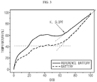
- a reference temperature profile as shown in FIG. 3 may be plotted.
- the reference temperature data stored in the memory unit 110 in advance may have a matrix structure of data pairs about the temperature according to DOD, or the reference temperature increase rate K1 of the discharge last half with DOD of 50% or above calculated therefrom.
- the reference temperature increase rate K1 may be calculated directly from the reference temperature data or may be obtained from a graph tangent slope of the DOD last half from the temperature profile as shown in FIG. 3 (corresponding to Step s2 in FIG. 2 as the second step of the SOH analyzing method).
- the graph tangent slope of the DOD last half may be obtained after finding an onset second inflection point in the reference temperature profile.
- the reference temperature increase rate K1 of the discharge last half with DOD of 50% or above is determined as a comparison standard, judging that the temperature increase rate of the DOD last half represents the internal state of the battery better compared to the temperature increase rate of the DOD first half.
- the battery may be affected by the ambient temperature during the measurement, it is preferable to measure the surface temperature of the reference battery in various temperature environments through experiments and store as data in advance. For example, the surface temperature change of the reference battery at various temperatures such as -5°C, 10°C and 25°C are measured in advance.
- control unit 120 may be electrically coupled to a voltage measuring unit 130, a current measuring unit 140 and a temperature measuring unit 150 to determine other variables such as SOC and resistance of the battery B.
- the voltage measuring unit 130 includes a known voltage measurement circuit, and periodically measures the voltage of the battery B at a time interval under the control of the control unit 120, and outputs the measured voltage to the control unit 120. Then, the control unit 120 stores the periodically inputted measured voltage in the memory unit 110. If the voltage of the battery B is measured, the depth of discharge may be known therefrom.
- the current measuring unit 140 includes a sense resistor or a hall sensor, and measures the magnitude of the charge or discharge current of the battery B at a time interval under the control of the control unit 120 and outputs the measured current to the control unit 120. Then, the control unit 120 stores the periodically inputted measured current in the memory unit 110.
- the temperature measuring unit 150 includes a thermocouple that is a type of temperature sensor, and periodically measures the temperature of the battery B at a time interval under the control of the control unit 120 and outputs the measured temperature to the control unit 120. Then, the control unit 120 stores the periodically inputted measured temperature in the memory unit 110.
- a measuring and recording unit 122 of the control unit 120 measures temperature data according to DOD while the battery B in a full charge state is being discharged and stores the measured temperature data in the memory unit 110 (corresponding to Step s3 of FIG. 2 as the third step of the SOH analyzing method).
- the temperature of the battery B measured by the temperature measuring unit 150 is stored in the memory unit 110 as the temperature data according to DOD by the measuring and recording unit 122.
- the discharge is a constant current (CC) discharge and the temperature is obtained by measuring the surface temperature of the battery B, identical to the reference battery.
- CC constant current
- a calculating unit 124 of the control unit 120 calculates a temperature increase rate K2 of the discharge last half with DOD of 50% or above from the temperature data according to DOD obtained by the measuring and recording unit 122.
- the temperature increase rate K2 may also be calculated directly from the temperature data or may also be obtained from the graph tangent slope of the DOD last half from the temperature profile as shown in FIG. 3 (corresponding to Step s4 of FIG. 2 as the fourth step of the SOH analysis method).
- the graph tangent slope of the DOD last half may be obtained after finding the onset second inflection point in the temperature profile, as described above in relation to the reference temperature profile.
- a determining unit 126 of the control unit 120 determines the degree of degradation of the battery B in comparison to the reference battery by comparing the reference temperature increase rate K1 and the temperature increase rate K2 (corresponding to Step s5 of FIG. 2 as the fifth step of the SOH analyzing method).
- the ambient temperature at measurement may be considered together so that, if the temperature of the battery B in the actual measurement environment is 25°C, the measurement result can be compared with the temperature data of the reference battery measured at 25°C in advance.
- the use cycle of the battery progresses, intercalation and deintercalation of lithium ions are repeated at a negative electrode and a positive electrode to cause phase transition and degrade the structural change.
- the inventor of the present disclosure has found through research that the degree of degradation caused by the structural change has a significant effect on the amount of entropic heat generated within the battery. It has been experimentally found that a battery with a lot of use cycles has different entropic heat compared with the initial battery, namely the reference battery. Thus, the present disclosure has been proposed based on the fact that the degree of degradation of the battery can be deduced by comparatively analyzing temperature changes.
- the voltage of the battery is measured during a constant current discharge (from which DOD can be found), and the temperature change of the battery surface is measured so that the degree of degradation of the battery is figured out by comparing the temperature increase rate.
- K ⁇ surface temperature / ⁇ DOD
- an absolute value of K at the battery B subject to measurement is greater than an absolute value of K of the reference battery, namely if
- the battery may be determined as having a greater degree of degradation.
- the determining unit 126 may quantitatively obtain the degree of degradation of the battery B. If the correlation data between the degree of degradation and the temperature increase rate are accumulated by performing the third step (s3) to the fifth step (s5) of the SOH analyzing method for several sample batteries, it is possible to determine SOH (%) at any temperature increase rate by synthesizing all data.
- SOC may be classified into various sections such that the battery has SOH of 100% if the measured temperature increase rate of the battery is equal to the reference temperature increase rate, the battery has SOH of 90% if the temperature increase rate increases within 10% of the reference temperature increase rate, the battery has SOH of 80% if the temperature increase rate increases within 20% of the reference temperature increase rate, and the like. This may vary depending on battery types and should be determined experimentally. If the SOH value corresponding to each temperature increase rate is determined in advance, for example stored in a lookup table, after the actual temperature increase rate K2 the battery B is be calculated the SOH value corresponding thereto may be found and quantitatively displayed instantly.
- the SOH of the battery B analyzed as described above may be used as an important indicator for determining whether the battery B is reusable as described later, and may also be used for output estimation while the battery B is in use.
- the control unit 120 may also determine the output of the battery B by utilizing the analyzed SOH of the battery B and store the determined output information in the memory unit 110.
- control unit 120 may be combined with a communication interface (I/F) 160 to output at least one of the estimated output and SOH values to an external device (not shown) through the communication interface 160.
- I/F communication interface
- the external device may be a controller of a device load that is supplied with electrical energy from the battery B, but the present disclosure is not limited thereto.
- the related system may be configured so that the battery B is fully charged and then discharged when the battery charge/discharge is terminated, for example when a vehicle starter key is turned off, in order to perform SOH analyzing method. Also, since the battery B is in a full discharge state after the SOH analysis step, the system may be configured so that the battery B is charged for use.
- the SOH analysis step may not be separately implemented while the battery is not in use, but the system may be configured such that the SOH analyzing method as above is used while the battery is in use.
- control unit 120 may selectively include a processor, an Application-Specific Integrated Circuit (ASIC), a chipset, a logic circuit, a register, a communication modem and a data processing device known in the art to execute various control logics disclosed herein.
- ASIC Application-Specific Integrated Circuit
- control unit 120 may be implemented as a set of program modules.
- the program module may be stored in the memory unit 110, and executed by the processor.
- the memory unit 110 may be inside or outside of the processor, and may be connected to the processor with a variety of well-known means.
- At least one of the control logics associated with the first step (s1) to the fifth step (s2) of the SOH analyzing method as described above may be combined, and the combined control logics may be written in computer-readable coding systems and stored in computer-readable recording media.
- the recording media is not limited to a particular type and includes any type that can be accessed by the processor included in the computer.
- the recording media may include at least one selected from the group consisting of ROM, RAM, register, CD-ROM, magnetic tape, hard disk, floppy disk and an optical data recording device.
- the coding systems may be modulated to a carrier signal and included in a communication carrier at a specific point in time, and may be stored and executed in computers connected via a network in distributed manner. Additionally, functional programs, codes and segments for implementing the combined control logics may be easily inferred by programs in the technical field pertaining to the present disclosure.
- the SOH analyzing according to the present disclosure may be included as part of a system called a BMS. Additionally, the BMS may be mounted in various types of electric devices that can operate by electrical energy supplied from the battery B.
- the electric device may be a mobile phone, a mobile computer device such as a laptop computer and a tablet computer, or a handheld multimedia device including a digital camera, a video camera and an audio/video player.
- the electric device may be an electrically powered device that can move by electricity such as an electric vehicle, a hybrid electric vehicle, an electric bike, an electric motorcycle, an electric locomotive, an electric ship and an electric aircraft, or a power tool including a motor such as an electric drill and an electric grinder.
- electricity such as an electric vehicle, a hybrid electric vehicle, an electric bike, an electric motorcycle, an electric locomotive, an electric ship and an electric aircraft, or a power tool including a motor such as an electric drill and an electric grinder.
- the electric device may be a large-capacity energy storage system installed in a power grid to store renewable energy or redundant power, or an uninterruptible power system to supply power to various types of information communication devices including a server computer or a mobile communication device in an emergent situation such as blackout.
- FIG. 4 is a diagram schematically showing a battery reuse diagnosing apparatus according to an embodiment of the present disclosure.
- the battery reuse diagnosing apparatus 300 includes the SOH analyzing apparatus 100 of the present disclosure, a battery holder 200, a display device 220 and the like.
- EV and HEV have been put to practical use by recent research and development. If batteries for such vehicles are used widely, a large number of used batteries will be generated as the vehicles are scrapped and the batteries are exchanged.
- the used batteries may include broken, defective or dead batteries but may also include batteries that are still available.
- a battery for a vehicle may be reused as a battery for ESS that may be used in milder conditions. Thus, it is economically and environmentally attractive to dispose of broken or seriously degraded batteries among the used batteries, and separately classify batteries that are still available to be reused in other purposes.
- the battery reuse diagnosing apparatus 300 of the present disclosure may be used to properly classify the used batteries.
- a battery B subjected to reuse diagnosis is placed in the battery holder 200 and connected to the SOH analyzing apparatus 100 through a circuit 210. While the battery B is being discharged at a constant current, the voltage of the battery B is measured and sent to the memory unit of the SOH analyzing apparatus 100, and the surface temperature of the battery B is measured by the temperature measuring unit 150 and transmitted to the measuring and recording unit of the SOH analyzing apparatus 100, thereby obtaining temperature data of the battery B.
- the SOH analyzing apparatus 100 determines the degree of degradation of the battery B by comparing the reference temperature increase rate and the temperature increase rate of the battery B as described above.
- the calculation result and the determination result of the SOH analyzing apparatus 100 performed at this time may be displayed through the display device 220.
- the temperature profile described above with reference to FIG. 3 or the SOH value of the battery B read out from the stored SOH value for each temperature increase rate may be displayed so that the user may easily check the SOH value and the like. The user may see the result on the display device 220 and determine whether to discard or reuse the battery B.
- the battery reuse diagnosing method according to the present disclosure may be accomplished by using the battery reuse diagnosing apparatus as described above, or by using the SOH analyzing method as described above.
- the surface temperature of the reference battery according to DOD is measured while the reference battery in the full charge state is being discharged at a constant current, thereby obtaining the reference temperature profile according to DOD. This corresponds to Step s1 of FIG. 2 .
- the slope S1 is calculated in the reference temperature profile. This corresponds to Step s2 of FIG. 2 .
- Step s3 of FIG. 2 corresponds to the use of the battery reuse diagnosing apparatus of FIG. 4 .
- the slope S2' is calculated in the temperature profile of the battery subject to reuse diagnosis according to DOD. This corresponds to Step s4 of FIG. 2 and also corresponds to the use of the battery reuse diagnosing apparatus of FIG. 4 .
- Step s5 of FIG. 2 corresponds to the use of the battery reuse diagnosing apparatus of FIG. 4 .
- the surface temperature of each sample battery according to DOD may be obtained while each sample battery in a full charge state is being at a constant current, thereby acquiring the temperature profile of each sample battery according to DOD.
- the slope S2 may be calculated from the temperature profile of each sample battery according to DOD, and then the correlation data between the degree of degradation and the slope S2 may be accumulated and recorded.
- the degree of degradation corresponding to the slope S2' of the battery subject to diagnosis may be found and used to diagnose the degree of degradation of the battery subjected to reuse diagnosis.
- the battery subjected to reuse diagnosis is analyzed to have SOH of 75%, the battery will be classified as a reusable battery and then follow-up measures are conducted to the battery for the next use.
- the battery subjected to reuse diagnosis is analyzed to have SOH of 60%, the battery is classified as a wasted battery and follow-up measures are conducted to the battery.
- the battery reuse diagnosis method according to the present disclosure is utilized in this way.
- components designated by ' ⁇ unit' should be understood as elements which are classified functionally rather than physically. Accordingly, each component may be selectively combined with other component, or may be divided into subcomponents for efficient execution of control logic(s). However, it is obvious to those skilled in the art that even though the components are combined or divided, if the sameness of functions can be acknowledged, the combined or divided components should be construed as being in the scope of the present disclosure.
Landscapes
- Physics & Mathematics (AREA)
- General Physics & Mathematics (AREA)
- Secondary Cells (AREA)
Applications Claiming Priority (2)
| Application Number | Priority Date | Filing Date | Title |
|---|---|---|---|
| KR1020180009875A KR102255485B1 (ko) | 2018-01-26 | 2018-01-26 | Soh 분석 장치 및 방법 |
| PCT/KR2019/000170 WO2019146928A1 (ko) | 2018-01-26 | 2019-01-04 | Soh 분석 장치 및 방법 |
Publications (3)
| Publication Number | Publication Date |
|---|---|
| EP3671244A1 true EP3671244A1 (de) | 2020-06-24 |
| EP3671244A4 EP3671244A4 (de) | 2020-12-16 |
| EP3671244B1 EP3671244B1 (de) | 2023-05-17 |
Family
ID=67395488
Family Applications (1)
| Application Number | Title | Priority Date | Filing Date |
|---|---|---|---|
| EP19744525.7A Active EP3671244B1 (de) | 2018-01-26 | 2019-01-04 | Vorrichtung und verfahren zur analyse des alterungszustandes einer batterie |
Country Status (8)
| Country | Link |
|---|---|
| US (1) | US11187757B2 (de) |
| EP (1) | EP3671244B1 (de) |
| KR (1) | KR102255485B1 (de) |
| CN (1) | CN110799849B (de) |
| ES (1) | ES2956379T3 (de) |
| HU (1) | HUE062070T2 (de) |
| PL (1) | PL3671244T3 (de) |
| WO (1) | WO2019146928A1 (de) |
Cited By (4)
| Publication number | Priority date | Publication date | Assignee | Title |
|---|---|---|---|---|
| EP4206712A4 (de) * | 2020-10-30 | 2024-03-13 | LG Energy Solution, Ltd. | Vorrichtung und verfahren zur batteriediagnose |
| EP4382931A1 (de) * | 2022-12-07 | 2024-06-12 | Volvo Truck Corporation | Vorhersage der alterung von elektrischen energiespeichern |
| MA58892A1 (fr) * | 2022-12-13 | 2024-06-28 | BOUDOUDOUH Soukaina | Système et procédé de gestion de la durée de vie dans un élément de stockage |
| US12444962B2 (en) | 2020-10-06 | 2025-10-14 | Samsung Electronics Co., Ltd. | Methods and systems for detecting faulty behavior in a battery |
Families Citing this family (10)
| Publication number | Priority date | Publication date | Assignee | Title |
|---|---|---|---|---|
| KR102687127B1 (ko) * | 2019-05-15 | 2024-07-23 | 에스케이온 주식회사 | Bms 장치 및 그 제어 방법 |
| KR102871577B1 (ko) * | 2019-09-04 | 2025-10-17 | 삼성전자주식회사 | 배터리 충전 장치 및 방법 |
| KR102180118B1 (ko) * | 2020-01-03 | 2020-11-18 | 김용현 | 차량의 배터리 성능 평가 방법 및 장치 |
| CN111090051B (zh) * | 2020-01-21 | 2020-11-10 | 北京空间飞行器总体设计部 | 一种卫星用镉镍蓄电池放电终压自主诊断方法 |
| KR102876421B1 (ko) * | 2020-10-08 | 2025-10-23 | 주식회사 엘지에너지솔루션 | 배터리 관리 장치 및 방법 |
| CN113567863B (zh) * | 2021-06-11 | 2022-04-01 | 北京航空航天大学 | 基于量子同化与数据填充的异常退化锂电池容量预测方法 |
| KR102897582B1 (ko) * | 2022-09-13 | 2025-12-09 | 삼성전자주식회사 | 배터리 모델 최적화 방법 및 이를 수행하는 전자 장치 |
| KR102916063B1 (ko) * | 2022-11-22 | 2026-01-20 | 주식회사 엘지에너지솔루션 | 배터리 soh 추정 장치 및 방법 |
| WO2026054345A1 (ko) * | 2024-09-09 | 2026-03-12 | 주식회사 엘지에너지솔루션 | 배터리 진단 장치 및 배터리 진단 방법 |
| CN121232062B (zh) * | 2025-12-02 | 2026-03-06 | 深圳市德兰明海新能源股份有限公司 | 一种电池健康状态值估算方法 |
Family Cites Families (27)
| Publication number | Priority date | Publication date | Assignee | Title |
|---|---|---|---|---|
| JPH10341505A (ja) * | 1997-06-06 | 1998-12-22 | Nissan Motor Co Ltd | 電気自動車の制御装置 |
| TW535308B (en) | 2000-05-23 | 2003-06-01 | Canon Kk | Detecting method for detecting internal state of a rechargeable battery, detecting device for practicing said detecting method, and instrument provided with said |
| EP1689009A1 (de) | 2005-02-04 | 2006-08-09 | Yao, Li-ho | Batteriestapel |
| DE102005037717B3 (de) * | 2005-08-10 | 2006-12-21 | Daimlerchrysler Ag | Verfahren und Vorrichtung zur Diagnose eines Außentemperatursensors |
| EP1933158B1 (de) | 2005-09-16 | 2018-04-25 | The Furukawa Electric Co., Ltd. | Verfahren und einrichtung zur beurteilung einer sekundärzellenverschlechterung und stromversorgungssystem |
| US8036839B2 (en) * | 2006-03-10 | 2011-10-11 | Shin-Kobe Electric Machinery Co., Ltd. | Battery state determining apparatus |
| JP2008039526A (ja) | 2006-08-03 | 2008-02-21 | Auto Network Gijutsu Kenkyusho:Kk | 電池劣化診断方法、電池劣化診断装置及びコンピュータプログラム |
| WO2009118910A1 (ja) | 2008-03-28 | 2009-10-01 | 新神戸電機株式会社 | 電池状態判定方法および自動車 |
| JP5515524B2 (ja) | 2009-09-01 | 2014-06-11 | 日産自動車株式会社 | 二次電池の劣化状態判別システム、および二次電池の劣化状態判別方法 |
| US8648603B2 (en) | 2010-04-21 | 2014-02-11 | Toyota Jidosha Kabushiki Kaisha | Deterioration degree calculating apparatus for secondary battery, vehicle equipped with the apparatus, and deterioration degree calculating method for secondary battery |
| US9201121B2 (en) * | 2010-12-06 | 2015-12-01 | Texas Instruments Incorporated | System and method for sensing battery capacity |
| CN103402809B (zh) | 2011-01-13 | 2016-11-09 | 卡明斯公司 | 用于控制混合动力传动系中的功率输出分布的系统、方法和装置 |
| US9177466B2 (en) | 2011-01-20 | 2015-11-03 | Indiana University Research And Technology Corporation | Advanced battery early warning and monitoring system |
| JP5852399B2 (ja) | 2011-10-17 | 2016-02-03 | インターナショナル・ビジネス・マシーンズ・コーポレーションInternational Business Machines Corporation | バッテリの状態予測システム、方法及びプログラム |
| CN104471415B (zh) | 2012-04-27 | 2017-09-01 | 加州理工学院 | 用于电池应用的嵌入式芯片 |
| EP2837944B1 (de) | 2012-04-30 | 2019-05-01 | LG Chem, Ltd. | Verfahren und vorrichtung zum schätzen von parametern einer sekundärbatterie |
| JP6040684B2 (ja) * | 2012-09-28 | 2016-12-07 | 富士通株式会社 | 二次電池の状態評価装置、二次電池の状態評価方法、及び、二次電池の状態評価プログラム |
| CN103969585B (zh) | 2013-01-31 | 2018-03-30 | 国际商业机器公司 | 评估电池的使用状况的方法和装置、相关系统和车辆 |
| US10732228B2 (en) | 2013-01-31 | 2020-08-04 | Utopus Insights, Inc. | Estimating condition of battery, related system and vehicle |
| WO2014167644A1 (ja) | 2013-04-09 | 2014-10-16 | 三菱電機株式会社 | 電圧センサの故障検出装置 |
| US9457682B2 (en) | 2013-08-30 | 2016-10-04 | GM Global Technology Operations LLC | Method for predicting charging process duration |
| JP6165620B2 (ja) | 2013-12-19 | 2017-07-19 | 日立オートモティブシステムズ株式会社 | 二次電池モジュールおよび二次電池監視装置 |
| KR20160011449A (ko) | 2014-07-22 | 2016-02-01 | 현대모비스 주식회사 | 전해질의 밀도변화를 이용한 배터리의 노화상태 산출 장치 및 방법 |
| JP2016081638A (ja) | 2014-10-14 | 2016-05-16 | トヨタ自動車株式会社 | 電池システム |
| KR101903225B1 (ko) | 2015-08-21 | 2018-11-13 | 주식회사 엘지화학 | 이차 전지의 퇴화도 추정 장치 및 방법 |
| KR102470882B1 (ko) | 2016-03-31 | 2022-11-25 | 에스케이온 주식회사 | 단위배터리 모듈 및 배터리 셀의 열화도 산출방법 |
| KR20180009875A (ko) | 2016-07-20 | 2018-01-30 | 현대중공업 주식회사 | 지게차의 마스트 기울기 제어 장치 및 방법 |
-
2018
- 2018-01-26 KR KR1020180009875A patent/KR102255485B1/ko active Active
-
2019
- 2019-01-04 WO PCT/KR2019/000170 patent/WO2019146928A1/ko not_active Ceased
- 2019-01-04 PL PL19744525.7T patent/PL3671244T3/pl unknown
- 2019-01-04 CN CN201980002904.9A patent/CN110799849B/zh active Active
- 2019-01-04 EP EP19744525.7A patent/EP3671244B1/de active Active
- 2019-01-04 HU HUE19744525A patent/HUE062070T2/hu unknown
- 2019-01-04 US US16/625,361 patent/US11187757B2/en active Active
- 2019-01-04 ES ES19744525T patent/ES2956379T3/es active Active
Cited By (5)
| Publication number | Priority date | Publication date | Assignee | Title |
|---|---|---|---|---|
| US12444962B2 (en) | 2020-10-06 | 2025-10-14 | Samsung Electronics Co., Ltd. | Methods and systems for detecting faulty behavior in a battery |
| EP4206712A4 (de) * | 2020-10-30 | 2024-03-13 | LG Energy Solution, Ltd. | Vorrichtung und verfahren zur batteriediagnose |
| EP4382931A1 (de) * | 2022-12-07 | 2024-06-12 | Volvo Truck Corporation | Vorhersage der alterung von elektrischen energiespeichern |
| MA58892A1 (fr) * | 2022-12-13 | 2024-06-28 | BOUDOUDOUH Soukaina | Système et procédé de gestion de la durée de vie dans un élément de stockage |
| MA58892B1 (fr) * | 2022-12-13 | 2024-11-29 | BOUDOUDOUH Soukaina | Système et procédé de gestion de la durée de vie dans un élément de stockage |
Also Published As
| Publication number | Publication date |
|---|---|
| CN110799849A (zh) | 2020-02-14 |
| US11187757B2 (en) | 2021-11-30 |
| EP3671244B1 (de) | 2023-05-17 |
| KR102255485B1 (ko) | 2021-05-24 |
| KR20190090993A (ko) | 2019-08-05 |
| HUE062070T2 (hu) | 2023-09-28 |
| WO2019146928A1 (ko) | 2019-08-01 |
| US20210148985A1 (en) | 2021-05-20 |
| PL3671244T3 (pl) | 2023-07-24 |
| ES2956379T3 (es) | 2023-12-20 |
| EP3671244A4 (de) | 2020-12-16 |
| CN110799849B (zh) | 2022-03-22 |
Similar Documents
| Publication | Publication Date | Title |
|---|---|---|
| EP3671244B1 (de) | Vorrichtung und verfahren zur analyse des alterungszustandes einer batterie | |
| US11105861B2 (en) | Device and method for estimating battery resistance | |
| CN110869784B (zh) | 用于估计soc-ocv曲线的方法和设备 | |
| US10739407B2 (en) | System and method for estimating state of health using battery model parameter | |
| CN114158276B (zh) | 检测镀锂的方法和通过使用其来管理电池的方法和装置 | |
| KR102738216B1 (ko) | 배터리 진단 장치 및 방법 | |
| KR101547005B1 (ko) | 배터리 잔존 용량 추정 장치 및 방법 | |
| US9535132B2 (en) | Systems and methods for determining battery system performance degradation | |
| KR101783918B1 (ko) | 이차 전지의 저항 추정 장치 및 방법 | |
| EP4376161A1 (de) | Vorrichtung und verfahren zur verwaltung einer batterie | |
| US12253572B2 (en) | Battery diagnosing apparatus and method | |
| KR101498764B1 (ko) | 배터리의 저항측정방법 및 장치, 이를 이용한 배터리 관리 시스템 | |
| CN105313715A (zh) | 用于在电量维持使用期间估计电池组容量的系统和方法 | |
| US20250244404A1 (en) | Apparatus and method for diagnosing battery | |
| KR20260056592A (ko) | 배터리 진단 장치 및 방법 | |
| KR20260058691A (ko) | 배터리 진단 장치 및 방법 | |
| WO2026069783A1 (ja) | 電池制御装置及び車両制御装置 | |
| Singha et al. | Impact of Kalman Filtering in Battery Management Systems |
Legal Events
| Date | Code | Title | Description |
|---|---|---|---|
| STAA | Information on the status of an ep patent application or granted ep patent |
Free format text: STATUS: THE INTERNATIONAL PUBLICATION HAS BEEN MADE |
|
| PUAI | Public reference made under article 153(3) epc to a published international application that has entered the european phase |
Free format text: ORIGINAL CODE: 0009012 |
|
| STAA | Information on the status of an ep patent application or granted ep patent |
Free format text: STATUS: REQUEST FOR EXAMINATION WAS MADE |
|
| 17P | Request for examination filed |
Effective date: 20200316 |
|
| AK | Designated contracting states |
Kind code of ref document: A1 Designated state(s): AL AT BE BG CH CY CZ DE DK EE ES FI FR GB GR HR HU IE IS IT LI LT LU LV MC MK MT NL NO PL PT RO RS SE SI SK SM TR |
|
| AX | Request for extension of the european patent |
Extension state: BA ME |
|
| A4 | Supplementary search report drawn up and despatched |
Effective date: 20201118 |
|
| RIC1 | Information provided on ipc code assigned before grant |
Ipc: G01R 31/36 20200101ALI20201112BHEP Ipc: G01R 31/392 20190101AFI20201112BHEP Ipc: G01R 31/382 20190101ALI20201112BHEP |
|
| DAV | Request for validation of the european patent (deleted) | ||
| DAX | Request for extension of the european patent (deleted) | ||
| RAP1 | Party data changed (applicant data changed or rights of an application transferred) |
Owner name: LG ENERGY SOLUTION LTD. |
|
| RAP3 | Party data changed (applicant data changed or rights of an application transferred) |
Owner name: LG ENERGY SOLUTION, LTD. |
|
| GRAP | Despatch of communication of intention to grant a patent |
Free format text: ORIGINAL CODE: EPIDOSNIGR1 |
|
| STAA | Information on the status of an ep patent application or granted ep patent |
Free format text: STATUS: GRANT OF PATENT IS INTENDED |
|
| RIC1 | Information provided on ipc code assigned before grant |
Ipc: G01R 31/374 20190101ALI20221118BHEP Ipc: G01R 31/382 20190101ALI20221118BHEP Ipc: G01R 31/36 20200101ALI20221118BHEP Ipc: G01R 31/392 20190101AFI20221118BHEP |
|
| INTG | Intention to grant announced |
Effective date: 20221215 |
|
| GRAS | Grant fee paid |
Free format text: ORIGINAL CODE: EPIDOSNIGR3 |
|
| GRAA | (expected) grant |
Free format text: ORIGINAL CODE: 0009210 |
|
| STAA | Information on the status of an ep patent application or granted ep patent |
Free format text: STATUS: THE PATENT HAS BEEN GRANTED |
|
| AK | Designated contracting states |
Kind code of ref document: B1 Designated state(s): AL AT BE BG CH CY CZ DE DK EE ES FI FR GB GR HR HU IE IS IT LI LT LU LV MC MK MT NL NO PL PT RO RS SE SI SK SM TR |
|
| REG | Reference to a national code |
Ref country code: GB Ref legal event code: FG4D |
|
| REG | Reference to a national code |
Ref country code: CH Ref legal event code: EP |
|
| REG | Reference to a national code |
Ref country code: DE Ref legal event code: R096 Ref document number: 602019029081 Country of ref document: DE |
|
| REG | Reference to a national code |
Ref country code: IE Ref legal event code: FG4D |
|
| REG | Reference to a national code |
Ref country code: AT Ref legal event code: REF Ref document number: 1568601 Country of ref document: AT Kind code of ref document: T Effective date: 20230615 |
|
| P01 | Opt-out of the competence of the unified patent court (upc) registered |
Effective date: 20230525 |
|
| REG | Reference to a national code |
Ref country code: NL Ref legal event code: FP |
|
| REG | Reference to a national code |
Ref country code: SE Ref legal event code: TRGR |
|
| REG | Reference to a national code |
Ref country code: LT Ref legal event code: MG9D |
|
| REG | Reference to a national code |
Ref country code: HU Ref legal event code: AG4A Ref document number: E062070 Country of ref document: HU |
|
| REG | Reference to a national code |
Ref country code: AT Ref legal event code: MK05 Ref document number: 1568601 Country of ref document: AT Kind code of ref document: T Effective date: 20230517 |
|
| PG25 | Lapsed in a contracting state [announced via postgrant information from national office to epo] |
Ref country code: PT Free format text: LAPSE BECAUSE OF FAILURE TO SUBMIT A TRANSLATION OF THE DESCRIPTION OR TO PAY THE FEE WITHIN THE PRESCRIBED TIME-LIMIT Effective date: 20230918 Ref country code: NO Free format text: LAPSE BECAUSE OF FAILURE TO SUBMIT A TRANSLATION OF THE DESCRIPTION OR TO PAY THE FEE WITHIN THE PRESCRIBED TIME-LIMIT Effective date: 20230817 Ref country code: AT Free format text: LAPSE BECAUSE OF FAILURE TO SUBMIT A TRANSLATION OF THE DESCRIPTION OR TO PAY THE FEE WITHIN THE PRESCRIBED TIME-LIMIT Effective date: 20230517 |
|
| PG25 | Lapsed in a contracting state [announced via postgrant information from national office to epo] |
Ref country code: RS Free format text: LAPSE BECAUSE OF FAILURE TO SUBMIT A TRANSLATION OF THE DESCRIPTION OR TO PAY THE FEE WITHIN THE PRESCRIBED TIME-LIMIT Effective date: 20230517 Ref country code: LV Free format text: LAPSE BECAUSE OF FAILURE TO SUBMIT A TRANSLATION OF THE DESCRIPTION OR TO PAY THE FEE WITHIN THE PRESCRIBED TIME-LIMIT Effective date: 20230517 Ref country code: LT Free format text: LAPSE BECAUSE OF FAILURE TO SUBMIT A TRANSLATION OF THE DESCRIPTION OR TO PAY THE FEE WITHIN THE PRESCRIBED TIME-LIMIT Effective date: 20230517 Ref country code: IS Free format text: LAPSE BECAUSE OF FAILURE TO SUBMIT A TRANSLATION OF THE DESCRIPTION OR TO PAY THE FEE WITHIN THE PRESCRIBED TIME-LIMIT Effective date: 20230917 Ref country code: HR Free format text: LAPSE BECAUSE OF FAILURE TO SUBMIT A TRANSLATION OF THE DESCRIPTION OR TO PAY THE FEE WITHIN THE PRESCRIBED TIME-LIMIT Effective date: 20230517 Ref country code: GR Free format text: LAPSE BECAUSE OF FAILURE TO SUBMIT A TRANSLATION OF THE DESCRIPTION OR TO PAY THE FEE WITHIN THE PRESCRIBED TIME-LIMIT Effective date: 20230818 |
|
| REG | Reference to a national code |
Ref country code: ES Ref legal event code: FG2A Ref document number: 2956379 Country of ref document: ES Kind code of ref document: T3 Effective date: 20231220 |
|
| PG25 | Lapsed in a contracting state [announced via postgrant information from national office to epo] |
Ref country code: FI Free format text: LAPSE BECAUSE OF FAILURE TO SUBMIT A TRANSLATION OF THE DESCRIPTION OR TO PAY THE FEE WITHIN THE PRESCRIBED TIME-LIMIT Effective date: 20230517 |
|
| PG25 | Lapsed in a contracting state [announced via postgrant information from national office to epo] |
Ref country code: SK Free format text: LAPSE BECAUSE OF FAILURE TO SUBMIT A TRANSLATION OF THE DESCRIPTION OR TO PAY THE FEE WITHIN THE PRESCRIBED TIME-LIMIT Effective date: 20230517 |
|
| PG25 | Lapsed in a contracting state [announced via postgrant information from national office to epo] |
Ref country code: SM Free format text: LAPSE BECAUSE OF FAILURE TO SUBMIT A TRANSLATION OF THE DESCRIPTION OR TO PAY THE FEE WITHIN THE PRESCRIBED TIME-LIMIT Effective date: 20230517 Ref country code: SK Free format text: LAPSE BECAUSE OF FAILURE TO SUBMIT A TRANSLATION OF THE DESCRIPTION OR TO PAY THE FEE WITHIN THE PRESCRIBED TIME-LIMIT Effective date: 20230517 Ref country code: RO Free format text: LAPSE BECAUSE OF FAILURE TO SUBMIT A TRANSLATION OF THE DESCRIPTION OR TO PAY THE FEE WITHIN THE PRESCRIBED TIME-LIMIT Effective date: 20230517 Ref country code: EE Free format text: LAPSE BECAUSE OF FAILURE TO SUBMIT A TRANSLATION OF THE DESCRIPTION OR TO PAY THE FEE WITHIN THE PRESCRIBED TIME-LIMIT Effective date: 20230517 Ref country code: DK Free format text: LAPSE BECAUSE OF FAILURE TO SUBMIT A TRANSLATION OF THE DESCRIPTION OR TO PAY THE FEE WITHIN THE PRESCRIBED TIME-LIMIT Effective date: 20230517 Ref country code: CZ Free format text: LAPSE BECAUSE OF FAILURE TO SUBMIT A TRANSLATION OF THE DESCRIPTION OR TO PAY THE FEE WITHIN THE PRESCRIBED TIME-LIMIT Effective date: 20230517 |
|
| REG | Reference to a national code |
Ref country code: DE Ref legal event code: R097 Ref document number: 602019029081 Country of ref document: DE |
|
| PLBE | No opposition filed within time limit |
Free format text: ORIGINAL CODE: 0009261 |
|
| STAA | Information on the status of an ep patent application or granted ep patent |
Free format text: STATUS: NO OPPOSITION FILED WITHIN TIME LIMIT |
|
| 26N | No opposition filed |
Effective date: 20240220 |
|
| PG25 | Lapsed in a contracting state [announced via postgrant information from national office to epo] |
Ref country code: SI Free format text: LAPSE BECAUSE OF FAILURE TO SUBMIT A TRANSLATION OF THE DESCRIPTION OR TO PAY THE FEE WITHIN THE PRESCRIBED TIME-LIMIT Effective date: 20230517 |
|
| PG25 | Lapsed in a contracting state [announced via postgrant information from national office to epo] |
Ref country code: SI Free format text: LAPSE BECAUSE OF FAILURE TO SUBMIT A TRANSLATION OF THE DESCRIPTION OR TO PAY THE FEE WITHIN THE PRESCRIBED TIME-LIMIT Effective date: 20230517 |
|
| PG25 | Lapsed in a contracting state [announced via postgrant information from national office to epo] |
Ref country code: MC Free format text: LAPSE BECAUSE OF FAILURE TO SUBMIT A TRANSLATION OF THE DESCRIPTION OR TO PAY THE FEE WITHIN THE PRESCRIBED TIME-LIMIT Effective date: 20230517 |
|
| PG25 | Lapsed in a contracting state [announced via postgrant information from national office to epo] |
Ref country code: MC Free format text: LAPSE BECAUSE OF FAILURE TO SUBMIT A TRANSLATION OF THE DESCRIPTION OR TO PAY THE FEE WITHIN THE PRESCRIBED TIME-LIMIT Effective date: 20230517 |
|
| REG | Reference to a national code |
Ref country code: CH Ref legal event code: PL |
|
| PG25 | Lapsed in a contracting state [announced via postgrant information from national office to epo] |
Ref country code: LU Free format text: LAPSE BECAUSE OF NON-PAYMENT OF DUE FEES Effective date: 20240104 |
|
| PG25 | Lapsed in a contracting state [announced via postgrant information from national office to epo] |
Ref country code: LU Free format text: LAPSE BECAUSE OF NON-PAYMENT OF DUE FEES Effective date: 20240104 |
|
| PG25 | Lapsed in a contracting state [announced via postgrant information from national office to epo] |
Ref country code: BE Free format text: LAPSE BECAUSE OF NON-PAYMENT OF DUE FEES Effective date: 20240131 |
|
| PG25 | Lapsed in a contracting state [announced via postgrant information from national office to epo] |
Ref country code: CH Free format text: LAPSE BECAUSE OF NON-PAYMENT OF DUE FEES Effective date: 20240131 |
|
| PG25 | Lapsed in a contracting state [announced via postgrant information from national office to epo] |
Ref country code: CH Free format text: LAPSE BECAUSE OF NON-PAYMENT OF DUE FEES Effective date: 20240131 Ref country code: BE Free format text: LAPSE BECAUSE OF NON-PAYMENT OF DUE FEES Effective date: 20240131 |
|
| REG | Reference to a national code |
Ref country code: BE Ref legal event code: MM Effective date: 20240131 |
|
| PG25 | Lapsed in a contracting state [announced via postgrant information from national office to epo] |
Ref country code: BG Free format text: LAPSE BECAUSE OF FAILURE TO SUBMIT A TRANSLATION OF THE DESCRIPTION OR TO PAY THE FEE WITHIN THE PRESCRIBED TIME-LIMIT Effective date: 20230517 |
|
| PG25 | Lapsed in a contracting state [announced via postgrant information from national office to epo] |
Ref country code: BG Free format text: LAPSE BECAUSE OF FAILURE TO SUBMIT A TRANSLATION OF THE DESCRIPTION OR TO PAY THE FEE WITHIN THE PRESCRIBED TIME-LIMIT Effective date: 20230517 |
|
| PG25 | Lapsed in a contracting state [announced via postgrant information from national office to epo] |
Ref country code: IE Free format text: LAPSE BECAUSE OF NON-PAYMENT OF DUE FEES Effective date: 20240104 |
|
| PG25 | Lapsed in a contracting state [announced via postgrant information from national office to epo] |
Ref country code: IE Free format text: LAPSE BECAUSE OF NON-PAYMENT OF DUE FEES Effective date: 20240104 |
|
| PG25 | Lapsed in a contracting state [announced via postgrant information from national office to epo] |
Ref country code: CY Free format text: LAPSE BECAUSE OF FAILURE TO SUBMIT A TRANSLATION OF THE DESCRIPTION OR TO PAY THE FEE WITHIN THE PRESCRIBED TIME-LIMIT; INVALID AB INITIO Effective date: 20190104 |
|
| PGFP | Annual fee paid to national office [announced via postgrant information from national office to epo] |
Ref country code: GB Payment date: 20251222 Year of fee payment: 8 |
|
| PGFP | Annual fee paid to national office [announced via postgrant information from national office to epo] |
Ref country code: NL Payment date: 20251223 Year of fee payment: 8 Ref country code: FR Payment date: 20251223 Year of fee payment: 8 |
|
| PGFP | Annual fee paid to national office [announced via postgrant information from national office to epo] |
Ref country code: SE Payment date: 20251223 Year of fee payment: 8 |
|
| PGFP | Annual fee paid to national office [announced via postgrant information from national office to epo] |
Ref country code: PL Payment date: 20251223 Year of fee payment: 8 |
|
| PGFP | Annual fee paid to national office [announced via postgrant information from national office to epo] |
Ref country code: HU Payment date: 20260129 Year of fee payment: 8 |
|
| PGFP | Annual fee paid to national office [announced via postgrant information from national office to epo] |
Ref country code: ES Payment date: 20260212 Year of fee payment: 8 |
|
| PGFP | Annual fee paid to national office [announced via postgrant information from national office to epo] |
Ref country code: DE Payment date: 20251222 Year of fee payment: 8 |
|
| PGFP | Annual fee paid to national office [announced via postgrant information from national office to epo] |
Ref country code: IT Payment date: 20251223 Year of fee payment: 8 |
|
| PGFP | Annual fee paid to national office [announced via postgrant information from national office to epo] |
Ref country code: TR Payment date: 20260102 Year of fee payment: 8 |