EP3671246A1 - Vorrichtung und verfahren zur prüfung und kalibrierung eines bauteils - Google Patents
Vorrichtung und verfahren zur prüfung und kalibrierung eines bauteils Download PDFInfo
- Publication number
- EP3671246A1 EP3671246A1 EP19216375.6A EP19216375A EP3671246A1 EP 3671246 A1 EP3671246 A1 EP 3671246A1 EP 19216375 A EP19216375 A EP 19216375A EP 3671246 A1 EP3671246 A1 EP 3671246A1
- Authority
- EP
- European Patent Office
- Prior art keywords
- component
- sample holder
- temperature
- module
- magnetic field
- Prior art date
- Legal status (The legal status is an assumption and is not a legal conclusion. Google has not performed a legal analysis and makes no representation as to the accuracy of the status listed.)
- Granted
Links
Images





Classifications
-
- G—PHYSICS
- G01—MEASURING; TESTING
- G01R—MEASURING ELECTRIC VARIABLES; MEASURING MAGNETIC VARIABLES
- G01R33/00—Arrangements or instruments for measuring magnetic variables
- G01R33/0017—Means for compensating offset magnetic fields or the magnetic flux to be measured; Means for generating calibration magnetic fields
-
- G—PHYSICS
- G01—MEASURING; TESTING
- G01R—MEASURING ELECTRIC VARIABLES; MEASURING MAGNETIC VARIABLES
- G01R33/00—Arrangements or instruments for measuring magnetic variables
- G01R33/0023—Electronic aspects, e.g. circuits for stimulation, evaluation, control; Treating the measured signals; calibration
- G01R33/0035—Calibration of single magnetic sensors, e.g. integrated calibration
-
- G—PHYSICS
- G01—MEASURING; TESTING
- G01R—MEASURING ELECTRIC VARIABLES; MEASURING MAGNETIC VARIABLES
- G01R35/00—Testing or calibrating of apparatus covered by the other groups of this subclass
-
- G—PHYSICS
- G01—MEASURING; TESTING
- G01R—MEASURING ELECTRIC VARIABLES; MEASURING MAGNETIC VARIABLES
- G01R33/00—Arrangements or instruments for measuring magnetic variables
- G01R33/007—Environmental aspects, e.g. temperature variations, radiation, stray fields
-
- G—PHYSICS
- G01—MEASURING; TESTING
- G01R—MEASURING ELECTRIC VARIABLES; MEASURING MAGNETIC VARIABLES
- G01R33/00—Arrangements or instruments for measuring magnetic variables
- G01R33/007—Environmental aspects, e.g. temperature variations, radiation, stray fields
- G01R33/0082—Compensation, e.g. compensating for temperature changes
-
- G—PHYSICS
- G01—MEASURING; TESTING
- G01R—MEASURING ELECTRIC VARIABLES; MEASURING MAGNETIC VARIABLES
- G01R33/00—Arrangements or instruments for measuring magnetic variables
- G01R33/20—Arrangements or instruments for measuring magnetic variables involving magnetic resonance
- G01R33/28—Details of apparatus provided for in groups G01R33/44 - G01R33/64
- G01R33/30—Sample handling arrangements, e.g. sample cells, spinning mechanisms
- G01R33/31—Temperature control thereof
-
- G—PHYSICS
- G01—MEASURING; TESTING
- G01R—MEASURING ELECTRIC VARIABLES; MEASURING MAGNETIC VARIABLES
- G01R35/00—Testing or calibrating of apparatus covered by the other groups of this subclass
- G01R35/005—Calibrating; Standards or reference devices, e.g. voltage or resistance standards, "golden" references
Definitions
- the invention relates to a device for testing and calibrating a component in a magnetic field and a method for carrying out the testing and calibration of the component in the magnetic field.
- the components To characterize and calibrate components such as magnetic field sensors, the components must be measured electrically under defined environmental parameters. These environmental parameters are e.g. the strength and orientation of the magnetic field as well as temperature and humidity. Some challenges have to be overcome. The environmental parameters must be checked very precisely independently of one another in order to obtain reliable measurement results. Reliable electrical contacting of the component with a measuring device must be ensured in the entire environmental parameter space. Parasitic interference, which can affect the function of the components (magnetic field sensors), for example mechanical stresses and / or magnetic interference fields, should be eliminated. The test environment must be robust and have a possible high throughput for use in a production hall.
- the invention is therefore based on the object of developing an improved device and an improved method for testing and calibrating a component.
- the device comprises a sample holder with a module for receiving at least one component, at least one magnetic field generator for generating a magnetic field around the sample holder, and a feed for feeding a temperature-controlled medium into the module and a discharge for removing a temperature-controlled one Medium from the module.
- the magnetic field generator is outside the area in which the environmental parameters are changed. This separation of the sources of the environmental parameters from one another and from the module enables the environmental parameters for the component to be changed more quickly, since the magnetic field generator also does not have to be heated, as is known in the prior art. Only the temperature of the smaller module with the component has to be changed. The ambient temperature of the magnetic field generator thus remains largely constant and therefore the magnetic field is also stable.
- the relatively small module with the component (s) can also be quickly heated and cooled.
- the sample holder has at least one insertion opening for the continuation of the temperature-controlled medium from the feed into a cavity in the module and at least one discharge opening of the temperature-controlled medium from the cavity of the module for the discharge.
- the component or the components are arranged between the insertion opening and the discharge opening in the cavity, so that the tempered medium flows against them.
- the sample holder with the module consists of two parts.
- the cavity is formed by opposite recesses in the two parts or in one of the two parts. By bringing the two parts together, the component is positioned in the cavity and can be reliably held and electrically contacted.
- the magnetic field generator comprises a plurality of coils which are arranged orthogonally to one another.
- the coils are constructed as Helmholtz coils and the magnetic field generated is thus largely homogeneous along the axis of the Helmholtz coils.
- the component is arranged in a largely homogeneous area around the common axes of the coils.
- the sample holder has several connection elements in the cavity for contacting the component. These connection elements are preferably designed as spring contact pins and contact the component when the two parts of the sample holder are brought together.
- the sample holder can also have guide channels in the module and cavity, which guide the tempered medium around the component.
- a control and measuring device for controlling the device with the temperature-controlled medium and the magnetic field and for evaluating the measurement data is also present.
- the method for testing and calibrating the component includes the introduction of a sample holder with a component mounted in a module into a magnetic field. Then a feed is brought to a feed opening in the sample holder and a discharge to a discharge opening in the sample holder. The module is then flowed with a tempered medium from the feed to the discharge. As mentioned above, the tempered medium is only carried out by the relatively small module. The environmental parameters can thus be changed more quickly.
- Fig. 1 and 2nd show two perspective representations of a device 10 for testing and calibrating at least one component 30, which is received in a sample holder 20.
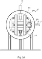
- the Figures 3A and 3B show a side view of the same device 10, wherein the Figure 3A the external appearance of the device 10 and Figure 3B a sectional view with the interior of the device 10 shows.
- Component 30 cannot be seen since component 30 is located within device 10.
- the sample holder 20 is in the Figures 4 , 5A , 5B , 6 and 7 shown in more detail and will be described in more detail later.
- Figs. 2nd and 3B show the sample holder 20 mounted in the device 10.
- the device 10 has a magnetic field generator, which in Fig. 1 and 2nd consists of a total of ten coils arranged in pairs. Only three pairs of coils 60a, 60b and 60c can be seen in the drawings. Two further pairs of coils are arranged within the magnetic field generator in the same orientation as the pair of coils 60c. Each coil pair is preferably in a kind of "Helmholtz" arrangement with a largely homogeneous magnetic field formed near its coil axis.
- the coil pairs 60a, 60b and 60c are each arranged orthogonally to one another and their axes have a common intersection point 15 (shown in the sectional view Figure 3B ) on.
- the component 30 is mounted in the device 10 such that it is largely located at or around the intersection 15 at the intersection of the coil axes of the coil pairs 60a, 60b and 60c. At this intersection 15, the magnetic field generated by the coil pairs 60a, 60b and 60c is therefore largely homogeneous in all directions.
- the device 10 has a feed 40 and a discharge 45, each of which feed a temperature-controlled medium into the device 10 and out of the device 10.
- the temperature-controlled medium is, for example, air at a predetermined temperature and humidity.
- Out Figure 3B it can be seen that the feed 40 feeds the temperature-controlled medium to the component 30 and the discharge 45 derives the temperature-controlled medium.
- the discharge 45 is connected to a disposal device, not shown.
- the temperature-controlled medium could also be another gas, for example an inert gas.
- the sample holder 20 can be inserted into and executed in the device 10 through a holder opening 17. This introduction and execution can take place automatically or manually.
- the sample holder 20 is part of a leadframe (lead frame) with a plurality of components 30, which is pulled through the holder opening 17 in the device 10 in a continuous or semi-continuous process.
- the leadframe can have components in sections of 8 x 20 components, for example, this size not being limiting for the invention.
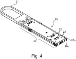
- the sample holder 20 is in Figures 4 , 5A , 5B , 6 and 7 and comprises a handle 21 for grasping the sample holder 20 during the insertion and execution of the sample holder 20 into the device 10, a body 29 and at the other end of the body 29 a module 28 in which the component 30 is located in a cavity 25 .
- Fig. 4 shows the sample holder 20 with an upper part 20o and a lower part 20u, which are assembled.
- 5A and 5B show two representations of a sectional drawing of the lower end of the sample holder 20 with the cavity 25 and thus the module 28 with the cavity 25 can be seen better.
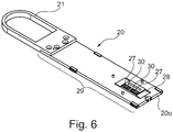
- Fig. 6 shows the lower part 20u of the sample holder 20 with the module 28 for the component 30.
- At least one feed opening 22 is made in the upper surface of the body 29.
- FIGs 4 and 5A are four feed openings 22 and in Figure 5B Two feed openings 22 are shown, the number of feed openings 22 being not restrictive for the invention.
- These feed openings 22 are in the device 10 at position 15 Arranged in such a way that the feed openings 22 are connected to the feed 40 and thus allow the temperature-controlled medium to flow into the module 28 and through the cavity 25 with the component 30.
- a discharge opening 24 is present, which enables the temperature-controlled medium to be removed from the module 28 and the cavity 25.
- This discharge opening 24 is connected to the discharge 45 ( Figure 3A and 3B ) connected in device 10 at position 15.
- the supply of the temperature-controlled medium from the supply 40 through the supply opening 22 into the module 28 and the discharge of the temperature-controlled medium through the discharge opening 24 from the module 28 to the discharge 45 thus allow the component 30 in the module 28 to flow with the temperature-controlled medium .
- Guide channels can also be attached within the module 28 in such a way that the component 30 is flowed through by the temperature-controlled medium with defined flow directions. A good and quick thermal connection of the component 30 is thereby achieved.
- the module 28 with the cavity 25 is individually and precisely aligned for the components 30. This ensures that no mechanical stresses are generated in the component 30.
- the body 29 of the sample holder 20 consists of two components 20u and 20o which are brought together to hold the component 30 in the cavity 25.
- the two components 20o and 20u each have a recess, which together form the cavity 25. It is also possible for only one of the components 20u, 20o to have the recess for the cavity 25.
- Figs. 4th , 5A , 5B and 6 show the module 28 and the cavity 25 with space for two components 30 each.
- the sample holder 20 can be constructed in such a way that the sample holder 20 could accommodate several components 30 and the number of components is therefore not restrictive for the invention
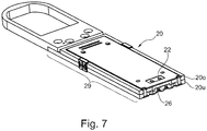
- Figure 5B shows the sample holder 20 with several connection elements 26, which in one aspect are constructed as spring contact pins and enable electrical contact with the component 30.
- the connection elements 26 conduct signals and power between the component 30 and a control and measuring device (not shown) via conductor tracks (not shown) in the sample holder 30. This allows the component 30 to be tested.
- the control device can vary the strength of the magnetic field in the device 10 and also the properties (temperature, humidity) of the temperature-controlled medium and thereby the Change environmental parameters of component 30. This means that a large number of tests can be carried out in different environments.
- the components 20 are e.g. a needle card or contacted via spring contact pins (pogo pins).
- the whole device 10 is housed in a frame which comprises moving parts e.g. Pneumatic cylinder has to push the sample holder 20 in and out of the device and to hold the two parts of the sample holder 20 together.
- moving parts e.g. Pneumatic cylinder has to push the sample holder 20 in and out of the device and to hold the two parts of the sample holder 20 together.
- FIG Fig. 8 The sequence of the method for checking and calibrating component 30 is shown in FIG Fig. 8 briefly explained.
- a first step 800 the component 30 is introduced and held in the sample holder 20. It should be noted here that holding the component 30 in the sample holder 20 does not trigger any mechanical stresses in the component 30.
- the sample holder 20 with the component 30 is inserted into the device 10 in step 810 and in step 820 the sample holder 20 is positioned at the position 15 such that the feed openings 22 of the sample holder 20 are connected to the feed 40 of the device.
- the discharge opening 24 of the sample holder 20 is also connected to the discharge 45 of the device.
- the component 30 is electrically contacted in step 830 and the component 30 is stimulated (magnetic / thermal / electrical) in step 840, so that the component 30 is characterized in step 850.
- the different environmental parameters can be changed in this step.
Landscapes
- Physics & Mathematics (AREA)
- General Physics & Mathematics (AREA)
- Condensed Matter Physics & Semiconductors (AREA)
- Health & Medical Sciences (AREA)
- Engineering & Computer Science (AREA)
- Environmental & Geological Engineering (AREA)
- Toxicology (AREA)
- Investigating Or Analyzing Materials By The Use Of Magnetic Means (AREA)
- Tests Of Electronic Circuits (AREA)
- Sampling And Sample Adjustment (AREA)
- Measuring Magnetic Variables (AREA)
Abstract
Description
- Die Erfindung betrifft eine Vorrichtung zur Prüfung und Kalibrierung eines Bauteils in einem magnetischen Feld sowie ein Verfahren zur Durchführung der Prüfung und Kalibrierung des Bauteils in dem magnetischen Feld.
- Zur Charakterisierung und Kalibrierung von Bauteilen wie Magnetfeldsensoren müssen die Bauteile unter definierten Umgebungsparametern elektrisch vermessen werden. Diese Umgebungsparameter sind z.B. die Stärke und Orientierung des Magnetfelds sowie Temperatur und Feuchtigkeit. Dabei müssen einige Herausforderungen überwunden werden. Die Umgebungsparameter müssen unabhängig voneinander sehr präzise kontrolliert werden, um zuverlässige Messergebnisse zu erhalten. Es muss eine zuverlässige, elektrische Kontaktierung des Bauteils mit einem Messgerät im gesamten Umgebungsparameterraum sichergestellt werden. Parasitäre Störeinflüsse, die sich auf die Funktion der Bauteile (Magnetfeldsensoren) auswirken können, zum Beispiel mechanische Spannungen und/oder magnetische Störfelder, sollten eliminiert werden. Die Testumgebung muss robust sein und einen möglichen hohen Durchsatz für die Anwendung in einer Produktionshalle haben.
- Vorrichtungen und Verfahren zur Prüfung und Kalibrierung des Bauteils sind an sich bekannt. Zum Beispiel zeigt die US Patentanmeldung Nr.
US 2010/0308812 A1 (Infineon) ein Testsystem mit einem Träger für ein Halbleiter-Bauteil und einen Magnetfeldgenerator in der Nähe des Trägers. In dem beschriebenen Verfahren wird das Magnetfeld durch den Magnetfeldgenerator erzeugt und die Auswirkung des Magnetfelds auf das Bauteil erfasst. - Andere Vorrichtungen und Verfahren sind den Erfindern bekannt. Diese zeigen Nachteile wie unpräzise Magnetfelder durch Verwendung von schlecht dimensionierten Spulen als Magnetfeldgeneratoren, Instabilität der erzeugten Magnetfelder durch Temperaturschwanken der Spulen in den Magnetfeldgeneratoren, unzuverlässige elektrische Kontaktierung der Bauteile, mechanische Spannung in den zu vermessenden Bauteilen, und lange Einschwingseiten für Magnetfelder und Temperatur.
- Die Erfindung liegt daher der Aufgabe zu Grunde, eine verbesserte Vorrichtung und ein verbessertes Verfahren zur Prüfung und Kalibrierung eines Bauteils zu entwickeln.
- In einem Aspekt der Erfindung umfasst die Vorrichtung einen Probenhalter mit einem Modul zur Aufnahme von mindestens einem Bauteil, mindestens einem Magnetfeldgenerator zur Erzeugung eines magnetischen Felds um den Probenhalter, und eine Zuführung zur Zuführung eines temperierten Mediums in das Modul sowie eine Abführung zur Abführung eines temperierten Mediums aus dem Modul. Bei dieser Vorrichtung befindet sich der Magnetfeldgenerator außerhalb des Bereichs, in dem die Umgebungsparameter geändert werden. Diese Trennung der Quellen der Umgebungsparameter untereinander sowie gegenüber dem Modul ermöglicht eine schnellere Änderung der Umgebungsparameter für das Bauteil, da der Magnetfeldgenerator auch nicht erwärmt werden muss, wie in dem Stand der Technik bekannt. Lediglich die Temperatur des kleineren Moduls mit dem Bauteil muss geändert werden. Die Umgebungstemperatur des Magnetfeldgenerators bleibt somit weitgehend konstant und daher ist das Magnetfeld auch stabil. Das relativ kleine Modul mit dem/den Bauteil(-en) kann auch schnell erwärmt und abgekühlt werden.
- Der Probenhalter hat mindestens eine Einführöffnung zur Weiterführung des temperierten Mediums von der Zuführung in einen Hohlraum in dem Modul und mindestens eine Abführöffnung des temperierten Mediums aus dem Hohlraum des Moduls zu der Abführung. Das Bauteil oder die Bauteile sind zwischen der Einführöffnung und der Abführöffnung in dem Hohlraum angeordnet, damit es/sie von dem temperierten Medium angeströmt wird/werden.
- In einem Aspekt der Erfindung besteht der Probenhalter mit dem Modul aus zwei Teilen. Der Hohlraum ist durch gegenüberliegende Aussparungen in den zwei Teilen oder in einem der zwei Teile gebildet. Durch Zusammenbringung der zwei Teile wird das Bauelement in dem Hohlraum positioniert und kann zuverlässig festgehalten und elektrisch kontaktiert werden.
- Der Magnetfeldgenerator umfasst eine Mehrzahl von Spulen, die orthogonal zueinander angeordnet sind. In einem Aspekt sind die Spulen als Helmholtz-Spulen aufgebaut und das erzeugte magnetische Feld ist somit weitgehend homogen entlang der Achse der Helmholtz-Spulen. Das Bauteil ist in einem weitgehend homogenen Bereich rund um die gemeinsamen Achsen der Spulen angeordnet.
- Der Probenhalter weist mehrere Anschlusselemente in dem Hohlraum zum Kontaktieren des Bauteils auf. Diese Anschlusselemente sind vorzugsweise als Federkontaktstifte ausgebildet und kontaktieren das Bauteil bei Zusammenbringen der zwei Teile des Probenhalters.
- Der Probenhalter kann auch Führungskanäle in dem Modul und Hohlraum aufweisen, welche das temperierte Medium um das Bauteil herumleiten.
- Ein Steuerungs- und Messgerät zur Steuerung der Vorrichtung mit dem temperierten Medium und dem Magnetfeld sowie zur Evaluierung der Messdaten ist auch vorhanden.
- Das Verfahren zur Prüfung und Kalibrierung des Bauteils umfasst die Einführung eines Probenhalters mit einem in einem Modul montierten Bauteil in ein magnetisches Feld. Danach wird eine Zuführung an eine Zuführöffnung in dem Probenhalter und eine Abführung an eine Abführöffnung in dem Probenhalter gebracht. Anschließend wird das Modul mit einem temperierten Medium von der Zuführung zu der Abführung angeströmt. Wie oben aufgeführt wird das temperierte Medium nur durch das relativ kleine Modul durchgeführt. Somit können die Umgebungsparameter schneller geändert werden.
- Die Erfindung wird nun anhand der Zeichnungen näher erläutert. Es zeigen:
-
Fig. 1 eine perspektivische Darstellung der Vorrichtung von einer ersten Seite; -
Fig. 2 eine perspektivische Darstellung der Vorrichtung von der anderen Seite; -
Fig. 3A eine Seitenansicht der Vorrichtung undFig. 3B eine Schnittzeichnung der Vorrichtung von der gleichen Position; -
Fig. 4 eine Zeichnung eines Probenhalters; -
Fig. 5A und 5B eine Schnittzeichnung des Endes des Probenhalters; -
Fig. 6 das untere Teil des Probenhalters; -
Fig. 7 eine Schnittzeichnung des Probenhalters mit elektrischen Anschlusselementen; -
Fig. 8 einen Ablauf des Verfahrens. -
Fig. 1 und2 zeigen zwei perspektivische Darstellungen einer Vorrichtung 10 zur Prüfung und Kalibrierung mindestens eines Bauteils 30, das in einem Probenhalter 20 aufgenommen ist. DieFiguren 3A und3B zeigen eine Seitenansicht der gleichen Vorrichtung 10, wobei dieFig. 3A das externe Aussehen der Vorrichtung 10 undFig. 3B eine Schnittdarstellung mit dem Innenleben der Vorrichtung 10 zeigt. In denFiguren 1 und2 ist das Bauteil 30 nicht erkennbar, da das Bauteil 30 sich innerhalb der Vorrichtung 10 befindet. Der Probenhalter 20 ist in denFiguren 4 ,5A ,5B ,6 und7 detaillierter dargestellt und wird später näher beschrieben.Figs. 2 und3B zeigen den Probenhalter 20 montiert in der Vorrichtung 10. - Die Vorrichtung 10 weist einen Magnetfeldgenerator auf, der in
Fig. 1 und2 aus insgesamt zehn paarweise angeordneten Spulen besteht. In den Zeichnungen sind nur drei Spulenpaare 60a, 60b und 60c zu erkennen. Zwei weitere Spulenpaare sind innerhalb des Magnetfeldgenerators in der gleichen Ausrichtung wie das Spulenpaar 60c angeordnet. Jedes Spulenpaar ist vorzugsweise in einer Art "Helmholtz"-Anordnung mit einem weitgehend homogenen magnetischen Feld in der Nähe seiner Spulenachse ausgebildet. Die Spulenpaare 60a, 60b und 60c sind jeweils orthogonal zueinander angeordnet und ihre Achsen weisen einen gemeinsamen Schnittpunkt 15 (dargestellt in der SchnittansichtFig. 3B ) auf. Das Bauteil 30 ist in der Vorrichtung 10 so angebracht, dass es sich weitgehend an dem oder um den Schnittpunkt 15 an der Kreuzung der Spulenachsen der Spulenpaare 60a, 60b und 60c befindet. An diesem Schnittpunkt15 ist daher das durch die Spulenpaare 60a, 60b und 60c erzeugte magnetische Feld in allen Richtungen weitgehend homogen. - Die Vorrichtung 10 verfügt über eine Zuführung 40 und eine Abführung 45, welche jeweils ein temperiertes Medium in die Vorrichtung 10 hineinleiten und aus der Vorrichtung 10 herausleiten. Das temperierte Medium ist zum Beispiel Luft bei einer vorbestimmten Temperatur und Feuchtigkeit. Aus
Fig. 3B ist zu erkennen, dass die Zuführung 40 das temperierte Medium an das Bauteil 30 zuführt und die Abführung 45 das temperierte Medium ableitet. Die Abführung 45 ist mit einer nicht dargestellten Entsorgungsvorrichtung verbunden. Das temperierte Medium könnte auch ein anderes Gas z.B. ein Edelgas sein. - Der Probenhalter 20 kann in die Vorrichtung 10 durch eine Halteröffnung 17 ein- und ausgeführt werden. Diese Ein- und Ausführung kann automatisch oder manuell erfolgen. In einem weiteren Aspekt ist der Probenhalter 20 Teil eines Leadframes (Anschlussrahmens) mit einer Mehrzahl von Bauteilen 30, der durch die Halteröffnung 17 in der Vorrichtung 10 in einem kontinuierlichen oder semi-kontinuierlichen Verfahren durchgezogen wird. Der Leadframe kann zum Beispiel Bauteile in Abschnitten von 8 x 20 Bauteilen aufweisen, wobei diese Größe nicht limitierend für die Erfindung ist.
- Der Probenhalter 20 ist in
Figuren 4 ,5A ,5B ,6 und7 dargestellt und umfasst einen Griff 21 zur Erfassung des Probenhalters 20 bei der Ein- und Ausführung des Probenhalters 20 in die Vorrichtung 10, einen Körper 29 und am anderen Ende des Körpers 29 ein Modul 28, in dem sich das Bauteil 30 in einem Hohlraum 25 befindet. -
Fig. 4 zeigt den Probenhalter 20 mit einem oberen Teil 20o und einem unteren Teil 20u, die zusammengesetzt sind.Fig. 5A und 5B zeigen zwei Darstellungen einer Schnittzeichnung des unteren Endes des Probenhalters 20 mit dem Hohlraum 25 und lässt somit das Modul 28 mit dem Hohlraum 25 besser erkennen.Fig. 6 zeigt das untere Teil 20u des Probenhalters 20 mit dem Modul 28 für das Bauteil 30. - Mindestens eine Zuführöffnung 22 ist in der oberen Fläche des Körpers 29 eingebracht. In den
Figuren 4 und5A sind vier Zuführöffnungen 22 und inFig. 5B sind zwei Zuführöffnungen 22 dargestellt, wobei die Anzahl der Zuführöffnungen 22 nicht einschränkend für die Erfindung ist. Diese Zuführöffnungen 22 sind in der Vorrichtung 10 bei der Position 15 so angeordnet, dass die Zuführöffnungen 22 mit der Zuführung 40 verbunden sind und somit die Anströmung des temperierten Mediums in das Modul 28 und durch den Hohlraum 25 mit dem Bauteil 30 ermöglicht. - In der unteren Fläche ist in
Fig. 5A zu sehen, dass eine Abführöffnung 24 vorhanden ist, welche die Abführung des temperierten Mediums aus dem Modul 28 und Hohlraum 25 ermöglicht. Diese Abführöffnung 24 ist mit der Abführung 45 (Fig. 3A und3B ) in der Vorrichtung 10 bei der Position 15 verbunden. Die Zuführung des temperierten Mediums von der Zuführung 40 durch die Zuführöffnung 22 in das Modul 28 und die Abführung des temperierten Mediums durch die Abführöffnung 24 aus dem Modul 28 an die Abführung 45 ermöglichen somit ein Anströmen des Bauteils 30 in dem Modul 28 mit dem temperierten Medium. - Innerhalb des Moduls 28 können auch Führungskanäle so angebracht werden, dass das Bauteil 30 durch das temperierte Medium mit definierten Stromrichtungen angeströmt wird. Dadurch wird eine gute und schelle thermische Anbindung des Bauteils 30 erreicht.
- Das Modul 28 mit dem Hohlraum 25 ist individuell und passgenau für die Bauteile 30 ausgerichtet. Dies stellt sicher, dass keine mechanischen Spannungen in dem Bauteil 30 erzeugt werden.
- Aus
Figs. 5A, 5B und6 ist zu erkennen, dass der Körper 29 des Probenhalters 20 aus zwei Bestandteilen 20u und 20o besteht, die aneinander gebracht werden, um das Bauteil 30 in dem Hohlraum 25 zu halten. Natürlich sind andere Verfahren zum Festhalten des Bauteils 30 möglich. Die zwei Bestandteile 20o und 20u weisen jeweils eine Aussparung auf, welche gemeinsam den Hohlraum 25 bilden. Es ist auch möglich, dass nur eines der Bestandteile 20u, 20o die Aussparung für den Hohlraum 25 aufweist. -
Figs. 4 ,5A ,5B und6 zeigen das Modul 28 und den Hohlraum 25 mit Platz für jeweils zwei Bauteile 30. Der Probenhalter 20 kann so gebaut werden, dass der Probenhalter 20 mehrere Bauteile 30 aufnehmen könnte und die Anzahl der Bauteile ist somit nicht einschränkend für die Erfindung -
Fig. 5B zeigt den Probenhalter 20 mit mehreren Anschlusselementen 26, die in einem Aspekt als Federkontaktstifte aufgebaut sind und den elektrischen Kontakt mit dem Bauteil 30 ermöglichen. Die Anschlusselemente 26 leiten Signale und Leistung zwischen dem Bauteil 30 und einem nicht dargestellten Steuerungs- und Messgerät über (nicht dargestellten) Leiterbahnen in dem Probenhalter 30. Dadurch kann das Bauteil 30 geprüft werden. Das Steuerungsgerät kann die Stärke des Magnetfelds in der Vorrichtung 10 variieren und auch die Eigenschaften (Temperatur, Feuchtigkeit) des temperierten Mediums und dabei die Umgebungsparameter des Bauteils 30 ändern. Somit lassen sich eine Vielzahl von Tests in unterschiedlichen Umgebungen durchführen. - In dem weiteren Aspekt mit einem Leadframe werden die Bauteile 20 über z.B. eine Nadelkarte oder über Federkontaktstifte (Pogo-Pins) kontaktiert.
- Die ganze Vorrichtung 10 ist in einem Rahmen untergebracht, welcher bewegliche Teile z.B. Pneumatik-Zylinder aufweist, um den Probenhalter 20 in die Vorrichtung ein- und auszuschieben sowie um die zwei Teile des Probenhalters 20 zusammen zu halten.
- Der Ablauf des Verfahrens zur Prüfung und Kalibrierung des Bauteils 30 ist in
Fig. 8 kurz erläutert. In einem ersten Schritt 800 wird das Bauteil 30 in den Probenhalter 20 eingebracht und gehalten. Es ist dabei zu beachten, dass das Festhalten des Bauteils 30 in dem Probenhalter 20 keine mechanischen Spannungen in dem Bauteil 30 auslöst. - Der Probenhalter 20 mit dem Bauteil 30 wird in die Vorrichtung 10 eingeführt im Schritt 810 und im Schritt 820 wird der Probenhalter 20 so positioniert an der Position 15, dass die Zuführöffnungen 22 des Probenhalters 20 mit der Zuführung 40 der Vorrichtung verbunden sind. Ebenfalls ist die Abführöffnung 24 des Probenhalters 20 mit der Abführung 45 der Vorrichtung verbunden. Das Bauteil 30 wird im Schritt 830 elektrisch kontaktiert und im Schritt 840 wird das Bauteil 30 stimuliert (magnetisch / thermisch / elektrisch), damit das Bauteil 30 im Schritt 850 charakterisiert wird. Dabei können die unterschiedlichen Umgebungsparameter (Temperatur, Feuchte, Feldstärke) in dem Schritt geändert werden.
-
- 10
- Vorrichtung
- 15
- gemeinsamer Schnittpunkt der Spulenachsen
- 17
- Halteröffnung
- 20
- Probenhalter
- 20o
- Oberes Teil
- 20u
- Unteres Teil
- 21
- Griff
- 22
- Zuführöffnung
- 24
- Abführöffnung
- 25
- Hohlraum
- 26
- Anschlusselemente
- 28
- Modul
- 29
- Körper
- 30
- Bauteil
- 40
- Zuführung
- 45
- Abführung
- 60a, 60b, 60c
- Spulenpaare
Claims (23)
- Vorrichtung (10) zur Prüfung und/oder Kalibrierung eines Bauteils (30) umfassend:einen Probenhalter (20) mit einem Modul (28) zur Aufnahme von mindestens einem Bauteil (30);mindestens einen Magnetfeldgenerator (60a, 60b, 60c) zur Erzeugung eines magnetischen Felds (45) um das Modul (28);eine Zuführung (40) zur Zuführung eines temperierten Mediums in das Modul (25); undeine Abführung (45) zur Abführung eines temperierten Mediums aus dem Modul (28).
- Vorrichtung (10) nach Anspruch 1, wobei der Probenhalter (20) mindestens eine Einführöffnung (22) zur Weiterführung des temperierten Mediums von der Zuführung (40) in das Modul (28) und mindestens eine Abführöffnung (24) des temperierten Mediums aus dem Modul (28) zu der Abführung (45) aufweist und
wobei das mindesten eine Bauteil (30) zwischen der Einführöffnung (22) und der Abführöffnung (24) angeordnet ist. - Vorrichtung (10) nach einem der vorhergehenden Ansprüche, wobei der Probenhalter (20) aus zwei Teilen (20o, 20u) besteht und ein Hohlraum (25) in dem Modul (28) entweder durch gegenüberliegende Aussparungen in den zwei Teilen (20o, 20u) gebildet ist oder in einem der zwei Teile (20o, 20u) geformt ist.
- Vorrichtung (10) nach einem der Ansprüche 1 bis 3, weiter umfassend ein bewegliches Element zum Zusammenpressen der zwei Teile des Probenhalters (20).
- Vorrichtung (10) nach einem der vorhergehenden Ansprüche, wobei die Zuführung (40) und die Abführung (45) derart angeordnet sind, dass der Probenhalter (20) zwischen der Zuführung (40) und der Abführung (45) positionierbar ist.
- Vorrichtung (10) nach einem der vorhergehenden Ansprüche, wobei der Magnetfeldgenerator (60a, 60b, 60c) eine Mehrzahl von Spulen umfasst.
- Vorrichtung (10) nach Anspruch 6, wobei die Spulen (60a, 60b, 60c) orthogonal zueinander angeordnet sind.
- Vorrichtung (10) nach einem der vorhergehenden Ansprüche, wobei der Magnetfeldgenerator (60a, 60b, 60c) als eine Art Helmholtz-Spulensystem gebaut ist und das erzeugte magnetische Feld weitgehend homogen ist.
- Vorrichtung (10) nach einem der Ansprüche 6 bis 8, wobei die der Magnetfeldgenerator (60a, 60b, 60c) eine Vielzahl von Paaren von Spulen (60a, 60b, 60c) um das Modul (28) umfasst.
- Vorrichtung (10) nach einem der Ansprüche 6 bis 9, wobei das mindestens eine Bauteil (30) auf/um den gemeinsamen Schnittpunkt (15) der Achsen der Spulen (60a, 60b, 60c) angeordnet ist.
- Vorrichtung nach einem der Ansprüche 1 bis 10, wobei der Probenhalter (20) mehrere Anschlusselemente (26) zum Kontaktieren des Bauteils (30) aufweist.
- Vorrichtung nach Anspruch 11, weiter umfassend mehrere bewegbare Kontaktstifte zum Kontaktieren des Probenhalters (20).
- Vorrichtung nach einem der vorhergehenden Ansprüche, wobei der Probenhalter (20) Führungskanäle (27) aufweist, welche das temperierte Medium um das Bauteil (30) leiten.
- Vorrichtung (10) nach einem der vorhergehenden Ansprüche, wobei das mindestens eine Bauteil (30) Kontaktdrähte aufweist, die von dem temperierten Medium umströmt werden.
- Vorrichtung (10) nach einem der vorhergehenden Ansprüche, weiter umfassend ein Steuerungsgerät zur Temperatursteuerung des temperierten Mediums.
- Verfahren zur Prüfung und Kalibrierung eines Bauteils (30) in einer Vorrichtung (10) umfassend:Einführen (810) eines Probenhalters (20) mit einem in einem Hohlraum (25) montierten Bauteil (30) in ein magnetisches Feld;Anbringen (820) einer Zuführung(40) an eine Zuführöffnung (22) in dem Probenhalter (20);Anbringen (820) einer Abführung (45) an eine Abführöffnung (24) in dem Probenhalter (20);Stimulieren (840) der Bauteile (30) im Hohlraum (25).
- Verfahren nach Anspruch 16 umfassend
Ändern der Umgebungsparameter. - Verfahren nach Anspruch 16 oder 17, weiter umfassend
Kontaktieren (830) des Bauteils und Durchführen einer Charakterisierung (850) - Verfahren nach einem der Ansprüche 16 bis 18, weiter umfassend das Durchführung des Probenhalters (20) durch die Vorrichtung (10) in einem kontinuierlichen Verfahren.
- Probenhalter (20) umfassend
einen oberen Teil (20o) und eine Einführöffnung (22); und
einen unteren Teil (20u) und eine Ausführöffnung (24);
wobei die obere Aussparung (25a) und die untere Aussparung (25u) bei Zusammenfügung des oberen Teils (20o) mit dem unteren Teil (20u) einen Hohlraum (25) zur Aufnahme eines Bauteils (30) bilden, und
wobei das Bauteil (30) in dem Hohlraum (25) derart angeordnet ist, dass ein temperiertes Medium durch den Hohlraum (25) um das Bauteil (25) strömt. - Probenhalter (20) nach Anspruch 19, wobei das obere Teil (20o) eine Aussparung und/oder das untere Teil (20u) eine Aussparung aufweist und der Hohlraum (25) durch mindestens eine der Aussparungen gebildet ist.
- Probenhalte (20) nach Anspruch 19 oder 20, wobei der Probenhalter (20) Führungskanäle (27) zur Lenkung des temperierten Mediums um das Bauteil (30) aufweist.
- Probenhalter (20) nach einem der Ansprüche 19 bis 21, weiter umfassend Anschlusselemente (26) zum elektrischen Kontaktieren des Bauteils (30).
Applications Claiming Priority (1)
| Application Number | Priority Date | Filing Date | Title |
|---|---|---|---|
| DE102018132940.7A DE102018132940B4 (de) | 2018-12-19 | 2018-12-19 | Vorrichtung und Verfahren zur Prüfung und Kalibrierung eines Bauteils |
Publications (2)
| Publication Number | Publication Date |
|---|---|
| EP3671246A1 true EP3671246A1 (de) | 2020-06-24 |
| EP3671246B1 EP3671246B1 (de) | 2024-04-10 |
Family
ID=68917504
Family Applications (1)
| Application Number | Title | Priority Date | Filing Date |
|---|---|---|---|
| EP19216375.6A Active EP3671246B1 (de) | 2018-12-19 | 2019-12-16 | Vorrichtung und verfahren zur prüfung und kalibrierung eines bauteils |
Country Status (4)
| Country | Link |
|---|---|
| US (1) | US11131722B2 (de) |
| EP (1) | EP3671246B1 (de) |
| CN (1) | CN111505554A (de) |
| DE (1) | DE102018132940B4 (de) |
Families Citing this family (1)
| Publication number | Priority date | Publication date | Assignee | Title |
|---|---|---|---|---|
| EP3620752A1 (de) * | 2018-09-05 | 2020-03-11 | Sword Health, S.A. | Verfahren und system zur kalibrierung von sensoren |
Citations (5)
| Publication number | Priority date | Publication date | Assignee | Title |
|---|---|---|---|---|
| US6191599B1 (en) * | 1998-10-09 | 2001-02-20 | International Business Machines Corporation | IC device under test temperature control fixture |
| US20100308812A1 (en) | 2007-09-26 | 2010-12-09 | Wolfgang Marbler | Test Systems and Methods for Semiconductor Devices |
| US20130008628A1 (en) * | 2011-07-08 | 2013-01-10 | Titan Semiconductor Tool, LLC | Thermal chamber for ic chip testing |
| US20130038321A1 (en) * | 2011-08-10 | 2013-02-14 | Yamaha Corporation | Inspection apparatus and inspection method of magnetic sensor |
| CN106871948A (zh) * | 2016-12-27 | 2017-06-20 | 中国船舶重工集团公司第七研究所 | 一种磁电子器件校准装置 |
Family Cites Families (8)
| Publication number | Priority date | Publication date | Assignee | Title |
|---|---|---|---|---|
| US7064953B2 (en) * | 2001-12-27 | 2006-06-20 | Formfactor, Inc. | Electronic package with direct cooling of active electronic components |
| US7996057B2 (en) * | 2007-01-31 | 2011-08-09 | Biosense Webster, Inc. | Ultrasound catheter calibration with enhanced accuracy |
| DE102007038754A1 (de) * | 2007-08-16 | 2009-02-19 | Giesecke & Devrient Gmbh | Vorrichtung für die Kalibrierung von Sensoren |
| US8560713B2 (en) | 2008-07-31 | 2013-10-15 | Sap Ag | Method and system for mediating enterprise service access for smart devices |
| CN201259748Y (zh) * | 2008-08-01 | 2009-06-17 | 北京科技大学 | 一种磁场特性、磁敏元件综合实验仪器 |
| WO2010103419A1 (en) * | 2009-03-09 | 2010-09-16 | Koninklijke Philips Electronics N.V. | Arrangement and method for measuring a magnetic material in a region of action |
| JP5854736B2 (ja) * | 2011-09-30 | 2016-02-09 | キヤノン株式会社 | 核磁気共鳴イメージング装置及び核磁気共鳴イメージング方法 |
| US10509086B2 (en) * | 2015-06-12 | 2019-12-17 | Koninklijke Philips N.V. | Magnetic resonance fingerprinting dictionary generation using a supplementary magnetic field coil |
-
2018
- 2018-12-19 DE DE102018132940.7A patent/DE102018132940B4/de active Active
-
2019
- 2019-12-16 EP EP19216375.6A patent/EP3671246B1/de active Active
- 2019-12-18 US US16/718,787 patent/US11131722B2/en active Active
- 2019-12-19 CN CN201911320492.1A patent/CN111505554A/zh active Pending
Patent Citations (5)
| Publication number | Priority date | Publication date | Assignee | Title |
|---|---|---|---|---|
| US6191599B1 (en) * | 1998-10-09 | 2001-02-20 | International Business Machines Corporation | IC device under test temperature control fixture |
| US20100308812A1 (en) | 2007-09-26 | 2010-12-09 | Wolfgang Marbler | Test Systems and Methods for Semiconductor Devices |
| US20130008628A1 (en) * | 2011-07-08 | 2013-01-10 | Titan Semiconductor Tool, LLC | Thermal chamber for ic chip testing |
| US20130038321A1 (en) * | 2011-08-10 | 2013-02-14 | Yamaha Corporation | Inspection apparatus and inspection method of magnetic sensor |
| CN106871948A (zh) * | 2016-12-27 | 2017-06-20 | 中国船舶重工集团公司第七研究所 | 一种磁电子器件校准装置 |
Also Published As
| Publication number | Publication date |
|---|---|
| EP3671246B1 (de) | 2024-04-10 |
| DE102018132940A1 (de) | 2020-06-25 |
| US20200200836A1 (en) | 2020-06-25 |
| DE102018132940B4 (de) | 2024-08-01 |
| US11131722B2 (en) | 2021-09-28 |
| CN111505554A (zh) | 2020-08-07 |
Similar Documents
| Publication | Publication Date | Title |
|---|---|---|
| DE19821194B4 (de) | Halbleiterbauelement-Testgerät | |
| EP2210115B1 (de) | Vollrasterkassette für einen paralleltester zum testen einer unbestückten leiterplatte, federkontaktstift für eine solche vollrasterkassette sowie adapter für einen paralleltester zum testen einer unbestückten leiterplatte | |
| DE112006001477B4 (de) | Testsondenkarte | |
| DE2063198A1 (de) | Elektrische Prüfeinrichtung | |
| DE20320996U1 (de) | Prüfkopf für kombinierte Signale | |
| DE10304881A1 (de) | Verfahren und Vorrichtung für die Verwaltung von Kräften in einer drahtlosen Haltevorrichtung | |
| DE10044408A1 (de) | Pinblockstruktur zur Halterung von Anschlußpins | |
| EP3545729A1 (de) | Leiterplatte und verfahren zur herstellung der leiterplatte | |
| DE10039928A1 (de) | Vorrichtung zum automatisierten Testen, Kalibrieren und Charakterisieren von Testadaptern | |
| DE19946458C2 (de) | Vorrichtung und Verfahren zur Charakterisierung von Sphäroiden | |
| DE602004009662T2 (de) | Kontaktstift für einen Prüfkopf | |
| EP3671246A1 (de) | Vorrichtung und verfahren zur prüfung und kalibrierung eines bauteils | |
| DE102015102636B4 (de) | Prüfkammer und Verfahren für die EMV-Meßprüfung | |
| DE10260238B4 (de) | Adapter zum Testen einer oder mehrerer Leiteranordnungen und Verfahren | |
| DE4320109A1 (de) | Universeller Sondenadapter | |
| DE3839539A1 (de) | Multikompatible halteeinrichtung fuer zu pruefende leiterplatten bzw. flachbaugruppen, und fuer kontaktstift-traegerplatten und niederhalteplatten zur verwendung in pruefgeraeten | |
| DE2656263A1 (de) | Vorrichtung zur messung bestimmter eigenschaften von in einem medium suspendierten partikeln | |
| DE60319780T2 (de) | Vorrichtung zum Testen von Anschlussdrähten | |
| EP2033002A1 (de) | Kontaktiervorrichtung zum testen von elektronischen bauelementen unter bestimmten temperaturbedingungen | |
| DE102004033999A1 (de) | Verfahren zum Testen der Funktionalität von elektronischen Schaltelementen einer Leiterplatte sowie Adapterleiterplatte und Vorrichtung zur Durchführung des Verfahrens | |
| DE4313962C1 (de) | Vorrichtung für den automatischen Test von hochintegrierten Baugruppen | |
| DE102014117300B4 (de) | Anordnung und Verfahren zur Vermessung einer elektronischen Struktur | |
| DE112023005751T5 (de) | Sondenmodul und dasselbe aufweisendes mikrosondensystem | |
| DE68911227T2 (de) | Anschlusssystem für eine Testeinrichtung von gedruckten Schaltungsplatten. | |
| EP2674770A1 (de) | Vorrichtung und Verfahren zum Prüfen von elektronischen Bauteilelementen auf einem Träger oder einem Substrat |
Legal Events
| Date | Code | Title | Description |
|---|---|---|---|
| PUAI | Public reference made under article 153(3) epc to a published international application that has entered the european phase |
Free format text: ORIGINAL CODE: 0009012 |
|
| STAA | Information on the status of an ep patent application or granted ep patent |
Free format text: STATUS: THE APPLICATION HAS BEEN PUBLISHED |
|
| AK | Designated contracting states |
Kind code of ref document: A1 Designated state(s): AL AT BE BG CH CY CZ DE DK EE ES FI FR GB GR HR HU IE IS IT LI LT LU LV MC MK MT NL NO PL PT RO RS SE SI SK SM TR |
|
| AX | Request for extension of the european patent |
Extension state: BA ME |
|
| STAA | Information on the status of an ep patent application or granted ep patent |
Free format text: STATUS: REQUEST FOR EXAMINATION WAS MADE |
|
| 17P | Request for examination filed |
Effective date: 20201021 |
|
| RBV | Designated contracting states (corrected) |
Designated state(s): AL AT BE BG CH CY CZ DE DK EE ES FI FR GB GR HR HU IE IS IT LI LT LU LV MC MK MT NL NO PL PT RO RS SE SI SK SM TR |
|
| STAA | Information on the status of an ep patent application or granted ep patent |
Free format text: STATUS: EXAMINATION IS IN PROGRESS |
|
| 17Q | First examination report despatched |
Effective date: 20220324 |
|
| GRAP | Despatch of communication of intention to grant a patent |
Free format text: ORIGINAL CODE: EPIDOSNIGR1 |
|
| STAA | Information on the status of an ep patent application or granted ep patent |
Free format text: STATUS: GRANT OF PATENT IS INTENDED |
|
| INTG | Intention to grant announced |
Effective date: 20231124 |
|
| RAP3 | Party data changed (applicant data changed or rights of an application transferred) |
Owner name: TDK-MICRONAS GMBH |
|
| P01 | Opt-out of the competence of the unified patent court (upc) registered |
Effective date: 20231201 |
|
| GRAS | Grant fee paid |
Free format text: ORIGINAL CODE: EPIDOSNIGR3 |
|
| GRAA | (expected) grant |
Free format text: ORIGINAL CODE: 0009210 |
|
| STAA | Information on the status of an ep patent application or granted ep patent |
Free format text: STATUS: THE PATENT HAS BEEN GRANTED |
|
| AK | Designated contracting states |
Kind code of ref document: B1 Designated state(s): AL AT BE BG CH CY CZ DE DK EE ES FI FR GB GR HR HU IE IS IT LI LT LU LV MC MK MT NL NO PL PT RO RS SE SI SK SM TR |
|
| REG | Reference to a national code |
Ref country code: GB Ref legal event code: FG4D Free format text: NOT ENGLISH |
|
| REG | Reference to a national code |
Ref country code: CH Ref legal event code: EP |
|
| REG | Reference to a national code |
Ref country code: DE Ref legal event code: R096 Ref document number: 502019011010 Country of ref document: DE |
|
| REG | Reference to a national code |
Ref country code: IE Ref legal event code: FG4D Free format text: LANGUAGE OF EP DOCUMENT: GERMAN |
|
| REG | Reference to a national code |
Ref country code: LT Ref legal event code: MG9D |
|
| REG | Reference to a national code |
Ref country code: NL Ref legal event code: MP Effective date: 20240410 |
|
| PG25 | Lapsed in a contracting state [announced via postgrant information from national office to epo] |
Ref country code: NL Free format text: LAPSE BECAUSE OF FAILURE TO SUBMIT A TRANSLATION OF THE DESCRIPTION OR TO PAY THE FEE WITHIN THE PRESCRIBED TIME-LIMIT Effective date: 20240410 |
|
| PG25 | Lapsed in a contracting state [announced via postgrant information from national office to epo] |
Ref country code: NL Free format text: LAPSE BECAUSE OF FAILURE TO SUBMIT A TRANSLATION OF THE DESCRIPTION OR TO PAY THE FEE WITHIN THE PRESCRIBED TIME-LIMIT Effective date: 20240410 |
|
| PG25 | Lapsed in a contracting state [announced via postgrant information from national office to epo] |
Ref country code: IS Free format text: LAPSE BECAUSE OF FAILURE TO SUBMIT A TRANSLATION OF THE DESCRIPTION OR TO PAY THE FEE WITHIN THE PRESCRIBED TIME-LIMIT Effective date: 20240810 |
|
| PG25 | Lapsed in a contracting state [announced via postgrant information from national office to epo] |
Ref country code: BG Free format text: LAPSE BECAUSE OF FAILURE TO SUBMIT A TRANSLATION OF THE DESCRIPTION OR TO PAY THE FEE WITHIN THE PRESCRIBED TIME-LIMIT Effective date: 20240410 |
|
| PG25 | Lapsed in a contracting state [announced via postgrant information from national office to epo] |
Ref country code: FI Free format text: LAPSE BECAUSE OF FAILURE TO SUBMIT A TRANSLATION OF THE DESCRIPTION OR TO PAY THE FEE WITHIN THE PRESCRIBED TIME-LIMIT Effective date: 20240410 Ref country code: HR Free format text: LAPSE BECAUSE OF FAILURE TO SUBMIT A TRANSLATION OF THE DESCRIPTION OR TO PAY THE FEE WITHIN THE PRESCRIBED TIME-LIMIT Effective date: 20240410 |
|
| PG25 | Lapsed in a contracting state [announced via postgrant information from national office to epo] |
Ref country code: GR Free format text: LAPSE BECAUSE OF FAILURE TO SUBMIT A TRANSLATION OF THE DESCRIPTION OR TO PAY THE FEE WITHIN THE PRESCRIBED TIME-LIMIT Effective date: 20240711 |
|
| PG25 | Lapsed in a contracting state [announced via postgrant information from national office to epo] |
Ref country code: PT Free format text: LAPSE BECAUSE OF FAILURE TO SUBMIT A TRANSLATION OF THE DESCRIPTION OR TO PAY THE FEE WITHIN THE PRESCRIBED TIME-LIMIT Effective date: 20240812 |
|
| PG25 | Lapsed in a contracting state [announced via postgrant information from national office to epo] |
Ref country code: ES Free format text: LAPSE BECAUSE OF FAILURE TO SUBMIT A TRANSLATION OF THE DESCRIPTION OR TO PAY THE FEE WITHIN THE PRESCRIBED TIME-LIMIT Effective date: 20240410 |
|
| PG25 | Lapsed in a contracting state [announced via postgrant information from national office to epo] |
Ref country code: PL Free format text: LAPSE BECAUSE OF FAILURE TO SUBMIT A TRANSLATION OF THE DESCRIPTION OR TO PAY THE FEE WITHIN THE PRESCRIBED TIME-LIMIT Effective date: 20240410 |
|
| PG25 | Lapsed in a contracting state [announced via postgrant information from national office to epo] |
Ref country code: LV Free format text: LAPSE BECAUSE OF FAILURE TO SUBMIT A TRANSLATION OF THE DESCRIPTION OR TO PAY THE FEE WITHIN THE PRESCRIBED TIME-LIMIT Effective date: 20240410 |
|
| PG25 | Lapsed in a contracting state [announced via postgrant information from national office to epo] |
Ref country code: PT Free format text: LAPSE BECAUSE OF FAILURE TO SUBMIT A TRANSLATION OF THE DESCRIPTION OR TO PAY THE FEE WITHIN THE PRESCRIBED TIME-LIMIT Effective date: 20240812 Ref country code: PL Free format text: LAPSE BECAUSE OF FAILURE TO SUBMIT A TRANSLATION OF THE DESCRIPTION OR TO PAY THE FEE WITHIN THE PRESCRIBED TIME-LIMIT Effective date: 20240410 Ref country code: NO Free format text: LAPSE BECAUSE OF FAILURE TO SUBMIT A TRANSLATION OF THE DESCRIPTION OR TO PAY THE FEE WITHIN THE PRESCRIBED TIME-LIMIT Effective date: 20240710 Ref country code: LV Free format text: LAPSE BECAUSE OF FAILURE TO SUBMIT A TRANSLATION OF THE DESCRIPTION OR TO PAY THE FEE WITHIN THE PRESCRIBED TIME-LIMIT Effective date: 20240410 Ref country code: IS Free format text: LAPSE BECAUSE OF FAILURE TO SUBMIT A TRANSLATION OF THE DESCRIPTION OR TO PAY THE FEE WITHIN THE PRESCRIBED TIME-LIMIT Effective date: 20240810 Ref country code: HR Free format text: LAPSE BECAUSE OF FAILURE TO SUBMIT A TRANSLATION OF THE DESCRIPTION OR TO PAY THE FEE WITHIN THE PRESCRIBED TIME-LIMIT Effective date: 20240410 Ref country code: GR Free format text: LAPSE BECAUSE OF FAILURE TO SUBMIT A TRANSLATION OF THE DESCRIPTION OR TO PAY THE FEE WITHIN THE PRESCRIBED TIME-LIMIT Effective date: 20240711 Ref country code: FI Free format text: LAPSE BECAUSE OF FAILURE TO SUBMIT A TRANSLATION OF THE DESCRIPTION OR TO PAY THE FEE WITHIN THE PRESCRIBED TIME-LIMIT Effective date: 20240410 Ref country code: ES Free format text: LAPSE BECAUSE OF FAILURE TO SUBMIT A TRANSLATION OF THE DESCRIPTION OR TO PAY THE FEE WITHIN THE PRESCRIBED TIME-LIMIT Effective date: 20240410 Ref country code: BG Free format text: LAPSE BECAUSE OF FAILURE TO SUBMIT A TRANSLATION OF THE DESCRIPTION OR TO PAY THE FEE WITHIN THE PRESCRIBED TIME-LIMIT Effective date: 20240410 Ref country code: RS Free format text: LAPSE BECAUSE OF FAILURE TO SUBMIT A TRANSLATION OF THE DESCRIPTION OR TO PAY THE FEE WITHIN THE PRESCRIBED TIME-LIMIT Effective date: 20240710 |
|
| REG | Reference to a national code |
Ref country code: DE Ref legal event code: R097 Ref document number: 502019011010 Country of ref document: DE |
|
| PG25 | Lapsed in a contracting state [announced via postgrant information from national office to epo] |
Ref country code: DK Free format text: LAPSE BECAUSE OF FAILURE TO SUBMIT A TRANSLATION OF THE DESCRIPTION OR TO PAY THE FEE WITHIN THE PRESCRIBED TIME-LIMIT Effective date: 20240410 |
|
| PG25 | Lapsed in a contracting state [announced via postgrant information from national office to epo] |
Ref country code: EE Free format text: LAPSE BECAUSE OF FAILURE TO SUBMIT A TRANSLATION OF THE DESCRIPTION OR TO PAY THE FEE WITHIN THE PRESCRIBED TIME-LIMIT Effective date: 20240410 |
|
| PG25 | Lapsed in a contracting state [announced via postgrant information from national office to epo] |
Ref country code: CZ Free format text: LAPSE BECAUSE OF FAILURE TO SUBMIT A TRANSLATION OF THE DESCRIPTION OR TO PAY THE FEE WITHIN THE PRESCRIBED TIME-LIMIT Effective date: 20240410 |
|
| PG25 | Lapsed in a contracting state [announced via postgrant information from national office to epo] |
Ref country code: SK Free format text: LAPSE BECAUSE OF FAILURE TO SUBMIT A TRANSLATION OF THE DESCRIPTION OR TO PAY THE FEE WITHIN THE PRESCRIBED TIME-LIMIT Effective date: 20240410 Ref country code: RO Free format text: LAPSE BECAUSE OF FAILURE TO SUBMIT A TRANSLATION OF THE DESCRIPTION OR TO PAY THE FEE WITHIN THE PRESCRIBED TIME-LIMIT Effective date: 20240410 |
|
| PG25 | Lapsed in a contracting state [announced via postgrant information from national office to epo] |
Ref country code: SM Free format text: LAPSE BECAUSE OF FAILURE TO SUBMIT A TRANSLATION OF THE DESCRIPTION OR TO PAY THE FEE WITHIN THE PRESCRIBED TIME-LIMIT Effective date: 20240410 |
|
| PG25 | Lapsed in a contracting state [announced via postgrant information from national office to epo] |
Ref country code: SM Free format text: LAPSE BECAUSE OF FAILURE TO SUBMIT A TRANSLATION OF THE DESCRIPTION OR TO PAY THE FEE WITHIN THE PRESCRIBED TIME-LIMIT Effective date: 20240410 Ref country code: SK Free format text: LAPSE BECAUSE OF FAILURE TO SUBMIT A TRANSLATION OF THE DESCRIPTION OR TO PAY THE FEE WITHIN THE PRESCRIBED TIME-LIMIT Effective date: 20240410 Ref country code: RO Free format text: LAPSE BECAUSE OF FAILURE TO SUBMIT A TRANSLATION OF THE DESCRIPTION OR TO PAY THE FEE WITHIN THE PRESCRIBED TIME-LIMIT Effective date: 20240410 Ref country code: EE Free format text: LAPSE BECAUSE OF FAILURE TO SUBMIT A TRANSLATION OF THE DESCRIPTION OR TO PAY THE FEE WITHIN THE PRESCRIBED TIME-LIMIT Effective date: 20240410 Ref country code: DK Free format text: LAPSE BECAUSE OF FAILURE TO SUBMIT A TRANSLATION OF THE DESCRIPTION OR TO PAY THE FEE WITHIN THE PRESCRIBED TIME-LIMIT Effective date: 20240410 Ref country code: CZ Free format text: LAPSE BECAUSE OF FAILURE TO SUBMIT A TRANSLATION OF THE DESCRIPTION OR TO PAY THE FEE WITHIN THE PRESCRIBED TIME-LIMIT Effective date: 20240410 |
|
| PG25 | Lapsed in a contracting state [announced via postgrant information from national office to epo] |
Ref country code: IT Free format text: LAPSE BECAUSE OF FAILURE TO SUBMIT A TRANSLATION OF THE DESCRIPTION OR TO PAY THE FEE WITHIN THE PRESCRIBED TIME-LIMIT Effective date: 20240410 |
|
| PLBE | No opposition filed within time limit |
Free format text: ORIGINAL CODE: 0009261 |
|
| STAA | Information on the status of an ep patent application or granted ep patent |
Free format text: STATUS: NO OPPOSITION FILED WITHIN TIME LIMIT |
|
| 26N | No opposition filed |
Effective date: 20250113 |
|
| PG25 | Lapsed in a contracting state [announced via postgrant information from national office to epo] |
Ref country code: SI Free format text: LAPSE BECAUSE OF FAILURE TO SUBMIT A TRANSLATION OF THE DESCRIPTION OR TO PAY THE FEE WITHIN THE PRESCRIBED TIME-LIMIT Effective date: 20240410 |
|
| PG25 | Lapsed in a contracting state [announced via postgrant information from national office to epo] |
Ref country code: MC Free format text: LAPSE BECAUSE OF FAILURE TO SUBMIT A TRANSLATION OF THE DESCRIPTION OR TO PAY THE FEE WITHIN THE PRESCRIBED TIME-LIMIT Effective date: 20240410 |
|
| REG | Reference to a national code |
Ref country code: CH Ref legal event code: PL |
|
| PG25 | Lapsed in a contracting state [announced via postgrant information from national office to epo] |
Ref country code: LU Free format text: LAPSE BECAUSE OF NON-PAYMENT OF DUE FEES Effective date: 20241216 |
|
| GBPC | Gb: european patent ceased through non-payment of renewal fee |
Effective date: 20241216 |
|
| PG25 | Lapsed in a contracting state [announced via postgrant information from national office to epo] |
Ref country code: SE Free format text: LAPSE BECAUSE OF FAILURE TO SUBMIT A TRANSLATION OF THE DESCRIPTION OR TO PAY THE FEE WITHIN THE PRESCRIBED TIME-LIMIT Effective date: 20240410 |
|
| REG | Reference to a national code |
Ref country code: BE Ref legal event code: MM Effective date: 20241231 |
|
| PG25 | Lapsed in a contracting state [announced via postgrant information from national office to epo] |
Ref country code: GB Free format text: LAPSE BECAUSE OF NON-PAYMENT OF DUE FEES Effective date: 20241216 Ref country code: BE Free format text: LAPSE BECAUSE OF NON-PAYMENT OF DUE FEES Effective date: 20241231 |
|
| PG25 | Lapsed in a contracting state [announced via postgrant information from national office to epo] |
Ref country code: FR Free format text: LAPSE BECAUSE OF NON-PAYMENT OF DUE FEES Effective date: 20241231 |
|
| PG25 | Lapsed in a contracting state [announced via postgrant information from national office to epo] |
Ref country code: CH Free format text: LAPSE BECAUSE OF NON-PAYMENT OF DUE FEES Effective date: 20241231 |
|
| PG25 | Lapsed in a contracting state [announced via postgrant information from national office to epo] |
Ref country code: IE Free format text: LAPSE BECAUSE OF NON-PAYMENT OF DUE FEES Effective date: 20241216 |
|
| PGFP | Annual fee paid to national office [announced via postgrant information from national office to epo] |
Ref country code: DE Payment date: 20251211 Year of fee payment: 7 |
|
| REG | Reference to a national code |
Ref country code: AT Ref legal event code: MM01 Ref document number: 1675433 Country of ref document: AT Kind code of ref document: T Effective date: 20241216 |
|
| PG25 | Lapsed in a contracting state [announced via postgrant information from national office to epo] |
Ref country code: AT Free format text: LAPSE BECAUSE OF NON-PAYMENT OF DUE FEES Effective date: 20241216 |