EP3671248A1 - Magnetometer mit optischer pumpfunktion eines sensiblen elements mit einem linear polarisierten licht und mehrweg-durchgang in dem sensiblen element - Google Patents
Magnetometer mit optischer pumpfunktion eines sensiblen elements mit einem linear polarisierten licht und mehrweg-durchgang in dem sensiblen element Download PDFInfo
- Publication number
- EP3671248A1 EP3671248A1 EP19218092.5A EP19218092A EP3671248A1 EP 3671248 A1 EP3671248 A1 EP 3671248A1 EP 19218092 A EP19218092 A EP 19218092A EP 3671248 A1 EP3671248 A1 EP 3671248A1
- Authority
- EP
- European Patent Office
- Prior art keywords
- cell
- optical
- light
- magnetometer
- passage
- Prior art date
- Legal status (The legal status is an assumption and is not a legal conclusion. Google has not performed a legal analysis and makes no representation as to the accuracy of the status listed.)
- Granted
Links
Images
Classifications
-
- G—PHYSICS
- G01—MEASURING; TESTING
- G01R—MEASURING ELECTRIC VARIABLES; MEASURING MAGNETIC VARIABLES
- G01R33/00—Arrangements or instruments for measuring magnetic variables
- G01R33/02—Measuring direction or magnitude of magnetic fields or magnetic flux
- G01R33/032—Measuring direction or magnitude of magnetic fields or magnetic flux using magneto-optic devices, e.g. Faraday or Cotton-Mouton effect
- G01R33/0322—Measuring direction or magnitude of magnetic fields or magnetic flux using magneto-optic devices, e.g. Faraday or Cotton-Mouton effect using the Faraday or Voigt effect
-
- G—PHYSICS
- G01—MEASURING; TESTING
- G01R—MEASURING ELECTRIC VARIABLES; MEASURING MAGNETIC VARIABLES
- G01R33/00—Arrangements or instruments for measuring magnetic variables
- G01R33/20—Arrangements or instruments for measuring magnetic variables involving magnetic resonance
- G01R33/24—Arrangements or instruments for measuring magnetic variables involving magnetic resonance for measuring direction or magnitude of magnetic fields or magnetic flux
- G01R33/26—Arrangements or instruments for measuring magnetic variables involving magnetic resonance for measuring direction or magnitude of magnetic fields or magnetic flux using optical pumping
Definitions
- the field of the invention is that of optically pumped magnetometers, and more particularly that of pumped magnetometers produced with linearly polarized light.
- the invention finds application for the imaging of biomagnetic fields by means of a network of magnetometers, in particular in magnetocardiography or in magnetoencephalography.
- pumping is carried out with a pump beam emitting light with circular polarization and the atomic gas acquires a so-called oriented state characterized by a nonzero mean value of its magnetic moment along an axis, which happens to be the propagation of the pump beam.
- pumping is carried out with a pump beam emitting light in linear polarization and the atomic gas acquires a so-called aligned state characterized by a zero value of its magnetic moment, but by a non-zero value of a quantity of the type (3 F z 2 - F 2 ) where F is the total angular momentum and Fz the angular momentum along the polarization direction of the pump beam.
- the noise limit of the magnetometer comes from the noise of photons (also called shot-noise in Anglo-Saxon literature) which results from the discrete nature of the photons which are photo-detected. It is therefore desirable to improve the noise level of the sensor to increase the impact that the atomic properties have on the variations of the light signals which are photo-detected after their passage in the cell.
- One possibility for this is to lengthen the optical path traveled by light in the cell containing the atomic gas.
- the size of the sensor must be reduced, it is necessary to obtain this signal gain by another method.
- the first propagation trajectory is so narrow that the atoms being in the volume of this one contribute in a much more marked way to the signal than all the others. Noise levels significantly lower than those expected are thus obtained.
- One solution to eliminate the problem consists in excluding the atoms from the volume of this first propagation trajectory, for example by placing the sensitive element only in one half of the multi-passage cavity. But in this case, at constant volume of the sensitive element, it is difficult to be able to reduce the size of the magnetometer.
- magnetometers performing pumping in linear polarization have significant advantages compared to magnetometers performing pumping in circular polarization. These advantages are notably better resolution on certain measurement axes and less sensitivity to undesirable phenomena, in particular the phenomenon known as “light-shift” or “AC-Stark shift” according to which a light circularly polarized and not perfectly tuned to an atomic transition behaves like a fictitious magnetic field disturbing the behavior of atoms. These advantages make these magnetometers in alignment particularly interesting for the imaging of biomagnetic fields by means of a network of magnetometers, in particular in magnetocardiography or in magnetoencephalography.
- the invention aims to increase the signal level, and hence the signal-to-noise ratio, of a magnetometer with linear polarization pumping.
- an optically pumped magnetometer produced with linearly polarized light, comprising a cell filled with an atomic gas and a detector configured to deliver a signal carrying information relating to an alignment state of the atoms of the gas.
- atomic in the cell The magnetometer includes a collimator arranged to collimate a beam of light before it illuminates the cell and a mirror arranged to reflect the collimated light beam after it has passed through the cell so that the collimated light beam achieves a multi-passage through the cell by illuminating several times the same region of the cell.
- the invention also relates to a magnetometry device, for example a magnetocardiograph or magnetoencephalograph, which comprises a plurality of magnetometers according to the invention arranged in a network.
- a magnetometry device for example a magnetocardiograph or magnetoencephalograph, which comprises a plurality of magnetometers according to the invention arranged in a network.
- the invention relates to an optical pumping magnetometer produced with linearly polarized light.
- the magnetometer comprises a cell 1 filled with an atomic gas capable of being polarized in alignment, for example helium-4 or an alkaline gas, and which is subjected to an ambient magnetic field.
- the magnetometer also comprises an optical source which delivers a beam of light which will illuminate the cell and a detector which delivers a signal carrying information relating to the state of alignment of the atoms of the atomic gas in the cell to electronic electronics. processing which exploits this signal to provide a measurement of the ambient field.
- the optical beam delivered by the optical source fulfills both the role of a pump so that the atoms of the atomic gas undergo an atomic transition and the role of a probe because its absorption during the crossing of the cell carries information on the state of atoms which in turn contains information on the magnetic field to which the atoms are subjected.
- the optical beam is thus tuned in wavelength to the center of an atomic transition line, for example on the D 0 line at 1083 nm in the case of helium-4 .
- a pump beam tuned in wavelength at the center of an atomic transition line is used and, on the other hand, the optical beam delivered by the optical source which is here shifted in wavelength relative to the atomic transition considered to play the role of a probe beam.
- the measurement performed is then no longer an absorption measurement but a polarimetric measurement.
- pumping and sounding are carried out with linearly polarized light.
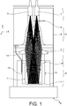
- FIG. 1 the preferred embodiment using a single beam and an absorption measurement.
- the optical source is typically a laser, for example a semiconductor diode.
- the optical beam delivered by the optical source is polarized by means of a rectilinear polarizer 8 interposed between the source and the cell 1 or directly integrated into the source.
- the beam passing through the cell is thus linearly polarized, which induces so-called "aligned" atomic states in cell 1, the alignment axis being fixed by the direction of the electric field of light used for pumping.
- aligned on the direction of linear polarization of the beam.
- the invention proposes to increase the effective length of interaction between the sensitive atomic gas located in the cell and the light of the optical beam which is used to measure its alignment state.
- the invention more particularly proposes to implement a multi-passage cavity which does not have the drawbacks of the cavity of Princeton University and which is suitable for pumping in linear polarization.
- the magnetometer comprises a collimator 2 arranged to collimate the light beam before it illuminates the cell and a mirror 3 arranged to reflect the collimated light beam after it has passed through the cell so that the collimated light beam makes a multi-pass through the cell by illuminating several times the same region of the cell.
- the beam of light which carries out these back and forth being collimated, that is to say that it presents neither convergence nor divergence of more than 5 °, it traverses a maximum of the volume of the cell with each passage.
- Its section is preferably substantially similar to that of the cell (for example for a tubular cell 1 cm in diameter, the beam section is at least 5 mm) which allows each passage to probe a significant portion of the atomic gas. and from there to achieve a significant gain in terms of signal-to-noise ratio.
- the mirror 3 can directly face the collimator.
- the mirror 3 can be directly arranged on a surface of the cell.
- the mirror 3 can for example be deposited on the surface of the cell in the form of a stack of thin dielectric layers or of a mixed stack dielectric / metal, which makes it possible to make the mirror and its positioning perfectly reproducible when the cell is also reproducible, for example because it is produced by molecular bonding processes.
- the mirror 3 is preferably a plane or quasi-plane mirror (by quasi-plane, it is understood that the radius of curvature of the mirror is at least 20 times, preferably at least 100 times, greater than the diameter of the mirror).
- a mirror is actually not very thick (its thickness is for example 0.5 mm) and the atomic gas which constitutes the sensitive element can then be located as close as possible to the external volume of a measurement compartment in which the cell is arranged. .
- This is particularly interesting for biological measurements, such as those carried out in magnetoencephalography where this mirror can be located almost in contact with the scalp of the patient so that the sensitive element is only a few millimeters from the source of the cortical signals. to measure.
- cell 1 can actually be arranged in a measurement compartment 5 of a magnetic field measurement probe 4.
- the probe 4 also comprises, stacked on the measurement compartment, an optical compartment 6 in which the collimator is arranged 2.
- the optical compartment 6 has in the plane ZX a section whose extension is similar to that of the measurement compartment 5 .
- the probe 4 thus has the shape of a right parallelepiped extending along the Y axis and has an upper face formed by an upper surface of the optical compartment 6 where an optical input 7 is located for the light beam and d a lower face formed by a lower surface of the measurement compartment 5 intended to be in contact with the source Sb of magnetic field to be measured.
- the optical beam delivered by the optical source is polarized by means of a rectilinear polarizer 8, the latter can be arranged in the optical compartment 6.
- the light beam can be brought from the optical source to the optical input 7 by means of an optical fiber.
- the upper surface of the optical compartment 6 can also have an optical output 9 for the light beam after its multi-passage through the cell.
- the collimator 2 can be used to focus the light beam towards the optical output, the latter being optically coupled to the detector, for example by means of an optical fiber.
- the optical output is merged with the optical input.
- the detector comprises a photodiode arranged in the optical compartment for photo-detecting the light beam after it has passed multiple times through the cell.
- the optical compartment 6 can also contain various elements intended to shape the beam of light and to reflect it towards the mirror 3 at the other end of the cell in the measurement compartment.
- These elements may include converging lenses and arrangements of reflective elements arranged in such a way that the light performs a fixed number of round trips in the cell.
- these elements may in particular comprise one or more auxiliary mirrors 10-13 on which the collimated light beam is incident and which are arranged in the optical compartment to participate in the multi-passage of the collimated light beam through the cell.
- the probe 4 can be arranged side by side with other similar probes, for example to form a matrix network making it possible to measure the magnetic field well resolved spatially. This arrangement can be carried out in a compact manner, without losing space to provide optical functions such as the routing of light, its polarization or its photo-detection.
- the object of each probe is to carry out a very low noise measurement of the magnetic field on the volume of its sensitive element, which makes it possible to ascend, by methods of reconstruction from field sources to the sources of currents located near the probes. These sources can be, for example, nervous currents in the brain, currents linked to cardiac functioning, or even currents originating from induction by a very low frequency magnetic source in a metal part to be characterized.
- the sensitive elements are located as close as possible to the field source, because the latter creates magnetic fields, the decrease of which varies in 1 / d 3 with the distance d from their source.
- the invention makes it possible to obtain a very dense assembly of the sensitive elements while maintaining a minimum distance between each of them and the field sources to be characterized.
- a probe beam is used, the linear polarization of which must ideally always remain in the same plane during its propagation (which is not the case in orientation where the plane of polarization of the light rotates under the effect of its interaction with atoms).
- the direction of propagation of the probe beam changes during the reflection or reflections undergone during the multi-passage, so that the direction of polarization, orthogonal to that of propagation, also risks changing.
- the multi-passage is carried out while preserving a direction of polarization of the invariant light beam.
- the inventors have indeed been able to observe, as much by theoretical modeling as by experimental measurements, that an optimal amplitude of the signal can be reached when the entire trajectories of light propagation through the cell are contained in one and the same plane, this plane, in this case the XY plane, being orthogonal to the linear polarization which therefore does not vary.
- the magnetometer also includes a high frequency discharge (HF) system, comprising an HF generator which supplies via wires 14 two HF discharge electrodes 15, to bring the atoms of the atomic gas in an energized state where they are capable of undergoing an atomic transition, typically in the metastable state 2 3 S 1 .
- HF high frequency discharge
- the mirror 3 of the measurement compartment or also where appropriate the mirror or mirrors of the optical compartment, are used as electrodes for igniting the discharge making it possible to populate the metastable state 2 3 S 1 .
- the mirror 3 of the measurement compartment or also where appropriate the mirror or mirrors of the optical compartment, are used as electrodes for igniting the discharge making it possible to populate the metastable state 2 3 S 1 .
- the magnetometer also comprises a circuit for excitation of parametric resonances which comprises a radiofrequency generator which supplies coils of Helmholtz of orthogonal axes which, carried by a support 16, surround the cell in order to generate a magnetic field of excitation of the parametric resonances, also designated by radiofrequency field of excitation.
- a radiofrequency generator which supplies coils of Helmholtz of orthogonal axes which, carried by a support 16, surround the cell in order to generate a magnetic field of excitation of the parametric resonances, also designated by radiofrequency field of excitation.
- Two excitation radiofrequency fields are typically applied to the cell and the directions of these fields, for example along the X and Y axes, determine the main directions of sensitivity of the magnetometer.
- the magnetometer can also include a closed loop servo system to constantly subject the cell to a zero total magnetic field.
- the servo system includes a regulator coupled to the processing electronics which injects a current into the Helmholtz coils which surround the cell 1 in order to generate a magnetic compensation field Bc such that the sum Bc + Bo is kept at zero by permanence.
- the magnetometer can be operated in an open loop, without compensation for the ambient field.
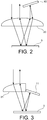
- the light beam is transported from the laser source where it is generated to each of the probes by an optical fiber. At the end of this fiber the beam diverges with an angle linked to the numerical aperture of the type of fiber used.
- a converging lens placed just below makes it possible to collimate this light and fix the diameter, for example at 6 mm.
- This collimated light passes through the sensitive element a first time then is reflected on a plane mirror, which reflects it so that it passes a second time through the same region of the sensitive element.
- this light again passes through the converging lens, which has the effect of making it converge inside a second optical fiber intended to convey it to '' to a photo-detector located outside the probe.
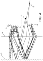
- FIG 4 represents in this respect a software modeling of a configuration example which, in addition to the collimator 2 and the mirror 3 of the measurement compartment, uses a second and a third mirrors 12, 13 arranged in the optical compartment to carry out eight passages through the cell from an entry point E to an exit point S.
Landscapes
- Physics & Mathematics (AREA)
- Engineering & Computer Science (AREA)
- Power Engineering (AREA)
- Condensed Matter Physics & Semiconductors (AREA)
- General Physics & Mathematics (AREA)
- Measurement And Recording Of Electrical Phenomena And Electrical Characteristics Of The Living Body (AREA)
- Measuring Magnetic Variables (AREA)
Applications Claiming Priority (1)
| Application Number | Priority Date | Filing Date | Title |
|---|---|---|---|
| FR1873864A FR3090890B1 (fr) | 2018-12-21 | 2018-12-21 | Magnétomètre à pompage optique d’un élément sensible avec une lumière polarisée linéairement et multi-passage dans l’élément sensible |
Publications (2)
| Publication Number | Publication Date |
|---|---|
| EP3671248A1 true EP3671248A1 (de) | 2020-06-24 |
| EP3671248B1 EP3671248B1 (de) | 2022-03-23 |
Family
ID=66676769
Family Applications (1)
| Application Number | Title | Priority Date | Filing Date |
|---|---|---|---|
| EP19218092.5A Active EP3671248B1 (de) | 2018-12-21 | 2019-12-19 | Magnetometer mit optischer pumpfunktion eines sensiblen elements mit einem linear polarisierten licht und mehrweg-durchgang in dem sensiblen element |
Country Status (3)
| Country | Link |
|---|---|
| US (1) | US11442119B2 (de) |
| EP (1) | EP3671248B1 (de) |
| FR (1) | FR3090890B1 (de) |
Families Citing this family (1)
| Publication number | Priority date | Publication date | Assignee | Title |
|---|---|---|---|---|
| US11953569B2 (en) * | 2020-11-05 | 2024-04-09 | The Trustees Of Princeton University | System and method for femtotesla direct magnetic gradiometer using a multipass cell |
Citations (3)
| Publication number | Priority date | Publication date | Assignee | Title |
|---|---|---|---|---|
| US20070205767A1 (en) * | 2005-11-28 | 2007-09-06 | The Regents Of The University Of California | Atomic magnetic gradiometer for room temperature high sensitivity magnetic field detection |
| US8212556B1 (en) * | 2010-01-12 | 2012-07-03 | Sandia Corporation | Atomic magnetometer |
| EP3364204A1 (de) * | 2017-02-15 | 2018-08-22 | Commissariat à l'énergie atomique et aux énergies alternatives | Mittles ac-stark-effekt kontrolliertes nullfeld-magnetometer |
Family Cites Families (19)
| Publication number | Priority date | Publication date | Assignee | Title |
|---|---|---|---|---|
| US6472869B1 (en) * | 2001-06-18 | 2002-10-29 | United States Of America As Represented By The Secretary Of The Air Force | Diode laser-pumped magnetometer |
| US8587304B2 (en) * | 2007-09-05 | 2013-11-19 | The Regents Of The University Of California | Optical atomic magnetometer |
| WO2009079054A2 (en) * | 2007-09-21 | 2009-06-25 | The Regents Of The University Of California | Radio frequency atomic magnetometer |
| JP5264242B2 (ja) * | 2008-03-26 | 2013-08-14 | キヤノン株式会社 | 原子磁力計及び磁力計測方法 |
| JP5446731B2 (ja) * | 2009-10-29 | 2014-03-19 | セイコーエプソン株式会社 | 磁場測定装置 |
| US8477825B2 (en) * | 2010-04-13 | 2013-07-02 | Coherent, Inc. | Polarization maintaining multi-pass imaging system for thin-disk amplifiers and oscillators |
| US8508844B2 (en) * | 2010-06-22 | 2013-08-13 | Coherent, Inc. | Hybrid fiber-MOPA |
| FR2984519B1 (fr) * | 2011-12-19 | 2014-02-21 | Commissariat Energie Atomique | Magnetometre a pompage optique integre et isotrope |
| US10712407B2 (en) * | 2013-02-07 | 2020-07-14 | Ben Gurion University Of The Negev Research And Development Authority | Device and methodology for measuring minute changes in ambient magnetic field |
| US8995052B1 (en) * | 2013-09-09 | 2015-03-31 | Coherent Kaiserslautern GmbH | Multi-stage MOPA with first-pulse suppression |
| US20150124318A1 (en) * | 2013-11-05 | 2015-05-07 | Electro-Optics Technology, Inc. | High magnetic field-type multi-pass faraday rotator |
| US9116201B2 (en) * | 2014-01-30 | 2015-08-25 | QuSpin Inc. | Method for detecting zero-field resonance |
| US9995800B1 (en) * | 2014-04-29 | 2018-06-12 | National Technology & Engineering Solutions Of Sandia, Llc | Atomic magnetometer with multiple spatial channels |
| FR3049702B1 (fr) | 2016-03-31 | 2018-04-13 | Commissariat A L'energie Atomique Et Aux Energies Alternatives | Dispositif de mesure de rotation, procede et centrale de navigation inertielle associes |
| FR3060114B1 (fr) | 2016-12-13 | 2019-05-17 | Commissariat A L'energie Atomique Et Aux Energies Alternatives | Procede d'aide a la navigation, produit programme d'ordinateur et centrale de navigation inertielle associes |
| FR3068461B1 (fr) | 2017-06-28 | 2019-08-30 | Commissariat A L'energie Atomique Et Aux Energies Alternatives | Procede de detection d'une rotation avec demarrage rapide d'un gyroscope atomique a pompage seop |
| FR3070817B1 (fr) | 2017-09-06 | 2019-09-13 | Commissariat A L'energie Atomique Et Aux Energies Alternatives | Systeme de mesure optique a asservissement davll stabilise |
| FR3077884B1 (fr) | 2018-02-12 | 2021-01-01 | Commissariat Energie Atomique | Magnetometre vectoriel a polarisation elliptique |
| FR3083876B1 (fr) | 2018-07-16 | 2020-10-16 | Commissariat Energie Atomique | Magnetometre vectoriel en alignement a deux faisceaux de sonde polarises differemment |
-
2018
- 2018-12-21 FR FR1873864A patent/FR3090890B1/fr not_active Expired - Fee Related
-
2019
- 2019-12-19 EP EP19218092.5A patent/EP3671248B1/de active Active
- 2019-12-20 US US16/723,096 patent/US11442119B2/en active Active
Patent Citations (3)
| Publication number | Priority date | Publication date | Assignee | Title |
|---|---|---|---|---|
| US20070205767A1 (en) * | 2005-11-28 | 2007-09-06 | The Regents Of The University Of California | Atomic magnetic gradiometer for room temperature high sensitivity magnetic field detection |
| US8212556B1 (en) * | 2010-01-12 | 2012-07-03 | Sandia Corporation | Atomic magnetometer |
| EP3364204A1 (de) * | 2017-02-15 | 2018-08-22 | Commissariat à l'énergie atomique et aux énergies alternatives | Mittles ac-stark-effekt kontrolliertes nullfeld-magnetometer |
Non-Patent Citations (2)
| Title |
|---|
| F. BEATO ET AL.: "Theory of a He parametric-resonance magnetometer based on atomic alignment", PHYSICAL REVIEW A, vol. 98, 2018, pages 053431, XP055607399, DOI: 10.1103/PhysRevA.98.053431 |
| S. LI ET AL.: "Optical rotation in excess of 100 rad generated by Rb vapor in a multipass cell", PHYS. REV. A, vol. 84, 2011, pages 061403, XP055165970, DOI: 10.1103/PhysRevA.84.061403 |
Also Published As
| Publication number | Publication date |
|---|---|
| FR3090890B1 (fr) | 2021-10-08 |
| EP3671248B1 (de) | 2022-03-23 |
| US20200200839A1 (en) | 2020-06-25 |
| US11442119B2 (en) | 2022-09-13 |
| FR3090890A1 (fr) | 2020-06-26 |
Similar Documents
| Publication | Publication Date | Title |
|---|---|---|
| FR3083876A1 (fr) | Magnetometre vectoriel en alignement a deux faisceaux de sonde polarises differemment | |
| EP0108671B1 (de) | Gerät zur Temperaturmessung und/oder elektrischen Intensitätsmessung mit dem Faraday-Effekt | |
| CA1283950C (fr) | Magnetometre a helium pompe par laser | |
| FR2663432A1 (fr) | Magnetometre a resonance et a pompage optique utilisant une pluralite de faisceaux multiplexes. | |
| EP0462002A1 (de) | Resonanzmagnetometer mit optischen Pumpen, das unterschiedliche Polarisationszustände verwendet | |
| EP3730959B1 (de) | Magnetometer gesteuert bei feldstärke null mit niedrigfrequenzfilterung des kompensationsfelds | |
| EP1075651A1 (de) | Verfahren zur anregung eines optischen resonators zum nachweis von gasspuren | |
| EP3907513B1 (de) | Stromsensor, der auf dem faraday-effekt in einem atomgas beruht | |
| EP3771917B1 (de) | Optisch gepumptes magnetometer | |
| EP3671248B1 (de) | Magnetometer mit optischer pumpfunktion eines sensiblen elements mit einem linear polarisierten licht und mehrweg-durchgang in dem sensiblen element | |
| EP0579537B1 (de) | Magnetometer mit polarisiertem Licht und gesteuertem Hochfrequenzfeld | |
| CA3074080A1 (fr) | Magnetometre scalaire isotrope et tout optique | |
| EP3650877A1 (de) | Kompaktes magnetometer mit hanle-effekt | |
| EP1674878B1 (de) | Elektrooptische Sonde zur Messung elektrischer oder elektromagnetischer Felder mit einer Steuerung der Wellenlänge des Betriebspunkts | |
| FR3088729A1 (fr) | Magnetometre en alignement a decalage angulaire entre polarisations des faisceaux de pompe et de sonde | |
| EP3961236B1 (de) | Elliptisch polarisiertes magnetometer mit zwei hochfrequenz-feldkomponenten zur detektion der parametrischen absorptionsresonanz | |
| WO2002095332A1 (fr) | Dispositif de mesure d'un effet non reciproque, notamment gyrometre a fibre optique | |
| FR3105825A1 (fr) | Dispositif de mesure optique d’un paramètre physique | |
| EP3919928A1 (de) | Dreiachsiges optisch gepumptes magnetometer für gradiometrische messungen | |
| WO1991007668A1 (fr) | Cellule de vapeurs atomiques ou moleculaires pour pompage optique et magnetometre ou gyroscope utilisant une telle cellule | |
| FR2656428A1 (fr) | Capteur de champ electrique a effet pockels. | |
| WO2001009661A1 (fr) | Dispositif permettant la determination de caracteristiques de la surface d'un objet. | |
| FR2806477A1 (fr) | Dispositif permettant la determination de caracteristiques de la surface d'un objet |
Legal Events
| Date | Code | Title | Description |
|---|---|---|---|
| PUAI | Public reference made under article 153(3) epc to a published international application that has entered the european phase |
Free format text: ORIGINAL CODE: 0009012 |
|
| STAA | Information on the status of an ep patent application or granted ep patent |
Free format text: STATUS: REQUEST FOR EXAMINATION WAS MADE |
|
| 17P | Request for examination filed |
Effective date: 20191219 |
|
| AK | Designated contracting states |
Kind code of ref document: A1 Designated state(s): AL AT BE BG CH CY CZ DE DK EE ES FI FR GB GR HR HU IE IS IT LI LT LU LV MC MK MT NL NO PL PT RO RS SE SI SK SM TR |
|
| AX | Request for extension of the european patent |
Extension state: BA ME |
|
| GRAP | Despatch of communication of intention to grant a patent |
Free format text: ORIGINAL CODE: EPIDOSNIGR1 |
|
| STAA | Information on the status of an ep patent application or granted ep patent |
Free format text: STATUS: GRANT OF PATENT IS INTENDED |
|
| INTG | Intention to grant announced |
Effective date: 20211029 |
|
| GRAS | Grant fee paid |
Free format text: ORIGINAL CODE: EPIDOSNIGR3 |
|
| GRAA | (expected) grant |
Free format text: ORIGINAL CODE: 0009210 |
|
| STAA | Information on the status of an ep patent application or granted ep patent |
Free format text: STATUS: THE PATENT HAS BEEN GRANTED |
|
| AK | Designated contracting states |
Kind code of ref document: B1 Designated state(s): AL AT BE BG CH CY CZ DE DK EE ES FI FR GB GR HR HU IE IS IT LI LT LU LV MC MK MT NL NO PL PT RO RS SE SI SK SM TR |
|
| REG | Reference to a national code |
Ref country code: GB Ref legal event code: FG4D Free format text: NOT ENGLISH |
|
| REG | Reference to a national code |
Ref country code: CH Ref legal event code: EP |
|
| REG | Reference to a national code |
Ref country code: IE Ref legal event code: FG4D Free format text: LANGUAGE OF EP DOCUMENT: FRENCH |
|
| REG | Reference to a national code |
Ref country code: DE Ref legal event code: R096 Ref document number: 602019012796 Country of ref document: DE |
|
| REG | Reference to a national code |
Ref country code: AT Ref legal event code: REF Ref document number: 1477807 Country of ref document: AT Kind code of ref document: T Effective date: 20220415 |
|
| REG | Reference to a national code |
Ref country code: LT Ref legal event code: MG9D |
|
| REG | Reference to a national code |
Ref country code: NL Ref legal event code: MP Effective date: 20220323 |
|
| PG25 | Lapsed in a contracting state [announced via postgrant information from national office to epo] |
Ref country code: SE Free format text: LAPSE BECAUSE OF FAILURE TO SUBMIT A TRANSLATION OF THE DESCRIPTION OR TO PAY THE FEE WITHIN THE PRESCRIBED TIME-LIMIT Effective date: 20220323 Ref country code: RS Free format text: LAPSE BECAUSE OF FAILURE TO SUBMIT A TRANSLATION OF THE DESCRIPTION OR TO PAY THE FEE WITHIN THE PRESCRIBED TIME-LIMIT Effective date: 20220323 Ref country code: NO Free format text: LAPSE BECAUSE OF FAILURE TO SUBMIT A TRANSLATION OF THE DESCRIPTION OR TO PAY THE FEE WITHIN THE PRESCRIBED TIME-LIMIT Effective date: 20220623 Ref country code: LT Free format text: LAPSE BECAUSE OF FAILURE TO SUBMIT A TRANSLATION OF THE DESCRIPTION OR TO PAY THE FEE WITHIN THE PRESCRIBED TIME-LIMIT Effective date: 20220323 Ref country code: HR Free format text: LAPSE BECAUSE OF FAILURE TO SUBMIT A TRANSLATION OF THE DESCRIPTION OR TO PAY THE FEE WITHIN THE PRESCRIBED TIME-LIMIT Effective date: 20220323 Ref country code: BG Free format text: LAPSE BECAUSE OF FAILURE TO SUBMIT A TRANSLATION OF THE DESCRIPTION OR TO PAY THE FEE WITHIN THE PRESCRIBED TIME-LIMIT Effective date: 20220623 |
|
| REG | Reference to a national code |
Ref country code: AT Ref legal event code: MK05 Ref document number: 1477807 Country of ref document: AT Kind code of ref document: T Effective date: 20220323 |
|
| PG25 | Lapsed in a contracting state [announced via postgrant information from national office to epo] |
Ref country code: LV Free format text: LAPSE BECAUSE OF FAILURE TO SUBMIT A TRANSLATION OF THE DESCRIPTION OR TO PAY THE FEE WITHIN THE PRESCRIBED TIME-LIMIT Effective date: 20220323 Ref country code: GR Free format text: LAPSE BECAUSE OF FAILURE TO SUBMIT A TRANSLATION OF THE DESCRIPTION OR TO PAY THE FEE WITHIN THE PRESCRIBED TIME-LIMIT Effective date: 20220624 Ref country code: FI Free format text: LAPSE BECAUSE OF FAILURE TO SUBMIT A TRANSLATION OF THE DESCRIPTION OR TO PAY THE FEE WITHIN THE PRESCRIBED TIME-LIMIT Effective date: 20220323 |
|
| PG25 | Lapsed in a contracting state [announced via postgrant information from national office to epo] |
Ref country code: NL Free format text: LAPSE BECAUSE OF FAILURE TO SUBMIT A TRANSLATION OF THE DESCRIPTION OR TO PAY THE FEE WITHIN THE PRESCRIBED TIME-LIMIT Effective date: 20220323 |
|
| PG25 | Lapsed in a contracting state [announced via postgrant information from national office to epo] |
Ref country code: SM Free format text: LAPSE BECAUSE OF FAILURE TO SUBMIT A TRANSLATION OF THE DESCRIPTION OR TO PAY THE FEE WITHIN THE PRESCRIBED TIME-LIMIT Effective date: 20220323 Ref country code: SK Free format text: LAPSE BECAUSE OF FAILURE TO SUBMIT A TRANSLATION OF THE DESCRIPTION OR TO PAY THE FEE WITHIN THE PRESCRIBED TIME-LIMIT Effective date: 20220323 Ref country code: RO Free format text: LAPSE BECAUSE OF FAILURE TO SUBMIT A TRANSLATION OF THE DESCRIPTION OR TO PAY THE FEE WITHIN THE PRESCRIBED TIME-LIMIT Effective date: 20220323 Ref country code: PT Free format text: LAPSE BECAUSE OF FAILURE TO SUBMIT A TRANSLATION OF THE DESCRIPTION OR TO PAY THE FEE WITHIN THE PRESCRIBED TIME-LIMIT Effective date: 20220725 Ref country code: ES Free format text: LAPSE BECAUSE OF FAILURE TO SUBMIT A TRANSLATION OF THE DESCRIPTION OR TO PAY THE FEE WITHIN THE PRESCRIBED TIME-LIMIT Effective date: 20220323 Ref country code: EE Free format text: LAPSE BECAUSE OF FAILURE TO SUBMIT A TRANSLATION OF THE DESCRIPTION OR TO PAY THE FEE WITHIN THE PRESCRIBED TIME-LIMIT Effective date: 20220323 Ref country code: CZ Free format text: LAPSE BECAUSE OF FAILURE TO SUBMIT A TRANSLATION OF THE DESCRIPTION OR TO PAY THE FEE WITHIN THE PRESCRIBED TIME-LIMIT Effective date: 20220323 Ref country code: AT Free format text: LAPSE BECAUSE OF FAILURE TO SUBMIT A TRANSLATION OF THE DESCRIPTION OR TO PAY THE FEE WITHIN THE PRESCRIBED TIME-LIMIT Effective date: 20220323 |
|
| PG25 | Lapsed in a contracting state [announced via postgrant information from national office to epo] |
Ref country code: PL Free format text: LAPSE BECAUSE OF FAILURE TO SUBMIT A TRANSLATION OF THE DESCRIPTION OR TO PAY THE FEE WITHIN THE PRESCRIBED TIME-LIMIT Effective date: 20220323 Ref country code: IS Free format text: LAPSE BECAUSE OF FAILURE TO SUBMIT A TRANSLATION OF THE DESCRIPTION OR TO PAY THE FEE WITHIN THE PRESCRIBED TIME-LIMIT Effective date: 20220723 Ref country code: AL Free format text: LAPSE BECAUSE OF FAILURE TO SUBMIT A TRANSLATION OF THE DESCRIPTION OR TO PAY THE FEE WITHIN THE PRESCRIBED TIME-LIMIT Effective date: 20220323 |
|
| REG | Reference to a national code |
Ref country code: DE Ref legal event code: R097 Ref document number: 602019012796 Country of ref document: DE |
|
| PLBE | No opposition filed within time limit |
Free format text: ORIGINAL CODE: 0009261 |
|
| STAA | Information on the status of an ep patent application or granted ep patent |
Free format text: STATUS: NO OPPOSITION FILED WITHIN TIME LIMIT |
|
| PG25 | Lapsed in a contracting state [announced via postgrant information from national office to epo] |
Ref country code: DK Free format text: LAPSE BECAUSE OF FAILURE TO SUBMIT A TRANSLATION OF THE DESCRIPTION OR TO PAY THE FEE WITHIN THE PRESCRIBED TIME-LIMIT Effective date: 20220323 |
|
| 26N | No opposition filed |
Effective date: 20230102 |
|
| PG25 | Lapsed in a contracting state [announced via postgrant information from national office to epo] |
Ref country code: SI Free format text: LAPSE BECAUSE OF FAILURE TO SUBMIT A TRANSLATION OF THE DESCRIPTION OR TO PAY THE FEE WITHIN THE PRESCRIBED TIME-LIMIT Effective date: 20220323 |
|
| PG25 | Lapsed in a contracting state [announced via postgrant information from national office to epo] |
Ref country code: IT Free format text: LAPSE BECAUSE OF FAILURE TO SUBMIT A TRANSLATION OF THE DESCRIPTION OR TO PAY THE FEE WITHIN THE PRESCRIBED TIME-LIMIT Effective date: 20220323 |
|
| REG | Reference to a national code |
Ref country code: CH Ref legal event code: PL |
|
| REG | Reference to a national code |
Ref country code: BE Ref legal event code: MM Effective date: 20221231 |
|
| PG25 | Lapsed in a contracting state [announced via postgrant information from national office to epo] |
Ref country code: LU Free format text: LAPSE BECAUSE OF NON-PAYMENT OF DUE FEES Effective date: 20221219 |
|
| PG25 | Lapsed in a contracting state [announced via postgrant information from national office to epo] |
Ref country code: LI Free format text: LAPSE BECAUSE OF NON-PAYMENT OF DUE FEES Effective date: 20221231 Ref country code: IE Free format text: LAPSE BECAUSE OF NON-PAYMENT OF DUE FEES Effective date: 20221219 Ref country code: CH Free format text: LAPSE BECAUSE OF NON-PAYMENT OF DUE FEES Effective date: 20221231 |
|
| PG25 | Lapsed in a contracting state [announced via postgrant information from national office to epo] |
Ref country code: BE Free format text: LAPSE BECAUSE OF NON-PAYMENT OF DUE FEES Effective date: 20221231 |
|
| PG25 | Lapsed in a contracting state [announced via postgrant information from national office to epo] |
Ref country code: HU Free format text: LAPSE BECAUSE OF FAILURE TO SUBMIT A TRANSLATION OF THE DESCRIPTION OR TO PAY THE FEE WITHIN THE PRESCRIBED TIME-LIMIT; INVALID AB INITIO Effective date: 20191219 |
|
| PG25 | Lapsed in a contracting state [announced via postgrant information from national office to epo] |
Ref country code: CY Free format text: LAPSE BECAUSE OF FAILURE TO SUBMIT A TRANSLATION OF THE DESCRIPTION OR TO PAY THE FEE WITHIN THE PRESCRIBED TIME-LIMIT Effective date: 20220323 |
|
| PG25 | Lapsed in a contracting state [announced via postgrant information from national office to epo] |
Ref country code: MK Free format text: LAPSE BECAUSE OF FAILURE TO SUBMIT A TRANSLATION OF THE DESCRIPTION OR TO PAY THE FEE WITHIN THE PRESCRIBED TIME-LIMIT Effective date: 20220323 |
|
| PG25 | Lapsed in a contracting state [announced via postgrant information from national office to epo] |
Ref country code: MC Free format text: LAPSE BECAUSE OF FAILURE TO SUBMIT A TRANSLATION OF THE DESCRIPTION OR TO PAY THE FEE WITHIN THE PRESCRIBED TIME-LIMIT Effective date: 20220323 |
|
| PG25 | Lapsed in a contracting state [announced via postgrant information from national office to epo] |
Ref country code: TR Free format text: LAPSE BECAUSE OF FAILURE TO SUBMIT A TRANSLATION OF THE DESCRIPTION OR TO PAY THE FEE WITHIN THE PRESCRIBED TIME-LIMIT Effective date: 20220323 Ref country code: MC Free format text: LAPSE BECAUSE OF FAILURE TO SUBMIT A TRANSLATION OF THE DESCRIPTION OR TO PAY THE FEE WITHIN THE PRESCRIBED TIME-LIMIT Effective date: 20220323 |
|
| PG25 | Lapsed in a contracting state [announced via postgrant information from national office to epo] |
Ref country code: MT Free format text: LAPSE BECAUSE OF FAILURE TO SUBMIT A TRANSLATION OF THE DESCRIPTION OR TO PAY THE FEE WITHIN THE PRESCRIBED TIME-LIMIT Effective date: 20220323 |
|
| PGFP | Annual fee paid to national office [announced via postgrant information from national office to epo] |
Ref country code: DE Payment date: 20241219 Year of fee payment: 6 |
|
| PGFP | Annual fee paid to national office [announced via postgrant information from national office to epo] |
Ref country code: GB Payment date: 20251229 Year of fee payment: 7 |
|
| PGFP | Annual fee paid to national office [announced via postgrant information from national office to epo] |
Ref country code: FR Payment date: 20251222 Year of fee payment: 7 |