EP3671262A1 - Procédé et système de gestion de secteurs aveugles de couches de balayage de capteurs redondants dans un véhicule - Google Patents
Procédé et système de gestion de secteurs aveugles de couches de balayage de capteurs redondants dans un véhicule Download PDFInfo
- Publication number
- EP3671262A1 EP3671262A1 EP18315052.3A EP18315052A EP3671262A1 EP 3671262 A1 EP3671262 A1 EP 3671262A1 EP 18315052 A EP18315052 A EP 18315052A EP 3671262 A1 EP3671262 A1 EP 3671262A1
- Authority
- EP
- European Patent Office
- Prior art keywords
- vehicle
- redundant
- sensors
- redundant sensors
- scanning
- Prior art date
- Legal status (The legal status is an assumption and is not a legal conclusion. Google has not performed a legal analysis and makes no representation as to the accuracy of the status listed.)
- Granted
Links
Images


Classifications
-
- G—PHYSICS
- G01—MEASURING; TESTING
- G01S—RADIO DIRECTION-FINDING; RADIO NAVIGATION; DETERMINING DISTANCE OR VELOCITY BY USE OF RADIO WAVES; LOCATING OR PRESENCE-DETECTING BY USE OF THE REFLECTION OR RERADIATION OF RADIO WAVES; ANALOGOUS ARRANGEMENTS USING OTHER WAVES
- G01S17/00—Systems using the reflection or reradiation of electromagnetic waves other than radio waves, e.g. lidar systems
- G01S17/88—Lidar systems specially adapted for specific applications
- G01S17/93—Lidar systems specially adapted for specific applications for anti-collision purposes
- G01S17/931—Lidar systems specially adapted for specific applications for anti-collision purposes of land vehicles
-
- B—PERFORMING OPERATIONS; TRANSPORTING
- B60—VEHICLES IN GENERAL
- B60W—CONJOINT CONTROL OF VEHICLE SUB-UNITS OF DIFFERENT TYPE OR DIFFERENT FUNCTION; CONTROL SYSTEMS SPECIALLY ADAPTED FOR HYBRID VEHICLES; ROAD VEHICLE DRIVE CONTROL SYSTEMS FOR PURPOSES NOT RELATED TO THE CONTROL OF A PARTICULAR SUB-UNIT
- B60W50/00—Details of control systems for road vehicle drive control not related to the control of a particular sub-unit, e.g. process diagnostic or vehicle driver interfaces
- B60W50/08—Interaction between the driver and the control system
- B60W50/14—Means for informing the driver, warning the driver or prompting a driver intervention
-
- G—PHYSICS
- G01—MEASURING; TESTING
- G01S—RADIO DIRECTION-FINDING; RADIO NAVIGATION; DETERMINING DISTANCE OR VELOCITY BY USE OF RADIO WAVES; LOCATING OR PRESENCE-DETECTING BY USE OF THE REFLECTION OR RERADIATION OF RADIO WAVES; ANALOGOUS ARRANGEMENTS USING OTHER WAVES
- G01S17/00—Systems using the reflection or reradiation of electromagnetic waves other than radio waves, e.g. lidar systems
- G01S17/02—Systems using the reflection of electromagnetic waves other than radio waves
- G01S17/06—Systems determining position data of a target
- G01S17/42—Simultaneous measurement of distance and other co-ordinates
-
- G—PHYSICS
- G01—MEASURING; TESTING
- G01S—RADIO DIRECTION-FINDING; RADIO NAVIGATION; DETERMINING DISTANCE OR VELOCITY BY USE OF RADIO WAVES; LOCATING OR PRESENCE-DETECTING BY USE OF THE REFLECTION OR RERADIATION OF RADIO WAVES; ANALOGOUS ARRANGEMENTS USING OTHER WAVES
- G01S17/00—Systems using the reflection or reradiation of electromagnetic waves other than radio waves, e.g. lidar systems
- G01S17/87—Combinations of systems using electromagnetic waves other than radio waves
-
- G—PHYSICS
- G01—MEASURING; TESTING
- G01S—RADIO DIRECTION-FINDING; RADIO NAVIGATION; DETERMINING DISTANCE OR VELOCITY BY USE OF RADIO WAVES; LOCATING OR PRESENCE-DETECTING BY USE OF THE REFLECTION OR RERADIATION OF RADIO WAVES; ANALOGOUS ARRANGEMENTS USING OTHER WAVES
- G01S7/00—Details of systems according to groups G01S13/00, G01S15/00, G01S17/00
- G01S7/48—Details of systems according to groups G01S13/00, G01S15/00, G01S17/00 of systems according to group G01S17/00
- G01S7/481—Constructional features, e.g. arrangements of optical elements
- G01S7/4814—Constructional features, e.g. arrangements of optical elements of transmitters alone
- G01S7/4815—Constructional features, e.g. arrangements of optical elements of transmitters alone using multiple transmitters
-
- G—PHYSICS
- G01—MEASURING; TESTING
- G01S—RADIO DIRECTION-FINDING; RADIO NAVIGATION; DETERMINING DISTANCE OR VELOCITY BY USE OF RADIO WAVES; LOCATING OR PRESENCE-DETECTING BY USE OF THE REFLECTION OR RERADIATION OF RADIO WAVES; ANALOGOUS ARRANGEMENTS USING OTHER WAVES
- G01S7/00—Details of systems according to groups G01S13/00, G01S15/00, G01S17/00
- G01S7/48—Details of systems according to groups G01S13/00, G01S15/00, G01S17/00 of systems according to group G01S17/00
- G01S7/481—Constructional features, e.g. arrangements of optical elements
- G01S7/4817—Constructional features, e.g. arrangements of optical elements relating to scanning
-
- G—PHYSICS
- G01—MEASURING; TESTING
- G01S—RADIO DIRECTION-FINDING; RADIO NAVIGATION; DETERMINING DISTANCE OR VELOCITY BY USE OF RADIO WAVES; LOCATING OR PRESENCE-DETECTING BY USE OF THE REFLECTION OR RERADIATION OF RADIO WAVES; ANALOGOUS ARRANGEMENTS USING OTHER WAVES
- G01S7/00—Details of systems according to groups G01S13/00, G01S15/00, G01S17/00
- G01S7/48—Details of systems according to groups G01S13/00, G01S15/00, G01S17/00 of systems according to group G01S17/00
- G01S7/497—Means for monitoring or calibrating
- G01S2007/4975—Means for monitoring or calibrating of sensor obstruction by, e.g. dirt- or ice-coating, e.g. by reflection measurement on front-screen
Definitions
- the present technology relates to handling obstructive elements affecting redundant sensors mounted on a vehicle to assist with its navigation.
- Sensor » designates an opto-electronic apparatus, such as a LIDAR sensor, based on the principle of emitting a lightwave beam, catching the reflections of objects in the field of view, and providing distance information about reflecting objects, with a given scanning frequency in one or multiple scanning layers.
- Sensors are susceptible to obstructive elements such as dirt, dead bugs, droppings, soap residues or water spots, or even cracks in the protective housing for the opto-electronic, with such protective housing being an integral part of the sensors, or being added around and about them by protective elements of the vehicle (glass or other material that is transparent to the optical beam used by the sensor).
- obstructive elements disrupt the accuracy of the sensors by effectively creating blind sectors in the scanning layer(s), and putting navigation of the vehicle at risk.
- Systems have been devised to help increasing availability of reliable data from sensors by checking the conditions of their protective housing, and/or cleaning it as the case may be, and keeping sensors free of obstructive elements as long and as often as possible. However, there remains periods of time when this is not the case.
- Monitored zone designates a zone extending from the vehicle, designed to detect every obstacle onto and close to the vehicle trajectory that is creating a risk of collision.
- the maximum size of the monitored zone is such that the monitored zone is contained entirely in the region of overlap between scanning layers.
- the actual size within that limit may be either fixed, or dynamically calculated as a function of the speed, steering and mechanical characteristics of the vehicle (shape of the vehicle, maximal deceleration, brake reaction time) or latencies of the software onboard the vehicle (for example software that is controlling an autonomous or driverless vehicle), or a combination of one or more of these parameters. For example when the vehicle is stopped, the monitored zone has no surface.
- Various implementations of the present technology provide a method of handling blind sectors in scanning layers of at least two, a first and a second, redundant sensors being mounted on a vehicle from which a monitored zone extends, such redundant sensors each providing a cloud of points representative of objects present in their respective fields of view, the method comprising the steps of:
- the method further includes the steps of:
- the method further includes the steps of, upon receiving the critical signal, stopping the vehicle in emergency.
- the method further includes the steps of, upon receiving the critical signal, changing the speed and/or steering of the vehicle so as to remove the overlap from the monitored zone.
- the method further includes the steps of, upon receiving the critical signal, sending a signal to a driver of the vehicle requiring immediate attention.
- the method further includes the steps of, upon detecting for any one of the redundant sensors that the density of abnormal cloud points exceeds the first threshold, and the size of the cloud of abnormal cloud points does not exceed the second threshold, sending a warning signal to the vehicle about the one sensor.
- the method further includes the steps of, upon detecting for any one of the redundant sensors that the density of abnormal cloud points exceeds the first threshold, and the size of the cloud of abnormal cloud points exceeds the second threshold, sending an alarm signal to the vehicle about the one sensor.
- the method further includes the steps of, if scanning layers of the first and second redundant sensors are not in the same plane, or are not parallel, orthogonally projecting scanning layers on a substantially horizontal plane within the vehicle's reference system.
- the method further includes the steps of, if n redundant sensors are mounted on the vehicle, with n being equal or superior to 3, calculating the overlap simultaneously for all n redundant sensors.
- the first threshold and/or the second threshold are adapted to each one of the redundant sensors.
- Various implementations of the present technology also provide a system of handling blind sectors in scanning layers of redundant sensors in a vehicle, comprising:
- the safety critical system is further configured to:
- system further comprises a vehicle traction and steering actuators and sensors system configured to, upon receiving the critical signal, stopping the vehicle in emergency.
- system further comprises a vehicle traction and steering actuators and sensors system configured to, upon receiving the critical signal, changing the speed and/or steering of the vehicle so as to remove the overlap from the monitored zone.
- the safety critical system is further configured to:
- the safety critical system is further configured to:
- the safety critical system is further configured to, when scanning layers of the first and second redundant sensors are not in the same plane, or are not parallel, orthogonally project scanning layers on a substantially horizontal plane within the vehicle's reference system, prior to calculating an overlap between each detected large blind sector in any scanning layer of the first redundant sensor and each detected large blind sector in any scanning layer of the second redundant sensor.
- n redundant sensors are mounted on the vehicle, with n being equal or superior to 3, and the safety critical system is further configured to calculate the overlap simultaneously for all n redundant sensors.
- the safety critical system is further configured to adapt the first threshold and/or the second threshold to each one of the redundant sensors.
- system further comprises a navigation system configured to:
- the safety critical system is further configured to calculate the monitored zone extending from the vehicle.
- Implementations of the present technology each have at least one of the above mentioned object and/or aspects, but do not necessarily have all of them.
- the functions of the various elements shown in the figures, including any functional block, may be provided through the use of dedicated hardware as well as hardware capable of executing software in association with appropriate software.
- the functions may be provided by a single dedicated processor, by a single shared processor, or by a plurality of individual processors, some of which may be shared.
- the processor may be a general purpose processor, such as a central processing unit (CPU) or a processor dedicated to a specific purpose, such as a digital signal processor (DSP).
- CPU central processing unit
- DSP digital signal processor
- processor » should not be construed to refer exclusively to hardware capable of executing software, and may implicitly include, without limitation, application specific integrated circuit (ASIC), field programmable gate array (FPGA), read-only memory (ROM) for storing software, random access memory (RAM), and non-volatile storage.
- ASIC application specific integrated circuit
- FPGA field programmable gate array
- ROM read-only memory
- RAM random access memory
- non-volatile storage Other hardware, conventional and/or custom, may also be included.
- Modules may be represented herein as any combination of flowchart elements or other elements indicating performance of process steps and/or textual description. Such modules may be executed by hardware that is expressly or implicitly shown. Moreover, it should be understood that « module » may include for example, but without being limitative, computer program logic, computer program instructions, software, stack, firmware, hardware circuitry or a combination thereof which provides the required capabilities.
- Fig.1 is a top view of a vehicle equipped with two redundant sensors in a substantially straight line trajectory.
- Vehicle 1 moves in the direction of the arrow. It is equipped with two redundant sensors 2 and 3 having respective scanning layers 5 and 6 toward the front of vehicle 1.
- a monitored zone 4 is defined around the vehicle 1, either fixed or adapted in shape and size based on speed, steering and mechanical characteristics of the vehicle 1 (shape of the vehicle, maximal deceleration, brake reaction time%) as well as latencies of software onboard vehicle 1.
- Sensors 2 and 3 are redundant in that their scanning layers 5 and 6 overlap in a region 7.
- a blind sector in either redundant sensor 2 or 3 may be represented as a slice in the top view of either scanning layer 5 or 6, where failure of the protective housing or the redundant sensor itself prevents the lightwave beam from going through and creating a gap in the horizontal field of view.
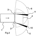
- Fig.2 illustrates the case of non overlapping blind sectors between two redundant sensors.
- Each of redundant sensors 2 and 3 has a gap in its horizontal field of view, respectively blind sectors 10 and 11.
- the two blind sectors do not overlap.
- redundancy allows to send a warning or alarm signal, depending on the opening of the angle of blind sectors 10 and 11, that the redundant sensors need to be cleaned, but the vehicle 1 can continue operating safely.
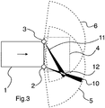
- Fig.3 illustrates the case of blind sectors overlapping outside of the monitored zone.
- Blind sectors 10 and 11 overlap in a region 12 that is located outside of monitored zone 4.
- the overlap is not instantly critical in the sense that the monitored zone is not currently affected, but it could become critical if and when the monitored zone 4 changes based on speed, steering and mechanical characteristics of the vehicle 1 (shape of the vehicle, maximal deceleration, brake reaction time%) as well as latencies of software onboard vehicle 1.
- an alarm signal is sent to have to clean redundant sensors 2 and 3.
- the alarm signal could for example be sent to a remote operator of vehicle 1, in the case of an autonomous or driverless vehicle, or to the owner of vehicle 1, or to a facility in charge of maintenance of vehicle 1.
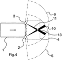
- Fig.4 illustrates the case of blind sectors overlapping within the monitored zone.
- Blind sectors 10 and 11 overlap in a region 13 that is located within the monitored zone 4.
- the overlap is critical in the sense that the monitored zone is affected and safety potentially compromised, as an obstacle might be hidden by the overlap of the two blind sectors 10 and 11.
- a critical signal is sent to the vehicle 1.
- action may be taken by the software onboard vehicle 1.
- an emergency stop of the vehicle 1 may be triggered, or a change in its speed and/or steering may be triggered having as a result that the overlap between blind sectors 10 and 11 is kept outside of the monitored zone 4.
- a critical signal may be sent to the driver of vehicle 1, and/or cruise or auto control may be turned off, requiring immediate attention on the part of the driver.
- Redundant sensors 2 and 3 each typically provides a cloud of points, with each point coming with 3D coordinates (such as X,Y and Z (Cartesian) or Rho, Theta and Phi (Spherical)) information within the sensor's reference system, representing essentially the distance (Rho) between the lightwave beam source and the object that reflected the beam, a horizontal angle (Theta) and a scanning layer angle (Phi) in the case of sensors with multiple scanning layers.
- 3D coordinates such as X,Y and Z (Cartesian) or Rho, Theta and Phi (Spherical)
- Points with a distance (Rho) that is about, or in the same order of magnitude as, the distance between the lightwave beam source and the outer surface of the sensors' protective housing are suspected to be indicative of the presence of obstructive elements that are in the vicinity of the redundant sensor's protective housing, and thus degrade the perception performances of the sensors, leading potentially to blind sector(s). Such points are called « abnormal points » hereafter.
- the distance between the lightwave beam source and the outer surface of the sensors' protective housing depends on the type of sensor and its characteristics, and as the case may be, on the protective elements of the vehicle around the sensor. Such a distance may for example be between 5 and 500mm.
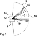
- Fig.5 illustrates an example of blind sector on one redundant sensor.
- the blind sector 10 is a slice in redundant sensor 2's horizontal field of view (or a orthogonal projection of the field of view on a substantially horizontal plane within the vehicle's reference system) with an angle 51 and a vertex 50 at, or about at, the lightwave beam source.
- Redundant sensor 2 emits successive lightwave beams 53 (a fraction of them only is represented) separated by small angles, for example 0.25 degree, to form the scanning layer 5, and provides a cloud of points as a measure of the length till each lightwave beam is being reflected by an object in the field of view.
- Abnormal points 54 are caused by the presence of obstructive elements in the vicinity of the protective housing of redundant sensor 2, shown here as including protective elements 52 of the vehicle 1.
- the lightwave beams are reflected back at a distance which is about, or in the same order of magnitude as, the distance between the vertex 50 and the outer limits of the protective elements 52. If these abnormal points have a concentration or density that exceeds a first threshold, then a blind sector is detected.
- the first threshold for the concentration or density of abnormal points is empirically determined based on a number of factors, including any or all of, without limitation: characteristics of the sensor such as wavelength, technology, resolution, etc., trade off between the level of safety and utilisation time of vehicle 1, the position of redundant sensors 2 and 3 on the vehicle 1 in particular relative to the road which is a source of obstructive elements such as water or dirt, the particular environment which vehicle 1 is routinely going to encounter, etc.
- a blind sector may be considered formed with a first threshold having a value of between 1 and 2 points/degree.
- a warning signal may be sent to have to clean redundant sensor 2.
- the warning signal could for example be sent to a remote operator of vehicle 1, in the case of an autonomous or driverless vehicle, or to the owner of vehicle 1, or to a facility in charge of maintenance of vehicle 1.
- the size of the angle 51 is determined by the size of the cloud of abnormal points. If the angle 51 is larger than a second threshold, then a « large blind sector » is considered to be formed.
- the second threshold is empirically determined based on a number of factors, including any or all of, without limitation: trade off between the level of safety and utilisation time of vehicle 1, the position of redundant sensors 2 and 3 on the vehicle 1 in particular relative to the road, the particular environment which vehicle 1 is routinely going to encounter, etc.
- a large blind sector may be considered formed with a second threshold having a value of between 2 and 8 degrees.
- an alarm signal dedicated to redundant sensor 2 may be sent to have to clean redundant sensor 2.
- the alarm signal could for example be sent to a remote operator of vehicle 1, in the case of an autonomous or driverless vehicle, or to the owner of vehicle 1, or to a facility in charge of maintenance of vehicle 1. In this case, any overlapping region between large blind sector 10 and any large blind sector(s) of redundant sensor 3 is monitored.
- the first threshold and the second threshold for the angle 51 in redundant sensor 2 may be identical to, or different from, the first threshold and the second threshold used for the angle of blind sector(s) of redundant sensor 3.
- the first and second thresholds for redundant sensor 2 may respectively be 1.25 and 4 degrees, while the first and second thresholds for redundant sensor 3 may be 1 and 6 degrees.
- Any overlapping region between large blind sectors of redundant sensors is the geometrical intersection between the large blind sectors, ie the set of points that belong to all of these large blind sectors.
- a critical signal may be sent, resulting in emergency change in speed and/or steering, in the case of an autonomous or driverless vehicle, or immediate attention requested on the part of the driver.
- Fig.7 is a block diagram showing the configuration in an embodiment of the invention for an autonomous or driverless vehicle.
- Vehicle 1 is represented in a top view, equipped with two redundant sensors 2 and 3 having respective scanning layers 5 and 6.
- Redundant sensors 2 and 3 provide scanning information, including cloud of points information, respectively through data links 75 and 74, to a navigation system 70, and a safety critical system 72.
- the navigation system 70 exploits data received from redundant sensors 2 and 3 to make decisions regarding navigation of vehicle 1. Based on such decisions, navigation system 70 sends commands to, and receives feedback from, vehicle traction and steering actuators and sensors system 71, through data link 77.
- the safety critical system 72 exploits data received from redundant sensors 2 and 3 to make decisions regarding navigation of vehicle 1 as they relate to blind sectors detected in the scanning layers 5 and 6 according to the invention. Based on such decisions, safety critical system 72 sends commands to, and receives feedback from, vehicle traction and steering actuators and sensors system 71, through data link 78. Any decision made by the safety critical system 72 is communicated to navigation system 70 through data link 76. Through data links 76 and 78, the decisions of safety critical system 72, as they relate to safety, prevail over those of navigation system 70, and the commands of safety critical system 72 to vehicle traction and steering actuators and sensors system 71 override those of navigation system 70.
- safety critical system 72 One of the functions performed by the safety critical system 72 is that of calculation of the monitored zone 4 extending from vehicle 1.
- navigation system 70 may calculate the monitored zone 4, and feed that information to safety critical system 72, for example through data link 76 (not shown).
- safety critical system 72 makes the decision as to whether any overlap between any large blind sector of the scanning layer 5 of redundant sensor 2 and any large blind sector of the scanning layer 6 of redundant sensor 3, lies within the monitored zone 4.
- navigation and state of vehicle 1 may be communicated to a remote supervision system 73 through a data link 7, which may take the form of an over-the-air data channel.
- Remote supervision system 73 can thus be informed including of decisions made by safety critical system 72, commands sent to vehicle traction and steering actuators and sensors system 71 as the case may be, and signals (warning, alarm, critical) if any sent by safety critical system 72.
- navigation system 70 and supervision system 73 may perform differently, and that, although safety critical system 72 may make decisions and send signals according to the invention, in substantially the same manner as in the case of an autonomous or driverless vehicle, it may not have the same command control over vehicle traction and steering actuators and sensors system 71.
- blocks represent functions which may be realized in single physical entities.
- Each block may comprise hardware and/or software and/or firmware (or a combination thereof), as is known in the art, to execute functions according to the invention, including the process described in relation to Fig.6 .
- Fig.6 is a flowchart illustrating a decision process according to the invention. It is applicable to all vehicles (autonomous or driverless or driven) in substantially the same manner, and is performed by the safety critical system 72. « Sensor » as shown in Fig.6 is used as a substitute for « redundant sensor » as per the definition above.
- steps 65-67 as « intermediary » signals until a critical signal is sent, are optional.
- step 60 of detection of blind sectors may be omitted with focus kept on the detection of large blind sectors.
- steps 61 and 62 may be « merged » in one step only focusing on detecting a large blind sector in each one of the redundant sensors.
- the invention has as an effect and result, including to extend as much as possible the utilisation time of the vehicle before safety is compromised.
- the gradation of signals sent, if all performed, from warning signal, to alarm and critical signal, and/or the adjustment of first and/or second thresholds of detection of blind sectors and large blind sectors allow to continue using the vehicle, knowing and managing the risks involved, until a truly critical situation arises which calls for a drastic measure (vehicle stop, or change in trajectory affecting the intersection of overlapping large sectors with the monitored zone, or critical signal to driver).
- the geometrical intersection between large blind sectors may be calculated taking into account all respective pairs of redundant sensors, or all redundant sectors simultaneously, or other combinations of multiples of redundant sensors. This allows for a granularity in the criticality of assessment of the situation: for example in the case of four redundant sensors, minimal criticality may be associated with only two redundant sensors having overlapping region(s) of large blind sectors in the monitored zone, and maximal criticality associated with all four redundant sensors sharing an overlapping region of large blind sectors in the monitored zone.
- redundant sensors having each one scanning layer
- its teaching applies equally with redundant sensors having multiple scanning layers, such as, as commercially available, redundant sensors having a few scanning layers all extending from a single lightwave beam source, and giving such sensors a vertical field of view of a few degrees.
- orthogonal projection on a two-dimensional horizontal plane within the vehicle's reference system may for example be used to continue applying the principles described here of calculation of blind sectors, large blind sectors, overlapping regions between large blind sectors, and intersection with the monitored zone.
Landscapes
- Engineering & Computer Science (AREA)
- Physics & Mathematics (AREA)
- Computer Networks & Wireless Communication (AREA)
- General Physics & Mathematics (AREA)
- Radar, Positioning & Navigation (AREA)
- Remote Sensing (AREA)
- Electromagnetism (AREA)
- Automation & Control Theory (AREA)
- Human Computer Interaction (AREA)
- Transportation (AREA)
- Mechanical Engineering (AREA)
- Traffic Control Systems (AREA)
Priority Applications (2)
| Application Number | Priority Date | Filing Date | Title |
|---|---|---|---|
| EP18315052.3A EP3671262B1 (fr) | 2018-12-21 | 2018-12-21 | Procédé et système de gestion de secteurs aveugles de couches de balayage de capteurs redondants dans un véhicule |
| US16/722,698 US10962649B2 (en) | 2018-12-21 | 2019-12-20 | Method and system for handling blind sectors of scanning layers of redundant sensors in a vehicle |
Applications Claiming Priority (1)
| Application Number | Priority Date | Filing Date | Title |
|---|---|---|---|
| EP18315052.3A EP3671262B1 (fr) | 2018-12-21 | 2018-12-21 | Procédé et système de gestion de secteurs aveugles de couches de balayage de capteurs redondants dans un véhicule |
Publications (2)
| Publication Number | Publication Date |
|---|---|
| EP3671262A1 true EP3671262A1 (fr) | 2020-06-24 |
| EP3671262B1 EP3671262B1 (fr) | 2023-05-17 |
Family
ID=65011848
Family Applications (1)
| Application Number | Title | Priority Date | Filing Date |
|---|---|---|---|
| EP18315052.3A Active EP3671262B1 (fr) | 2018-12-21 | 2018-12-21 | Procédé et système de gestion de secteurs aveugles de couches de balayage de capteurs redondants dans un véhicule |
Country Status (2)
| Country | Link |
|---|---|
| US (1) | US10962649B2 (fr) |
| EP (1) | EP3671262B1 (fr) |
Cited By (1)
| Publication number | Priority date | Publication date | Assignee | Title |
|---|---|---|---|---|
| CN114299753A (zh) * | 2021-11-30 | 2022-04-08 | 东风柳州汽车有限公司 | 盲区提醒方法、装置、设备及存储介质 |
Families Citing this family (1)
| Publication number | Priority date | Publication date | Assignee | Title |
|---|---|---|---|---|
| CN112158197B (zh) * | 2020-08-21 | 2021-08-27 | 恒大新能源汽车投资控股集团有限公司 | 一种车辆盲区障碍物规避方法、装置及系统 |
Citations (3)
| Publication number | Priority date | Publication date | Assignee | Title |
|---|---|---|---|---|
| DE102009028300A1 (de) * | 2009-08-06 | 2011-02-10 | Robert Bosch Gmbh | Sensoreinrichtung |
| DE102016111615B3 (de) * | 2016-06-24 | 2017-04-13 | Sick Ag | Optoelektronischer Sensor und Verfahren zur Erfassung von Objekten |
| US20180188362A1 (en) * | 2015-06-24 | 2018-07-05 | Konica Minolta, Inc. | Objective sensor, objective sensor dirt determination method, and object detection device |
Family Cites Families (7)
| Publication number | Priority date | Publication date | Assignee | Title |
|---|---|---|---|---|
| DE102008001648A1 (de) * | 2008-05-08 | 2009-11-12 | Robert Bosch Gmbh | Fahrerassistenzverfahren zum Bewegen eines Kraftfahrzeugs und Fahrerassistenzvorrichtung |
| JP2010223918A (ja) * | 2009-03-25 | 2010-10-07 | Denso Corp | 障害物検知装置 |
| JP5722127B2 (ja) * | 2011-06-07 | 2015-05-20 | 株式会社小松製作所 | 作業車両の周辺監視装置 |
| US8659408B2 (en) * | 2012-05-22 | 2014-02-25 | Delphi Technologies, Inc. | Object detection system and method using a camera and a multiple zone temperature sensor |
| DE102012215322A1 (de) * | 2012-08-29 | 2014-03-06 | Robert Bosch Gmbh | Verfahren und Vorrichtung zum Erkennen einer Position eines Fahrzeugs auf einer Fahrspur |
| US10497265B2 (en) * | 2017-05-18 | 2019-12-03 | Panasonic Intellectual Property Corporation Of America | Vehicle system, method of processing vehicle information, recording medium storing a program, traffic system, infrastructure system, and method of processing infrastructure information |
| US20190204845A1 (en) * | 2017-12-29 | 2019-07-04 | Waymo Llc | Sensor integration for large autonomous vehicles |
-
2018
- 2018-12-21 EP EP18315052.3A patent/EP3671262B1/fr active Active
-
2019
- 2019-12-20 US US16/722,698 patent/US10962649B2/en active Active
Patent Citations (3)
| Publication number | Priority date | Publication date | Assignee | Title |
|---|---|---|---|---|
| DE102009028300A1 (de) * | 2009-08-06 | 2011-02-10 | Robert Bosch Gmbh | Sensoreinrichtung |
| US20180188362A1 (en) * | 2015-06-24 | 2018-07-05 | Konica Minolta, Inc. | Objective sensor, objective sensor dirt determination method, and object detection device |
| DE102016111615B3 (de) * | 2016-06-24 | 2017-04-13 | Sick Ag | Optoelektronischer Sensor und Verfahren zur Erfassung von Objekten |
Cited By (1)
| Publication number | Priority date | Publication date | Assignee | Title |
|---|---|---|---|---|
| CN114299753A (zh) * | 2021-11-30 | 2022-04-08 | 东风柳州汽车有限公司 | 盲区提醒方法、装置、设备及存储介质 |
Also Published As
| Publication number | Publication date |
|---|---|
| US20200200911A1 (en) | 2020-06-25 |
| US10962649B2 (en) | 2021-03-30 |
| EP3671262B1 (fr) | 2023-05-17 |
Similar Documents
| Publication | Publication Date | Title |
|---|---|---|
| US11001258B2 (en) | Lane keeping assist system and method for improving safety in preceding vehicle follower longitudinal control | |
| US10922561B2 (en) | Object recognition device and vehicle travel control system | |
| EP3232285B1 (fr) | Procédé et agencement destinés à surveiller et à adapter la performance d'un système de fusion d'un véhicule autonome | |
| US9174672B2 (en) | Path planning for evasive steering maneuver in presence of target vehicle and surrounding objects | |
| US11377103B2 (en) | Vehicle control device and recording medium | |
| EP3552901B1 (fr) | Appareil et procédé pour fournir une stratégie de sécurité dans un véhicule | |
| US11235735B2 (en) | Vehicle control apparatus | |
| US20150120138A1 (en) | Path planning for evasive steering manuever employing a virtual potential field technique | |
| US20180297609A1 (en) | Substitution of sensor measurement data | |
| US20140114526A1 (en) | Safety apparatus for a vehicle | |
| EP3717973B1 (fr) | Détection de défaillance dans un véhicule autonome | |
| WO2019183727A1 (fr) | Systèmes de sécurité pour dispositifs semi-autonomes et procédés d'utilisation de ces derniers | |
| US10962649B2 (en) | Method and system for handling blind sectors of scanning layers of redundant sensors in a vehicle | |
| EP4512684A1 (fr) | Véhicule de réalisation d'une manoeuvre à risque minimal, et procédé de fonctionnement du véhicule | |
| GB2576206A (en) | Sensor degradation | |
| KR20210150926A (ko) | 혼잡 교통 상황에서 저속 타겟 물체를 검출할 수 있는 자율 주행 제어 장치, 그를 포함한 시스템 및 그 방법 | |
| KR20250036787A (ko) | 최소 위험 조작을 수행하기 위한 차량 및 상기 차량의 작동 방법 | |
| JP7610188B2 (ja) | 運転支援装置 | |
| US20240034286A1 (en) | Collision avoidance assistance device | |
| KR20250090428A (ko) | 운전자 보조 기능 실패시의 운전 보조 방법 및 시스템 | |
| JP5103722B2 (ja) | 停止車両判別装置 | |
| KR20240035032A (ko) | 최소 위험 조작을 수행하기 위한 차량 및 상기 차량의 작동 방법 | |
| US20250054178A1 (en) | Vehicle control system and vehicle control method | |
| US20260001531A1 (en) | Autonomous driving and method for operating the vehicle | |
| CN119527327B (zh) | 一种自动驾驶车辆的安全冗余架构 |
Legal Events
| Date | Code | Title | Description |
|---|---|---|---|
| PUAI | Public reference made under article 153(3) epc to a published international application that has entered the european phase |
Free format text: ORIGINAL CODE: 0009012 |
|
| STAA | Information on the status of an ep patent application or granted ep patent |
Free format text: STATUS: REQUEST FOR EXAMINATION WAS MADE |
|
| 17P | Request for examination filed |
Effective date: 20191010 |
|
| AK | Designated contracting states |
Kind code of ref document: A1 Designated state(s): AL AT BE BG CH CY CZ DE DK EE ES FI FR GB GR HR HU IE IS IT LI LT LU LV MC MK MT NL NO PL PT RO RS SE SI SK SM TR |
|
| AX | Request for extension of the european patent |
Extension state: BA ME |
|
| STAA | Information on the status of an ep patent application or granted ep patent |
Free format text: STATUS: EXAMINATION IS IN PROGRESS |
|
| 17Q | First examination report despatched |
Effective date: 20210111 |
|
| GRAP | Despatch of communication of intention to grant a patent |
Free format text: ORIGINAL CODE: EPIDOSNIGR1 |
|
| STAA | Information on the status of an ep patent application or granted ep patent |
Free format text: STATUS: GRANT OF PATENT IS INTENDED |
|
| GRAS | Grant fee paid |
Free format text: ORIGINAL CODE: EPIDOSNIGR3 |
|
| RIC1 | Information provided on ipc code assigned before grant |
Ipc: G01S 7/497 20060101ALN20230301BHEP Ipc: G01S 17/931 20200101ALI20230301BHEP Ipc: G01S 17/87 20060101ALI20230301BHEP Ipc: G01S 17/42 20060101ALI20230301BHEP Ipc: G01S 7/481 20060101AFI20230301BHEP |
|
| INTG | Intention to grant announced |
Effective date: 20230317 |
|
| GRAA | (expected) grant |
Free format text: ORIGINAL CODE: 0009210 |
|
| STAA | Information on the status of an ep patent application or granted ep patent |
Free format text: STATUS: THE PATENT HAS BEEN GRANTED |
|
| AK | Designated contracting states |
Kind code of ref document: B1 Designated state(s): AL AT BE BG CH CY CZ DE DK EE ES FI FR GB GR HR HU IE IS IT LI LT LU LV MC MK MT NL NO PL PT RO RS SE SI SK SM TR |
|
| REG | Reference to a national code |
Ref country code: GB Ref legal event code: FG4D |
|
| REG | Reference to a national code |
Ref country code: DE Ref legal event code: R096 Ref document number: 602018049948 Country of ref document: DE |
|
| REG | Reference to a national code |
Ref country code: CH Ref legal event code: EP |
|
| REG | Reference to a national code |
Ref country code: IE Ref legal event code: FG4D |
|
| REG | Reference to a national code |
Ref country code: AT Ref legal event code: REF Ref document number: 1568605 Country of ref document: AT Kind code of ref document: T Effective date: 20230615 |
|
| P01 | Opt-out of the competence of the unified patent court (upc) registered |
Effective date: 20230526 |
|
| REG | Reference to a national code |
Ref country code: SE Ref legal event code: TRGR |
|
| REG | Reference to a national code |
Ref country code: NL Ref legal event code: FP |
|
| REG | Reference to a national code |
Ref country code: LT Ref legal event code: MG9D |
|
| REG | Reference to a national code |
Ref country code: AT Ref legal event code: MK05 Ref document number: 1568605 Country of ref document: AT Kind code of ref document: T Effective date: 20230517 |
|
| PG25 | Lapsed in a contracting state [announced via postgrant information from national office to epo] |
Ref country code: PT Free format text: LAPSE BECAUSE OF FAILURE TO SUBMIT A TRANSLATION OF THE DESCRIPTION OR TO PAY THE FEE WITHIN THE PRESCRIBED TIME-LIMIT Effective date: 20230918 Ref country code: NO Free format text: LAPSE BECAUSE OF FAILURE TO SUBMIT A TRANSLATION OF THE DESCRIPTION OR TO PAY THE FEE WITHIN THE PRESCRIBED TIME-LIMIT Effective date: 20230817 Ref country code: ES Free format text: LAPSE BECAUSE OF FAILURE TO SUBMIT A TRANSLATION OF THE DESCRIPTION OR TO PAY THE FEE WITHIN THE PRESCRIBED TIME-LIMIT Effective date: 20230517 Ref country code: AT Free format text: LAPSE BECAUSE OF FAILURE TO SUBMIT A TRANSLATION OF THE DESCRIPTION OR TO PAY THE FEE WITHIN THE PRESCRIBED TIME-LIMIT Effective date: 20230517 |
|
| PG25 | Lapsed in a contracting state [announced via postgrant information from national office to epo] |
Ref country code: RS Free format text: LAPSE BECAUSE OF FAILURE TO SUBMIT A TRANSLATION OF THE DESCRIPTION OR TO PAY THE FEE WITHIN THE PRESCRIBED TIME-LIMIT Effective date: 20230517 Ref country code: PL Free format text: LAPSE BECAUSE OF FAILURE TO SUBMIT A TRANSLATION OF THE DESCRIPTION OR TO PAY THE FEE WITHIN THE PRESCRIBED TIME-LIMIT Effective date: 20230517 Ref country code: LV Free format text: LAPSE BECAUSE OF FAILURE TO SUBMIT A TRANSLATION OF THE DESCRIPTION OR TO PAY THE FEE WITHIN THE PRESCRIBED TIME-LIMIT Effective date: 20230517 Ref country code: LT Free format text: LAPSE BECAUSE OF FAILURE TO SUBMIT A TRANSLATION OF THE DESCRIPTION OR TO PAY THE FEE WITHIN THE PRESCRIBED TIME-LIMIT Effective date: 20230517 Ref country code: IS Free format text: LAPSE BECAUSE OF FAILURE TO SUBMIT A TRANSLATION OF THE DESCRIPTION OR TO PAY THE FEE WITHIN THE PRESCRIBED TIME-LIMIT Effective date: 20230917 Ref country code: HR Free format text: LAPSE BECAUSE OF FAILURE TO SUBMIT A TRANSLATION OF THE DESCRIPTION OR TO PAY THE FEE WITHIN THE PRESCRIBED TIME-LIMIT Effective date: 20230517 Ref country code: GR Free format text: LAPSE BECAUSE OF FAILURE TO SUBMIT A TRANSLATION OF THE DESCRIPTION OR TO PAY THE FEE WITHIN THE PRESCRIBED TIME-LIMIT Effective date: 20230818 |
|
| PG25 | Lapsed in a contracting state [announced via postgrant information from national office to epo] |
Ref country code: FI Free format text: LAPSE BECAUSE OF FAILURE TO SUBMIT A TRANSLATION OF THE DESCRIPTION OR TO PAY THE FEE WITHIN THE PRESCRIBED TIME-LIMIT Effective date: 20230517 |
|
| PG25 | Lapsed in a contracting state [announced via postgrant information from national office to epo] |
Ref country code: SK Free format text: LAPSE BECAUSE OF FAILURE TO SUBMIT A TRANSLATION OF THE DESCRIPTION OR TO PAY THE FEE WITHIN THE PRESCRIBED TIME-LIMIT Effective date: 20230517 |
|
| PG25 | Lapsed in a contracting state [announced via postgrant information from national office to epo] |
Ref country code: SM Free format text: LAPSE BECAUSE OF FAILURE TO SUBMIT A TRANSLATION OF THE DESCRIPTION OR TO PAY THE FEE WITHIN THE PRESCRIBED TIME-LIMIT Effective date: 20230517 Ref country code: SK Free format text: LAPSE BECAUSE OF FAILURE TO SUBMIT A TRANSLATION OF THE DESCRIPTION OR TO PAY THE FEE WITHIN THE PRESCRIBED TIME-LIMIT Effective date: 20230517 Ref country code: RO Free format text: LAPSE BECAUSE OF FAILURE TO SUBMIT A TRANSLATION OF THE DESCRIPTION OR TO PAY THE FEE WITHIN THE PRESCRIBED TIME-LIMIT Effective date: 20230517 Ref country code: EE Free format text: LAPSE BECAUSE OF FAILURE TO SUBMIT A TRANSLATION OF THE DESCRIPTION OR TO PAY THE FEE WITHIN THE PRESCRIBED TIME-LIMIT Effective date: 20230517 Ref country code: DK Free format text: LAPSE BECAUSE OF FAILURE TO SUBMIT A TRANSLATION OF THE DESCRIPTION OR TO PAY THE FEE WITHIN THE PRESCRIBED TIME-LIMIT Effective date: 20230517 Ref country code: CZ Free format text: LAPSE BECAUSE OF FAILURE TO SUBMIT A TRANSLATION OF THE DESCRIPTION OR TO PAY THE FEE WITHIN THE PRESCRIBED TIME-LIMIT Effective date: 20230517 |
|
| REG | Reference to a national code |
Ref country code: DE Ref legal event code: R097 Ref document number: 602018049948 Country of ref document: DE |
|
| PLBE | No opposition filed within time limit |
Free format text: ORIGINAL CODE: 0009261 |
|
| STAA | Information on the status of an ep patent application or granted ep patent |
Free format text: STATUS: NO OPPOSITION FILED WITHIN TIME LIMIT |
|
| 26N | No opposition filed |
Effective date: 20240220 |
|
| PG25 | Lapsed in a contracting state [announced via postgrant information from national office to epo] |
Ref country code: SI Free format text: LAPSE BECAUSE OF FAILURE TO SUBMIT A TRANSLATION OF THE DESCRIPTION OR TO PAY THE FEE WITHIN THE PRESCRIBED TIME-LIMIT Effective date: 20230517 |
|
| PG25 | Lapsed in a contracting state [announced via postgrant information from national office to epo] |
Ref country code: SI Free format text: LAPSE BECAUSE OF FAILURE TO SUBMIT A TRANSLATION OF THE DESCRIPTION OR TO PAY THE FEE WITHIN THE PRESCRIBED TIME-LIMIT Effective date: 20230517 Ref country code: IT Free format text: LAPSE BECAUSE OF FAILURE TO SUBMIT A TRANSLATION OF THE DESCRIPTION OR TO PAY THE FEE WITHIN THE PRESCRIBED TIME-LIMIT Effective date: 20230517 |
|
| REG | Reference to a national code |
Ref country code: CH Ref legal event code: PL |
|
| PG25 | Lapsed in a contracting state [announced via postgrant information from national office to epo] |
Ref country code: LU Free format text: LAPSE BECAUSE OF NON-PAYMENT OF DUE FEES Effective date: 20231221 |
|
| PG25 | Lapsed in a contracting state [announced via postgrant information from national office to epo] |
Ref country code: MC Free format text: LAPSE BECAUSE OF FAILURE TO SUBMIT A TRANSLATION OF THE DESCRIPTION OR TO PAY THE FEE WITHIN THE PRESCRIBED TIME-LIMIT Effective date: 20230517 |
|
| REG | Reference to a national code |
Ref country code: BE Ref legal event code: MM Effective date: 20231231 |
|
| PG25 | Lapsed in a contracting state [announced via postgrant information from national office to epo] |
Ref country code: MC Free format text: LAPSE BECAUSE OF FAILURE TO SUBMIT A TRANSLATION OF THE DESCRIPTION OR TO PAY THE FEE WITHIN THE PRESCRIBED TIME-LIMIT Effective date: 20230517 Ref country code: LU Free format text: LAPSE BECAUSE OF NON-PAYMENT OF DUE FEES Effective date: 20231221 |
|
| REG | Reference to a national code |
Ref country code: IE Ref legal event code: MM4A |
|
| PG25 | Lapsed in a contracting state [announced via postgrant information from national office to epo] |
Ref country code: IE Free format text: LAPSE BECAUSE OF NON-PAYMENT OF DUE FEES Effective date: 20231221 |
|
| PG25 | Lapsed in a contracting state [announced via postgrant information from national office to epo] |
Ref country code: BE Free format text: LAPSE BECAUSE OF NON-PAYMENT OF DUE FEES Effective date: 20231231 |
|
| PG25 | Lapsed in a contracting state [announced via postgrant information from national office to epo] |
Ref country code: CH Free format text: LAPSE BECAUSE OF NON-PAYMENT OF DUE FEES Effective date: 20231231 |
|
| PG25 | Lapsed in a contracting state [announced via postgrant information from national office to epo] |
Ref country code: IE Free format text: LAPSE BECAUSE OF NON-PAYMENT OF DUE FEES Effective date: 20231221 Ref country code: CH Free format text: LAPSE BECAUSE OF NON-PAYMENT OF DUE FEES Effective date: 20231231 Ref country code: BE Free format text: LAPSE BECAUSE OF NON-PAYMENT OF DUE FEES Effective date: 20231231 |
|
| PG25 | Lapsed in a contracting state [announced via postgrant information from national office to epo] |
Ref country code: BG Free format text: LAPSE BECAUSE OF FAILURE TO SUBMIT A TRANSLATION OF THE DESCRIPTION OR TO PAY THE FEE WITHIN THE PRESCRIBED TIME-LIMIT Effective date: 20230517 |
|
| PG25 | Lapsed in a contracting state [announced via postgrant information from national office to epo] |
Ref country code: BG Free format text: LAPSE BECAUSE OF FAILURE TO SUBMIT A TRANSLATION OF THE DESCRIPTION OR TO PAY THE FEE WITHIN THE PRESCRIBED TIME-LIMIT Effective date: 20230517 |
|
| PG25 | Lapsed in a contracting state [announced via postgrant information from national office to epo] |
Ref country code: CY Free format text: LAPSE BECAUSE OF FAILURE TO SUBMIT A TRANSLATION OF THE DESCRIPTION OR TO PAY THE FEE WITHIN THE PRESCRIBED TIME-LIMIT; INVALID AB INITIO Effective date: 20181221 |
|
| PG25 | Lapsed in a contracting state [announced via postgrant information from national office to epo] |
Ref country code: HU Free format text: LAPSE BECAUSE OF FAILURE TO SUBMIT A TRANSLATION OF THE DESCRIPTION OR TO PAY THE FEE WITHIN THE PRESCRIBED TIME-LIMIT; INVALID AB INITIO Effective date: 20181221 |
|
| PG25 | Lapsed in a contracting state [announced via postgrant information from national office to epo] |
Ref country code: TR Free format text: LAPSE BECAUSE OF FAILURE TO SUBMIT A TRANSLATION OF THE DESCRIPTION OR TO PAY THE FEE WITHIN THE PRESCRIBED TIME-LIMIT Effective date: 20230517 |
|
| PGFP | Annual fee paid to national office [announced via postgrant information from national office to epo] |
Ref country code: DE Payment date: 20251217 Year of fee payment: 8 |
|
| PGFP | Annual fee paid to national office [announced via postgrant information from national office to epo] |
Ref country code: GB Payment date: 20251219 Year of fee payment: 8 |
|
| PGFP | Annual fee paid to national office [announced via postgrant information from national office to epo] |
Ref country code: NL Payment date: 20251211 Year of fee payment: 8 Ref country code: FR Payment date: 20251217 Year of fee payment: 8 |
|
| PGFP | Annual fee paid to national office [announced via postgrant information from national office to epo] |
Ref country code: SE Payment date: 20251217 Year of fee payment: 8 |