EP3671312A1 - Capteur optique - Google Patents
Capteur optique Download PDFInfo
- Publication number
- EP3671312A1 EP3671312A1 EP18214301.6A EP18214301A EP3671312A1 EP 3671312 A1 EP3671312 A1 EP 3671312A1 EP 18214301 A EP18214301 A EP 18214301A EP 3671312 A1 EP3671312 A1 EP 3671312A1
- Authority
- EP
- European Patent Office
- Prior art keywords
- optical sensor
- deflection unit
- unit
- sensor
- image
- Prior art date
- Legal status (The legal status is an assumption and is not a legal conclusion. Google has not performed a legal analysis and makes no representation as to the accuracy of the status listed.)
- Pending
Links
Images

Classifications
-
- G—PHYSICS
- G02—OPTICS
- G02B—OPTICAL ELEMENTS, SYSTEMS OR APPARATUS
- G02B26/00—Optical devices or arrangements for the control of light using movable or deformable optical elements
- G02B26/08—Optical devices or arrangements for the control of light using movable or deformable optical elements for controlling the direction of light
- G02B26/10—Scanning systems
- G02B26/105—Scanning systems with one or more pivoting mirrors or galvano-mirrors
-
- G—PHYSICS
- G01—MEASURING; TESTING
- G01S—RADIO DIRECTION-FINDING; RADIO NAVIGATION; DETERMINING DISTANCE OR VELOCITY BY USE OF RADIO WAVES; LOCATING OR PRESENCE-DETECTING BY USE OF THE REFLECTION OR RERADIATION OF RADIO WAVES; ANALOGOUS ARRANGEMENTS USING OTHER WAVES
- G01S17/00—Systems using the reflection or reradiation of electromagnetic waves other than radio waves, e.g. lidar systems
- G01S17/02—Systems using the reflection of electromagnetic waves other than radio waves
-
- G—PHYSICS
- G03—PHOTOGRAPHY; CINEMATOGRAPHY; ANALOGOUS TECHNIQUES USING WAVES OTHER THAN OPTICAL WAVES; ELECTROGRAPHY; HOLOGRAPHY
- G03B—APPARATUS OR ARRANGEMENTS FOR TAKING PHOTOGRAPHS OR FOR PROJECTING OR VIEWING THEM; APPARATUS OR ARRANGEMENTS EMPLOYING ANALOGOUS TECHNIQUES USING WAVES OTHER THAN OPTICAL WAVES; ACCESSORIES THEREFOR
- G03B15/00—Special procedures for taking photographs; Apparatus therefor
- G03B15/02—Illuminating scene
- G03B15/03—Combinations of cameras with lighting apparatus; Flash units
-
- G—PHYSICS
- G03—PHOTOGRAPHY; CINEMATOGRAPHY; ANALOGOUS TECHNIQUES USING WAVES OTHER THAN OPTICAL WAVES; ELECTROGRAPHY; HOLOGRAPHY
- G03B—APPARATUS OR ARRANGEMENTS FOR TAKING PHOTOGRAPHS OR FOR PROJECTING OR VIEWING THEM; APPARATUS OR ARRANGEMENTS EMPLOYING ANALOGOUS TECHNIQUES USING WAVES OTHER THAN OPTICAL WAVES; ACCESSORIES THEREFOR
- G03B17/00—Details of cameras or camera bodies; Accessories therefor
- G03B17/02—Bodies
- G03B17/17—Bodies with reflectors arranged in beam forming the photographic image, e.g. for reducing dimensions of camera
-
- G—PHYSICS
- G06—COMPUTING OR CALCULATING; COUNTING
- G06K—GRAPHICAL DATA READING; PRESENTATION OF DATA; RECORD CARRIERS; HANDLING RECORD CARRIERS
- G06K7/00—Methods or arrangements for sensing record carriers, e.g. for reading patterns
- G06K7/10—Methods or arrangements for sensing record carriers, e.g. for reading patterns by electromagnetic radiation, e.g. optical sensing; by corpuscular radiation
- G06K7/10544—Methods or arrangements for sensing record carriers, e.g. for reading patterns by electromagnetic radiation, e.g. optical sensing; by corpuscular radiation by scanning of the records by radiation in the optical part of the electromagnetic spectrum
- G06K7/10712—Fixed beam scanning
- G06K7/10722—Photodetector array or CCD scanning
-
- G—PHYSICS
- G06—COMPUTING OR CALCULATING; COUNTING
- G06K—GRAPHICAL DATA READING; PRESENTATION OF DATA; RECORD CARRIERS; HANDLING RECORD CARRIERS
- G06K7/00—Methods or arrangements for sensing record carriers, e.g. for reading patterns
- G06K7/10—Methods or arrangements for sensing record carriers, e.g. for reading patterns by electromagnetic radiation, e.g. optical sensing; by corpuscular radiation
- G06K7/10544—Methods or arrangements for sensing record carriers, e.g. for reading patterns by electromagnetic radiation, e.g. optical sensing; by corpuscular radiation by scanning of the records by radiation in the optical part of the electromagnetic spectrum
- G06K7/10821—Methods or arrangements for sensing record carriers, e.g. for reading patterns by electromagnetic radiation, e.g. optical sensing; by corpuscular radiation by scanning of the records by radiation in the optical part of the electromagnetic spectrum further details of bar or optical code scanning devices
- G06K7/10831—Arrangement of optical elements, e.g. lenses, mirrors, prisms
-
- H—ELECTRICITY
- H04—ELECTRIC COMMUNICATION TECHNIQUE
- H04N—PICTORIAL COMMUNICATION, e.g. TELEVISION
- H04N23/00—Cameras or camera modules comprising electronic image sensors; Control thereof
- H04N23/50—Constructional details
- H04N23/55—Optical parts specially adapted for electronic image sensors; Mounting thereof
-
- G—PHYSICS
- G03—PHOTOGRAPHY; CINEMATOGRAPHY; ANALOGOUS TECHNIQUES USING WAVES OTHER THAN OPTICAL WAVES; ELECTROGRAPHY; HOLOGRAPHY
- G03B—APPARATUS OR ARRANGEMENTS FOR TAKING PHOTOGRAPHS OR FOR PROJECTING OR VIEWING THEM; APPARATUS OR ARRANGEMENTS EMPLOYING ANALOGOUS TECHNIQUES USING WAVES OTHER THAN OPTICAL WAVES; ACCESSORIES THEREFOR
- G03B2215/00—Special procedures for taking photographs; Apparatus therefor
- G03B2215/05—Combinations of cameras with electronic flash units
- G03B2215/0582—Reflectors
- G03B2215/0585—Movable reflectors, e.g. change of illumination angle or direction
Definitions
- the invention relates to an optical sensor.
- Such optical sensors include an image sensor with a matrix-like arrangement of receiving elements, the received signals of which are evaluated in an evaluation unit. Furthermore, these sensors comprise a lighting unit emitting light beams, an area being illuminated with the light beams of the lighting unit in which objects to be detected are arranged.
- optical sensors can in particular be designed as a code reader with which codes arranged on objects are detected.
- a device for deflecting and widening the field of view of a camera has a first mirror element, which is tilted in a longitudinal direction with respect to the optical axis of the camera, in order to convey light to the camera from a viewing area located laterally with respect to the optical axis.
- the first mirror element is additionally perpendicular to the longitudinal direction in a transverse direction is tilted.
- the device has a second mirror element next to the first mirror element, which is tilted in the longitudinal direction and in the transverse direction with respect to the first mirror element.
- the invention has for its object to provide an optical sensor of the type mentioned, which has a high functionality with a simple design.
- the invention relates to an optical sensor with an image sensor comprising a matrix-like arrangement of receiving elements, with a lighting unit emitting light beams and with an evaluation unit for evaluating received signals pending at the outputs of the receiving elements.
- a deflection unit on the receiving side is provided.
- Synchronization means for synchronizing the deflection unit on the receiving side with the image sensor are provided.
- a first essential aspect of the invention is that the image-side deflection unit assigned to the image sensor expands its image field considerably, that is to say by the deflection unit deflected by the receiver-side deflection unit, the light rays reflected back by objects in the direction of the image sensor can be expanded in an expanded image field by means of the image sensor object detection can be carried out at full resolution. That is, regardless of the deflection position of the light rays that with the deflection unit at the receiving end, a constant resolution of objects to be recognized is guaranteed.
- a rationalization effect is achieved with the deflection unit on the receiving side in such a way that it is not necessary to provide several optical sensors for an expansion of the image field. Rather, a single optical sensor equipped with the deflection unit at the receiving end is sufficient.
- Another essential aspect of the invention is that synchronization means are provided, by means of which the deflection unit on the receiving side is synchronized with the image sensor.
- the operation of the image sensor is thus optimally adapted to the deflection movements of the deflection unit at the receiving end.
- the deflection movements of the light beams, which are generated with the deflection unit at the receiving end, are advantageously adapted to the image recordings of the image sensor, so that a consistently high image quality of images generated with the image sensor is ensured for all deflection positions. In particular, this prevents undesirable distortions in the images of the image sensor.
- the deflection unit on the receiving side is formed by a pivoting mirror.
- the deflection movement can be motorized, that is to say by an electric motor.
- swivel mirrors driven with compressed air or magnetic drives are also conceivable.
- the deflection unit designed in this way on the receiving side is distinguished by a particularly simple, compact and inexpensive construction.
- a deflection movement is carried out in one or in two spatial directions with the pivoting mirror.
- the deflection unit on the receiving side can also be formed by movable optical components such as a lens or a prism.
- means are provided for changing the radiation direction of the light beams of the lighting unit.
- the advantage of the additional transmission-side deflection of the light beams is that the currently illuminated area can thus be adapted to the image field of the image sensor currently set by the reception-side deflection unit. This means that for all deflection positions of the deflection unit on the receiving side and the image fields of the image sensor set therewith, the area illuminated by the light rays of the illumination unit is optimally adapted to it at any time, as a result of which the image sensor can record images with consistently high illumination.
- the means for changing the emission direction of the light beams are particularly advantageously synchronized with the deflection unit on the receiving side.
- the beam deflection on the transmission side can be implemented in different ways.
- the direction of emission of the light beams of the illumination unit is changed by means of the deflection unit on the receiving side.
- the lighting unit can be integrated in the deflection unit at the receiving end.
- the lighting unit can be arranged on the swivel mirror forming the deflection unit on the receiving side.
- a transmission-side deflection unit is provided as a means for changing the direction of radiation of the light beams.
- This transmission-side deflection unit is advantageously formed by a further motor-driven swivel mirror. Furthermore, the deflection unit on the transmission side can also be formed by movable optical components such as a lens or a prism.
- the lighting unit has a plurality of light sources emitting light beams in different directions, the means for changing the radiation direction of the light beams being designed for selective activation of the light sources.
- the or each deflection unit is integrated in the optical sensor.
- the or each deflection unit forms an external unit outside the optical sensor. In this case, this is connected to the or each deflection unit via a contactless or wired data transmission.
- the transmission-side deflection movements of the light beams are advantageously synchronized with the reception-side deflection unit and also with the image sensor. whereby a reproducible, exact adaptation of the area illuminated by the light beams and the current image field of the image sensor to the image recordings of the image sensor is obtained.
- the scope of the synchronization carried out with the synchronization means is generally determined by parameters of the deflection unit and the image sensor, wherein the scope of the synchronization can advantageously be predetermined by parameter input by a user.
- An automatic setting of parameters is also possible, the parameters being able to be determined, for example, in an adjustment mode.
- the parameters of the image sensor are numbers, holding times, settings or repetition rates of image recordings.
- parameters of the deflection unit are the increments of swivel positions or speeds of swivel movements.
- Image corrections can be made by comparing several individual images.
- the speeds of objects can be recorded by evaluating a sequence of single images with moving objects that are recorded at an equidistant time.
- the parameters of the image recordings of the optical sensor can be specifically varied through the synchronization with the synchronization means.
- the local grid of the individual image recordings can be specified and thus also the degree of overlap of the individual images.
- the number of image recordings per unit of time that are carried out with the image sensor can be varied by the synchronization means. Furthermore, the holding time of the image recordings can be specified. By specifying the speed of the changes in the deflection positions of the reception-side deflection unit, it can be specified how many individual images are recorded in a deflection position of the reception-side deflection unit.
- different image settings of the image recordings of the image sensor can be specified for the individual deflection positions or for individual scans of the deflection unit on the receiving side.
- the number of repetitions of the image recordings for complete scans of the deflection unit at the receiving end can also be set, the offset of the individual images being specifiable for the repetitions.
- the image sensor and the deflection unit on the receiving side are synchronized with external units by means of the synchronization means, the external units being formed in particular by external sensors and / or by control means of delivery units.
- the image recordings can thus be adapted, in particular to object movements specified or controlled by the external units.
- this synchronization generates standing images in the image sensor, which is an essential prerequisite for correct object detection.
- the optical sensor is designed as a code reader with which codes, such as bar codes, can be detected.
- the optical sensor is designed as a monitoring sensor.
- a monitoring area is brought over with the optical sensor to determine whether an object is penetrating there.
- the optical sensor is then advantageously designed as a distance sensor, distance measurements being advantageously carried out for each receiving element according to the pulse transit time principle, that is to say the transit time of the light beams from the illumination unit to an object and back to a receiving element of the image sensor is determined.
- Figure 1 shows a highly schematic representation of an embodiment of the optical sensor 1 according to the invention.
- the optical sensor 1 is designed as a code reader, by means of which codes A can be detected.
- Components shown can be integrated in a housing, not shown.
- the optical sensor 1 comprises an image sensor 2, which has a matrix-shaped, that is to say rows and columns, arrangement of receiving elements 3.
- the image sensor 2 can be formed from a CCD or CMOS matrix.
- a receiving optics, not shown, can be arranged upstream of the image sensor 2.
- Images can be recorded in an image field with the image sensor 2.
- the image information that is to say the reception signals present at the outputs of the reception elements 3, are evaluated in an evaluation unit 4, which can be formed by a microprocessor or the like.
- an evaluation unit 4 which can be formed by a microprocessor or the like.
- a decoding unit is provided in the evaluation unit 4, by means of which codes A detected with the image sensor 2 can be decoded.
- an illumination unit 5 which emits light rays as transmitted light rays 6a.
- the lighting unit 5 can in particular be formed by an arrangement of light-emitting diodes.
- a reception-side deflection unit 7 is arranged upstream of the image sensor 2.
- the deflection unit 7 on the receiving side preferably deflects the light rays reflected back from an object, that is to say the received light rays 6b, periodically, as with the double arrow in FIG Figure 1 illustrated.
- the deflection movements carried out with the deflection unit 7 on the receiving side and the image recordings with the image sensor 2 are synchronized by synchronization means 8.
- the synchronization means 8 are formed by a computer unit, such as a microprocessor.
- the synchronization means 8 can be integrated in the evaluation unit 4.
- the lighting unit 5 can be as in Figure 1 shown to be associated with a transmission-side deflection unit 9.
- the transmission-side deflection unit 9 With the transmission-side deflection unit 9, the beam direction of the transmission light beams 6a emitted by the illumination unit 5 is preferably changed periodically.
- the transmission-side deflection unit 9 is synchronized by means of the synchronization means 8 with the reception-side deflection unit 7 and the image sensor 2.
- FIG Figure 2 shows a first embodiment of a reception-side deflection unit 7 and transmission-side deflection unit 9 for the optical sensor 1 according to FIG Figure 1 .
- the deflection unit 7 on the receiving side consists of a pivoting mirror 10 which can be rotated about an axis of rotation, the surface of which forms a mirror surface on which the light rays coming from an object are reflected.
- the swivel mirror 10 is driven by an electric drive and thus carries out periodic deflecting movements.
- the drive is controlled by the synchronization means 8.
- a one-dimensional deflection movement is carried out with the swivel mirror 10.
- the swivel mirror 10 can also be designed such that it carries out a two-dimensional deflection movement.
- the deflection unit 9 on the transmission side is also formed in the present case by a swivel mirror 10 which is driven by a further electric drive, so that this swivel mirror 10 ′ carries out periodic deflection movements for deflecting the light beams emitted by the illumination unit 5.
- This electric drive is also controlled by the synchronization means 8.
- the transmission-side and the reception-side deflection unit 7, 9 can be integrated in the optical sensor 1, that is to say in the housing thereof. Alternatively, these can also be separate units outside the optical sensor 1. In this case, there can be a wired or contactless data connection between the deflection units 7, 9 and the optical sensor 1. Examples of contactless data connections are Bluetooth, WiFi or optical connections.
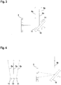
- FIG. 4 shows another example in which light sources 11 that form the illumination unit 5 are arranged on the swivel mirror 10 that forms the deflection unit 7 on the reception side. In this case, the lighting unit 5 is moved with the deflection unit 7 on the receiving side.
- the light sources 11 can be formed by individual light-emitting diodes. Although in Figure 3 only two light sources 11 are shown, of course only one or more than two light sources 11 can be provided.
- Figure 4 shows another example in which the receiving-side deflection unit 7 again consists of the swivel mirror 10.
- the lighting unit 5 is formed by a number of stationary light sources 11. Although only three light sources 11 are shown, a different number of light sources 11 can of course also be provided.
- the light sources 11 are formed by light-emitting diodes and are controlled by the synchronization means 8.
- the light sources 11 emit light beams in different directions. A deflection of the beam direction of the light beams of the lighting unit 5 is achieved in that the synchronization means 8 according to a time sequence selectively activate light sources 11 that emit light in different directions.
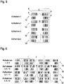
- Figure 5 shows a first example of an object detection with the optical sensor 1 according to Figure 1 .
- Figure 5 shows several objects 12 in adjacent tracks, which are transported on a conveyor, not shown, such as a conveyor belt.
- the objects 12 are each identified by codes A, which are advantageously different.
- the objects 12 are transported on the conveyor belt in a conveying direction (indicated by the arrow I).
- the conveyor speed is controlled by control means of the conveyor belt.
- the conveying movement of the objects 12 is detected by sensors, not shown.
- the control means and / or the external sensors are synchronized with the reception-side deflection unit 7 and the image sensor 2 via the synchronization means 8.
- the light beams are deflected with the deflection unit 7 on the receiving side in the direction indicated by the arrow II, that is to say perpendicular to the conveying speed of the conveyor belt.
- an image field expansion of the image sensor 2 is achieved in such a way that all traces of objects 12 are detected with the optical sensor 1, so that the codes A of all objects 12 can be detected and decoded with the optical sensor 1.
- a swivel range in the conveying direction enables objects 12 to be identified reliably even at high object speeds.
- Figure 6 shows an extension of the example according to Figure 5 such that a two-dimensional deflection takes place with the deflection unit 7 on the receiving side (the individual deflections being identified by the arrows II).
- the image sensor 2 In twelve successive recordings of individual images with the image sensor 2, an overall image is obtained in which there are now twelve objects 12 with codes A.
Landscapes
- Physics & Mathematics (AREA)
- Engineering & Computer Science (AREA)
- General Physics & Mathematics (AREA)
- Electromagnetism (AREA)
- Toxicology (AREA)
- Health & Medical Sciences (AREA)
- General Health & Medical Sciences (AREA)
- Artificial Intelligence (AREA)
- Computer Vision & Pattern Recognition (AREA)
- Theoretical Computer Science (AREA)
- Signal Processing (AREA)
- Multimedia (AREA)
- Optics & Photonics (AREA)
- Computer Networks & Wireless Communication (AREA)
- Radar, Positioning & Navigation (AREA)
- Remote Sensing (AREA)
- Length Measuring Devices By Optical Means (AREA)
Priority Applications (1)
| Application Number | Priority Date | Filing Date | Title |
|---|---|---|---|
| EP18214301.6A EP3671312A1 (fr) | 2018-12-20 | 2018-12-20 | Capteur optique |
Applications Claiming Priority (1)
| Application Number | Priority Date | Filing Date | Title |
|---|---|---|---|
| EP18214301.6A EP3671312A1 (fr) | 2018-12-20 | 2018-12-20 | Capteur optique |
Publications (1)
| Publication Number | Publication Date |
|---|---|
| EP3671312A1 true EP3671312A1 (fr) | 2020-06-24 |
Family
ID=64746296
Family Applications (1)
| Application Number | Title | Priority Date | Filing Date |
|---|---|---|---|
| EP18214301.6A Pending EP3671312A1 (fr) | 2018-12-20 | 2018-12-20 | Capteur optique |
Country Status (1)
| Country | Link |
|---|---|
| EP (1) | EP3671312A1 (fr) |
Citations (6)
| Publication number | Priority date | Publication date | Assignee | Title |
|---|---|---|---|---|
| US20020008849A1 (en) * | 1999-03-16 | 2002-01-24 | O'hagan Paul Allen Peter | Improvements in or relating to lighting systems |
| US20090212217A1 (en) * | 2004-08-04 | 2009-08-27 | Matsushita Electric Industrial Co., Ltd. | Scanning imaging device |
| DE202013009198U1 (de) | 2013-10-18 | 2013-12-02 | Sick Ag | Vorrichtung zum Umlenken und zur Verbreiterung des Sichtbereichs |
| DE102014003348A1 (de) * | 2013-03-08 | 2014-09-11 | Virtek Vision International Inc. | Galvanometer-Abtastkamera mit variablem Fokus und Verfahren |
| US20170195566A1 (en) * | 2016-01-05 | 2017-07-06 | Tdk Taiwan Corp. | Image-capturing device and image-capturing method |
| US20180188523A1 (en) * | 2015-04-17 | 2018-07-05 | Light Labs Inc. | Camera device methods, apparatus and components |
-
2018
- 2018-12-20 EP EP18214301.6A patent/EP3671312A1/fr active Pending
Patent Citations (6)
| Publication number | Priority date | Publication date | Assignee | Title |
|---|---|---|---|---|
| US20020008849A1 (en) * | 1999-03-16 | 2002-01-24 | O'hagan Paul Allen Peter | Improvements in or relating to lighting systems |
| US20090212217A1 (en) * | 2004-08-04 | 2009-08-27 | Matsushita Electric Industrial Co., Ltd. | Scanning imaging device |
| DE102014003348A1 (de) * | 2013-03-08 | 2014-09-11 | Virtek Vision International Inc. | Galvanometer-Abtastkamera mit variablem Fokus und Verfahren |
| DE202013009198U1 (de) | 2013-10-18 | 2013-12-02 | Sick Ag | Vorrichtung zum Umlenken und zur Verbreiterung des Sichtbereichs |
| US20180188523A1 (en) * | 2015-04-17 | 2018-07-05 | Light Labs Inc. | Camera device methods, apparatus and components |
| US20170195566A1 (en) * | 2016-01-05 | 2017-07-06 | Tdk Taiwan Corp. | Image-capturing device and image-capturing method |
Similar Documents
| Publication | Publication Date | Title |
|---|---|---|
| EP0228500B2 (fr) | Méthode et dispositif pour la mesure sans contact du profil d'une roue des roues d'ensembles de roues de voie ferrée | |
| DE69810264T2 (de) | Methode und system zur bewegungsanalyse | |
| DE60213559T2 (de) | Optischer leser mit teilbild-ausschnitt-funktion | |
| EP1645839B1 (fr) | Dispositif et procédé pour surveiller des objets en motion | |
| EP1158460B1 (fr) | Système et procédé de traitement d'images | |
| EP0892280A2 (fr) | Procédé pour faire fonctionner un dispositif capteur opto-électronique | |
| EP2546776A1 (fr) | Lecteur de code basé sur un appareil de prise de vue et son procédé de fabrication ajustée | |
| EP1300691A2 (fr) | Procédé de surveillance et capteur opto-électronique | |
| DE69128634T2 (de) | Bildlesesystem | |
| EP2728305A1 (fr) | Procédé, dispositif et modèle lumineux pour mesurer la hauteur ou le trajet en hauteur d'un objet | |
| EP1586866B1 (fr) | Procédé optoélectronique de déterminer la position d'un capteur pour compenser des erreurs d'ajustement | |
| DE112020006936T5 (de) | Kamerabelichtungsverarbeitungsverfahren und -system | |
| EP1645838B1 (fr) | Dispositif et procédé pour surveiller des objets en motion | |
| EP1813961B1 (fr) | Dispositif destiné à la surveillance optoélectronique d'objets | |
| DE202006020599U1 (de) | Optische Erfassung von bewegten Objekten und Vorrichtung | |
| EP0270062B1 (fr) | Dispositif de prise d'image | |
| EP3671312A1 (fr) | Capteur optique | |
| DE69921230T2 (de) | Optischer Symbolenabtaster | |
| EP2770459B1 (fr) | Lecteur de code optoélectronique et procédé de diagnostic et d'amélioration du procédé de lecture | |
| DE3517671A1 (de) | Vorrichtung zum bildpunktweisen erfassen der oberflaechengestalt eines entfernten objektes | |
| DE10359781B4 (de) | Vorrichtung zur Inspektion von Leergut-Gebinden | |
| DE10118886B4 (de) | Vorrichtung zum optischen Abtasten einer laufenden Warenbahn | |
| DE202006012637U1 (de) | Vorrichtung zum Kollisionsschutz zwischen aufeinanderfolgenden spurgeführten Fahrzeugen | |
| EP3399336B1 (fr) | Dispositif de positionnement | |
| EP3588130B1 (fr) | Capteur optique |
Legal Events
| Date | Code | Title | Description |
|---|---|---|---|
| PUAI | Public reference made under article 153(3) epc to a published international application that has entered the european phase |
Free format text: ORIGINAL CODE: 0009012 |
|
| STAA | Information on the status of an ep patent application or granted ep patent |
Free format text: STATUS: REQUEST FOR EXAMINATION WAS MADE |
|
| 17P | Request for examination filed |
Effective date: 20190815 |
|
| AK | Designated contracting states |
Kind code of ref document: A1 Designated state(s): AL AT BE BG CH CY CZ DE DK EE ES FI FR GB GR HR HU IE IS IT LI LT LU LV MC MK MT NL NO PL PT RO RS SE SI SK SM TR |
|
| AX | Request for extension of the european patent |
Extension state: BA ME |
|
| STAA | Information on the status of an ep patent application or granted ep patent |
Free format text: STATUS: EXAMINATION IS IN PROGRESS |
|
| 17Q | First examination report despatched |
Effective date: 20220930 |
|
| P01 | Opt-out of the competence of the unified patent court (upc) registered |
Free format text: CASE NUMBER: UPC_APP_0011238_3671312/2025 Effective date: 20251028 |