EP3671319B1 - Vorrichtung zur anzeige von stereobildern - Google Patents
Vorrichtung zur anzeige von stereobildern Download PDFInfo
- Publication number
- EP3671319B1 EP3671319B1 EP19218257.4A EP19218257A EP3671319B1 EP 3671319 B1 EP3671319 B1 EP 3671319B1 EP 19218257 A EP19218257 A EP 19218257A EP 3671319 B1 EP3671319 B1 EP 3671319B1
- Authority
- EP
- European Patent Office
- Prior art keywords
- elementary
- pixels
- image
- optical
- longitudinal axis
- Prior art date
- Legal status (The legal status is an assumption and is not a legal conclusion. Google has not performed a legal analysis and makes no representation as to the accuracy of the status listed.)
- Active
Links
Images



Classifications
-
- G—PHYSICS
- G02—OPTICS
- G02B—OPTICAL ELEMENTS, SYSTEMS OR APPARATUS
- G02B30/00—Optical systems or apparatus for producing three-dimensional [3D] effects, e.g. stereoscopic images
- G02B30/20—Optical systems or apparatus for producing three-dimensional [3D] effects, e.g. stereoscopic images by providing first and second parallax images to an observer's left and right eyes
- G02B30/26—Optical systems or apparatus for producing three-dimensional [3D] effects, e.g. stereoscopic images by providing first and second parallax images to an observer's left and right eyes of the autostereoscopic type
-
- G—PHYSICS
- G02—OPTICS
- G02B—OPTICAL ELEMENTS, SYSTEMS OR APPARATUS
- G02B30/00—Optical systems or apparatus for producing three-dimensional [3D] effects, e.g. stereoscopic images
- G02B30/20—Optical systems or apparatus for producing three-dimensional [3D] effects, e.g. stereoscopic images by providing first and second parallax images to an observer's left and right eyes
- G02B30/26—Optical systems or apparatus for producing three-dimensional [3D] effects, e.g. stereoscopic images by providing first and second parallax images to an observer's left and right eyes of the autostereoscopic type
- G02B30/27—Optical systems or apparatus for producing three-dimensional [3D] effects, e.g. stereoscopic images by providing first and second parallax images to an observer's left and right eyes of the autostereoscopic type involving lenticular arrays
-
- H—ELECTRICITY
- H04—ELECTRIC COMMUNICATION TECHNIQUE
- H04N—PICTORIAL COMMUNICATION, e.g. TELEVISION
- H04N13/00—Stereoscopic video systems; Multi-view video systems; Details thereof
- H04N13/10—Processing, recording or transmission of stereoscopic or multi-view image signals
- H04N13/106—Processing image signals
-
- H—ELECTRICITY
- H04—ELECTRIC COMMUNICATION TECHNIQUE
- H04N—PICTORIAL COMMUNICATION, e.g. TELEVISION
- H04N13/00—Stereoscopic video systems; Multi-view video systems; Details thereof
- H04N13/10—Processing, recording or transmission of stereoscopic or multi-view image signals
- H04N13/194—Transmission of image signals
-
- H—ELECTRICITY
- H04—ELECTRIC COMMUNICATION TECHNIQUE
- H04N—PICTORIAL COMMUNICATION, e.g. TELEVISION
- H04N13/00—Stereoscopic video systems; Multi-view video systems; Details thereof
- H04N13/30—Image reproducers
- H04N13/302—Image reproducers for viewing without the aid of special glasses, i.e. using autostereoscopic displays
- H04N13/31—Image reproducers for viewing without the aid of special glasses, i.e. using autostereoscopic displays using parallax barriers
Definitions
- the technical field of the invention is the display of a three-dimensional (3D) image, according to a principle allowing a user a 3D perception from two-dimensional images.
- a screen is optically coupled to an optical separation element.
- the latter makes it possible to project, on the eyes of a user, different views of the same scene.
- the optical separation element can in particular be a lenticular array.
- the screen is then coupled to converging microlenses, for example spherical. The latter make it possible to deflect the light generated by the pixels of the screen, so as to form, at the level of the eyes of a user, a pair of stereoscopic images. One view is formed at one eye, while another view is formed at another eye, the views thus formed forming the stereoscopic pair.
- microlenses are assembled according to an array of microlenses, or lenticular array, usually designated by the term “Micro Lens Array”.
- the useful field of observation is a spatial zone, usually designated by the term “head box”, in which the eyes of a user must be located in order to generate a perception of a three-dimensional image.
- the useful field of observation describes a square, such that the maximum dimension, parallel to the pupillary distance of an observer, is substantially equal to the maximum dimension perpendicular to the axis defining the pupillary distance.
- the document WO98 / 20392 describes the use of an array of microlenses each lens of which is triangular, rectangular or hexagonal, the hexagonal shape being presented as preferred. Indeed, it is considered that the hexagonal shape presents a favorable ratio between the area and the distance separating the center of the hexagon and the point furthest from the hexagon. Thus, hexagonal shaped microlenses are believed to provide better optical performance, in particular a greater depth of field.
- the device described in this document makes it possible to obtain a head box of rectangular shape, the length of which is much greater than the height.
- the inventor has designed a display device making it possible to optimize the useful field of observation, so that the latter is better adapted to the spatial movement of the eyes of a user, while reducing the risk of formation of effects. by Moiré.
- the centers of the elementary zones of the same cell follow a staggered arrangement oriented by the first longitudinal axis and the first lateral axis.
- staggered is meant an arrangement of five centers, four centers being arranged according to the vertices of a parallelogram; the edges of which are parallel to the first lateral axis and / or to the first longitudinal axis, the fifth center being disposed at the center of the parallelogram.
- the parallelogram is for example a rectangle, and preferably a square.
- the first longitudinal axis and the first lateral axis are perpendicular to each other.
- the previously indicated parallelogram is a rectangle. It can also be a square.
- the views can in particular be aligned parallel to the first longitudinal axis and to the first lateral axis.
- the number of pixels belonging to the same elementary zone is strictly greater than 2, and preferably greater than 10 or even greater than 100.
- the image carrier may be a screen, the pixels of which emit light. It can also be a poster.
- Another object of the invention is a method of displaying a set of views on an image plane, using a display device according to the first subject of the invention, the method comprising a generation of 'an image on the image carrier, the generated image being decomposed into elementary images, so that each elementary zone of the image carrier generates an elementary image, so that each view, formed on the image plane, corresponds to the projection of pixels of the same rank of each elementary zone.
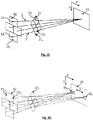
- the figures 1A to 1F show schematically a display device 1 according to the invention.
- the device comprises an image carrier 10, in the form of a matrix of pixels 11 i, j .
- the image support is a screen 10.
- Other examples of image support are indicated at the end of the description.
- the screen pixels are square. In other examples, they can take other geometric shapes, for example diamond-shaped, as shown in the embodiment described in connection with figure 6 .
- the display device 1 also comprises an optical network 20, the latter consisting of optical separation elements 21 i assembled together.
- the optical separation elements 21 i are assembled in a regular pattern.
- the optical network comprises I optical separation elements, preferably identical, connected to each other. I is a natural number generally greater than 10,000, or even greater than 110 6 or greater than 1. 10 7 .
- the optical separation elements 21 i are microlenses, which form an array of microlenses, usually designated by the term MicroLens Array (MLA).
- MLA MicroLens Array
- the optical separation elements are openings made in an opaque mask, each opening forming a diaphragm (or pinhole). Such a configuration is described in connection with the figure 5 .
- the screen extends along a first longitudinal axis X, defining rows, and along a first lateral axis Y, defining columns.
- the first lateral axis Y is perpendicular to the first longitudinal axis X.
- the length of the screen, parallel to the axis X is for example between 10 cm and 2 m, or even more.
- the height of the screen, parallel to the Y axis is for example between 5 cm and 1.5 m, or even more.
- the screen 10 is preferably rectangular in shape.
- the pixels of the screen are arranged in a matrix arrangement. Each pixel on the screen has a center.
- the pixel centers are aligned along lines, parallel to the first longitudinal axis X, and along columns, parallel to the first lateral axis Y. This alignment is also found in the embodiment shown in FIG. figure 6 .
- the screen is a screen of a touch pad. Its dimensions are for example 200 x 160 mm.
- each elementary zone comprises 12 pixels 11 i, j distributed in 3 adjacent rows and 4 columns. It is noted that each elementary zone 12 i of pixels 11 i , j is rectangular, the length, along the first longitudinal axis X, being greater than the height along the first lateral axis Y.
- each pixel ll ij can in particular be a physical pixel, defined by electrodes, the physical pixel corresponding to an elementary display surface of the screen, configured to emit a light signal considered to be of uniform intensity.
- a pixel of an image is a point defining the spatial resolution of the image: it is the smallest constituent element of an image, considered to be of uniform color.
- the notation 11 i , j corresponds to a pixel of rank j in an elementary zone 12 i of index i.
- the rank j of a pixel corresponds to the relative position of the pixel in the elementary zone 12 i to which it belongs.
- the display device 1 is intended to be placed at a distance D from a user, along a transverse axis Z extending perpendicularly to the screen 10.
- the eyes E1, E2 of the user are located in a plane 30. , called the image plane, extending parallel to the screen, along the X and Y axes.
- Each optical separation element 21 i of the optical network 20 is placed facing the screen 10, at a distance d from the latter.
- Each optical separation element 21 i is assigned an index i, so that an optical separation element 21 i is placed facing an elementary zone 12 i .
- each elementary zone 12 i is associated with an optical separation element 21 i facing it, as shown in the figures. figures 1A and 1F .
- each optical separation element 21 i extends around an optical center 23 i , or elementary center, located at the point of intersection of its diagonals. Furthermore, each elementary zone 12 i extends around a center 13 i , defined by the point of intersection of its diagonals. On the figure 1B , the centers 13 i of each elementary zone 12 i have been shown . As shown on the figure 1C , each optical separation element 21 i is centered with respect to the elementary zone 12 i with which it is associated. The term "centered" is understood to mean that the respective centers 13 i , 23 i of an elementary zone 12 i and of an optical separating element 21 i define an optical axis Z i .
- FIG. 1C there is shown the intersection of several optical axes Z i , Z i ' respectively defined by the centers 13 i , 13 i' of elementary zones 12 i , 12 i ' and of the elementary centers 23 i , 23 i' of the elements of optical separation 21 i , 21 i ' associated with said elementary zones.
- the optical axes Z i respectively associated with the different optical separation elements 21 i converge at the same point situated on the image plane 30.
- optical separating element 21 i The function of an optical separating element 21 i is to optically project each pixel ll ij in the image plane 30, so as to form, in the latter, views 31 j adjacent to each other, so that each view corresponds to the superposition of the projections of the pixels ll ij of the same rank j and coming from the different elementary areas 12 i of the screen.
- the optical network 20 is configured such that each optical separating element 21 i projects each pixel 11 i , j respectively in a view 31 j of index j, j corresponding to the rank of the pixel in the elementary zone to which it belongs.
- each optical separation element 21 i is a microlens, making it possible to conjugate each pixel 11 i , j of rank j of an elementary zone 21 i in a view 31 j of index j.
- the figure 1E schematizes a combination of pixels of the same rank j and belonging to different elementary zones 12 i , 12 i ' ..., which makes it possible to form a view 31 j .
- the display device 1 thus allows the simultaneous formation of J views 31 j in the image plane, each view 31 j corresponding to an image formed by a projection of the pixels 11 i , j of the same rank j of each elementary image formed at the level of an elementary zone 12 i . If I denotes the number of elementary zones 12 i which segment the screen 10, and which are respectively associated with an elementary optical separating element 21 i , I also corresponds to the number of pixels respectively conjugated to each view.
- the size of the views 31 j is dimensioned such that the first eye E1 sees a view 31 j , while that the second eye E2 sees a view 31 j ' , with j' ⁇ j.
- the size of a view is inscribed in a diameter corresponding to the diameter of the pupil of an eye. It is therefore inscribed in a diameter of less than 5 mm, and preferably less than 3 mm. According to the principles of stereoscopic vision, view 31 j is different from view 31 j ' .
- each optical separation element in this case each microlens constitutes a pixel of a view 31 j which he perceives at the level of an eye. It will be understood that the size of each optical separation element conditions the spatial resolution of each view 31 j . The spatial resolution of each view is therefore better when the optical separation elements are small.
- each optical separation element 21 i must be able to allow projection of a high number of pixels 11 i , j of the same elementary zone 12 i so as to form J different views 31 j .
- the size of each optical separation element therefore results from a compromise between the spatial resolution of each view 31 j and the number J of different views formed in the image plane 30.
- the pixels 11 i, j of the same elementary zone 12 i emit light with a different intensity or color
- the pixels 11 i, j with 1 i I of the same rank j forming the same view 31 j emit light with the same intensity or the same color
- the number of views 31 j depends on the number of pixels of each elementary zone 12 i .
- the display device allows the formation of J x views along the X axis and of J y views along the Y axis.
- the invention makes it possible to obtain a set of views 32 of rectangular shape when the X axis is perpendicular to the Y axis. More generally, the set of views is parallel to the first longitudinal axis and to the first lateral axis.
- This set of views forms the useful field of observation of the display device 1, that is to say the field of observation in which an observer can perceive 3D information from the views formed.
- the views 31 j are adjacent to one another and form the useful field of observation 32, or field of visibility, usually designated by the English term “head box”.
- the useful field of observation is homothetic for each elementary zone. In the example shown on figures 1A to 1F , the useful field of observation is rectangular.
- the device is designed so that the axis ⁇ connecting the eyes E1 and E2 of the observer is preferably parallel to the first longitudinal axis X.
- the respective positions of the user's eyes E1 and E2 are more likely to move parallel to the X axis, than parallel to the Y axis.
- the observation range of a user is higher when the user turns his head parallel to the ⁇ axis, than perpendicular to the ⁇ axis.
- the invention makes it possible to maximize the number of views formed along the X axis with respect to the numbers of views formed parallel to the Y axis.
- the fact of having elementary rectangular areas 12 i therefore makes it possible to optimize the shape of the head box, that is to say of the useful field of observation 32 formed by the display device 1 in the image plane 30.
- the distance between an observer's pupils, or pupillary distance is generally close to 65 mm.
- the inventor considered that the optimal shape of the head-box can be a rectangle 130 mm long along the X axis and 65 mm high along the Y axis, or more generally a rectangle whose height (along the axis Y) is less than 2/3 of the length (along the X axis). It seems optimal that the height is substantially equal to half the length, the term substantially meaning to the nearest 10% or to the nearest 20%.
- the number J of pixels forming an elementary zone 12 i corresponds to the numbers of views 31 j formed on the image plane. It also corresponds to a ratio between the area of the head box 32 on the area of each elementary view.
- the number of pixels forming the screen being limited, it is important to optimize the number of views formed, taking into account the potential displacements of the eyes of a user.
- a configuration based on elementary rectangular areas 12 i makes it possible to optimize the spatial distribution of the views, taking into account the fact that the eyes of an observer are moved. More parallel to the ⁇ axis, that is to say from right to left (or from left to right) than perpendicular to the latter, from top to bottom or from bottom to top.
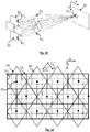
- the elementary areas 12 i are aligned in a brick wall arrangement. This is achieved by placing the respective centers of the elementary zones in a staggered pattern. Thus, it is possible to define a mesh 14 of five elementary zones 12 i , the respective centers of which 13 i, a , 13 i, b , 13 i, c 13 i, d and 13 i, e are arranged in a staggered fashion.
- Mesh 14 comprises a central elementary zone 12 i, a , with center 13 i, a and four adjacent elementary zones 12 i, b , 12 i, c 12 i, d and 12 i, e , with respective centers 13 i, b , 13 i , c 13 i , d and 13 i, e , aligned, two by two, on adjacent lines respectively on the part and of the central elementary zone.
- the staggered arrangement is characterized by the fact that the centers 13 i, b , 13 i, c 13i, d and 13 i, e of the adjacent elementary zones 12 i, b , 12 i, c 12 i, d and 12 i, e form the vertices of a parallelogram, while the center 13 i, a of the central elementary zone 12 i, a is arranged at the center of the parallelogram.
- the parallelogram may be a rectangle, or even a square.
- An elementary cell 14 is represented in gray on the figure 1B , as well as on figures 2A, 2B and 4 .
- the staggered arrangement favors the arrangement of the optical separation elements 21 i . This facilitates centering of each optical separation element 21 i facing the elementary zone 12 i with which it is associated.
- the optical network 20 can then include optical separation elements 21 i arranged in a regular pattern.
- the staggered arrangement is particularly suitable for the embodiment described in connection with the figures 2A and 2B .
- substantially equal means equal assuming an angular tolerance near, for example ⁇ 5 °.
- Such a configuration makes it possible to form elementary zones whose length (parallel to the X axis) is twice the height (parallel to the Y axis).
- the length of each elementary zone 12 i corresponds, up to a homothetic factor, to a diagonal of the square forming the optical separation element 21 i with which it is associated.
- This also makes it possible to obtain an observation zone 32 (head box), the length of which is two times greater than the height.
- the inventor considered that such a ratio was particularly suitable for use in which the screen is the screen of a tablet or of a television set.
- the elementary zones 12 i can be reconfigured, as shown in the figure. figure 2B .
- the reconfiguration makes it possible to maintain a head box 32 whose height (in this configuration, along the X axis) is twice the length (along the Y axis).
- Rotating the screen 90 ° can be a useful feature when the screen is the screen of a tablet held in the user's hands.
- the tablet comprises a processing unit, connected to an orientation sensor, to allow the configuration of the elementary zones according to the orientation of the screen.
- the inventor has dimensioned an example of a display device in which the optical separation elements are square microlenses, as shown in the figure. figure 2A .
- the optical network 20 is formed by square microlenses with a side 350 ⁇ m forming a matrix of microlenses.
- Each lens is arranged such that its diagonals are respectively parallel to the first longitudinal axis X and to the first lateral axis Y of the screen.
- the distance D between the observer, that is to say the image plane 30, and the array of microlenses 20, is fixed at 500 mm.
- Such a screen is produced by associating 36 micro-screens in a matrix of 6 rows and 6 columns.
- the lenses 21 i are diamonds, the square being a particular case of a diamond.
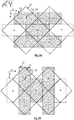
- the lenses, or more generally the optical separation elements 21 i may have a hexagonal shape, as illustrated in FIG. figure 4 .
- the center of the optical separation element corresponds to the intersection of at least three diagonals, the intersection being not coincident with a vertex of the hexagon.
- the figure 4 there is shown, in dotted lines, three diagonals of a hexagon whose intersection is common and is not confused with a vertex.
- elementary areas 12 i of the screen On the figure 4 , there is shown, in dotted lines, elementary areas 12 i of the screen.
- the hexagon is preferably a regular hexagon.
- at least one diagonal of the optical separation element is preferably parallel to the first longitudinal axis X or to the first lateral axis Y.
- the optical separation element has two diagonals respectively parallel to the longitudinal axis X and to the lateral axis Y.
- the figure 4 there is shown, also in dotted lines, diagonals respectively parallel to the X axis and to the Y axis.
- the optical network 20 consists of an opaque mask in which openings 21 i are formed, the center of which 23 i is aligned with respect to the center 13 i of an elementary zone 12 i .
- Each opening forms an optical separation element 21 i of the diaphragm or pinhole type.
- the size and spacing of the apertures depends on the distance D between the user and the optical network 20. It is preferable that the angular difference between two adjacent apertures is less than 1 mrad (milliradian). It is preferable that the diameter of each opening is at least 5 times smaller than the spacing between the holes.
- Such an optical grating 20 has an infinite depth of field, but the quantity of light projected on the image plane 30 is less important than by using an array of microlenses.
- Such an optical network is represented on the figure 5 . The light collection efficiency can be increased by placing a microlens at each opening. The optical network then comprises microlenses distant from each other.
- the pixels 11 i, j of the screen are inscribed in diamonds, aligned along the first longitudinal axis X and along the first lateral axis Y.
- each elementary zone 12 i comprises peripheral pixels, the respective centers of which are aligned with the outline of a rectangle. Such a rectangle is shown in dotted lines on the figure 6 .
- the invention can be applied to larger devices, for example television or cinema screens.
- the length of the screen, along the longitudinal axis X, can then exceed 1 meter, or even 10 meters, the height being adjusted as a function of the screen format.
- the image medium can be any means allowing the display of an image. It may be a printed panel, for example a poster, or a screen receiving an image projected by a projector.
- the pixels can be of very small size, for example less than 1 ⁇ m 2 .
- It can also be a support on which a coating has been applied, for example a paint.
- the support can be a wall, or a surface of an everyday object, for example a decorative object, or a sign.
Landscapes
- Physics & Mathematics (AREA)
- Engineering & Computer Science (AREA)
- Multimedia (AREA)
- Signal Processing (AREA)
- General Physics & Mathematics (AREA)
- Optics & Photonics (AREA)
- Testing, Inspecting, Measuring Of Stereoscopic Televisions And Televisions (AREA)
- Stereoscopic And Panoramic Photography (AREA)
Claims (18)
- Anzeigevorrichtung (1), die einen Bildträger (10) umfasst, der durch eine Pixelmatrix (11i;j) gebildet ist, wobei sich jedes Pixel um eine Mitte erstreckt, wobei die Matrix dergestalt ist, dass sich Pixelmitten gemäß Zeilen parallel zu einer ersten Längsachse (X) und gemäß Spalten parallel zu einer ersten Querachse (Y) erstrecken, wobei der Bildträger gegenüber einem optischen Array (20) angeordnet ist, wobei die Vorrichtung dergestalt ist, dass:- der Bildträger in Elementarbereiche (12i) unterteilt ist, wobei jedem Elementarbereich eine vorgegebene Anzahl von benachbarten Pixeln (11i;j) entspricht, wobei jeder Elementarbereich dazu konfiguriert ist, ein Elementarbild anzuzeigen;- das optische Array (20) optische Trennelemente (21i) umfasst, wobei jedes optische Trennelement dazu konfiguriert ist, die Pixel (11i;j) auf eine Bildebene (30) zu projizieren, die von dem Bildträger entfernt und zu diesem parallel ist;- jeder Elementarbereich eine Untermatrix bildet und Pixel (11i;j) umfasst, wobei mit jedem Pixel ein Rang (j) assoziiert ist, der einer Position des Pixels in der Untermatrix entspricht;- das optische Array dazu konfiguriert ist, Ansichten (31j) in der Bildebene (30) zu bilden, wobei jede Ansicht durch Projektionen von Pixeln (11i;j) desselben Ranges (j), die sich in unterschiedlichen Elementarbereichen (12i) befinden, gebildet wird;- sich jeder Elementarbereich um eine Mitte (13i) erstreckt;- jedes optische Trennelement (21i) mit einem Elementarbereich (12i) assoziiert ist und sich um eine Elementarmitte (23i) erstreckt, wobei jedes optische Trennelement so angeordnet ist, dass eine optische Achse (Zi) definiert wird, die sich zwischen der Elementarmitte (23i) und der Mitte des Elementarbereichs (12i), der mit dem optischen Trennelement assoziiert ist, erstreckt;- die optischen Achsen (Zi) der unterschiedlichen optischen Trennelemente (21i) in einem gleichen Punkt der Bildebene (30) konvergieren;wobei die Vorrichtung dadurch gekennzeichnet ist, dass:- sich jeder Elementarbereich (12i) gemäß einer Länge parallel zu der ersten Längsachse und einer Höhe parallel zu der ersten Querachse erstreckt, wobei die Länge in jedem Fall größer als die Höhe ist;- die Elementarbereiche gemäß Maschen (14) eingerichtet sind, wobei jede Masche einen mittigen Elementarbereich und vier dazu benachbarte Elementarbereiche umfasst, wobei jede Masche dergestalt ist, dass die Mitten der Elementarbereiche einer gleichen Masche eine Fünfpunktanordnung bilden.
- Vorrichtung nach Anspruch 1, wobei jeder Elementarbereich (12i) mehr als 2 Pixel und vorzugsweise mehr als 5 oder 10 Pixel umfasst.
- Vorrichtung nach einem der vorhergehenden Ansprüche, wobei jeder Elementarbereich (12i) rechteckig ist und/oder wobei die Mitten der Pixel, die sich am Umfang jedes Elementarbereichs befinden, gemäß den Konturen eines Rechtecks ausgerichtet sind.
- Vorrichtung nach einem der vorhergehenden Ansprüche, wobei jedes optische Trennelement (21i) einen polygonalen Querschnitt und insbesondere einen quadratischen oder rautenförmigen oder sechseckigen Querschnitt aufweist.
- Vorrichtung nach Anspruch 4, wobei sich mindestens eine Diagonale jedes optischen Trennelements (21i) jeweils parallel zu der ersten Längsachse X oder zu der ersten Querachse Y erstreckt.
- Vorrichtung nach einem der vorhergehenden Ansprüche, wobei Ränder von zwei benachbarten optischen Trennelementen parallel zu Folgendem ausgerichtet sind:- einer zweiten Längsachse (X'), wobei die zweite Längsachse in einer Ebene, die durch die erste Längsachse (X) und die erste Querachse (Y) definiert wird, mit Bezug auf die erste Längsachse (X) einen spitzen Winkel (θx) bildet;- oder einer zweiten Querachse (Y'), wobei die zweite Querachse in einer Ebene, die durch die erste Längsachse (X) und die erste Querachse (Y) definiert wird, mit Bezug auf die erste Querachse (Y) einen spitzen Winkel (θy) bildet.
- Vorrichtung nach Anspruch 6, wobei jedes optische Trennelement ein Quadrat ist, sodass die zweite Längsachse (X') mit Bezug auf die erste Längsachse (X) um 45° geneigt ist und die zweite Querachse (Y') mit Bezug auf die erste Querachse (Y) um 45° geneigt ist.
- Vorrichtung nach einem der vorhergehenden Ansprüche, wobei jedes optische Trennelement (21i) eine Mikrolinse ist, sodass das optische Array (20) eine Matrix aus Mikrolinsen ist.
- Vorrichtung nach einem der Ansprüche 1 bis 6, wobei jedes optische Trennelement (21i) eine Öffnung ist, die in einer lichtundurchlässigen Maske gebildet ist.
- Vorrichtung nach Anspruch 9, wobei sich jede Öffnung innerhalb eines Kreises mit einem Durchmesser kleiner als oder gleich 1 mm befindet.
- Vorrichtung nach einem der vorhergehenden Ansprüche, wobei die Ansichten (31j), die jeweils durch die Projektion der Pixel (11i;j) der Elementarbereiche (12i) gebildet werden, benachbart sind und eine Gesamtheit von Ansichten (32) bilden, welche ein nutzbares Sehfeld bildet, das sich gemäß einer rechteckigen Fläche parallel zu dem Bildträger (10) erstreckt.
- Vorrichtung nach Anspruch 11, die so konfiguriert ist, dass sich die Gesamtheit von Ansichten (32) gemäß einer Länge parallel zu der ersten Längsachse (X) und gemäß einer Höhe gemäß der ersten Querachse (Y) erstreckt, wobei die Höhe vorzugsweise weniger als zwei Drittel der Länge beträgt.
- Vorrichtung nach Anspruch 12, die so konfiguriert ist, dass die Höhe der Gesamtheit von Ansichten (32), auf weniger als ± 20 % genau, gleich der Hälfte ihrer Länge ist.
- Verfahren zum Anzeigen einer Gesamtheit von Ansichten (32) auf einer Bildebene (30) mit Hilfe einer Anzeigevorrichtung (1) nach einem der vorhergehenden Ansprüche, wobei das Verfahren eine Erzeugung eines Bildes auf dem Bildträger umfasst, wobei das erzeugte Bild in Elementarbilder zerlegt wird, sodass jeder Elementarbereich (12i) des Bildträgers ein Elementarbild erzeugt, sodass jede Ansicht (31j), die in der Bildebene gebildet wird, der Projektion von Pixeln (11i;j) desselben Ranges (j) jedes Elementarbereichs entspricht.
- Verfahren nach Anspruch 14, wobei die Pixel (11i;j) eines gleichen Elementarbereichs (12i) dazu konfiguriert sind, das Elementarbild, das dem Elementarbereich entspricht, mit unterschiedlichen Intensitäten oder unterschiedlichen Farben anzuzeigen.
- Verfahren nach einem der Ansprüche 14 oder 15, wobei der Abstand zwischen dem Bildträger (10) und der Bildebene (30) zwischen 30 cm und 3 Metern liegt.
- Verfahren nach einem der Ansprüche 14 bis 16, wobei sich die Gesamtheit von Ansichten (32) gemäß einem Rechteck parallel zu der ersten Längsachse (X) und zu der ersten Querachse (Y) erstreckt.
- Verfahren nach Anspruch 17, wobei sich das Rechteck folgendermaßen erstreckt:- parallel zu der ersten Längsachse (X) gemäß einer Länge, die beispielsweise zwischen 70 mm und 200 mm liegt;- parallel zu der ersten Querachse (Y) gemäß einer Höhe, die weniger als zwei Drittel der Länge beträgt.
Applications Claiming Priority (1)
| Application Number | Priority Date | Filing Date | Title |
|---|---|---|---|
| FR1874084A FR3090908B1 (fr) | 2018-12-22 | 2018-12-22 | Dispositif d'affichage d'images stéréoscopiques |
Publications (2)
| Publication Number | Publication Date |
|---|---|
| EP3671319A1 EP3671319A1 (de) | 2020-06-24 |
| EP3671319B1 true EP3671319B1 (de) | 2021-09-08 |
Family
ID=66676788
Family Applications (1)
| Application Number | Title | Priority Date | Filing Date |
|---|---|---|---|
| EP19218257.4A Active EP3671319B1 (de) | 2018-12-22 | 2019-12-19 | Vorrichtung zur anzeige von stereobildern |
Country Status (3)
| Country | Link |
|---|---|
| US (1) | US11092818B2 (de) |
| EP (1) | EP3671319B1 (de) |
| FR (1) | FR3090908B1 (de) |
Families Citing this family (1)
| Publication number | Priority date | Publication date | Assignee | Title |
|---|---|---|---|---|
| CN112859368B (zh) * | 2021-04-01 | 2022-11-15 | 成都航空职业技术学院 | 基于阶梯渐变孔径针孔阵列的双视3d显示方法 |
Family Cites Families (15)
| Publication number | Priority date | Publication date | Assignee | Title |
|---|---|---|---|---|
| FR2705008B1 (fr) | 1993-05-05 | 1995-07-21 | Le Particulier Editions Sa | Dispositif et systeme video autostereoscopique |
| GB9513658D0 (en) * | 1995-07-05 | 1995-09-06 | Philips Electronics Uk Ltd | Autostereoscopic display apparatus |
| GB2309609A (en) * | 1996-01-26 | 1997-07-30 | Sharp Kk | Observer tracking autostereoscopic directional display |
| FR2755519A1 (fr) | 1996-11-07 | 1998-05-07 | Guigan Franck Andre Marie | Ecran statique pour images animees |
| KR100389249B1 (ko) * | 2000-04-29 | 2003-06-25 | 한국과학기술연구원 | 다시점 영상 표시 시스템 |
| US20110038043A1 (en) * | 2009-08-17 | 2011-02-17 | Industrial Technology Research Institute | Segmented lenticular array used in autostereoscopic display apparatus |
| JP6149339B2 (ja) * | 2010-06-16 | 2017-06-21 | 株式会社ニコン | 表示装置 |
| TWI452345B (zh) * | 2012-10-26 | 2014-09-11 | Au Optronics Corp | 立體顯示器及其顯示方法 |
| CN105492959B (zh) * | 2013-09-03 | 2019-02-19 | 皇家飞利浦有限公司 | 多视图显示设备 |
| KR102218777B1 (ko) * | 2014-09-11 | 2021-02-19 | 엘지디스플레이 주식회사 | 무안경 입체영상표시장치 |
| CN105676464B (zh) * | 2014-12-08 | 2018-08-24 | 松下知识产权经营株式会社 | 图像显示装置 |
| BR112017013572B1 (pt) * | 2014-12-24 | 2021-03-02 | Koninklijke Philips N.V | tela autoestereoscópica, e dispositivo portátil |
| KR102284841B1 (ko) * | 2014-12-26 | 2021-08-03 | 엘지디스플레이 주식회사 | 무안경 입체영상표시장치 |
| KR102423398B1 (ko) * | 2015-10-30 | 2022-07-20 | 엘지디스플레이 주식회사 | 무안경 3d 표시장치 |
| KR101760453B1 (ko) * | 2016-01-18 | 2017-07-24 | 한국과학기술연구원 | 변형 서브화소 구조를 갖는 무안경식 3차원 영상표시장치 |
-
2018
- 2018-12-22 FR FR1874084A patent/FR3090908B1/fr not_active Expired - Fee Related
-
2019
- 2019-12-19 EP EP19218257.4A patent/EP3671319B1/de active Active
- 2019-12-20 US US16/722,098 patent/US11092818B2/en active Active
Also Published As
| Publication number | Publication date |
|---|---|
| US20200201066A1 (en) | 2020-06-25 |
| FR3090908A1 (fr) | 2020-06-26 |
| FR3090908B1 (fr) | 2020-12-25 |
| EP3671319A1 (de) | 2020-06-24 |
| US11092818B2 (en) | 2021-08-17 |
Similar Documents
| Publication | Publication Date | Title |
|---|---|---|
| US8279507B2 (en) | Hologram and holgraphic viewing device incorporating it | |
| EP2798396B1 (de) | Verfahren zur herstellung einer sicherheitsvorrichtung | |
| EP2895914B1 (de) | Anzeigebildschirm für autostereoskopie | |
| EP0717911B1 (de) | Farbanzeigevorrichtung | |
| EP3233517B1 (de) | Sicherheitsvorrichtung mit einem linsenarray mit mehreren geätzten farbmustern | |
| CN113325598B (zh) | 3d显示装置 | |
| CN109073939A (zh) | 提供增强的观看体验的近眼图像显示设备 | |
| CN110737104A (zh) | 基于变焦微透镜阵列的显示系统 | |
| EP3671319B1 (de) | Vorrichtung zur anzeige von stereobildern | |
| KR102704962B1 (ko) | 렌즈 패널 및 이를 포함하는 표시 장치 | |
| CN104423053B (zh) | 一种可同时显示2d与3d影像的装置 | |
| FR2891062A1 (fr) | Ecran a reseau de systemes optiques centres | |
| NO314862B1 (no) | Automultiskopisk skjerm med bildeelementmatrise og optisk system, samt beslektede mikrolinseanvendelser | |
| EP3723995B1 (de) | Anordnung aus einer komplexen transparenzvorrichtung und mindestens einer anordnung von mikrobildern sowie sicherheitsdokument mit solch einer anordnung | |
| FR2888000A1 (fr) | Procede d'aide au positionnement, et dispositif de visualisation autostereoscopique implementant ce procede | |
| EP3298440A1 (de) | Bildgenerator, insbesondere für head-up-anzeigevorrichtung | |
| FR3105091A1 (fr) | Procédé de fabrication d’un dispositif de sécurité et dispositif de sécurité associé | |
| WO2024141183A1 (fr) | Ecran autostereoscopique, dit de qualite photographique | |
| FR2891059A1 (fr) | Ecran 3d a reseau de systemes optiques centres | |
| FR2974930A1 (fr) | Procede de fabrication d'une image iridescente, image obtenue et dispositif la comprenant, programme associe | |
| JP2012073645A (ja) | ホログラム観察法 | |
| FR2891063A1 (fr) | Ecran electronique a reseau lenticulaire en nid d'abeilles |
Legal Events
| Date | Code | Title | Description |
|---|---|---|---|
| PUAI | Public reference made under article 153(3) epc to a published international application that has entered the european phase |
Free format text: ORIGINAL CODE: 0009012 |
|
| STAA | Information on the status of an ep patent application or granted ep patent |
Free format text: STATUS: REQUEST FOR EXAMINATION WAS MADE |
|
| 17P | Request for examination filed |
Effective date: 20191219 |
|
| AK | Designated contracting states |
Kind code of ref document: A1 Designated state(s): AL AT BE BG CH CY CZ DE DK EE ES FI FR GB GR HR HU IE IS IT LI LT LU LV MC MK MT NL NO PL PT RO RS SE SI SK SM TR |
|
| GRAP | Despatch of communication of intention to grant a patent |
Free format text: ORIGINAL CODE: EPIDOSNIGR1 |
|
| STAA | Information on the status of an ep patent application or granted ep patent |
Free format text: STATUS: GRANT OF PATENT IS INTENDED |
|
| RIC1 | Information provided on ipc code assigned before grant |
Ipc: G02B 30/27 20200101ALI20210305BHEP Ipc: G02B 27/20 20060101AFI20210305BHEP |
|
| INTG | Intention to grant announced |
Effective date: 20210330 |
|
| GRAS | Grant fee paid |
Free format text: ORIGINAL CODE: EPIDOSNIGR3 |
|
| GRAA | (expected) grant |
Free format text: ORIGINAL CODE: 0009210 |
|
| STAA | Information on the status of an ep patent application or granted ep patent |
Free format text: STATUS: THE PATENT HAS BEEN GRANTED |
|
| AK | Designated contracting states |
Kind code of ref document: B1 Designated state(s): AL AT BE BG CH CY CZ DE DK EE ES FI FR GB GR HR HU IE IS IT LI LT LU LV MC MK MT NL NO PL PT RO RS SE SI SK SM TR |
|
| REG | Reference to a national code |
Ref country code: GB Ref legal event code: FG4D Free format text: NOT ENGLISH |
|
| REG | Reference to a national code |
Ref country code: CH Ref legal event code: EP Ref country code: AT Ref legal event code: REF Ref document number: 1429087 Country of ref document: AT Kind code of ref document: T Effective date: 20210915 |
|
| REG | Reference to a national code |
Ref country code: DE Ref legal event code: R096 Ref document number: 602019007559 Country of ref document: DE |
|
| REG | Reference to a national code |
Ref country code: IE Ref legal event code: FG4D Free format text: LANGUAGE OF EP DOCUMENT: FRENCH |
|
| REG | Reference to a national code |
Ref country code: LT Ref legal event code: MG9D |
|
| REG | Reference to a national code |
Ref country code: NL Ref legal event code: MP Effective date: 20210908 |
|
| PG25 | Lapsed in a contracting state [announced via postgrant information from national office to epo] |
Ref country code: SE Free format text: LAPSE BECAUSE OF FAILURE TO SUBMIT A TRANSLATION OF THE DESCRIPTION OR TO PAY THE FEE WITHIN THE PRESCRIBED TIME-LIMIT Effective date: 20210908 Ref country code: RS Free format text: LAPSE BECAUSE OF FAILURE TO SUBMIT A TRANSLATION OF THE DESCRIPTION OR TO PAY THE FEE WITHIN THE PRESCRIBED TIME-LIMIT Effective date: 20210908 Ref country code: ES Free format text: LAPSE BECAUSE OF FAILURE TO SUBMIT A TRANSLATION OF THE DESCRIPTION OR TO PAY THE FEE WITHIN THE PRESCRIBED TIME-LIMIT Effective date: 20210908 Ref country code: LT Free format text: LAPSE BECAUSE OF FAILURE TO SUBMIT A TRANSLATION OF THE DESCRIPTION OR TO PAY THE FEE WITHIN THE PRESCRIBED TIME-LIMIT Effective date: 20210908 Ref country code: BG Free format text: LAPSE BECAUSE OF FAILURE TO SUBMIT A TRANSLATION OF THE DESCRIPTION OR TO PAY THE FEE WITHIN THE PRESCRIBED TIME-LIMIT Effective date: 20211208 Ref country code: NO Free format text: LAPSE BECAUSE OF FAILURE TO SUBMIT A TRANSLATION OF THE DESCRIPTION OR TO PAY THE FEE WITHIN THE PRESCRIBED TIME-LIMIT Effective date: 20211208 Ref country code: HR Free format text: LAPSE BECAUSE OF FAILURE TO SUBMIT A TRANSLATION OF THE DESCRIPTION OR TO PAY THE FEE WITHIN THE PRESCRIBED TIME-LIMIT Effective date: 20210908 Ref country code: FI Free format text: LAPSE BECAUSE OF FAILURE TO SUBMIT A TRANSLATION OF THE DESCRIPTION OR TO PAY THE FEE WITHIN THE PRESCRIBED TIME-LIMIT Effective date: 20210908 |
|
| REG | Reference to a national code |
Ref country code: AT Ref legal event code: MK05 Ref document number: 1429087 Country of ref document: AT Kind code of ref document: T Effective date: 20210908 |
|
| PG25 | Lapsed in a contracting state [announced via postgrant information from national office to epo] |
Ref country code: LV Free format text: LAPSE BECAUSE OF FAILURE TO SUBMIT A TRANSLATION OF THE DESCRIPTION OR TO PAY THE FEE WITHIN THE PRESCRIBED TIME-LIMIT Effective date: 20210908 Ref country code: GR Free format text: LAPSE BECAUSE OF FAILURE TO SUBMIT A TRANSLATION OF THE DESCRIPTION OR TO PAY THE FEE WITHIN THE PRESCRIBED TIME-LIMIT Effective date: 20211209 |
|
| PG25 | Lapsed in a contracting state [announced via postgrant information from national office to epo] |
Ref country code: AT Free format text: LAPSE BECAUSE OF FAILURE TO SUBMIT A TRANSLATION OF THE DESCRIPTION OR TO PAY THE FEE WITHIN THE PRESCRIBED TIME-LIMIT Effective date: 20210908 |
|
| PG25 | Lapsed in a contracting state [announced via postgrant information from national office to epo] |
Ref country code: IS Free format text: LAPSE BECAUSE OF FAILURE TO SUBMIT A TRANSLATION OF THE DESCRIPTION OR TO PAY THE FEE WITHIN THE PRESCRIBED TIME-LIMIT Effective date: 20220108 Ref country code: SM Free format text: LAPSE BECAUSE OF FAILURE TO SUBMIT A TRANSLATION OF THE DESCRIPTION OR TO PAY THE FEE WITHIN THE PRESCRIBED TIME-LIMIT Effective date: 20210908 Ref country code: SK Free format text: LAPSE BECAUSE OF FAILURE TO SUBMIT A TRANSLATION OF THE DESCRIPTION OR TO PAY THE FEE WITHIN THE PRESCRIBED TIME-LIMIT Effective date: 20210908 Ref country code: RO Free format text: LAPSE BECAUSE OF FAILURE TO SUBMIT A TRANSLATION OF THE DESCRIPTION OR TO PAY THE FEE WITHIN THE PRESCRIBED TIME-LIMIT Effective date: 20210908 Ref country code: PT Free format text: LAPSE BECAUSE OF FAILURE TO SUBMIT A TRANSLATION OF THE DESCRIPTION OR TO PAY THE FEE WITHIN THE PRESCRIBED TIME-LIMIT Effective date: 20220110 Ref country code: PL Free format text: LAPSE BECAUSE OF FAILURE TO SUBMIT A TRANSLATION OF THE DESCRIPTION OR TO PAY THE FEE WITHIN THE PRESCRIBED TIME-LIMIT Effective date: 20210908 Ref country code: NL Free format text: LAPSE BECAUSE OF FAILURE TO SUBMIT A TRANSLATION OF THE DESCRIPTION OR TO PAY THE FEE WITHIN THE PRESCRIBED TIME-LIMIT Effective date: 20210908 Ref country code: EE Free format text: LAPSE BECAUSE OF FAILURE TO SUBMIT A TRANSLATION OF THE DESCRIPTION OR TO PAY THE FEE WITHIN THE PRESCRIBED TIME-LIMIT Effective date: 20210908 Ref country code: CZ Free format text: LAPSE BECAUSE OF FAILURE TO SUBMIT A TRANSLATION OF THE DESCRIPTION OR TO PAY THE FEE WITHIN THE PRESCRIBED TIME-LIMIT Effective date: 20210908 Ref country code: AL Free format text: LAPSE BECAUSE OF FAILURE TO SUBMIT A TRANSLATION OF THE DESCRIPTION OR TO PAY THE FEE WITHIN THE PRESCRIBED TIME-LIMIT Effective date: 20210908 |
|
| REG | Reference to a national code |
Ref country code: DE Ref legal event code: R097 Ref document number: 602019007559 Country of ref document: DE |
|
| PLBE | No opposition filed within time limit |
Free format text: ORIGINAL CODE: 0009261 |
|
| STAA | Information on the status of an ep patent application or granted ep patent |
Free format text: STATUS: NO OPPOSITION FILED WITHIN TIME LIMIT |
|
| PG25 | Lapsed in a contracting state [announced via postgrant information from national office to epo] |
Ref country code: MC Free format text: LAPSE BECAUSE OF FAILURE TO SUBMIT A TRANSLATION OF THE DESCRIPTION OR TO PAY THE FEE WITHIN THE PRESCRIBED TIME-LIMIT Effective date: 20210908 Ref country code: DK Free format text: LAPSE BECAUSE OF FAILURE TO SUBMIT A TRANSLATION OF THE DESCRIPTION OR TO PAY THE FEE WITHIN THE PRESCRIBED TIME-LIMIT Effective date: 20210908 |
|
| 26N | No opposition filed |
Effective date: 20220609 |
|
| PG25 | Lapsed in a contracting state [announced via postgrant information from national office to epo] |
Ref country code: SI Free format text: LAPSE BECAUSE OF FAILURE TO SUBMIT A TRANSLATION OF THE DESCRIPTION OR TO PAY THE FEE WITHIN THE PRESCRIBED TIME-LIMIT Effective date: 20210908 |
|
| REG | Reference to a national code |
Ref country code: BE Ref legal event code: MM Effective date: 20211231 |
|
| PG25 | Lapsed in a contracting state [announced via postgrant information from national office to epo] |
Ref country code: LU Free format text: LAPSE BECAUSE OF NON-PAYMENT OF DUE FEES Effective date: 20211219 Ref country code: IE Free format text: LAPSE BECAUSE OF NON-PAYMENT OF DUE FEES Effective date: 20211219 |
|
| PG25 | Lapsed in a contracting state [announced via postgrant information from national office to epo] |
Ref country code: BE Free format text: LAPSE BECAUSE OF NON-PAYMENT OF DUE FEES Effective date: 20211231 |
|
| PG25 | Lapsed in a contracting state [announced via postgrant information from national office to epo] |
Ref country code: IT Free format text: LAPSE BECAUSE OF FAILURE TO SUBMIT A TRANSLATION OF THE DESCRIPTION OR TO PAY THE FEE WITHIN THE PRESCRIBED TIME-LIMIT Effective date: 20210908 |
|
| PG25 | Lapsed in a contracting state [announced via postgrant information from national office to epo] |
Ref country code: CY Free format text: LAPSE BECAUSE OF FAILURE TO SUBMIT A TRANSLATION OF THE DESCRIPTION OR TO PAY THE FEE WITHIN THE PRESCRIBED TIME-LIMIT Effective date: 20210908 |
|
| PG25 | Lapsed in a contracting state [announced via postgrant information from national office to epo] |
Ref country code: HU Free format text: LAPSE BECAUSE OF FAILURE TO SUBMIT A TRANSLATION OF THE DESCRIPTION OR TO PAY THE FEE WITHIN THE PRESCRIBED TIME-LIMIT; INVALID AB INITIO Effective date: 20191219 |
|
| REG | Reference to a national code |
Ref country code: CH Ref legal event code: PL |
|
| PG25 | Lapsed in a contracting state [announced via postgrant information from national office to epo] |
Ref country code: LI Free format text: LAPSE BECAUSE OF NON-PAYMENT OF DUE FEES Effective date: 20221231 Ref country code: CH Free format text: LAPSE BECAUSE OF NON-PAYMENT OF DUE FEES Effective date: 20221231 |
|
| PG25 | Lapsed in a contracting state [announced via postgrant information from national office to epo] |
Ref country code: MK Free format text: LAPSE BECAUSE OF FAILURE TO SUBMIT A TRANSLATION OF THE DESCRIPTION OR TO PAY THE FEE WITHIN THE PRESCRIBED TIME-LIMIT Effective date: 20210908 |
|
| PG25 | Lapsed in a contracting state [announced via postgrant information from national office to epo] |
Ref country code: MT Free format text: LAPSE BECAUSE OF FAILURE TO SUBMIT A TRANSLATION OF THE DESCRIPTION OR TO PAY THE FEE WITHIN THE PRESCRIBED TIME-LIMIT Effective date: 20210908 |
|
| PGFP | Annual fee paid to national office [announced via postgrant information from national office to epo] |
Ref country code: GB Payment date: 20241227 Year of fee payment: 6 |
|
| PGFP | Annual fee paid to national office [announced via postgrant information from national office to epo] |
Ref country code: FR Payment date: 20241227 Year of fee payment: 6 |
|
| PGFP | Annual fee paid to national office [announced via postgrant information from national office to epo] |
Ref country code: DE Payment date: 20241219 Year of fee payment: 6 |
|
| PG25 | Lapsed in a contracting state [announced via postgrant information from national office to epo] |
Ref country code: TR Free format text: LAPSE BECAUSE OF FAILURE TO SUBMIT A TRANSLATION OF THE DESCRIPTION OR TO PAY THE FEE WITHIN THE PRESCRIBED TIME-LIMIT Effective date: 20210908 |