EP3671376A1 - Sensoren-lokalisierungsverfahren - Google Patents
Sensoren-lokalisierungsverfahren Download PDFInfo
- Publication number
- EP3671376A1 EP3671376A1 EP19216145.3A EP19216145A EP3671376A1 EP 3671376 A1 EP3671376 A1 EP 3671376A1 EP 19216145 A EP19216145 A EP 19216145A EP 3671376 A1 EP3671376 A1 EP 3671376A1
- Authority
- EP
- European Patent Office
- Prior art keywords
- sensor
- sensors
- sub
- data
- group
- Prior art date
- Legal status (The legal status is an assumption and is not a legal conclusion. Google has not performed a legal analysis and makes no representation as to the accuracy of the status listed.)
- Pending
Links
Images


Classifications
-
- G—PHYSICS
- G06—COMPUTING OR CALCULATING; COUNTING
- G06F—ELECTRIC DIGITAL DATA PROCESSING
- G06F16/00—Information retrieval; Database structures therefor; File system structures therefor
- G06F16/20—Information retrieval; Database structures therefor; File system structures therefor of structured data, e.g. relational data
- G06F16/29—Geographical information databases
-
- G—PHYSICS
- G05—CONTROLLING; REGULATING
- G05B—CONTROL OR REGULATING SYSTEMS IN GENERAL; FUNCTIONAL ELEMENTS OF SUCH SYSTEMS; MONITORING OR TESTING ARRANGEMENTS FOR SUCH SYSTEMS OR ELEMENTS
- G05B15/00—Systems controlled by a computer
- G05B15/02—Systems controlled by a computer electric
-
- G—PHYSICS
- G06—COMPUTING OR CALCULATING; COUNTING
- G06F—ELECTRIC DIGITAL DATA PROCESSING
- G06F16/00—Information retrieval; Database structures therefor; File system structures therefor
- G06F16/20—Information retrieval; Database structures therefor; File system structures therefor of structured data, e.g. relational data
- G06F16/28—Databases characterised by their database models, e.g. relational or object models
- G06F16/284—Relational databases
- G06F16/285—Clustering or classification
-
- G—PHYSICS
- G05—CONTROLLING; REGULATING
- G05B—CONTROL OR REGULATING SYSTEMS IN GENERAL; FUNCTIONAL ELEMENTS OF SUCH SYSTEMS; MONITORING OR TESTING ARRANGEMENTS FOR SUCH SYSTEMS OR ELEMENTS
- G05B2219/00—Program-control systems
- G05B2219/20—Pc systems
- G05B2219/26—Pc applications
- G05B2219/2642—Domotique, domestic, home control, automation, smart house
Definitions
- the present invention relates to the field of localization of objects, in particular fixed objects, in an environment (such as a house, a room in a house, an apartment, an office, etc.), in particular in an intelligent environment.
- an environment such as a house, a room in a house, an apartment, an office, etc.
- An intelligent environment includes a network of sensors, which provide information relating to quantities, for example physical quantities (ambient light, temperature, electrical consumption, etc.), a state (movement, presence of an individual in a room) , and possibly actuators capable of performing tasks based on the information provided by the sensors (controlling the thermostat to increase the temperature of a room, controlling a switch to turn off a light, etc.).
- quantities for example physical quantities (ambient light, temperature, electrical consumption, etc.), a state (movement, presence of an individual in a room) , and possibly actuators capable of performing tasks based on the information provided by the sensors (controlling the thermostat to increase the temperature of a room, controlling a switch to turn off a light, etc.).
- the location of the sensors or actuators of the object network For certain applications, it is important to know the location of the sensors or actuators of the object network. For example, in the context of a corporate building, knowledge of the position of the sensors is essential for services such as managing the distribution of energy consumption according to the different rooms in the building, occupying the meeting rooms. meeting, etc. In the context of home automation, the information on the location of the sensors makes certain services more reliable, such as the recognition of activities, the detection of the presence of an individual, the detection of intrusion, etc.
- the location information of the sensors and / or actuators is obtained from data supplied by individuals, for example a qualified professional who has carried out or supervised the installation of objects in the network, or the user himself. -even.
- Such solutions can be expensive (in the first case in particular), and very time-consuming, the number of objects can be very large and the surface to be covered can be very large.
- each time the network configuration is changed (especially when a new network node is installed, or when an existing node is moved), it is necessary to update this location information. Such an update is tedious and generates errors, especially since the number of connected objects is large, and requires careful monitoring that the user does not necessarily have the desire or the time to perform.
- the present invention improves the situation.
- geo-area a spatial region included in the geographic area, for example a room or a set of rooms.
- the subzones form a partition of the geographic area.
- reference sub-zone it is understood that the sub-zones are predefined or predetermined, depending on the desired application (for example, depending on the desired precision, a sub-zone can correspond to an entire floor , or a single piece).
- the sub-zones can be predefined by the user, by the network installer, by a person in charge of implementing a technical solution (for example an optimization of electricity consumption) in the geographical zone.
- first sensors thus designate the sensors whose location is known
- second sensors designate the sensors whose location is unknown
- data partitioning is meant any data analysis technique aimed at separating a set of data into homogeneous “packets” in the sense that the data of each packet share common characteristics, established on the basis of proximity criteria.
- data analysis technique may include the application of an unsupervised classification algorithm.
- step c can also comprise: if the group does not include any first sensor, emit a signal relating to a sub-zone in which a sensor of the group of sensors is located.
- location information can be received for a sensor in the group, and propagated to all the sensors in the group.
- the method can also comprise: d. generate a control signal intended for an electronic device as a function of at least one sensor and of the sub-zone which is associated with it.
- the determined location information can be used to control a device.
- location information can be used to control the temperature and / or the brightness of different sub-areas.
- each data of the subset is respectively associated with an event time, in which the partitioning of said data is a function of said times of event.
- the partitioning method can determine groups as a function of temporal correlations, which make it possible to deduce spatial correlations between the sensors.
- the partitioning of said data is a K-means algorithm.
- the preliminary step of grouping the first sensors can be carried out for example by assigning specific distances between the first sensors: a zero distance can be allocated between two first sensors of the same sub-area, and a very large distance can be allocated between two first sensors from two different sub-zones.
- the sensors of the geographic area can belong to the same local network, and steps a to c can be implemented each time a new sensor is added to the local network and / or deleting a sensor from the local network for which data has been previously received.
- the location information is advantageously updated.
- Such a validation signal is received from an external entity, for example a user who manually validates that a sensor is indeed located in such a sub-area, or who corrects the sub-area detected in the event of an error. This allows you to correct any errors during the grouping.
- the data received can be associated with sensors measuring different physical parameters.
- the device can be integrated with an electronic device for providing Internet access.
- the present invention also relates to a computer program product comprising instructions for implementing one of the methods described above, when this program is executed by a processor.
- This program can use any programming language (for example, an object language or other), and be in the form of an interpretable source code, a partially compiled code or a fully compiled code.
- Another aspect relates to a non-transient storage medium for a computer-executable program, comprising a data set representing one or more programs, said one or more programs comprising instructions for, during the execution of said one or more programs by a computer comprising a processing unit operatively coupled to memory means and to an input / output interface module, in order to execute all or part of the method described above.
- the figure 1 illustrates a geographic area instrumented by a network of sensors in which a method of locating sensors can be implemented, according to a particular embodiment.
- a geographical area 100 is represented and corresponds in a nonlimiting manner to a house equipped with home automation sensors.
- the geographic area can correspond to any other environment equipped with sensors, such as an office complex, an individual office, an apartment, etc.
- Sensors 102, 103, 104, 105 capable of communicating with a device 106 via a wired and / or wireless communication protocol, are located in a geographical area 100. Sensors can also be placed at a distance less than a distance predetermined geographic area. For example, on the figure 1 , a door opening sensor (or detector) 101 can be placed near the front door, on the exterior facade of the house 100. According to other examples, sensors can also be placed in the garden, on the terrace, in the garage, etc.
- the geographical area 100 may include several sub-areas. The geographic sub-areas can be predefined according to a desired level of granularity. For example, for some applications, the subzones correspond to different rooms in a house, apartment or office. For other applications, the sub-zones can correspond to sets of rooms, or to the different floors of a building.
- certain sensors 101, 102, 103, 104, 105 can measure physical parameters and send data relating to these physical parameters, such as a temperature, electrical consumption, consumption of water or gas, a brightness, sound signal, movement, etc.
- certain sensors 101, 102, 103, 104, 105 can provide so-called “low level” information, that is to say simple information and not requiring complex computer processing.
- these sensors measure a physical quantity and the result of the measurement can be a binary variable of the “YES / NO” type modeling an event, for example: the triggering of a motion sensor (“actuated / not actuated”), the triggering of a sensor 101 of a door opening / closing detector, an action (switching on or off) on a bulb detected by a sensor 102 in a switch connected to the bulb; an action (on or off) on a television detected by a sensor 105 connected to a television; etc.
- the device 106 is equipped with a communication module comprising one or more wireless receivers configured to receive data from the various sensors 101, 102, 103, 104, 105.
- the device 106 can be located in or outside the geographic area 100.
- the device 106 can be an independent device, or else a device integrated into a computer equipment of the geographic area 100.
- the device 106 can be integrated into an electronic device for providing Internet access, such as a service gateway, sometimes referred to as a "box" for a residential gateway.
- the device 106 can be equipped with an electronic communication circuit to communicate according to a protocol adapted to the technology of connected objects.
- Such an electronic communication circuit can for example be a PAN communication circuit (for "Personal Area Network” in English, or personal network in French), which allows communications over distances ranging from a few centimeters up to ten meters depending on the technology used.
- the electronic communication circuit PAN can use one or more communication technologies among the Wifi, Bluetooth, Infrared, NFC technologies for a personal wireless network (or WPAN, or “Wireless Personal Area Network” in English), or Zigbee , Enocean, Z-Wave for a personal wireless network with low energy consumption (or LPWPAN, for “Low-Power Wireless Personal Area Network” in English).
- the electronic communication circuit can also use an LPWAN (for “Low-Power Wide-Area Network” in English, or “wide network with low energy consumption” in French), which allows long-range communications, at a very low speed. .
- LPWAN Low-Power Wide-Area Network
- M2M applications for “Machine to Machine” in English, or communication between machines in French
- IoT Internet of Things
- the electronic circuit can use a network among Sigfox, LTE-M, or LoRaWAN.
- the device 106 may be able to process the data received from the various sensors 101, 102, 103, 104, 105 in order to deduce their locations within the geographic area 100, that is to say determine the sub- area in which they are located.
- sensors 101, 102, 103, 104, 105 are divided into two categories: sensors whose location (in a sub-area) is not known, and sensors whose location in a sub-area is known (for example, it was specified by the network installer or by the user).
- the figure 2 is a flowchart for determining a location of a sensor in a particular embodiment.
- the sensors whose location is known are distributed (step 201) into different groups according to their location in a sub-area. For example, all the sensors located in sub-zone 1 are assigned to a group 1, all the sensors located in sub-zone 2 are assigned to a group 2, etc. All the sensors in a group have the same location, and two sensors with different locations belong to two different groups.
- the method for determining the location of a sensor comprises receiving data from the different sensors. It should be noted that this reception is optional. Indeed, it is also possible to determine information on the location of sensors from the fact that no data is received, for a group of sensors, during a time interval. For example, if the device receives information from an external system indicating that there is a power outage or a power outage in one or more subzones, and that at the same time the device does not receive any data from a sub -set of sensors for a certain time, this may indicate that the sensors of this sub-assembly are located in the sub-area or areas affected by the cut. Conversely, receiving data from sensors during the cut indicates that these sensors are not located in the sub-area (s) affected by the cut.
- the data received in step 202 can for example be binary variables or data relating to measurements of physical parameters, as mentioned above.
- a data partitioning method (or algorithm) is implemented on the basis of the data received (or of information deduced due to the non-reception of data).
- the analysis of this data can be done for a more or less long period of time, and makes it possible to determine correlations between the sensors. By using a suitable metric, these correlations make it possible to establish spatial correlations between the sensors.
- the data partitioning algorithm can thus group spatially close sensors into the same group.
- the partitioning algorithm can be an unsupervised learning algorithm, for example a K-means algorithm (or “K-means” in English), a spatial partitioning algorithm based on the density of applications with noise, or DBSCAN (for “density-based spatial clustering of applications with noise” in English), a grouping method hierarchical, etc.
- the partitioning algorithm can be probabilistic (for example thanks to an expectation-maximization algorithm, or EM for “expectation-maximization” in English), and return the groups as well as the (the ) probability (s) that a sensor belongs to one or more groups.
- this prior grouping can serve as initialization for the grouping 203 of all the sensors. More precisely, during the grouping 203 of all the sensors, it can be decided that the sensors whose location is known remain assigned to their respective starting groups. Sensors whose location is unknown can be assigned either to an initial group established during the prior grouping 201, or to a newly created group during the data partitioning algorithm of step 203 (for example, when the sensor is too distant from all original groups).
- This determination 204 can be made for example from the identifiers of the sensors. For example, each time a new sensor is installed for which the location is entered, the sensor identifier and the sub-zone in which the sensor is located can be stored in a correspondence table, for example in a memory of the device which implements the localization process, or in an external memory to which the device has access.
- the device that receives the data also receives the identifier of the sensor, and can determine, from the correspondence table, whether the location of this sensor is known, and if so the sub-area in which this sensor is located.
- group G includes at least one sensor C whose location is known ("OK" on the figure 2 )
- the location information of this sensor C ie the sub-area in which it is located
- all the sensors of group G whose location is unknown are associated with the sub-area of the sensor C (and therefore are located in the sub-area corresponding to C).
- the optional initialization step 201 ensures that two sensors C1 and C2 whose locations are known and having two different locations cannot be found in the same group G during the grouping step 203.
- this initialization step 201 it would in theory be possible for two sensors C1 and C2 whose locations are known and having two different locations to be found in the same group G during the analysis. To avoid this, it is possible, in one embodiment, to assign particular distances to the sensors whose locations are known. For example, when the data partitioning algorithm used in step 203 is based on mathematical distances, it can be fixed that the distance between two sensors having two different locations is very large, and that the distance between two sensors having the same location is either very small or zero. In another embodiment, it is possible to carry out a test at the end of the grouping step 203 to determine whether a group comprises two sensors whose locations are known and different. If this is the case, it may be decided to redefine the sub-areas, or to wait to receive additional data from the sensors to restart the grouping algorithm, etc.
- group G does not include any sensor whose location is known ("KO" on the figure 2 )
- a signal can be sent 206 to an external entity (for example, an installer or an individual, or another computer system) to request information concerning the location of a group G sensor (which therefore contains only sensors whose location is unknown). If such information is received 207, then all the sensors of group G are associated with the location indicated in this information.
- an external entity for example, an installer or an individual, or another computer system
- an optional step aims to check the consistency of the location information of the sensors.
- An external entity for example, an installer or an individual, or another computer system
- the method can include a step during which it is determined 208 if a change is made on the local network to which the sensors are connected.
- This change can correspond for example to the detection of a new sensor on the network, to a modification of the configuration of a sensor in the network, to a deletion of a sensor from the network, etc.
- the grouping step 203 (as well as the following steps) can be repeated.
- new iterations of the grouping step 203 can be carried out according to a predetermined time sequence.
- the locations of the various sensors can be used to send a control signal to a device. For example, once the location of a thermostat is determined, it is possible to control a temperature change according to the desired temperature in the corresponding sub-zone.
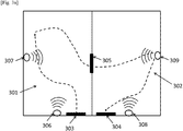
- the figures 3a and 3b represent a grouping of sensors according to a possible embodiment of the invention.
- the geographic area includes two sub-areas 301 and 302, which here represent rooms of an apartment.
- a door 303 provides access to the first room 301 and a door 304 provides access to the second room 302.
- a connecting door 305 allows passage from one room to another.
- Each room includes two motion sensors 306, 307 in the first room and 308, 309 in the second room.
- one of the sensors 306, 308 is located at the entrance to the room, next to the door 303, 304.
- the other sensor 307, 309 is located at one end of the room opposite the door communicating 305.
- An example of the path traveled by an individual is shown in broken lines on the figure 3 . It is assumed that the positions of the sensors 306 and 308 are known, and that the positions of the sensors 307 and 309 are unknown.
- the sensor when an individual passes close to a motion sensor 306, 307, 308, 309, the sensor sends to the location device data indicating that it has been activated (“ON” notification). If the sensor is not reactivated within a predefined time interval (for example 5 seconds), it sends a data indicating to the location device that it has not been reactivated (“OFF” notification).
- a sensor whose location is known as a reference sensor, for example the sensor 306.
- Each datum (“ON” or "OFF” notification) can be associated with a respective time (time transmission time, reception time by the localization device, etc.).
- a notification sent by the reference sensor 306 is associated with a time, taken as the reference time. Each time a notification is received, the difference between the time associated with the sensor from which the notification originates and the reference time is calculated. The differences can be used to determine the locations of sensors 307, 309 whose location is unknown.
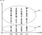
- the temporal differences can be placed on a graph according to the different modalities of the variable considered (here "ON / OFF", or "1/0") and the partitioning algorithm can be used.
- the result of applying the partitioning algorithm is shown on the figure 3b by ellipses 311, 312 in broken lines.
- Data corresponding to sensor 307 located in the same room 301 as the sensor 306 are represented by circles ( ⁇ )
- the data corresponding to the sensors 308, 309 located in the other room 302 are respectively represented by squares ( ⁇ ) and triangles ( ⁇ ).
- the four vertical lines represent the four possible combinations i / j of notifications (“1/0” for “ON / OFF”) where i is the notification corresponding to the reference sensor 306 and j is the notification corresponding to another sensor 307, 308, 309.
- i is the notification corresponding to the reference sensor 306
- j is the notification corresponding to another sensor 307, 308, 309.
- the partitioning algorithm also grouped the other sensors 308, 309 into the same group 311, without being able to distinguish the two sensors 308 and 309.
- the sensor 307 can then be associated with the sub-area 301 (that is to say say that of the reference sensor 306, which is known to belong to the sub-zone 301), and the sensor 309, which belongs to the same group as the sensor 308, can then be associated with the sub-zone 302 (c 'that is to say that of the sensor 308, which is known to belong to the sub-zone 302).
- the figure 4 shows an example of a device for locating a sensor in an embodiment of the invention.
- the device 400 includes a memory 405 for storing instructions allowing the implementation of the method, the measurement data received, and temporary data for carrying out the different steps of the method as described above.
- SOCs or system on a chip are embedded systems which integrate all the components of an electronic system into a single chip.
- An ASIC is a specialized electronic circuit which brings together functionalities tailored to a given application.
- ASICs are generally configured during their manufacture and can only be simulated by the user.
- FPGA Field-Programmable Gate Array
- This device comprises an input interface 403 for the reception of data from the sensors, and an output interface 406 for the supply of control signals controlling an external device 407.
- the device can include, to allow easy interaction with a user, a screen 401 and a keyboard 402.
- the keyboard is optional, in particular when the device corresponds to a computer having the shape of a touch pad, for example.
- the device 400 can be a computer, a network of computers, an electronic component, or another device comprising a processor operatively coupled to a memory, as well as, depending on the embodiment chosen, a data storage unit, and other associated hardware such as a network interface and a media drive for reading from and writing to removable storage media (not shown in the figure).
- the removable storage medium can be, for example, a compact disc (CD), a digital video / multi-purpose disc (DVD), a flash disc, a USB stick, etc.
- the memory, the data storage unit or the removable storage medium contains instructions which, when executed by the control circuit 404, cause this control circuit 404 to carry out or control the input interface 403, output interface 406, storage of data in memory 405 and / or data processing of the examples of implementation of the proposed method described herein.
- the control circuit 404 can be a component implementing the control of the units 403, 405 and 406 of the device 400.
- the device 400 can be implemented in software form, in which case it takes the form of a program executable by a processor, or in hardware form (or “hardware"), such as an application-specific integrated circuit (ASIC). , a system on chip (SOC), or in the form of a combination of hardware and software elements, such as for example a software program intended to be loaded and executed on an electronic component described above (eg FPGA, processor) .
- ASIC application-specific integrated circuit
- SOC system on chip
- FPGA field-programmable gate array
- the device 400 can also use hybrid architectures, such as for example architectures based on a CPU + FPGA, a GPU (Graphics Processing Unit) or an MPPA (Multi-Purpose Processor Array).
- hybrid architectures such as for example architectures based on a CPU + FPGA, a GPU (Graphics Processing Unit) or an MPPA (Multi-Purpose Processor Array).
- the functional diagram presented on the figure 2 is a typical example of a program of which certain instructions can be carried out with the device described. As such, the figure 2 may correspond to the flowchart of the general algorithm of a computer program within the meaning of the invention.
Landscapes
- Engineering & Computer Science (AREA)
- Databases & Information Systems (AREA)
- Theoretical Computer Science (AREA)
- General Engineering & Computer Science (AREA)
- Physics & Mathematics (AREA)
- General Physics & Mathematics (AREA)
- Data Mining & Analysis (AREA)
- Remote Sensing (AREA)
- Automation & Control Theory (AREA)
- Telephonic Communication Services (AREA)
- Mobile Radio Communication Systems (AREA)
Applications Claiming Priority (1)
| Application Number | Priority Date | Filing Date | Title |
|---|---|---|---|
| FR1873114A FR3090127A1 (fr) | 2018-12-17 | 2018-12-17 | Procédé de localisation de capteurs |
Publications (1)
| Publication Number | Publication Date |
|---|---|
| EP3671376A1 true EP3671376A1 (de) | 2020-06-24 |
Family
ID=66530235
Family Applications (1)
| Application Number | Title | Priority Date | Filing Date |
|---|---|---|---|
| EP19216145.3A Pending EP3671376A1 (de) | 2018-12-17 | 2019-12-13 | Sensoren-lokalisierungsverfahren |
Country Status (3)
| Country | Link |
|---|---|
| US (1) | US11442968B2 (de) |
| EP (1) | EP3671376A1 (de) |
| FR (1) | FR3090127A1 (de) |
Families Citing this family (2)
| Publication number | Priority date | Publication date | Assignee | Title |
|---|---|---|---|---|
| WO2022172450A1 (ja) * | 2021-02-15 | 2022-08-18 | 日本電信電話株式会社 | データ収集装置、データ収集方法およびデータ収集プログラム |
| KR20240018290A (ko) * | 2022-08-02 | 2024-02-13 | 삼성전자주식회사 | 알림을 제공하기 위한 방법 및 이를 지원하는 전자 장치 |
Citations (2)
| Publication number | Priority date | Publication date | Assignee | Title |
|---|---|---|---|---|
| US6529164B1 (en) | 2000-03-31 | 2003-03-04 | Ge Medical Systems Information Technologies, Inc. | Object location monitoring within buildings |
| US20120086568A1 (en) * | 2010-10-06 | 2012-04-12 | Microsoft Corporation | Inferring Building Metadata From Distributed Sensors |
Family Cites Families (3)
| Publication number | Priority date | Publication date | Assignee | Title |
|---|---|---|---|---|
| US7904209B2 (en) * | 2007-03-01 | 2011-03-08 | Syracuse University | Open web services-based indoor climate control system |
| US9142114B2 (en) * | 2013-01-28 | 2015-09-22 | Apple Inc. | Tracking group members' proximity |
| JP6242930B2 (ja) * | 2016-03-17 | 2017-12-06 | 株式会社東芝 | センサデータ管理装置、センサデータ管理方法およびプログラム |
-
2018
- 2018-12-17 FR FR1873114A patent/FR3090127A1/fr not_active Withdrawn
-
2019
- 2019-12-13 EP EP19216145.3A patent/EP3671376A1/de active Pending
- 2019-12-16 US US16/715,619 patent/US11442968B2/en active Active
Patent Citations (2)
| Publication number | Priority date | Publication date | Assignee | Title |
|---|---|---|---|---|
| US6529164B1 (en) | 2000-03-31 | 2003-03-04 | Ge Medical Systems Information Technologies, Inc. | Object location monitoring within buildings |
| US20120086568A1 (en) * | 2010-10-06 | 2012-04-12 | Microsoft Corporation | Inferring Building Metadata From Distributed Sensors |
Non-Patent Citations (2)
| Title |
|---|
| CRUL STIJN ET AL: "Improved commissioning in indoor wireless networks through sensor fusion using clustering", 2018 IEEE SENSORS APPLICATIONS SYMPOSIUM (SAS), IEEE, 12 March 2018 (2018-03-12), pages 1 - 6, XP033345780, DOI: 10.1109/SAS.2018.8336780 * |
| GAUGER M ET AL: "Sensor-Based Clustering for Indoor Applications", SENSOR, MESH AND AD HOC COMMUNICATIONS AND NETWORKS, 2008. SECON '08. 5TH ANNUAL IEEE COMMUNICATIONS SOCIETY CONFERENCE ON, IEEE, PISCATAWAY, NJ, USA, 16 June 2008 (2008-06-16), pages 478 - 486, XP031282624, ISBN: 978-1-4244-1777-3 * |
Also Published As
| Publication number | Publication date |
|---|---|
| US20200192919A1 (en) | 2020-06-18 |
| FR3090127A1 (fr) | 2020-06-19 |
| US11442968B2 (en) | 2022-09-13 |
Similar Documents
| Publication | Publication Date | Title |
|---|---|---|
| US8744749B2 (en) | Radio model updating | |
| KR101609296B1 (ko) | 지오펜스 모니터링을 위한 무선 액세스 포인트의 선택 | |
| CN104813185B (zh) | 使用状态空间估计器进行位置确定 | |
| EP3588912A1 (de) | Vorrichtung und verfahren zur gemeinsamen nutzung von kontextinformationen | |
| US10979854B2 (en) | Extending a radio map | |
| US9291698B2 (en) | Wireless communication device, wireless communication method, and computer program product | |
| WO2013154679A1 (en) | Personalized position determination using information correlation and self- sourcing | |
| CN104813186A (zh) | 使用指纹数据进行位置确定 | |
| Dong et al. | Sensing and data acquisition | |
| WO2017079360A1 (en) | Systems and methods for controlling devices | |
| Campana et al. | Towards an indoor navigation system using Bluetooth Low Energy Beacons | |
| Ould-Ahmed-Vall et al. | Distributed fault-tolerance for event detection using heterogeneous wireless sensor networks | |
| EP3671376A1 (de) | Sensoren-lokalisierungsverfahren | |
| Haute et al. | Comparability of RF-based indoor localisation solutions in heterogeneous environments: an experimental study | |
| KR20230174610A (ko) | 위치 측위 방법 및 장치 | |
| US11089666B1 (en) | Room type determinations with motion sensors | |
| Ristimella | Smart luminaire positioning and lighting control in collaborative spaces | |
| US20260059323A1 (en) | Systems and methods for network policy and parental controls based on spatial awareness | |
| FR3067483A1 (fr) | Procede de detection de presence d'individus | |
| EP3807736A1 (de) | Abbildung und gleichzeitige lokalisierung eines objektes in einer innenumgebung | |
| KR102278103B1 (ko) | 전동 커튼 제어 시스템 | |
| EP2080034B1 (de) | Einrichtung zum lokalisieren und/oder identifizieren von gütern und/oder personen in einem beliebigen raum | |
| WO2025214874A1 (en) | Configuring an rf-based sensing system | |
| Qiu | Improving Indoor Positioning Via Mobile Sensing | |
| Teixeira | Time management through indoor location |
Legal Events
| Date | Code | Title | Description |
|---|---|---|---|
| PUAI | Public reference made under article 153(3) epc to a published international application that has entered the european phase |
Free format text: ORIGINAL CODE: 0009012 |
|
| STAA | Information on the status of an ep patent application or granted ep patent |
Free format text: STATUS: THE APPLICATION HAS BEEN PUBLISHED |
|
| AK | Designated contracting states |
Kind code of ref document: A1 Designated state(s): AL AT BE BG CH CY CZ DE DK EE ES FI FR GB GR HR HU IE IS IT LI LT LU LV MC MK MT NL NO PL PT RO RS SE SI SK SM TR |
|
| AX | Request for extension of the european patent |
Extension state: BA ME |
|
| RAP1 | Party data changed (applicant data changed or rights of an application transferred) |
Owner name: ORANGE |
|
| STAA | Information on the status of an ep patent application or granted ep patent |
Free format text: STATUS: REQUEST FOR EXAMINATION WAS MADE |
|
| 17P | Request for examination filed |
Effective date: 20201207 |
|
| RBV | Designated contracting states (corrected) |
Designated state(s): AL AT BE BG CH CY CZ DE DK EE ES FI FR GB GR HR HU IE IS IT LI LT LU LV MC MK MT NL NO PL PT RO RS SE SI SK SM TR |
|
| RAP3 | Party data changed (applicant data changed or rights of an application transferred) |
Owner name: ORANGE |
|
| STAA | Information on the status of an ep patent application or granted ep patent |
Free format text: STATUS: EXAMINATION IS IN PROGRESS |
|
| 17Q | First examination report despatched |
Effective date: 20221017 |