EP3671390B1 - Verfahren zum betrieb eines unbemannten luftfahrzeugs sowie ein unbemanntes luftfahrzeug - Google Patents
Verfahren zum betrieb eines unbemannten luftfahrzeugs sowie ein unbemanntes luftfahrzeug Download PDFInfo
- Publication number
- EP3671390B1 EP3671390B1 EP18215039.1A EP18215039A EP3671390B1 EP 3671390 B1 EP3671390 B1 EP 3671390B1 EP 18215039 A EP18215039 A EP 18215039A EP 3671390 B1 EP3671390 B1 EP 3671390B1
- Authority
- EP
- European Patent Office
- Prior art keywords
- trajectory
- aerial vehicle
- unmanned aerial
- flight
- communication link
- Prior art date
- Legal status (The legal status is an assumption and is not a legal conclusion. Google has not performed a legal analysis and makes no representation as to the accuracy of the status listed.)
- Active
Links
Images


Classifications
-
- G—PHYSICS
- G05—CONTROLLING; REGULATING
- G05D—SYSTEMS FOR CONTROLLING OR REGULATING NON-ELECTRIC VARIABLES
- G05D1/00—Control of position, course, altitude or attitude of land, water, air or space vehicles, e.g. using automatic pilots
- G05D1/0005—Control of position, course, altitude or attitude of land, water, air or space vehicles, e.g. using automatic pilots with arrangements to save energy
-
- G—PHYSICS
- G05—CONTROLLING; REGULATING
- G05D—SYSTEMS FOR CONTROLLING OR REGULATING NON-ELECTRIC VARIABLES
- G05D1/00—Control of position, course, altitude or attitude of land, water, air or space vehicles, e.g. using automatic pilots
- G05D1/0011—Control of position, course, altitude or attitude of land, water, air or space vehicles, e.g. using automatic pilots associated with a remote control arrangement
- G05D1/0022—Control of position, course, altitude or attitude of land, water, air or space vehicles, e.g. using automatic pilots associated with a remote control arrangement characterised by the communication link
-
- G—PHYSICS
- G05—CONTROLLING; REGULATING
- G05D—SYSTEMS FOR CONTROLLING OR REGULATING NON-ELECTRIC VARIABLES
- G05D1/00—Control of position, course, altitude or attitude of land, water, air or space vehicles, e.g. using automatic pilots
- G05D1/10—Simultaneous control of position or course in three dimensions
- G05D1/101—Simultaneous control of position or course in three dimensions specially adapted for aircraft
- G05D1/106—Change initiated in response to external conditions, e.g. avoidance of elevated terrain or of no-fly zones
-
- G—PHYSICS
- G08—SIGNALLING
- G08C—TRANSMISSION SYSTEMS FOR MEASURED VALUES, CONTROL OR SIMILAR SIGNALS
- G08C17/00—Arrangements for transmitting signals characterised by the use of a wireless electrical link
-
- G—PHYSICS
- G08—SIGNALLING
- G08G—TRAFFIC CONTROL SYSTEMS
- G08G5/00—Traffic control systems for aircraft
- G08G5/20—Arrangements for acquiring, generating, sharing or displaying traffic information
- G08G5/26—Transmission of traffic-related information between aircraft and ground stations
-
- G—PHYSICS
- G08—SIGNALLING
- G08G—TRAFFIC CONTROL SYSTEMS
- G08G5/00—Traffic control systems for aircraft
- G08G5/30—Flight plan management
- G08G5/32—Flight plan management for flight plan preparation
-
- G—PHYSICS
- G08—SIGNALLING
- G08G—TRAFFIC CONTROL SYSTEMS
- G08G5/00—Traffic control systems for aircraft
- G08G5/30—Flight plan management
- G08G5/34—Flight plan management for flight plan modification
-
- G—PHYSICS
- G08—SIGNALLING
- G08G—TRAFFIC CONTROL SYSTEMS
- G08G5/00—Traffic control systems for aircraft
- G08G5/50—Navigation or guidance aids
- G08G5/55—Navigation or guidance aids for a single aircraft
-
- G—PHYSICS
- G08—SIGNALLING
- G08G—TRAFFIC CONTROL SYSTEMS
- G08G5/00—Traffic control systems for aircraft
- G08G5/70—Arrangements for monitoring traffic-related situations or conditions
- G08G5/74—Arrangements for monitoring traffic-related situations or conditions for monitoring terrain
-
- H—ELECTRICITY
- H04—ELECTRIC COMMUNICATION TECHNIQUE
- H04W—WIRELESS COMMUNICATION NETWORKS
- H04W4/00—Services specially adapted for wireless communication networks; Facilities therefor
- H04W4/02—Services making use of location information
- H04W4/023—Services making use of location information using mutual or relative location information between multiple location based services [LBS] targets or of distance thresholds
-
- H—ELECTRICITY
- H04—ELECTRIC COMMUNICATION TECHNIQUE
- H04W—WIRELESS COMMUNICATION NETWORKS
- H04W4/00—Services specially adapted for wireless communication networks; Facilities therefor
- H04W4/30—Services specially adapted for particular environments, situations or purposes
- H04W4/40—Services specially adapted for particular environments, situations or purposes for vehicles, e.g. vehicle-to-pedestrians [V2P]
-
- B—PERFORMING OPERATIONS; TRANSPORTING
- B64—AIRCRAFT; AVIATION; COSMONAUTICS
- B64U—UNMANNED AERIAL VEHICLES [UAV]; EQUIPMENT THEREFOR
- B64U10/00—Type of UAV
- B64U10/25—Fixed-wing aircraft
-
- B—PERFORMING OPERATIONS; TRANSPORTING
- B64—AIRCRAFT; AVIATION; COSMONAUTICS
- B64U—UNMANNED AERIAL VEHICLES [UAV]; EQUIPMENT THEREFOR
- B64U2201/00—UAVs characterised by their flight controls
- B64U2201/10—UAVs characterised by their flight controls autonomous, i.e. by navigating independently from ground or air stations, e.g. by using inertial navigation systems [INS]
-
- B—PERFORMING OPERATIONS; TRANSPORTING
- B64—AIRCRAFT; AVIATION; COSMONAUTICS
- B64U—UNMANNED AERIAL VEHICLES [UAV]; EQUIPMENT THEREFOR
- B64U2201/00—UAVs characterised by their flight controls
- B64U2201/20—Remote controls
-
- G—PHYSICS
- G08—SIGNALLING
- G08G—TRAFFIC CONTROL SYSTEMS
- G08G5/00—Traffic control systems for aircraft
- G08G5/50—Navigation or guidance aids
- G08G5/57—Navigation or guidance aids for unmanned aircraft
Definitions
- the invention relates to a method for operating an unmanned aerial vehicle.
- the invention further relates to an unmanned aerial vehicle.
- Missions for unmanned aerial vehicles are often planned by taking into consideration a fuel consumption, a mission performance and a probability of mission success. After performing such a planned mission, a UAV returns to its home position. This method is optimal when route by route can be assessed before the mission, or when the number of missions is kept relatively low. However, during the mission the quality of a communication link between the UAV and a ground station may at least in some sections be reduced or insufficient.
- US 2018/0017973 A1 discloses a method of navigating a drone under consideration of WWAN radio link quality. Therefore, this document describes the determination of an initial set route that frequently provides at least a minimum level of WWAN connectivity (e.g. Radio Link Quality Level 1 and 2). According to this document, this determined set route is provided to the UAV (Fig. 8, step 820). This document further describes that during flight the radio link quality is measured and in case the quality drops below a certain threshold, a search maneuver is assigned for use by the drone to improve the radio link quality.
- a minimum level of WWAN connectivity e.g. Radio Link Quality Level 1 and 2
- the object of the invention therefore lies in operating an unmanned aerial vehicle in a way that the quality of the communication link can be maintained throughout a flight mission.
- It is proposed a method for operating an unmanned aerial vehicle comprising the steps of defining at least one initial waypoint for creating an initial trajectory, receiving geographic information along the trajectory, conducting a numerical simulation of a communication link between the unmanned aerial vehicle along the trajectory and at least one predetermined ground station at a predetermined ground station position, which comprises calculating a quality factor for the communication link under consideration of the geographic information, and comparing the quality factors with at least one predetermined minimum quality factor, and in case of an insufficient quality factor on the trajectory, adjusting the position of at least one waypoint to form an adjusted trajectory, and repeating the numerical simulation of the communication link until the quality factors along the adjusted trajectory reach at least the minimum quality factor, to form an optimized final trajectory.
- a method for operating a UAV which significantly differs from known methods.
- the proposed method defines an iteration process for optimizing a trajectory of an unmanned aerial vehicle.
- it is also taken into account to improving the connectivity between the UAV and a ground station.
- an urban environment where the vehicle will be operated, is challenging due to a heterogenous structure with different coexisting topologies.
- the signal quality faces effects such as multipath, Doppler shift and shadowing.
- the signal may degrade to the point that reception is no longer possible.
- techniques such as modulation schemes and different waveforms are applied to tackle distortion of the signal. Nevertheless, this has been a suitable solution for static environments where conditions are predefined and standard.
- a novel technique to enhance connectivity through the flight will be proposed. The main objective is to maintain the quality of connection through the trajectory to avoid disruption of the signal.
- At first, at least one waypoint may be defined for creating the initial trajectory.
- the initial trajectory may be a straight line from a starting point to the target.
- this initial trajectory may be provided to a flight control unit or another computer unit to allow the UAV to follow the trajectory directly before conducting the signal quality driven optimization.
- the optimization may then be conducted during the flight.
- the optimization is conducted once, to allow the UAV to start with an already optimized trajectory and then continuously re-optimize the trajectory during flight.
- a re-optimization is conducted throughout the flight as well. If the situation is that the airspace is populated e.g. with autonomous flying objects with different applications such as flying taxis, cars, medical transport or parcel transport, a fix planning of each route or trajectory may not be feasible.
- the quality of the link may be considered throughout the flight and the trajectory is adapted to have the best connection at any given time. This means, that a trajectory may constantly be adjusted to maintain a desired signal quality.
- the connection quality during the flight is simulated. If it turns out that the connection quality is not as desired at any section of the trajectory, the trajectory is changed and the simulation is conducted again. This is repeated, i.e. the signal quality over the changed trajectory is simulated again, until it meets the requirements.
- the method comprises an optimization loop for optimizing a trajectory for a UAV that takes account of the signal quality.
- receiving geographical information may be an important step in the process of simulating the signal quality.
- receiving geographical information may comprise receiving terrain information and an elevation profile from a data source through respective queries.
- the data source may be a publicly available data source or a private data source.
- the geographic information may be collected at a plurality of positions along the trajectory. These positions may be represented by a plurality of distanced points distributed along the trajectory.
- the number of these may be increased or decreased depending on the desired accuracy for the geographic information. It is also feasible to gather geographic information that are lateral thereto. Hence, for example the geographic information along a stripe-shaped area underneath the trajectory may be considered. The relevant amount of information may be chosen according to flight altitude or other parameters.
- the simulation may be conducted by an algorithm that is capable of calculating a signal transfer between the UAV and the at least one ground station.
- the precision of the simulation can be increased with increasing the number of considered increments or incremental positions along the trajectory for the individual simulation calculations as well as the level of detail of the simulation.
- a precise simulation of the communication link enables to determine a quality factor for the communication link, which allows to evaluate, whether the signal quality or data transfer quality is sufficient.
- the quality factor along the trajectory should equal at least the minimum quality factor.
- the respective quality factors may be compared to the minimum quality factor. In case of an occurrence of a quality factor that is too low the shape of the trajectory is adjusted and the whole simulation is conducted again. This is repeated until the quality factors along the trajectory all meet the requirement of the minimum quality factor.
- Adjusting the shape of the trajectory may refer to a variety of possible options.
- the trajectory may be adjusted by changing the course to greater or lower altitudes or to introduce a certain curvature that allows to improve the signal quality, e.g. by reducing shadowing, reflection or absorption effects.
- the method according to the invention allows to influence the flight of a UAV by adjusting the trajectory to improve the quality of a communication link.
- a preferred embodiment further comprises the step of a numerical simulation of a flight of the unmanned aerial vehicle along the trajectory, wherein the calculating of the quality factor is conducted under consideration of simulated flight states along the trajectory.
- flight states along the trajectory can be determined. These include attitude information, such as roll, pitch and yaw, as well as heading information and thrust.
- attitude information such as roll, pitch and yaw
- heading information and thrust the position and orientation of the antenna or the antennas of the UAV can be determined for a plurality of positions along the trajectory with a certain desired precision. Based on the precise spatial orientation and position of the antenna, the simulation of the communication link can be conducted with a higher precision along these respective positions along the trajectory.
- the numerical simulation is also repeated before repeating the numerical simulation of the communication link.
- the precise antenna positions can be determined.
- the unmanned aerial vehicle may be flight-controlled by a flight control unit to follow a given trajectory, wherein the method further comprises providing the final trajectory to the flight control unit.
- the flight control unit in the UAV can continue the flight with the adjusted trajectory.
- conducting the numerical simulation of the flight comprises executing a dynamic model of the UAV and the flight control unit to control the dynamic model of the UAV to follow the given trajectory.
- the dynamic model of the UAV may comprise a set of equations, that are capable of defining the dynamic behavior of the UAV during flight. This also comprises a description of the aerodynamic behavior.
- the dynamic model may be a simplified, linear model or a more sophisticated, nonlinear model.
- the actual simulation may be conducted with a fixed time step or a dynamically adjusted time step.
- the simulation may also comprise a simulation of the flight control unit, which is responsible for moving control surfaces of the UAV, for adjusting the engine thrust and for receiving and processing sensor information.
- the combination of the flight control unit and the dynamic UAV model leads to a precise statement of the attitude and heading, which influence the momentary position of on board antennas used for the communication link. It may be feasible to linearize the dynamic model and to maintain a minimum time step value for the simulation to avoid unpredictable discontinuities in the model, which may lead to continuously reducing the time step values and thus block the simulation.
- receiving geographic information comprises retrieving terrain characteristics and elevation information along the trajectory.
- Elevation information may comprise data that define the elevation of the ground relative to sea level. It is to be understood that the elevations of a ground area underneath a line of sight between the UAV and the ground station may influence the signal propagation characteristics. Particularly in an urban environment, the elevation may be rather diverse over a certain area. Thus, it may be preferred to take elevation information into account, that are associated with an area from underneath the UAV to a desired target. Further, terrain characteristics may also clearly influence the signal propagation due to differing reflection and absorption conditions. It may be feasible to retrieve information about the terrain being covered by roads, by water, by vegetation, whether they are bare ground or city ground. For example, water may clearly influence the reflection. By combining the information of elevation information and terrain characteristics it may be possible to gain knowledge of the altitude of reflected rays.
- conducting the numerical simulation of the communication link comprises executing a deterministic channel model for a signal propagation depending on the geographic information and UAV-related boundary conditions.
- the deterministic channel model for the signal propagation allows to clearly determine the quality of the communication link.
- the shadowing caused by the UAV structure needs to be analyzed.
- structural elements such as wings may interpose between an antenna of the UAV and the ground station. Since these usually only have a little transparency to radio signals, they may reduce the quality of the communication link.
- a geometric model of the UAV may be added to the channel model.
- a simplified geometric model may be used to describe the UAV frame with a lean and efficient number of structural nodes to achieve a desired accuracy.
- the installation position of the antenna(s) is to be included into the channel model to take obscuration effects into account.
- the size and beam characteristics or radiation pattern of the antenna(s) used for the communication link may be defined to include this information into the respective channel calculation. While the radiation pattern of the antenna may be calculated with a basic or usual characteristic of a respective type of antenna, it may be worthwhile to rely on a radiation pattern provided by the manufacturer of the antenna.
- Radio channel models for narrowband and wideband transmissions are commonly used to predict coverage of a wireless link and system performance. These methods are classified as deterministic, statistical/empirical and semi-deterministic or site specific models.
- deterministic models have been employed with ray tracing techniques. Ray tracing takes into account free space loss, reflected and refracted components as well as diffracted and scattered contributions to the line of sight component. It may be feasible to choose the narrowband single input-single output model as the channel model.
- the first fraction models the reflection that depends on the terrain characteristics
- ⁇ r1 being the relative permittivity of the propagation media
- ⁇ r2 being the permittivity of the terrain.
- the second part of the amplitude models the rugosity of the terrain, with ⁇ h representing the standard deviation of the rugosity and ⁇ i the angle of incidence of the ray on the surface of the terrain.
- This channel model constitutes a deterministic model. Information about the position of the UAV and ground or receiving station as well as site characteristics must be known in order to determine the characteristics of the wireless channel. The parameters marked in the frequency offset equation that refer to the position of the transmitter require the availability of information about the position and velocity of the UAV at every point.
- the boundary conditions related to the unmanned aerial vehicle may exemplarily comprise a shape and a material of the unmanned aerial vehicle, as well as the installation position and orientation of at least one antenna on the unmanned aerial vehicle that is associated with the communication link.
- the step of adjusting the position of at least one waypoint to form an adjusted trajectory comprises a Pareto optimization, a particle swarm optimization or an optimization based on evolutionary algorithms.
- the variable to optimize is the overall connection quality through the trajectory.
- the optimization algorithm may tend to go towards the trajectory with the highest received gain. With this optimization goal, zones with unfavorable channel conditions are avoided.
- One of the possible algorithms is a Pareto optimization algorithm, which is also known as a multi-objective optimization, which involves multiple objective functions. It may be realized in the form of the so-called goal-attainment algorithm. It may be used if several objective functions, such as the trajectory length and the risk of signal loss, are considered at the same time.
- the objectives are combined in different manners performing several uni-objective optimizations.
- Each one of these optimizations provides a possible solution, which is referred to as a Pareto optimal solution, and all these solutions conform the so-called Pareto front.
- Pareto front Once the Pareto front is obtained, a proper assessment of the gain in one objective when relaxing the other can be made, and the most convenient point of the Pareto front can be selected.
- the goal-attainment algorithm can be used to determine the Pareto front, and another algorithm is needed to select the most convenient solution of the Pareto front, in view of the full set of solutions of that the front finally offers.
- the further optimization i.e. the particle swarm optimization, is based on the study of species like bees, birds or a flock of other animals. It represents a stylized flock of animals, such as bees, who explore their complete environment in order to find the best resources, at the same time the other bees will know where a bee has already been.
- These algorithms are extremely flexible, can be combined with other algorithms and require a low knowledge of the surroundings. Of course, further algorithms may be possible.
- the step of adjusting the position of at least one waypoint to form an adjusted trajectory comprises applying at least one geometry constraint in the adjusted trajectory.
- an iterative algorithm is responsible for the final trajectory of the unmanned aerial vehicle, but also some geometry constraints. These may limit the extension or orientation of the trajectory based on predefined restrictions. These may inter alia include zones, into which the unmanned aerial vehicle must not fly.
- the at least one geometry constraint is selected from a group of geometry constraints, the group consisting of maintaining a certain altitude above the terrain, providing a minimum distance to buildings on the ground for collision avoidance, restricting the adjusted trajectory to given map limits, avoiding flight prohibited zones, and maintaining a safety distance to surrounding aircraft.
- defining at least one initial waypoint for creating the initial trajectory comprises defining a set of initial waypoints for a desired flight mission.
- the initial trajectory, from which an optimized trajectory is created is not necessarily a straight path between a starting point and a desired target. It may also be a curved line, that may belong to a certain surveillance mission, wherein the predefined trajectory may be fine-tuned under taking into account the communication link quality, such that e.g. the bank angles or other manoeuvres are adjusted to maintain the desired communication link quality.
- the quality of the communication link may be considered very important since in a case of an emergency or an undesired condition of the unmanned aerial vehicle, backup or emergency procedures need to be established. One of them may include pass the control to a remote pilot that will guide or monitor the vehicle. In such a case a flaw in the communication link is to be prevented. Since boundary conditions may change during flight, it is particularly advantageous to repeatedly conduct the simulation and, consequently, the optimization of the communication link.
- the simulation is conducted inside the unmanned aerial vehicle.
- This may particularly focus on the flight control unit or a superordinate computer unit, such as a flight management unit, which is able to provide high-level information to the flight control unit, such as the trajectory, which is to be followed by the unmanned aerial vehicle through lower-level control operations of the flight control unit.
- a superordinate computer unit such as a flight management unit
- the simulation is less dependent on an exterior system. This may be beneficial since the unmanned aerial vehicle may always be able to assume a trajectory which leads to a good quality of the communication link.
- the invention further relates to an unmanned aerial vehicle, comprising a computer unit, wherein the computer unit is capable of conducting the above identified method.
- the computer unit is a flight control unit.
- Fig. 1 shows an abstract illustration of a method 2 for operating an unmanned aerial vehicle.
- the method 2 is exemplarily shown in the form of different functional layers that compose the method 2.
- At least one waypoint 4 is defined 6 for creating an initial trajectory.
- This may also include the definition of a plurality of waypoints 4, that may refer to a more sophisticated initial trajectory.
- simply a single target point for a certain flight mission may be defined as an initial waypoint 4 in order to let the method 2 adjust the resulting simple initial trajectory to meet the requirements.
- This step is named layer 1: initialization.
- a numerical simulation 8 of a flight of the unmanned aerial vehicle along the trajectory is conducted.
- the respective layer is named layer 2: aircraft characterization.
- a dynamic UAV model 10 is executed on a computer unit, wherein the dynamic UAV model 10 is capable of characterizing the mechanical and aerodynamic behavior of the unmanned aerial vehicle.
- This may also include executing a dynamic model of a flight control unit, which is dedicated for controlling the unmanned aerial vehicle.
- the dynamic model of the flight control unit may be integrated into the dynamic UAV model 10, as it is responsible for controlling the dynamic UAV model 10 in the simulation 8 to follow the given trajectory.
- a further step is directed to a plurality of tasks of data collection 12, which are summarized in form of layer 3: channel parameters. For example, geographic information for a plurality of positions along the trajectory are received 14. Further, a number of state variables from the dynamic UAV model 10 is collected 16. This may lead to a vector of state variables at a single point in time or to a matrix having state variables over several points in time, e.g. during the whole flight along the trajectory or a section thereof. Further, shape information 18 to describe the geometric shape of the UAV as well as antenna specific information 20 are provided, for example by a set of data stored in the computer unit that conducts the simulation 8. These antenna-specific information 20 may be provided in the form of a static set of data.
- All data from the data collection step 12 are fed into a simulation 22 of the communication link between the unmanned aerial vehicle and a predetermined ground station position.
- a deterministic channel model 24 is created, that allows to calculate a quality factor for the communication link on the consideration of the geographic information, the state variables 16, the shape information 18 as well as the antenna specific information 20. If there is an insufficient quality factor on the trajectory, an optimization step 28 is conducted to form adjusted waypoints 30, which are then fed back into the simulation 8. Thus, as a result, an optimized trajectory may be found that leads to a minimum quality factor und thus, a sufficient quality of the communication link.
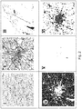
- Fig. 2 shows an example of different geographic information that may be derived from publicly available sources during the step 14 of receiving geographic information. These are shown in six maps I to VI. Map I illustrates a common map with marked places, overlaid elevation-dependent shadings and ground-dependent shadings. Map II shows the coverage of map I by roads. Map III shows the map coverage by water. Map IV is directed to the coverage by vegetation. In map V the coverage by bare ground is depicted and map VI shows the coverage by city ground. All these different information are fed into the deterministic channel model 24 in fig. 1 to calculate potential reflection and absorption effects of radio waves sent out or received by antennas of the UAV.
- a starting point 32 for the UAV is shown, as well as an initial waypoint 34 in the form of a desired target for the UAV.
- an exemplary no-fly-zone 36 is avoided.
- new waypoints 38a, 38b and 38c are generated. It is conceivable that several loops of the method 2 are required to create these.
- an optimized trajectory 40 is provided, which is clearly situated outside the no-fly-zone 36 and allows a good signal quality.
- Fig. 4 shows a very schematic, simplified illustration of an unmanned aerial vehicle 42, which is in flight. It comprises an antenna 44 for communicating with a ground station 46. Furthermore, for following a trajectory, e.g. the trajectory 40 from fig. 3 , the unmanned aerial vehicle 42 comprises a computer unit in the form of a flight control unit 48. As stated above, the flight control unit 48 may be capable of conducting the method to according to the invention. However, also another, dedicated computer unit may be integrated on board the UAV 42 for conducting the method 2. Thus, a communication link 50 between the UAV 42 and the ground station 46 maintains a sufficient connection quality.
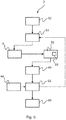
- figure 5 shows the method 2 according to the invention in a block-oriented diagram.
- the method 2 starts with defining 52 at least one initial waypoint 4 for creating the initial trajectory 39.
- geographic information 14 for a plurality of positions along the trajectory are received 54.
- the numerical simulation 8 of a flight of the unmanned aerial vehicle 42 along the trajectory 39 and a simulation 56 of the communication link 50 along a plurality of considered positions along the trajectory 39 and a ground station position of the ground station 46 is conducted.
- This comprises calculating 58 a quality factor for the communication link 50 under consideration of the geographic information 14 and simulated flight state variables 16 in multiple points along the trajectory, and comparing 60 the quality factors with a predetermined minimum quality factor.
- a shape of the trajectory 39 is adjusted 62 to form an adjusted trajectory. This is repeated until the quality factors along the adjusted trajectory reach at least the minimum quality factor, to form an optimized final trajectory 40. This may then be provided 66 to flight control unit 48.
- adjusting 62 the shape of the trajectory 39 may include applying 64 at least one geometry constraint.
Landscapes
- Engineering & Computer Science (AREA)
- Physics & Mathematics (AREA)
- General Physics & Mathematics (AREA)
- Aviation & Aerospace Engineering (AREA)
- Radar, Positioning & Navigation (AREA)
- Remote Sensing (AREA)
- Automation & Control Theory (AREA)
- Computer Networks & Wireless Communication (AREA)
- Signal Processing (AREA)
- Control Of Position, Course, Altitude, Or Attitude Of Moving Bodies (AREA)
Claims (15)
- Verfahren (2) zum Betreiben eines unbemannten Luftfahrzeugs (42), wobei das Verfahren (2) die folgenden Schritte umfasst:- Festlegen (6, 52) mindestens eines anfänglichen Wegpunkts (4) zum Erstellen einer anfänglichen Trajektorie, die dem Luftfahrzeug (42) bereitgestellt wird,- Empfangen (54) einer geografischen Information (14) für eine Mehrzahl von Positionen entlang der Trajektorie,- Durchführen einer numerischen Simulation (56) einer Kommunikationsverbindung (50) zwischen dem unbemannten Luftfahrzeug (42) entlang der Trajektorie und mindestens einer vorbestimmten Bodenstation (46) an einer vorbestimmten Bodenstationsposition, welche Berechnen (58) eines Qualitätsfaktors für die Kommunikationsverbindung (50) unter Berücksichtigung der geografischen Information (14) und Vergleichen (60) der Qualitätsfaktoren mit mindestens einem vorbestimmten Mindestqualitätsfaktor umfasst, und- im Fall eines unzureichenden Qualitätsfaktors auf der Trajektorie, Anpassen der Position mindestens eines Wegpunkts (4, 30, 38), um eine angepasste Trajektorie zu bilden, und Wiederholen der numerischen Simulation (56) der Kommunikationsverbindung (50), bis die Qualitätsfaktoren entlang der angepassten Trajektorie mindestens den Mindestqualitätsfaktor erreichen, um eine optimierte endgültige Trajektorie zu bilden,- dadurch gekennzeichnet, dasseine optimierte endgültige Trajektorie dem Luftfahrzeug (42) vor dem Start bereitgestellt wird und wobei die optimierte endgültige Trajektorie während des Flugs des Luftfahrzeugs (42) fortlaufend neu optimiert wird.
- Verfahren (2) nach Anspruch 1, ferner umfassend den Schritt einer numerischen Simulation (8) eines Flugs des unbemannten Luftfahrzeugs (42) entlang der Trajektorie, wobei das Berechnen (58) des Qualitätsfaktors unter Berücksichtigung von simulierten Flugzuständen entlang der Trajektorie durchgeführt wird.
- Verfahren (2) nach Anspruch 1 oder 2,
wobei das unbemannte Luftfahrzeug (42) durch eine Flugsteuerungseinheit (48) fluggesteuert wird, so dass es einer vorgegebenen Trajektorie folgt, wobei das Verfahren ferner Bereitstellen der endgültigen Trajektorie für die Flugsteuerungseinheit (48) umfasst. - Verfahren (2) nach Anspruch 3,
wobei das Durchführen der numerischen Simulation (8) des Flugs Ausführen eines dynamischen Modells (10) des unbemannten Luftfahrzeugs (42) umfasst und die Flugsteuerungseinheit (48) das dynamische Modell (10) des unbemannten Luftfahrzeugs (42) steuert, so dass es der vorgegebenen Trajektorie folgt. - Verfahren (2) nach einem der vorhergehenden Ansprüche,
wobei das Empfangen (54) einer geografischen Information (14) Abrufen von Geländeeigenschaften und Höheninformation entlang der Trajektorie umfasst. - Verfahren (2) nach einem der vorhergehenden Ansprüche,
wobei das Durchführen der numerischen Simulation (56) der Kommunikationsverbindung (50) Ausführen eines deterministischen Kanalmodells (24) für eine Signalausbreitung abhängig von der geografischen Information (14) und Grenzbedingungen in Bezug auf das unbemannte Luftfahrzeug (42) umfasst. - Verfahren (2) nach Anspruch 6,
wobei die Grenzbedingungen in Bezug auf das unbemannte Luftfahrzeug (42) eine Form und ein Material des unbemannten Luftfahrzeugs (42) sowie die Einbauposition und Ausrichtung mindestens einer Antenne (44) an dem unbemannten Luftfahrzeug (42), die mit der Kommunikationsverbindung (50) assoziiert ist, umfasst. - Verfahren (2) nach einem der vorhergehenden Ansprüche,
wobei der Schritt des Anpassens (62) der Position mindestens eines Wegpunkts, um eine angepasste Trajektorie auszubilden, eine Pareto-Optimierung, eine Partikelschwarm-Optimierung oder eine Optimierung basierend auf evolutionären Algorithmen umfasst. - Verfahren (2) nach einem der vorhergehenden Ansprüche,
wobei der Schritt des Anpassens (62) der Position mindestens eines Wegpunkts, um eine angepasste Trajektorie auszubilden, Anwenden (64) mindestens einer geometrischen Randbedingung in der angepassten Trajektorie umfasst. - Verfahren (2) nach Anspruch 9,
wobei die mindestens eine geometrische Randbedingung ausgewählt ist aus einer Gruppe von geometrischen Randbedingungen, wobei die Gruppe aus Folgendem besteht:- Beibehalten einer gewissen Höhe über dem Gelände,- Bereitstellen eines Mindestabstands zu Gebäuden am Boden zur Kollisionsvermeidung,- Beschränken der angepassten Trajektorie auf vorgegebene Kartengrenzen,- Umgehen von Flugverbotszonen, und- Beibehalten eines Sicherheitsabstands zu umgebenden Luftfahrzeugen. - Verfahren (2) nach einem der vorhergehenden Ansprüche,
wobei das Festlegen (6, 52) mindestens eines anfänglichen Wegpunkts (4) zum Erstellen der anfänglichen Trajektorie Festlegen eines Satzes von anfänglichen Wegpunkten (4) für eine gewünschte Flugmission umfasst. - Verfahren (2) nach einem der vorhergehenden Ansprüche,
wobei die numerische Simulation (56) der Kommunikationsverbindung (50) fortlaufend und wiederholt während des Flugs des unbemannten Luftfahrzeugs (42) durchgeführt wird. - Verfahren (2) nach einem der vorhergehenden Ansprüche,
wobei die numerische Simulation (56) der Kommunikationsverbindung (50) in dem unbemannten Luftfahrzeug (42) durchgeführt wird. - Unbemanntes Luftfahrzeug, umfassend eine Computereinheit (48), wobei die Computereinheit (48) in der Lage ist, das Verfahren (2) nach einem der Ansprüche 1 bis 13 durchzuführen.
- Unbemanntes Luftfahrzeug nach Anspruch 14, wobei die Computereinheit (48) eine Flugsteuerungseinheit (48) ist.
Priority Applications (2)
| Application Number | Priority Date | Filing Date | Title |
|---|---|---|---|
| EP18215039.1A EP3671390B1 (de) | 2018-12-21 | 2018-12-21 | Verfahren zum betrieb eines unbemannten luftfahrzeugs sowie ein unbemanntes luftfahrzeug |
| US16/709,179 US11460840B2 (en) | 2018-12-21 | 2019-12-10 | Method for operating an unmanned aerial vehicle as well as an unmanned aerial vehicle |
Applications Claiming Priority (1)
| Application Number | Priority Date | Filing Date | Title |
|---|---|---|---|
| EP18215039.1A EP3671390B1 (de) | 2018-12-21 | 2018-12-21 | Verfahren zum betrieb eines unbemannten luftfahrzeugs sowie ein unbemanntes luftfahrzeug |
Publications (2)
| Publication Number | Publication Date |
|---|---|
| EP3671390A1 EP3671390A1 (de) | 2020-06-24 |
| EP3671390B1 true EP3671390B1 (de) | 2021-10-13 |
Family
ID=64755359
Family Applications (1)
| Application Number | Title | Priority Date | Filing Date |
|---|---|---|---|
| EP18215039.1A Active EP3671390B1 (de) | 2018-12-21 | 2018-12-21 | Verfahren zum betrieb eines unbemannten luftfahrzeugs sowie ein unbemanntes luftfahrzeug |
Country Status (2)
| Country | Link |
|---|---|
| US (1) | US11460840B2 (de) |
| EP (1) | EP3671390B1 (de) |
Families Citing this family (22)
| Publication number | Priority date | Publication date | Assignee | Title |
|---|---|---|---|---|
| CN106850050A (zh) * | 2016-01-22 | 2017-06-13 | 广州极飞科技有限公司 | 无人机及地面站与无人机的通信系统、方法 |
| US11661186B2 (en) * | 2019-06-10 | 2023-05-30 | Dragonfly Pictures, Inc. | System and method for unmanned aerial signal relay |
| US12488694B2 (en) * | 2019-10-21 | 2025-12-02 | Flylogix Holdings Limited | Flight control systems, ground-based control centres, remotely piloted aircraft, and method |
| US11277203B1 (en) * | 2020-01-22 | 2022-03-15 | Architecture Technology Corporation | Hybrid communications based upon aerial networks |
| US20210287556A1 (en) * | 2020-03-13 | 2021-09-16 | Electronics And Telecommunications Research Institute | Method and apparatus for generating optimal path for an unmanned aerial vehicle |
| CN112616132B (zh) * | 2020-12-16 | 2022-04-01 | 同济大学 | 基于几何先验模型的低空空地无人机信道多径跟踪方法 |
| CN112817337B (zh) * | 2021-04-16 | 2021-08-13 | 北京三快在线科技有限公司 | 获取路径的方法、装置、设备和可读存储介质 |
| CN113377131B (zh) * | 2021-06-23 | 2022-06-03 | 东南大学 | 一种使用强化学习获得无人机收集数据轨迹的方法 |
| CN113596854B (zh) * | 2021-07-21 | 2022-08-09 | 东南大学 | 一种自主移动中继辅助的广域覆盖高速传输方法 |
| CN114257964B (zh) * | 2021-11-29 | 2023-09-26 | 南方电网科学研究院有限责任公司 | 一种电力物联网中继无人机通信方法及装置 |
| CN114371726B (zh) * | 2021-12-06 | 2024-06-07 | 特金智能科技(上海)有限公司 | 无人机空地一体化探测定位方法、装置、系统与设备 |
| US11733372B1 (en) * | 2022-03-28 | 2023-08-22 | Bluehalo, Llc | System and method for dynamic two-way ranging using unmanned aerial vehicles |
| CN115454122B (zh) * | 2022-08-15 | 2024-06-14 | 北京航空航天大学 | 一种高速飞行器追逃微分博弈的邻近凸优化方法 |
| CN115793684B (zh) * | 2022-11-11 | 2025-08-22 | 中国航空工业集团公司西安飞行自动控制研究所 | 一种折叠机翼变体飞机的飞行控制方法及装置 |
| CN116430896B (zh) * | 2023-04-18 | 2025-10-21 | 杭州电子科技大学 | 基于图论与几何的无人机通信轨迹优化方法及系统 |
| CN116500936B (zh) * | 2023-04-24 | 2026-03-17 | 同济大学 | 一种面向无人系统的一体化控制方法、设备、介质 |
| CN116384256B (zh) * | 2023-05-11 | 2023-09-01 | 西安现代控制技术研究所 | 一种基于参考方案局部搜索多约束弹道优化方法 |
| CN116858236B (zh) * | 2023-06-13 | 2026-03-24 | 山东理工大学 | 一种基于衍射原理的无人直升机航线规划方法 |
| CN117316041B (zh) * | 2023-09-18 | 2024-03-26 | 广东电网有限责任公司广州供电局 | 智能机巡专用杆塔标示牌及其控制方法 |
| CN118816896B (zh) * | 2024-09-18 | 2025-02-11 | 中南大学 | 基于时空双层规划算法的无人运输机实时航迹规划方法 |
| CN119225210B (zh) * | 2024-12-02 | 2025-02-25 | 中国航发四川燃气涡轮研究院 | 一种飞行轨迹连续模拟综合数字仿真系统及方法 |
| CN120875487B (zh) * | 2025-09-28 | 2026-02-06 | 中国空气动力研究与发展中心计算空气动力研究所 | 一种无人机的禁飞区点目标群观测任务处理方法、装置、设备及存储介质 |
Family Cites Families (20)
| Publication number | Priority date | Publication date | Assignee | Title |
|---|---|---|---|---|
| US7970506B2 (en) * | 2006-01-19 | 2011-06-28 | Lockheed Martin Corporation | System for maintaining communication between teams of vehicles |
| US8380367B2 (en) * | 2009-03-26 | 2013-02-19 | The University Of North Dakota | Adaptive surveillance and guidance system for vehicle collision avoidance and interception |
| US9557742B2 (en) * | 2013-11-27 | 2017-01-31 | Aurora Flight Sciences Corporation | Autonomous cargo delivery system |
| US9177481B2 (en) * | 2013-12-13 | 2015-11-03 | Sikorsky Aircraft Corporation | Semantics based safe landing area detection for an unmanned vehicle |
| US9216508B2 (en) * | 2014-01-14 | 2015-12-22 | Qualcomm Incorporated | Connectivity maintenance using a quality of service-based robot path planning algorithm |
| WO2015123751A1 (en) * | 2014-02-21 | 2015-08-27 | Rna Labs Inc. | Systems and methods for automatically collecting user data and making a real-world action for a user |
| US9660718B2 (en) * | 2015-05-13 | 2017-05-23 | Ubiqomm, LLC | Ground terminal and UAV beam pointing in an unmanned aerial vehicle (UAV) for network access |
| US10586464B2 (en) * | 2015-07-29 | 2020-03-10 | Warren F. LeBlanc | Unmanned aerial vehicles |
| US10351240B1 (en) * | 2016-01-21 | 2019-07-16 | Wing Aviation Llc | Methods and systems for cooperative operation and configuration of aerially-mobile devices |
| US10511091B2 (en) * | 2016-07-15 | 2019-12-17 | Qualcomm Incorporated | Dynamic beam steering for unmanned aerial vehicles |
| US10234862B2 (en) * | 2016-07-15 | 2019-03-19 | Qualcomm Incorporated | WWAN radio link quality navigation for a drone |
| WO2018086140A1 (en) * | 2016-11-14 | 2018-05-17 | SZ DJI Technology Co., Ltd. | Flight path determination |
| US10551838B2 (en) * | 2017-08-08 | 2020-02-04 | Nio Usa, Inc. | Method and system for multiple sensor correlation diagnostic and sensor fusion/DNN monitor for autonomous driving application |
| US10599138B2 (en) * | 2017-09-08 | 2020-03-24 | Aurora Flight Sciences Corporation | Autonomous package delivery system |
| JP7159317B2 (ja) * | 2017-12-30 | 2022-10-24 | インテル コーポレイション | 無線通信の方法および装置 |
| US11790791B2 (en) * | 2018-05-04 | 2023-10-17 | Interdigital Patent Holdings, Inc. | Market based detect and avoid (DAA) solutions |
| US11669914B2 (en) * | 2018-05-06 | 2023-06-06 | Strong Force TX Portfolio 2018, LLC | Adaptive intelligence and shared infrastructure lending transaction enablement platform responsive to crowd sourced information |
| WO2019217323A1 (en) * | 2018-05-06 | 2019-11-14 | Strong Force TX Portfolio 2018, LLC | Methods and systems for improving machines and systems that automate execution of distributed ledger and other transactions in spot and forward markets for energy, compute, storage and other resources |
| US11984034B2 (en) * | 2019-09-27 | 2024-05-14 | Intel Corporation | Unmanned vehicle positioning, positioning-based methods and devices therefor |
| JP7610340B2 (ja) * | 2020-02-19 | 2025-01-08 | エヌビディア コーポレーション | プロセッサおよび自律マシンの軌道を選択することをプロセッサによって実行する方法 |
-
2018
- 2018-12-21 EP EP18215039.1A patent/EP3671390B1/de active Active
-
2019
- 2019-12-10 US US16/709,179 patent/US11460840B2/en active Active
Also Published As
| Publication number | Publication date |
|---|---|
| EP3671390A1 (de) | 2020-06-24 |
| US11460840B2 (en) | 2022-10-04 |
| US20200201316A1 (en) | 2020-06-25 |
Similar Documents
| Publication | Publication Date | Title |
|---|---|---|
| EP3671390B1 (de) | Verfahren zum betrieb eines unbemannten luftfahrzeugs sowie ein unbemanntes luftfahrzeug | |
| AU2021360236B2 (en) | Antenna evaluation test system | |
| Zhang et al. | A review of cooperative path planning of an unmanned aerial vehicle group | |
| KR102026485B1 (ko) | 예측불가능 운송수단 내비게이션 | |
| Gonzalez et al. | Coverage mission for UAVs using differential evolution and fast marching square methods | |
| US20210375145A1 (en) | Global Positioning Denied Navigation | |
| Reymann et al. | Adaptive sampling of cumulus clouds with UAVs | |
| CN118192626A (zh) | 一种基于UM-Event模型的融合运行侧向安全间距评估方法 | |
| US11487301B2 (en) | Method and device for generating an optimum vertical trajectory intended to be followed by an aircraft | |
| US20210025716A1 (en) | Navigation based on multi-agent interest diffusion | |
| Tegicho et al. | Effect of wind on the connectivity and safety of large scale UAV swarms | |
| Mahboubi et al. | Autonomous air traffic control for non-towered airports | |
| CN117218907B (zh) | 一种基于无人机运行特性的低空网格剖分方法和系统 | |
| Hu et al. | Risk-based dynamic anisotropic operational safety bound for rotary UAV traffic control | |
| García et al. | Hybrid route optimisation for maximum air to ground channel quality | |
| Nidal | Optimal uas assignments and trajectories for persistent surveillance and data collection from a wireless sensor network | |
| Lara et al. | Real-time optimized trajectories for 2D emitter localization using a UAVs team | |
| Firouzabadi et al. | Efficient Path Planning of Multiple Aerial Robots for Tracking a Variable Number of Moving Targets Using Superposition Measurements | |
| He et al. | Real-time stealth corridor path planning for fleets of unmanned aerial vehicles in low-altitude penetration | |
| Yang et al. | Fast on-ship route planning using improved sparse A-star algorithm for UAVs | |
| AU2026202640A1 (en) | Antenna evaluation test system | |
| Jodeh et al. | Optimal Airborne Trajectories for Data Collected from Emplaced Ground Sensor Arrays | |
| Abdulazeez et al. | Formation control of uav-fleet with orientation alignment: A multi-agent actor-critic based approach | |
| da Silva et al. | Beyond line-of-sight UAS communication link simulation | |
| Timoshenko et al. | Spatial Modeling of Air-ground Monitoring System and Algorithms to Control its Composition and Structure |
Legal Events
| Date | Code | Title | Description |
|---|---|---|---|
| PUAI | Public reference made under article 153(3) epc to a published international application that has entered the european phase |
Free format text: ORIGINAL CODE: 0009012 |
|
| STAA | Information on the status of an ep patent application or granted ep patent |
Free format text: STATUS: THE APPLICATION HAS BEEN PUBLISHED |
|
| AK | Designated contracting states |
Kind code of ref document: A1 Designated state(s): AL AT BE BG CH CY CZ DE DK EE ES FI FR GB GR HR HU IE IS IT LI LT LU LV MC MK MT NL NO PL PT RO RS SE SI SK SM TR |
|
| AX | Request for extension of the european patent |
Extension state: BA ME |
|
| RIN1 | Information on inventor provided before grant (corrected) |
Inventor name: EXPOSITO GARCIA, ADRIAN Inventor name: SCHUPKE, DOMINIC |
|
| STAA | Information on the status of an ep patent application or granted ep patent |
Free format text: STATUS: REQUEST FOR EXAMINATION WAS MADE |
|
| 17P | Request for examination filed |
Effective date: 20201215 |
|
| RBV | Designated contracting states (corrected) |
Designated state(s): AL AT BE BG CH CY CZ DE DK EE ES FI FR GB GR HR HU IE IS IT LI LT LU LV MC MK MT NL NO PL PT RO RS SE SI SK SM TR |
|
| GRAP | Despatch of communication of intention to grant a patent |
Free format text: ORIGINAL CODE: EPIDOSNIGR1 |
|
| STAA | Information on the status of an ep patent application or granted ep patent |
Free format text: STATUS: GRANT OF PATENT IS INTENDED |
|
| RIC1 | Information provided on ipc code assigned before grant |
Ipc: G05D 1/00 20060101AFI20210426BHEP Ipc: G08C 17/00 20060101ALI20210426BHEP Ipc: G08G 5/00 20060101ALI20210426BHEP Ipc: H04W 4/00 20180101ALI20210426BHEP Ipc: H04W 4/02 20180101ALI20210426BHEP Ipc: H04W 4/40 20180101ALI20210426BHEP |
|
| INTG | Intention to grant announced |
Effective date: 20210511 |
|
| GRAS | Grant fee paid |
Free format text: ORIGINAL CODE: EPIDOSNIGR3 |
|
| GRAA | (expected) grant |
Free format text: ORIGINAL CODE: 0009210 |
|
| STAA | Information on the status of an ep patent application or granted ep patent |
Free format text: STATUS: THE PATENT HAS BEEN GRANTED |
|
| AK | Designated contracting states |
Kind code of ref document: B1 Designated state(s): AL AT BE BG CH CY CZ DE DK EE ES FI FR GB GR HR HU IE IS IT LI LT LU LV MC MK MT NL NO PL PT RO RS SE SI SK SM TR |
|
| REG | Reference to a national code |
Ref country code: GB Ref legal event code: FG4D |
|
| REG | Reference to a national code |
Ref country code: CH Ref legal event code: EP |
|
| REG | Reference to a national code |
Ref country code: DE Ref legal event code: R096 Ref document number: 602018024925 Country of ref document: DE |
|
| REG | Reference to a national code |
Ref country code: IE Ref legal event code: FG4D |
|
| REG | Reference to a national code |
Ref country code: AT Ref legal event code: REF Ref document number: 1438632 Country of ref document: AT Kind code of ref document: T Effective date: 20211115 |
|
| REG | Reference to a national code |
Ref country code: LT Ref legal event code: MG9D |
|
| REG | Reference to a national code |
Ref country code: NL Ref legal event code: MP Effective date: 20211013 |
|
| REG | Reference to a national code |
Ref country code: AT Ref legal event code: MK05 Ref document number: 1438632 Country of ref document: AT Kind code of ref document: T Effective date: 20211013 |
|
| PG25 | Lapsed in a contracting state [announced via postgrant information from national office to epo] |
Ref country code: RS Free format text: LAPSE BECAUSE OF FAILURE TO SUBMIT A TRANSLATION OF THE DESCRIPTION OR TO PAY THE FEE WITHIN THE PRESCRIBED TIME-LIMIT Effective date: 20211013 Ref country code: LT Free format text: LAPSE BECAUSE OF FAILURE TO SUBMIT A TRANSLATION OF THE DESCRIPTION OR TO PAY THE FEE WITHIN THE PRESCRIBED TIME-LIMIT Effective date: 20211013 Ref country code: FI Free format text: LAPSE BECAUSE OF FAILURE TO SUBMIT A TRANSLATION OF THE DESCRIPTION OR TO PAY THE FEE WITHIN THE PRESCRIBED TIME-LIMIT Effective date: 20211013 Ref country code: BG Free format text: LAPSE BECAUSE OF FAILURE TO SUBMIT A TRANSLATION OF THE DESCRIPTION OR TO PAY THE FEE WITHIN THE PRESCRIBED TIME-LIMIT Effective date: 20220113 Ref country code: AT Free format text: LAPSE BECAUSE OF FAILURE TO SUBMIT A TRANSLATION OF THE DESCRIPTION OR TO PAY THE FEE WITHIN THE PRESCRIBED TIME-LIMIT Effective date: 20211013 |
|
| PG25 | Lapsed in a contracting state [announced via postgrant information from national office to epo] |
Ref country code: IS Free format text: LAPSE BECAUSE OF FAILURE TO SUBMIT A TRANSLATION OF THE DESCRIPTION OR TO PAY THE FEE WITHIN THE PRESCRIBED TIME-LIMIT Effective date: 20220213 Ref country code: SE Free format text: LAPSE BECAUSE OF FAILURE TO SUBMIT A TRANSLATION OF THE DESCRIPTION OR TO PAY THE FEE WITHIN THE PRESCRIBED TIME-LIMIT Effective date: 20211013 Ref country code: PT Free format text: LAPSE BECAUSE OF FAILURE TO SUBMIT A TRANSLATION OF THE DESCRIPTION OR TO PAY THE FEE WITHIN THE PRESCRIBED TIME-LIMIT Effective date: 20220214 Ref country code: PL Free format text: LAPSE BECAUSE OF FAILURE TO SUBMIT A TRANSLATION OF THE DESCRIPTION OR TO PAY THE FEE WITHIN THE PRESCRIBED TIME-LIMIT Effective date: 20211013 Ref country code: NO Free format text: LAPSE BECAUSE OF FAILURE TO SUBMIT A TRANSLATION OF THE DESCRIPTION OR TO PAY THE FEE WITHIN THE PRESCRIBED TIME-LIMIT Effective date: 20220113 Ref country code: NL Free format text: LAPSE BECAUSE OF FAILURE TO SUBMIT A TRANSLATION OF THE DESCRIPTION OR TO PAY THE FEE WITHIN THE PRESCRIBED TIME-LIMIT Effective date: 20211013 Ref country code: LV Free format text: LAPSE BECAUSE OF FAILURE TO SUBMIT A TRANSLATION OF THE DESCRIPTION OR TO PAY THE FEE WITHIN THE PRESCRIBED TIME-LIMIT Effective date: 20211013 Ref country code: HR Free format text: LAPSE BECAUSE OF FAILURE TO SUBMIT A TRANSLATION OF THE DESCRIPTION OR TO PAY THE FEE WITHIN THE PRESCRIBED TIME-LIMIT Effective date: 20211013 Ref country code: GR Free format text: LAPSE BECAUSE OF FAILURE TO SUBMIT A TRANSLATION OF THE DESCRIPTION OR TO PAY THE FEE WITHIN THE PRESCRIBED TIME-LIMIT Effective date: 20220114 Ref country code: ES Free format text: LAPSE BECAUSE OF FAILURE TO SUBMIT A TRANSLATION OF THE DESCRIPTION OR TO PAY THE FEE WITHIN THE PRESCRIBED TIME-LIMIT Effective date: 20211013 |
|
| REG | Reference to a national code |
Ref country code: DE Ref legal event code: R097 Ref document number: 602018024925 Country of ref document: DE |
|
| PG25 | Lapsed in a contracting state [announced via postgrant information from national office to epo] |
Ref country code: SM Free format text: LAPSE BECAUSE OF FAILURE TO SUBMIT A TRANSLATION OF THE DESCRIPTION OR TO PAY THE FEE WITHIN THE PRESCRIBED TIME-LIMIT Effective date: 20211013 Ref country code: SK Free format text: LAPSE BECAUSE OF FAILURE TO SUBMIT A TRANSLATION OF THE DESCRIPTION OR TO PAY THE FEE WITHIN THE PRESCRIBED TIME-LIMIT Effective date: 20211013 Ref country code: RO Free format text: LAPSE BECAUSE OF FAILURE TO SUBMIT A TRANSLATION OF THE DESCRIPTION OR TO PAY THE FEE WITHIN THE PRESCRIBED TIME-LIMIT Effective date: 20211013 Ref country code: MC Free format text: LAPSE BECAUSE OF FAILURE TO SUBMIT A TRANSLATION OF THE DESCRIPTION OR TO PAY THE FEE WITHIN THE PRESCRIBED TIME-LIMIT Effective date: 20211013 Ref country code: EE Free format text: LAPSE BECAUSE OF FAILURE TO SUBMIT A TRANSLATION OF THE DESCRIPTION OR TO PAY THE FEE WITHIN THE PRESCRIBED TIME-LIMIT Effective date: 20211013 Ref country code: DK Free format text: LAPSE BECAUSE OF FAILURE TO SUBMIT A TRANSLATION OF THE DESCRIPTION OR TO PAY THE FEE WITHIN THE PRESCRIBED TIME-LIMIT Effective date: 20211013 Ref country code: CZ Free format text: LAPSE BECAUSE OF FAILURE TO SUBMIT A TRANSLATION OF THE DESCRIPTION OR TO PAY THE FEE WITHIN THE PRESCRIBED TIME-LIMIT Effective date: 20211013 |
|
| REG | Reference to a national code |
Ref country code: CH Ref legal event code: PL |
|
| PLBE | No opposition filed within time limit |
Free format text: ORIGINAL CODE: 0009261 |
|
| STAA | Information on the status of an ep patent application or granted ep patent |
Free format text: STATUS: NO OPPOSITION FILED WITHIN TIME LIMIT |
|
| 26N | No opposition filed |
Effective date: 20220714 |
|
| REG | Reference to a national code |
Ref country code: BE Ref legal event code: MM Effective date: 20211231 |
|
| PG25 | Lapsed in a contracting state [announced via postgrant information from national office to epo] |
Ref country code: LU Free format text: LAPSE BECAUSE OF NON-PAYMENT OF DUE FEES Effective date: 20211221 Ref country code: IE Free format text: LAPSE BECAUSE OF NON-PAYMENT OF DUE FEES Effective date: 20211221 Ref country code: AL Free format text: LAPSE BECAUSE OF FAILURE TO SUBMIT A TRANSLATION OF THE DESCRIPTION OR TO PAY THE FEE WITHIN THE PRESCRIBED TIME-LIMIT Effective date: 20211013 |
|
| PG25 | Lapsed in a contracting state [announced via postgrant information from national office to epo] |
Ref country code: SI Free format text: LAPSE BECAUSE OF FAILURE TO SUBMIT A TRANSLATION OF THE DESCRIPTION OR TO PAY THE FEE WITHIN THE PRESCRIBED TIME-LIMIT Effective date: 20211013 Ref country code: BE Free format text: LAPSE BECAUSE OF NON-PAYMENT OF DUE FEES Effective date: 20211231 |
|
| PG25 | Lapsed in a contracting state [announced via postgrant information from national office to epo] |
Ref country code: LI Free format text: LAPSE BECAUSE OF NON-PAYMENT OF DUE FEES Effective date: 20211231 Ref country code: CH Free format text: LAPSE BECAUSE OF NON-PAYMENT OF DUE FEES Effective date: 20211231 |
|
| PG25 | Lapsed in a contracting state [announced via postgrant information from national office to epo] |
Ref country code: IT Free format text: LAPSE BECAUSE OF FAILURE TO SUBMIT A TRANSLATION OF THE DESCRIPTION OR TO PAY THE FEE WITHIN THE PRESCRIBED TIME-LIMIT Effective date: 20211013 |
|
| PG25 | Lapsed in a contracting state [announced via postgrant information from national office to epo] |
Ref country code: CY Free format text: LAPSE BECAUSE OF FAILURE TO SUBMIT A TRANSLATION OF THE DESCRIPTION OR TO PAY THE FEE WITHIN THE PRESCRIBED TIME-LIMIT Effective date: 20211013 |
|
| PG25 | Lapsed in a contracting state [announced via postgrant information from national office to epo] |
Ref country code: HU Free format text: LAPSE BECAUSE OF FAILURE TO SUBMIT A TRANSLATION OF THE DESCRIPTION OR TO PAY THE FEE WITHIN THE PRESCRIBED TIME-LIMIT; INVALID AB INITIO Effective date: 20181221 |
|
| PG25 | Lapsed in a contracting state [announced via postgrant information from national office to epo] |
Ref country code: MK Free format text: LAPSE BECAUSE OF FAILURE TO SUBMIT A TRANSLATION OF THE DESCRIPTION OR TO PAY THE FEE WITHIN THE PRESCRIBED TIME-LIMIT Effective date: 20211013 |
|
| PG25 | Lapsed in a contracting state [announced via postgrant information from national office to epo] |
Ref country code: MT Free format text: LAPSE BECAUSE OF FAILURE TO SUBMIT A TRANSLATION OF THE DESCRIPTION OR TO PAY THE FEE WITHIN THE PRESCRIBED TIME-LIMIT Effective date: 20211013 |
|
| PG25 | Lapsed in a contracting state [announced via postgrant information from national office to epo] |
Ref country code: TR Free format text: LAPSE BECAUSE OF FAILURE TO SUBMIT A TRANSLATION OF THE DESCRIPTION OR TO PAY THE FEE WITHIN THE PRESCRIBED TIME-LIMIT Effective date: 20211013 |
|
| PGFP | Annual fee paid to national office [announced via postgrant information from national office to epo] |
Ref country code: DE Payment date: 20251211 Year of fee payment: 8 |
|
| PGFP | Annual fee paid to national office [announced via postgrant information from national office to epo] |
Ref country code: GB Payment date: 20251219 Year of fee payment: 8 |
|
| PGFP | Annual fee paid to national office [announced via postgrant information from national office to epo] |
Ref country code: FR Payment date: 20251229 Year of fee payment: 8 |