EP3671393B1 - Steuervorrichtung des antriebs eines fahrwerks - Google Patents
Steuervorrichtung des antriebs eines fahrwerks Download PDFInfo
- Publication number
- EP3671393B1 EP3671393B1 EP19217725.1A EP19217725A EP3671393B1 EP 3671393 B1 EP3671393 B1 EP 3671393B1 EP 19217725 A EP19217725 A EP 19217725A EP 3671393 B1 EP3671393 B1 EP 3671393B1
- Authority
- EP
- European Patent Office
- Prior art keywords
- control
- aircraft
- motor
- speed
- law
- Prior art date
- Legal status (The legal status is an assumption and is not a legal conclusion. Google has not performed a legal analysis and makes no representation as to the accuracy of the status listed.)
- Active
Links
Images


Classifications
-
- B—PERFORMING OPERATIONS; TRANSPORTING
- B64—AIRCRAFT; AVIATION; COSMONAUTICS
- B64C—AEROPLANES; HELICOPTERS
- B64C25/00—Alighting gear
- B64C25/02—Undercarriages
- B64C25/08—Undercarriages non-fixed, e.g. jettisonable
- B64C25/10—Undercarriages non-fixed, e.g. jettisonable retractable, foldable, or the like
- B64C25/18—Operating mechanisms
- B64C25/24—Operating mechanisms electric
-
- G—PHYSICS
- G05—CONTROLLING; REGULATING
- G05D—SYSTEMS FOR CONTROLLING OR REGULATING NON-ELECTRIC VARIABLES
- G05D1/00—Control of position, course, altitude or attitude of land, water, air or space vehicles, e.g. using automatic pilots
- G05D1/0083—Control of position, course, altitude or attitude of land, water, air or space vehicles, e.g. using automatic pilots to help an aircraft pilot in the rolling phase
-
- B—PERFORMING OPERATIONS; TRANSPORTING
- B64—AIRCRAFT; AVIATION; COSMONAUTICS
- B64C—AEROPLANES; HELICOPTERS
- B64C19/00—Aircraft control not otherwise provided for
- B64C19/02—Conjoint controls
-
- B—PERFORMING OPERATIONS; TRANSPORTING
- B64—AIRCRAFT; AVIATION; COSMONAUTICS
- B64C—AEROPLANES; HELICOPTERS
- B64C25/00—Alighting gear
- B64C25/02—Undercarriages
- B64C25/08—Undercarriages non-fixed, e.g. jettisonable
- B64C25/10—Undercarriages non-fixed, e.g. jettisonable retractable, foldable, or the like
- B64C25/18—Operating mechanisms
- B64C25/26—Control or locking systems therefor
-
- B—PERFORMING OPERATIONS; TRANSPORTING
- B64—AIRCRAFT; AVIATION; COSMONAUTICS
- B64C—AEROPLANES; HELICOPTERS
- B64C25/00—Alighting gear
- B64C25/32—Alighting gear characterised by elements which contact the ground or similar surface
- B64C25/405—Powered wheels, e.g. for taxing
-
- B—PERFORMING OPERATIONS; TRANSPORTING
- B64—AIRCRAFT; AVIATION; COSMONAUTICS
- B64C—AEROPLANES; HELICOPTERS
- B64C25/00—Alighting gear
- B64C25/32—Alighting gear characterised by elements which contact the ground or similar surface
- B64C25/50—Steerable undercarriages; Shimmy-damping
-
- F—MECHANICAL ENGINEERING; LIGHTING; HEATING; WEAPONS; BLASTING
- F16—ENGINEERING ELEMENTS AND UNITS; GENERAL MEASURES FOR PRODUCING AND MAINTAINING EFFECTIVE FUNCTIONING OF MACHINES OR INSTALLATIONS; THERMAL INSULATION IN GENERAL
- F16H—GEARING
- F16H61/00—Control functions within control units of change-speed- or reversing-gearings for conveying rotary motion ; Control of exclusively fluid gearing, friction gearing, gearings with endless flexible members or other particular types of gearing
- F16H61/26—Generation or transmission of movements for final actuating mechanisms
- F16H61/28—Generation or transmission of movements for final actuating mechanisms with at least one movement of the final actuating mechanism being caused by a non-mechanical force, e.g. power-assisted
- F16H61/2807—Generation or transmission of movements for final actuating mechanisms with at least one movement of the final actuating mechanism being caused by a non-mechanical force, e.g. power-assisted using electric control signals for shift actuators, e.g. electro-hydraulic control therefor
-
- F—MECHANICAL ENGINEERING; LIGHTING; HEATING; WEAPONS; BLASTING
- F16—ENGINEERING ELEMENTS AND UNITS; GENERAL MEASURES FOR PRODUCING AND MAINTAINING EFFECTIVE FUNCTIONING OF MACHINES OR INSTALLATIONS; THERMAL INSULATION IN GENERAL
- F16H—GEARING
- F16H61/00—Control functions within control units of change-speed- or reversing-gearings for conveying rotary motion ; Control of exclusively fluid gearing, friction gearing, gearings with endless flexible members or other particular types of gearing
- F16H61/26—Generation or transmission of movements for final actuating mechanisms
- F16H61/28—Generation or transmission of movements for final actuating mechanisms with at least one movement of the final actuating mechanism being caused by a non-mechanical force, e.g. power-assisted
- F16H61/32—Electric motors , actuators or related electrical control means therefor
-
- Y—GENERAL TAGGING OF NEW TECHNOLOGICAL DEVELOPMENTS; GENERAL TAGGING OF CROSS-SECTIONAL TECHNOLOGIES SPANNING OVER SEVERAL SECTIONS OF THE IPC; TECHNICAL SUBJECTS COVERED BY FORMER USPC CROSS-REFERENCE ART COLLECTIONS [XRACs] AND DIGESTS
- Y02—TECHNOLOGIES OR APPLICATIONS FOR MITIGATION OR ADAPTATION AGAINST CLIMATE CHANGE
- Y02T—CLIMATE CHANGE MITIGATION TECHNOLOGIES RELATED TO TRANSPORTATION
- Y02T50/00—Aeronautics or air transport
- Y02T50/80—Energy efficient operational measures, e.g. ground operations or mission management
Definitions
- the present invention relates to the field of aeronautics and more particularly to the piloting of aircraft on the ground.
- Aircraft need to be moved on the ground between the takeoff/landing runway and their parking space. Some of these movements follow a straight or large radius curved path and are carried out at a relatively high speed (known as “taxiing”). Other movements precede the aircraft's stop or follow a small radius curved path and must therefore be carried out at a reduced speed (known as “maneuvering").
- Such an aircraft has a relatively high overall fuel consumption given the use of the main engine on the ground and in flight.
- the rotary drive device uses one or more electric motors which are controlled by an electronic control unit connected to a pilot interface installed in the cockpit of the aircraft.
- An object of the invention is to provide a means to facilitate the piloting of the aircraft on the ground.
- a motorization device is provided according to claim 1.
- the aircraft's ground movements include movements along straight trajectories and movements along curved trajectories.
- the straight movements must be able to be carried out at a speed between a minimum speed and a maximum speed depending on whether the pilot wishes to stop soon or, on the contrary, cross a takeoff/landing runway as quickly as possible.
- the maximum speed of the curved movements is conditioned by the radius of the curved trajectories: the smaller this radius, the lower the maximum possible speed.
- the invention allows easy piloting of the aircraft in each of these phases.
- Maximum speeds are determined based on the aircraft's ground dynamics resulting from the height of the aircraft's center of gravity and the landing gear track, for example.
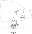
- Aircraft A is equipped with a power device, generally designated 1, to move aircraft A on the ground.
- the motorization device 1 comprises an electric motor 2 having an output shaft provided with means for its rotational connection to the wheels W of the front landing gear L to drive said wheels W in rotation.
- the motorization device also comprises an electronic control unit 3 connected, on the one hand, to the electric motor 2 to control it and, on the other hand, to a piloting interface 4 which is arranged in the cockpit of the aircraft A. From the piloting interface 4, the pilot of the aircraft A can emit control signals that the electronic control unit 3 is arranged to transform into signals for controlling the engine 2.
- the electronic control unit 3 comprises a processor (or another type of calculator such as an ASIC type circuit, an FPGA, a microcontroller, etc.) and a memory containing at least one program containing instructions arranged for the implementation of a control program for the motorization device 1.
- the piloting interface 4 comprises a switch 50 for activating the motorization which is movable between an “ON” position and an “OFF” position, and a control element 10, such as a joystick, arranged to be movable by the pilot of the aircraft A along a first scale 11 and a second scale 12 parallel to each other and connected to each other by a connecting section 13 comprising a neutral point 14.
- the first scale 11 comprises two ends 11.1, 11.2 corresponding respectively to a maximum speed and a minimum speed, here zero, to control the electric motor 2 between these two speeds, depending on the position of the control element 10 along the first scale 11, by implementing the first control law.
- the second control law determines a predetermined acceleration (for example an acceleration of 4 kn per second, it is recalled that 1 kn, or knot, is equal to 1852 m/h) greater than the acceleration determined by the third control law (for example 0.5 kn per second) for the same displacement amplitude of the control element 10.
- a predetermined acceleration for example an acceleration of 4 kn per second, it is recalled that 1 kn, or knot, is equal to 1852 m/h
- the second control law determines a predetermined acceleration equal to, or less than, the acceleration determined by the third control law for the same displacement amplitude of the control element 10.
- the acceleration predetermined by the first control law is compatible (i.e. more suitable) with movement in a straight line or along curved trajectories with large radii (resulting from a steering angle of the front landing gear leg between 0° and 30° for example) at relatively high speed such as during taxiing (at a speed between 10 and 20 kn for example).
- the acceleration predetermined by the second control law is more suitable for making small radius turns (resulting from a steering angle of the front landing gear leg between 31° and 74° for example) at relatively low speed (less than 10 kn for example) such as entering or leaving a parking space.
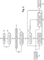
- the pilot who wishes to use the motorization device actuates the switch 50 (105) causing the motorization device 1 (110) and the control unit 3 to be powered up, which ensures a check of the state of the motorization device (115).
- the pilot then chooses by moving the control element 10 the type of rolling he wishes to carry out (120) and the direction of rolling (125).
- the control unit 3 will then control the electric motor 2 (130) by applying the control law resulting from the pilot's choice (131 for the first control law, 132 for the second, 133 for the third).
- the switch 20 pivots here between a taxiing position “Taxi” to command the control unit 3 to apply the first control law and a maneuvering position “Man” to command the control unit 3 to apply the second control law.
- the switch 30 pivots here between a “Forward” position to command the control unit 3 to drive the motor 2 forward and a “Reverse” position to command the control unit 3 to drive the motor 2 in reverse.
- the control unit 3 is arranged to take into account the selection of the forward or reverse direction only when the switch 20 is in the maneuvering position, in the taxiing position only forward movement being possible. It can be provided that placing the switch 20 in the taxiing position causes an LED to light up on the switch 30 to indicate that it is activated.
- the device may have a structure different from that described.
- the device of the invention can be used for the motorization of one or more wheels of an aircraft.
- the device can comprise two electric motors each associated with one of the main landing gears and connected to the wheels of this main landing gear.
- the switches 20, 30 can be replaced by any other device allowing selection and for example switches such as push buttons.
- the control element 10 can be replaced by any device allowing continuous variation such as for example a potentiometer.
- the control element 10 could also be replaced by a switch allowing speed selection from predefined values.
- a speed selection switch could be provided for taxiing and a speed selection switch for maneuvering, the actuation of one or other of the switches automatically selecting the corresponding control law.
- control element 10 and the switches 20, 30 can also be replaced by one or more touch screens.
- the mode of operation may be different from that described.
- the motorization device may be arranged so as not to operate in reverse.
- the mode of operation corresponds to that of the Figure 2 without operation 125.
- a single reverse speed can also be provided.
- Steering angles or speeds mentioned may differ from those given as a guide in the description.
Landscapes
- Engineering & Computer Science (AREA)
- Mechanical Engineering (AREA)
- Aviation & Aerospace Engineering (AREA)
- General Engineering & Computer Science (AREA)
- Radar, Positioning & Navigation (AREA)
- Remote Sensing (AREA)
- Physics & Mathematics (AREA)
- General Physics & Mathematics (AREA)
- Automation & Control Theory (AREA)
- Electric Propulsion And Braking For Vehicles (AREA)
- Arrangement Or Mounting Of Propulsion Units For Vehicles (AREA)
Claims (7)
- Antriebsvorrichtung (1) zum Bewegen eines am Boden befindlichen Luftfahrzeugs (A), das eine Landevorrichtung (L) mit Rädern (W) aufweist, wobei die Antriebsvorrichtung umfasst: zumindest einen Elektromotor (2) mit einer Ausgangswelle, die mit Drehverbindungsmitteln zu zumindest einem der Räder (W) der Landevorrichtung versehen ist, um das Rad in Drehbewegung zu versetzen; und eine elektronische Steuereinheit (3), welche einerseits mit dem Motor verbunden ist, um diesen zu steuern, und andererseits mit einer Ansteuerungsschnittstelle (4) verbunden ist, die ein Steuerelement (10) aufweist, welches der Pilot des Luftfahrzeugs verstellen kann, um Steuersignale auszugeben, die von der dafür ausgelegten elektronischen Steuereinheit in Motor-Ansteuerungssignale umgewandelt werden, wobei die Steuereinheit dafür ausgelegt ist, ein erstes Motorsteuerungsgesetz mit einer Dynamik auszuführen, die dafür bestimmt ist, eine Bewegungsgeschwindigkeit des Luftfahrzeugs zu begünstigen, und ein zweites Motorsteuerungsgesetz mit einer Dynamik auszuführen, die eine Manövrierfähigkeit des Luftfahrzeugs begünstigt, dadurch gekennzeichnet, dass das erste Steuerungsgesetz bei gleicher Verstellamplitude des Steuerelements (10) eine vorbestimmte Beschleunigung bestimmt, die größer ist als die durch das zweite Steuerungsgesetz bestimmte Beschleunigung.
- Vorrichtung nach Anspruch 1, wobei die Steuereinheit dafür ausgelegt ist, ein drittes Steuerungsgesetz mit einer Dynamik auszuführen, die dafür bestimmt ist, eine Manövrierfähigkeit des Luftfahrzeugs zu begünstigen, wobei das zweite Steuerungsgesetz dafür ausgelegt ist, den Motor in einer Vorwärtsrichtung zu steuern, und das dritte Steuerungsgesetz dafür ausgelegt ist, den Motor in einer Rückwärtsrichtung zu steuern.
- Vorrichtung nach Anspruch 1 oder 2, wobei das Steuerelement (10) derart ausgelegt ist, dass es von dem Piloten des Luftfahrtzeugs entlang einer ersten Skala (11) und einer zweiten Skala (12) verstellt werden kann, welche parallel zueinander verlaufen und durch einen Verbindungsabschnitt (13) miteinander verbunden sind, der einen Neutralpunkt umfasst, wobei die erste Skala zwei Enden (11.1, 11.2) umfasst, die jeweils einer maximalen Geschwindigkeit und einer minimalen Geschwindigkeit entsprechen, um unter Anwendung des ersten Steuerungsgesetzes den zumindest einen Motor je nach Position des Steuerelements zwischen diesen beiden Geschwindigkeiten zu steuern, und wobei die zweite Skala zwei Enden umfasst, die jeweils einer maximalen Geschwindigkeit und einer minimalen Geschwindigkeit entsprechen, um unter Anwendung des zweiten Steuerungsgesetzes den zumindest einen Motor je nach Position des Steuerelements zwischen diesen beiden Geschwindigkeiten zu steuern.
- Vorrichtung nach Anspruch 3, wobei die zweite Skala (12) umfasst: einen ersten Abschnitt (12.1) mit einem ersten Ende, das einer maximalen Geschwindigkeit bei Vorwärtsfahrt entspricht, und mit einem zweiten Ende, das einer Nullgeschwindigkeit entspricht und das mit einem ersten Ende eines zweiten Abschnitts (12.2) verbunden ist, welcher ein zweites Ende aufweist, das einer maximalen Geschwindigkeit bei Rückwärtsfahrt entspricht.
- Vorrichtung nach Anspruch 3, wobei die Ansteuerungsschnittstelle (4) ein Auswahlorgan (30) zum Auswählen einer Drehrichtung des zumindest einen Motors (2) bei der Anwendung des zweiten Steuerungsgesetzes umfasst.
- Vorrichtung nach Anspruch 1 oder nach Anspruch 2, wobei das Steuerelement (10) derart ausgelegt ist, dass es von dem Piloten des Luftfahrtzeugs entlang einer Skala (11) verstellt werden kann, welche zwei Enden umfasst, die jeweils einer maximalen Geschwindigkeit und einer minimalen Geschwindigkeit entsprechen, um den zumindest einen Motor je nach Position des Steuerelements zwischen diesen beiden Geschwindigkeiten und in Abhängigkeit zu einem Auswahlorgan (20) zum Auswählen des ersten Steuerungsgesetzes oder des zweiten Steuerungsgesetzes zu steuern.
- Vorrichtung nach Anspruch 6, wobei die Ansteuerungsschnittstelle (4) ein Auswahlorgan (30) zum Auswählen einer Drehrichtung des zumindest einen Motors bei der Anwendung des zweiten Steuerungsgesetzes umfasst.
Applications Claiming Priority (1)
| Application Number | Priority Date | Filing Date | Title |
|---|---|---|---|
| FR1873419A FR3090915B1 (fr) | 2018-12-19 | 2018-12-19 | Dispositif de motorisation d’un train d’atterrissage |
Publications (2)
| Publication Number | Publication Date |
|---|---|
| EP3671393A1 EP3671393A1 (de) | 2020-06-24 |
| EP3671393B1 true EP3671393B1 (de) | 2025-04-09 |
Family
ID=66676704
Family Applications (1)
| Application Number | Title | Priority Date | Filing Date |
|---|---|---|---|
| EP19217725.1A Active EP3671393B1 (de) | 2018-12-19 | 2019-12-18 | Steuervorrichtung des antriebs eines fahrwerks |
Country Status (5)
| Country | Link |
|---|---|
| US (1) | US11834157B2 (de) |
| EP (1) | EP3671393B1 (de) |
| CN (1) | CN111332460B (de) |
| CA (1) | CA3065871C (de) |
| FR (1) | FR3090915B1 (de) |
Families Citing this family (3)
| Publication number | Priority date | Publication date | Assignee | Title |
|---|---|---|---|---|
| US11407502B2 (en) * | 2020-02-24 | 2022-08-09 | Safran Landing Systems Canada Inc. | Taxi drive system for aircraft |
| FR3125508A1 (fr) | 2021-07-26 | 2023-01-27 | Dassault Aviation | Dispositif d'aide au pilotage d'un aéronef au taxiage, utilisant au moins un moteur et au moins un organe de freinage, aéronef et procédé associés |
| FR3125606B1 (fr) * | 2021-07-26 | 2024-01-19 | Dassault Aviat | Dispositif d'aide au pilotage en accélération d'un aéronef au taxiage en vue de contrôler sa vitesse, aéronef et procédés associés |
Family Cites Families (19)
| Publication number | Priority date | Publication date | Assignee | Title |
|---|---|---|---|---|
| US5038887A (en) * | 1989-05-08 | 1991-08-13 | M-B Company, Inc. Of Wisconsin | Control console for bidirectional service vehicle |
| US8897930B2 (en) * | 2005-03-01 | 2014-11-25 | Janice Ilene Bayer | Motor controller |
| US9139294B2 (en) * | 2005-03-01 | 2015-09-22 | Borealis Technical Limited | Motor controller |
| US7975960B2 (en) * | 2005-08-29 | 2011-07-12 | Borealis Technical Limited | Nosewheel control apparatus |
| US8109465B1 (en) * | 2007-08-02 | 2012-02-07 | Textron Innovations Inc. | Electro-magnetic up-lock for retractable landing gear |
| FR2930760B1 (fr) * | 2008-05-05 | 2010-09-10 | Airbus France | Dispositif annexe de deplacement au sol d'un vehicule aerien a turbine a air |
| CN101638041A (zh) * | 2009-04-24 | 2010-02-03 | 苏华 | 一种具有地面电行驶功能的直升飞机 |
| FR2944775B1 (fr) * | 2009-04-24 | 2013-03-08 | Messier Bugatti | Procede de deplacement d'un aeronef au sol |
| DE102012009106A1 (de) * | 2012-04-27 | 2013-10-31 | Liebherr-Aerospace Lindenberg Gmbh | Aktuator für ein Fahrwerk eines Luftfahrzeuges |
| US20140061373A1 (en) * | 2012-08-31 | 2014-03-06 | Michael Krenz | Controls for aircraft e-taxi |
| WO2014153182A2 (en) * | 2013-03-14 | 2014-09-25 | Joseph Cox | Cockpit control system for controlling ground travel in aircraft equipped with engine-free electric taxi system |
| GB201315012D0 (en) * | 2013-08-22 | 2013-10-02 | Airbus Uk Ltd | Aircraft autonomous pushback |
| CN107719650A (zh) * | 2013-09-05 | 2018-02-23 | 空中客车英国运营有限责任公司 | 用于飞行器的起落架的驱动系统 |
| US9751621B2 (en) * | 2013-11-13 | 2017-09-05 | Borealis Technical Limited | Steering control in an aircraft equipped with a wheel drive system |
| US9121487B2 (en) * | 2013-11-13 | 2015-09-01 | Honeywell International Inc. | Pilot interface for aircraft electric taxi system |
| US9688392B2 (en) * | 2014-06-26 | 2017-06-27 | Honeywell International Inc. | Thrust management and interface for aircraft taxi operations |
| US9541942B2 (en) * | 2014-12-15 | 2017-01-10 | Honeywell International Inc. | Aircraft electric taxi control interface and system |
| GB2537860A (en) * | 2015-04-28 | 2016-11-02 | Airbus Operations Sas | Aircraft steering system |
| US9630708B2 (en) * | 2015-08-28 | 2017-04-25 | Honeywell International Inc. | Aircraft landing gear wheel-drive system |
-
2018
- 2018-12-19 FR FR1873419A patent/FR3090915B1/fr active Active
-
2019
- 2019-12-18 EP EP19217725.1A patent/EP3671393B1/de active Active
- 2019-12-19 US US16/720,870 patent/US11834157B2/en active Active
- 2019-12-19 CA CA3065871A patent/CA3065871C/fr active Active
- 2019-12-19 CN CN201911316992.8A patent/CN111332460B/zh active Active
Also Published As
| Publication number | Publication date |
|---|---|
| CA3065871C (fr) | 2023-09-26 |
| CN111332460A (zh) | 2020-06-26 |
| EP3671393A1 (de) | 2020-06-24 |
| FR3090915A1 (fr) | 2020-06-26 |
| CN111332460B (zh) | 2024-02-09 |
| FR3090915B1 (fr) | 2021-01-22 |
| CA3065871A1 (fr) | 2020-06-19 |
| US20200198775A1 (en) | 2020-06-25 |
| US11834157B2 (en) | 2023-12-05 |
Similar Documents
| Publication | Publication Date | Title |
|---|---|---|
| EP3671393B1 (de) | Steuervorrichtung des antriebs eines fahrwerks | |
| EP2243703B1 (de) | Verfahren zum Bewegen eines Flugzeugs am Boden | |
| EP0835802B1 (de) | Steuerungshilfevorrichtung für ein Flugzeug mit einem elektrischen Flugsteuerungssystem | |
| EP0204598B1 (de) | Mit zwei gekuppelten Handgriffen versehenes Steuersystem | |
| EP2805887B1 (de) | System und Verfahren zur Steuerung eines Luftfahrzeuges | |
| EP3191365B1 (de) | Steuerorgan mit kraftrückmeldung für eine flugzeugsteuerungsvorrichtung mit einem notfallstrang | |
| EP3282334A1 (de) | Drohne mit feststehendem flügel, insbesondere vom typ nurflügelflugzeug, mit unterstützter manueller steuerung und automatik-steuerung | |
| FR2643502A1 (fr) | Dispositif de commande a manche basculant, notamment pour aeronef, et systeme comportant un tel dispositif | |
| FR2943316A1 (fr) | Procede d'uniformisation de la commande de poussee des moteurs d'un aeronef | |
| EP3271244B1 (de) | Vorrichtung zur flugsteuerung eines luftfahrzeugs | |
| EP1899212B1 (de) | Fahrzeuglenksteuersystem ohne mechanisches gestänge zwischen dem lenkrad und den gelenkten rädern | |
| FR2946021A1 (fr) | Procede et dispositif pour la detection d'une dissymetrie de poussee d'un aeronef lors d'un atterrissage | |
| FR2930973A1 (fr) | Procede et dispositif de mise en oeuvre des inverseurs de poussee d'un aeronef | |
| FR2903072A1 (fr) | Dispositif pour le deplacement autonome d'un aeronef au sol | |
| CA3021110A1 (fr) | Systeme de controle d'une trajectoire laterale d'un aeronef au sol | |
| FR2888009A1 (fr) | Dispositif de commande comportant deux manches couples pour permettre de placer des organes commandes dans des positions souhaitees | |
| FR3017367A1 (fr) | Aeronef comportant un train d'atterrissage dont une roue est pourvue d'un moteur electrique et un systeme de commande dudit moteur electrique | |
| EP1989104B1 (de) | Elektrisches steuersystem für eine flugzeuglenkschaufel | |
| CA3021106A1 (fr) | Ensemble d'affichage de trajectoires d'un aeronef | |
| EP1477872A1 (de) | Verfahren und Vorrichtung zur Steuerung eines Flugzeuges | |
| FR2903658A1 (fr) | Systeme de commandes de vol et de commande de direction au sol pour aeronef. | |
| CA2980295A1 (fr) | Organe de commande electrique, aeronef a voilure tournante et procede | |
| CA3021893A1 (fr) | Systeme de controle d'une trajectoire laterale d'un aeronef incluant un palonnier | |
| EP1883569B1 (de) | Fahrzeuglenksteuersystem ohne mechanisches gestänge zwischen dem lenkrad und den gelenkten rädern | |
| EP1588942A1 (de) | Schubhebel zur Steuerung des Betriebs von mindestens einem Triebwerk eines Flugzeugs |
Legal Events
| Date | Code | Title | Description |
|---|---|---|---|
| PUAI | Public reference made under article 153(3) epc to a published international application that has entered the european phase |
Free format text: ORIGINAL CODE: 0009012 |
|
| STAA | Information on the status of an ep patent application or granted ep patent |
Free format text: STATUS: THE APPLICATION HAS BEEN PUBLISHED |
|
| AK | Designated contracting states |
Kind code of ref document: A1 Designated state(s): AL AT BE BG CH CY CZ DE DK EE ES FI FR GB GR HR HU IE IS IT LI LT LU LV MC MK MT NL NO PL PT RO RS SE SI SK SM TR |
|
| AX | Request for extension of the european patent |
Extension state: BA ME |
|
| STAA | Information on the status of an ep patent application or granted ep patent |
Free format text: STATUS: REQUEST FOR EXAMINATION WAS MADE |
|
| 17P | Request for examination filed |
Effective date: 20201223 |
|
| RBV | Designated contracting states (corrected) |
Designated state(s): AL AT BE BG CH CY CZ DE DK EE ES FI FR GB GR HR HU IE IS IT LI LT LU LV MC MK MT NL NO PL PT RO RS SE SI SK SM TR |
|
| STAA | Information on the status of an ep patent application or granted ep patent |
Free format text: STATUS: EXAMINATION IS IN PROGRESS |
|
| 17Q | First examination report despatched |
Effective date: 20220406 |
|
| GRAP | Despatch of communication of intention to grant a patent |
Free format text: ORIGINAL CODE: EPIDOSNIGR1 |
|
| STAA | Information on the status of an ep patent application or granted ep patent |
Free format text: STATUS: GRANT OF PATENT IS INTENDED |
|
| INTG | Intention to grant announced |
Effective date: 20241028 |
|
| RIC1 | Information provided on ipc code assigned before grant |
Ipc: B64C 25/40 20060101ALN20241018BHEP Ipc: G05D 1/00 20060101AFI20241018BHEP |
|
| RIN1 | Information on inventor provided before grant (corrected) |
Inventor name: TELHADAS, DENIS Inventor name: BOISSARD, LAURENT Inventor name: FRAIM, JULIEN |
|
| GRAS | Grant fee paid |
Free format text: ORIGINAL CODE: EPIDOSNIGR3 |
|
| GRAA | (expected) grant |
Free format text: ORIGINAL CODE: 0009210 |
|
| STAA | Information on the status of an ep patent application or granted ep patent |
Free format text: STATUS: THE PATENT HAS BEEN GRANTED |
|
| AK | Designated contracting states |
Kind code of ref document: B1 Designated state(s): AL AT BE BG CH CY CZ DE DK EE ES FI FR GB GR HR HU IE IS IT LI LT LU LV MC MK MT NL NO PL PT RO RS SE SI SK SM TR |
|
| REG | Reference to a national code |
Ref country code: GB Ref legal event code: FG4D Free format text: NOT ENGLISH |
|
| REG | Reference to a national code |
Ref country code: CH Ref legal event code: EP |
|
| REG | Reference to a national code |
Ref country code: DE Ref legal event code: R096 Ref document number: 602019068365 Country of ref document: DE |
|
| REG | Reference to a national code |
Ref country code: IE Ref legal event code: FG4D Free format text: LANGUAGE OF EP DOCUMENT: FRENCH |
|
| REG | Reference to a national code |
Ref country code: NL Ref legal event code: MP Effective date: 20250409 |
|
| PG25 | Lapsed in a contracting state [announced via postgrant information from national office to epo] |
Ref country code: NL Free format text: LAPSE BECAUSE OF FAILURE TO SUBMIT A TRANSLATION OF THE DESCRIPTION OR TO PAY THE FEE WITHIN THE PRESCRIBED TIME-LIMIT Effective date: 20250409 |
|
| REG | Reference to a national code |
Ref country code: AT Ref legal event code: MK05 Ref document number: 1784092 Country of ref document: AT Kind code of ref document: T Effective date: 20250409 |
|
| PG25 | Lapsed in a contracting state [announced via postgrant information from national office to epo] |
Ref country code: FI Free format text: LAPSE BECAUSE OF FAILURE TO SUBMIT A TRANSLATION OF THE DESCRIPTION OR TO PAY THE FEE WITHIN THE PRESCRIBED TIME-LIMIT Effective date: 20250409 Ref country code: ES Free format text: LAPSE BECAUSE OF FAILURE TO SUBMIT A TRANSLATION OF THE DESCRIPTION OR TO PAY THE FEE WITHIN THE PRESCRIBED TIME-LIMIT Effective date: 20250409 Ref country code: PT Free format text: LAPSE BECAUSE OF FAILURE TO SUBMIT A TRANSLATION OF THE DESCRIPTION OR TO PAY THE FEE WITHIN THE PRESCRIBED TIME-LIMIT Effective date: 20250811 |
|
| REG | Reference to a national code |
Ref country code: LT Ref legal event code: MG9D |
|
| PG25 | Lapsed in a contracting state [announced via postgrant information from national office to epo] |
Ref country code: GR Free format text: LAPSE BECAUSE OF FAILURE TO SUBMIT A TRANSLATION OF THE DESCRIPTION OR TO PAY THE FEE WITHIN THE PRESCRIBED TIME-LIMIT Effective date: 20250710 Ref country code: NO Free format text: LAPSE BECAUSE OF FAILURE TO SUBMIT A TRANSLATION OF THE DESCRIPTION OR TO PAY THE FEE WITHIN THE PRESCRIBED TIME-LIMIT Effective date: 20250709 |
|
| PG25 | Lapsed in a contracting state [announced via postgrant information from national office to epo] |
Ref country code: PL Free format text: LAPSE BECAUSE OF FAILURE TO SUBMIT A TRANSLATION OF THE DESCRIPTION OR TO PAY THE FEE WITHIN THE PRESCRIBED TIME-LIMIT Effective date: 20250409 |
|
| PG25 | Lapsed in a contracting state [announced via postgrant information from national office to epo] |
Ref country code: BG Free format text: LAPSE BECAUSE OF FAILURE TO SUBMIT A TRANSLATION OF THE DESCRIPTION OR TO PAY THE FEE WITHIN THE PRESCRIBED TIME-LIMIT Effective date: 20250409 |
|
| PG25 | Lapsed in a contracting state [announced via postgrant information from national office to epo] |
Ref country code: HR Free format text: LAPSE BECAUSE OF FAILURE TO SUBMIT A TRANSLATION OF THE DESCRIPTION OR TO PAY THE FEE WITHIN THE PRESCRIBED TIME-LIMIT Effective date: 20250409 |
|
| PG25 | Lapsed in a contracting state [announced via postgrant information from national office to epo] |
Ref country code: AT Free format text: LAPSE BECAUSE OF FAILURE TO SUBMIT A TRANSLATION OF THE DESCRIPTION OR TO PAY THE FEE WITHIN THE PRESCRIBED TIME-LIMIT Effective date: 20250409 |
|
| PG25 | Lapsed in a contracting state [announced via postgrant information from national office to epo] |
Ref country code: RS Free format text: LAPSE BECAUSE OF FAILURE TO SUBMIT A TRANSLATION OF THE DESCRIPTION OR TO PAY THE FEE WITHIN THE PRESCRIBED TIME-LIMIT Effective date: 20250709 |
|
| PG25 | Lapsed in a contracting state [announced via postgrant information from national office to epo] |
Ref country code: IS Free format text: LAPSE BECAUSE OF FAILURE TO SUBMIT A TRANSLATION OF THE DESCRIPTION OR TO PAY THE FEE WITHIN THE PRESCRIBED TIME-LIMIT Effective date: 20250809 |
|
| PG25 | Lapsed in a contracting state [announced via postgrant information from national office to epo] |
Ref country code: LV Free format text: LAPSE BECAUSE OF FAILURE TO SUBMIT A TRANSLATION OF THE DESCRIPTION OR TO PAY THE FEE WITHIN THE PRESCRIBED TIME-LIMIT Effective date: 20250409 |
|
| PGFP | Annual fee paid to national office [announced via postgrant information from national office to epo] |
Ref country code: GB Payment date: 20251229 Year of fee payment: 7 |
|
| REG | Reference to a national code |
Ref country code: DE Ref legal event code: R097 Ref document number: 602019068365 Country of ref document: DE |
|
| PG25 | Lapsed in a contracting state [announced via postgrant information from national office to epo] |
Ref country code: SM Free format text: LAPSE BECAUSE OF FAILURE TO SUBMIT A TRANSLATION OF THE DESCRIPTION OR TO PAY THE FEE WITHIN THE PRESCRIBED TIME-LIMIT Effective date: 20250409 Ref country code: DK Free format text: LAPSE BECAUSE OF FAILURE TO SUBMIT A TRANSLATION OF THE DESCRIPTION OR TO PAY THE FEE WITHIN THE PRESCRIBED TIME-LIMIT Effective date: 20250409 |
|
| PGFP | Annual fee paid to national office [announced via postgrant information from national office to epo] |
Ref country code: FR Payment date: 20251222 Year of fee payment: 7 |
|
| PG25 | Lapsed in a contracting state [announced via postgrant information from national office to epo] |
Ref country code: CZ Free format text: LAPSE BECAUSE OF FAILURE TO SUBMIT A TRANSLATION OF THE DESCRIPTION OR TO PAY THE FEE WITHIN THE PRESCRIBED TIME-LIMIT Effective date: 20250409 |
|
| PG25 | Lapsed in a contracting state [announced via postgrant information from national office to epo] |
Ref country code: EE Free format text: LAPSE BECAUSE OF FAILURE TO SUBMIT A TRANSLATION OF THE DESCRIPTION OR TO PAY THE FEE WITHIN THE PRESCRIBED TIME-LIMIT Effective date: 20250409 |
|
| PG25 | Lapsed in a contracting state [announced via postgrant information from national office to epo] |
Ref country code: RO Free format text: LAPSE BECAUSE OF FAILURE TO SUBMIT A TRANSLATION OF THE DESCRIPTION OR TO PAY THE FEE WITHIN THE PRESCRIBED TIME-LIMIT Effective date: 20250409 Ref country code: SK Free format text: LAPSE BECAUSE OF FAILURE TO SUBMIT A TRANSLATION OF THE DESCRIPTION OR TO PAY THE FEE WITHIN THE PRESCRIBED TIME-LIMIT Effective date: 20250409 |
|
| PG25 | Lapsed in a contracting state [announced via postgrant information from national office to epo] |
Ref country code: IT Free format text: LAPSE BECAUSE OF FAILURE TO SUBMIT A TRANSLATION OF THE DESCRIPTION OR TO PAY THE FEE WITHIN THE PRESCRIBED TIME-LIMIT Effective date: 20250409 |
|
| PLBE | No opposition filed within time limit |
Free format text: ORIGINAL CODE: 0009261 |
|
| STAA | Information on the status of an ep patent application or granted ep patent |
Free format text: STATUS: NO OPPOSITION FILED WITHIN TIME LIMIT |
|
| REG | Reference to a national code |
Ref country code: CH Ref legal event code: L10 Free format text: ST27 STATUS EVENT CODE: U-0-0-L10-L00 (AS PROVIDED BY THE NATIONAL OFFICE) Effective date: 20260218 |
|
| 26N | No opposition filed |
Effective date: 20260112 |
|
| PGFP | Annual fee paid to national office [announced via postgrant information from national office to epo] |
Ref country code: DE Payment date: 20251222 Year of fee payment: 7 |