EP3671399B1 - Procede de determination d'une consigne minimale preferentielle de puissance, procede de pilotage d'une pluralite de chauffe-eaux et dispositif associe - Google Patents
Procede de determination d'une consigne minimale preferentielle de puissance, procede de pilotage d'une pluralite de chauffe-eaux et dispositif associe Download PDFInfo
- Publication number
- EP3671399B1 EP3671399B1 EP19218815.9A EP19218815A EP3671399B1 EP 3671399 B1 EP3671399 B1 EP 3671399B1 EP 19218815 A EP19218815 A EP 19218815A EP 3671399 B1 EP3671399 B1 EP 3671399B1
- Authority
- EP
- European Patent Office
- Prior art keywords
- consumer
- determining
- instant
- set point
- power set
- Prior art date
- Legal status (The legal status is an assumption and is not a legal conclusion. Google has not performed a legal analysis and makes no representation as to the accuracy of the status listed.)
- Active
Links
Images


Classifications
-
- F—MECHANICAL ENGINEERING; LIGHTING; HEATING; WEAPONS; BLASTING
- F24—HEATING; RANGES; VENTILATING
- F24D—DOMESTIC- OR SPACE-HEATING SYSTEMS, e.g. CENTRAL HEATING SYSTEMS; DOMESTIC HOT-WATER SUPPLY SYSTEMS; ELEMENTS OR COMPONENTS THEREFOR
- F24D19/00—Details
- F24D19/10—Arrangement or mounting of control or safety devices
- F24D19/1006—Arrangement or mounting of control or safety devices for water heating systems
- F24D19/1051—Arrangement or mounting of control or safety devices for water heating systems for domestic hot water
- F24D19/1063—Arrangement or mounting of control or safety devices for water heating systems for domestic hot water counting of energy consumption
-
- G—PHYSICS
- G05—CONTROLLING; REGULATING
- G05D—SYSTEMS FOR CONTROLLING OR REGULATING NON-ELECTRIC VARIABLES
- G05D23/00—Control of temperature
- G05D23/19—Control of temperature characterised by the use of electric means
- G05D23/1919—Control of temperature characterised by the use of electric means characterised by the type of controller
- G05D23/1924—Control of temperature characterised by the use of electric means characterised by the type of controller using thermal energy, the availability of which is aleatory
-
- F—MECHANICAL ENGINEERING; LIGHTING; HEATING; WEAPONS; BLASTING
- F24—HEATING; RANGES; VENTILATING
- F24D—DOMESTIC- OR SPACE-HEATING SYSTEMS, e.g. CENTRAL HEATING SYSTEMS; DOMESTIC HOT-WATER SUPPLY SYSTEMS; ELEMENTS OR COMPONENTS THEREFOR
- F24D17/00—Domestic hot-water supply systems
- F24D17/0036—Domestic hot-water supply systems with combination of different kinds of heating means
- F24D17/0063—Domestic hot-water supply systems with combination of different kinds of heating means solar energy and conventional heaters
-
- F—MECHANICAL ENGINEERING; LIGHTING; HEATING; WEAPONS; BLASTING
- F24—HEATING; RANGES; VENTILATING
- F24D—DOMESTIC- OR SPACE-HEATING SYSTEMS, e.g. CENTRAL HEATING SYSTEMS; DOMESTIC HOT-WATER SUPPLY SYSTEMS; ELEMENTS OR COMPONENTS THEREFOR
- F24D19/00—Details
- F24D19/10—Arrangement or mounting of control or safety devices
- F24D19/1006—Arrangement or mounting of control or safety devices for water heating systems
- F24D19/1051—Arrangement or mounting of control or safety devices for water heating systems for domestic hot water
- F24D19/1057—Arrangement or mounting of control or safety devices for water heating systems for domestic hot water the system uses solar energy
-
- F—MECHANICAL ENGINEERING; LIGHTING; HEATING; WEAPONS; BLASTING
- F24—HEATING; RANGES; VENTILATING
- F24H—FLUID HEATERS, e.g. WATER OR AIR HEATERS, HAVING HEAT-GENERATING MEANS, e.g. HEAT PUMPS, IN GENERAL
- F24H15/00—Control of fluid heaters
- F24H15/10—Control of fluid heaters characterised by the purpose of the control
- F24H15/144—Measuring or calculating energy consumption
- F24H15/148—Assessing the current energy consumption
-
- F—MECHANICAL ENGINEERING; LIGHTING; HEATING; WEAPONS; BLASTING
- F24—HEATING; RANGES; VENTILATING
- F24H—FLUID HEATERS, e.g. WATER OR AIR HEATERS, HAVING HEAT-GENERATING MEANS, e.g. HEAT PUMPS, IN GENERAL
- F24H15/00—Control of fluid heaters
- F24H15/10—Control of fluid heaters characterised by the purpose of the control
- F24H15/144—Measuring or calculating energy consumption
- F24H15/152—Forecasting future energy consumption
-
- F—MECHANICAL ENGINEERING; LIGHTING; HEATING; WEAPONS; BLASTING
- F24—HEATING; RANGES; VENTILATING
- F24H—FLUID HEATERS, e.g. WATER OR AIR HEATERS, HAVING HEAT-GENERATING MEANS, e.g. HEAT PUMPS, IN GENERAL
- F24H15/00—Control of fluid heaters
- F24H15/10—Control of fluid heaters characterised by the purpose of the control
- F24H15/156—Reducing the quantity of energy consumed; Increasing efficiency
-
- F—MECHANICAL ENGINEERING; LIGHTING; HEATING; WEAPONS; BLASTING
- F24—HEATING; RANGES; VENTILATING
- F24D—DOMESTIC- OR SPACE-HEATING SYSTEMS, e.g. CENTRAL HEATING SYSTEMS; DOMESTIC HOT-WATER SUPPLY SYSTEMS; ELEMENTS OR COMPONENTS THEREFOR
- F24D2200/00—Heat sources or energy sources
- F24D2200/02—Photovoltaic energy
-
- F—MECHANICAL ENGINEERING; LIGHTING; HEATING; WEAPONS; BLASTING
- F24—HEATING; RANGES; VENTILATING
- F24D—DOMESTIC- OR SPACE-HEATING SYSTEMS, e.g. CENTRAL HEATING SYSTEMS; DOMESTIC HOT-WATER SUPPLY SYSTEMS; ELEMENTS OR COMPONENTS THEREFOR
- F24D2200/00—Heat sources or energy sources
- F24D2200/15—Wind energy
-
- F—MECHANICAL ENGINEERING; LIGHTING; HEATING; WEAPONS; BLASTING
- F24—HEATING; RANGES; VENTILATING
- F24H—FLUID HEATERS, e.g. WATER OR AIR HEATERS, HAVING HEAT-GENERATING MEANS, e.g. HEAT PUMPS, IN GENERAL
- F24H1/00—Water heaters, e.g. boilers, continuous-flow heaters or water-storage heaters
- F24H1/18—Water-storage heaters
-
- F—MECHANICAL ENGINEERING; LIGHTING; HEATING; WEAPONS; BLASTING
- F24—HEATING; RANGES; VENTILATING
- F24H—FLUID HEATERS, e.g. WATER OR AIR HEATERS, HAVING HEAT-GENERATING MEANS, e.g. HEAT PUMPS, IN GENERAL
- F24H15/00—Control of fluid heaters
- F24H15/20—Control of fluid heaters characterised by control inputs
-
- F—MECHANICAL ENGINEERING; LIGHTING; HEATING; WEAPONS; BLASTING
- F24—HEATING; RANGES; VENTILATING
- F24H—FLUID HEATERS, e.g. WATER OR AIR HEATERS, HAVING HEAT-GENERATING MEANS, e.g. HEAT PUMPS, IN GENERAL
- F24H15/00—Control of fluid heaters
- F24H15/20—Control of fluid heaters characterised by control inputs
- F24H15/212—Temperature of the water
- F24H15/215—Temperature of the water before heating
-
- F—MECHANICAL ENGINEERING; LIGHTING; HEATING; WEAPONS; BLASTING
- F24—HEATING; RANGES; VENTILATING
- F24H—FLUID HEATERS, e.g. WATER OR AIR HEATERS, HAVING HEAT-GENERATING MEANS, e.g. HEAT PUMPS, IN GENERAL
- F24H15/00—Control of fluid heaters
- F24H15/20—Control of fluid heaters characterised by control inputs
- F24H15/254—Room temperature
Definitions
- the technical field of the invention is that of controlling the consumption of hot water for the purpose of maximizing the self-consumption of renewable energy. More particularly, the invention relates to a method for determining a preferential minimum power setpoint as well as a method for controlling a plurality of water heaters on a network comprising a plurality of consumers i. It also relates to a device implementing such methods.
- electric water heaters can have several compartments or several resistors positioned at different heights of the water heater, so as to provide modularity in the heating of the water and to provide the possibility of controlling consumption and temperature for different volumes of water.
- production or consumption forecasts as well as information concerning the state of each consumer (number of occupants associated with the consumer). , past hot water consumption, etc.).
- the document FR 3 033 394 A1 presents a water heater management system with a dedicated photovoltaic installation that absorbs the energy produced by the photovoltaic panels in thermal form in the installation's water heater (s).
- the system also uses the weather forecast so as to determine whether the water heater should use the energy supplied by the photovoltaic panels (daytime load) or, on the contrary, use the energy from the network to which the system is connected (nighttime load).
- EWHs Electric Water Heaters
- WO2014 / 055059 discloses a method for determining a preferential minimum power setpoint by a consumer, said consumer comprising a radiator.
- control of an installation can therefore be done in two different ways.
- the first is based on a balanced distribution. It has the advantage of requiring only a few data, but it does not allow optimal control, that is to say control maximizing the consumption of energy produced locally.
- the second is based on an optimal distribution calculated using mathematical methods resulting from operational research requiring the forecast of the electricity consumption of the various consumers as well as the forecast of local production. It is therefore based on forecasts consisting of long series of data over an entire production / consumption period (typically a day) which often present a non-negligible level of error leading either to consumer dissatisfaction in terms of comfort and / or need, or a sub-optimal piloting.
- the invention offers a solution to the problems mentioned above, by proposing a control method that does not require production forecasts, but generates instructions based on data relating to the current production period.
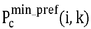
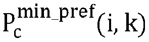
- the method according to a second aspect of the invention comprises, before receiving step, for each consumer i of the plurality of consumers i, a step of implementing a method according to a first aspect of the invention. 'invention so as to obtain, for each consumer i, a preferential minimum power setpoint P vs min _ pref i k .
- a third aspect of the invention relates to a device comprising means for implementing a method according to a first or a second aspect of the invention.
- a fourth aspect of the invention relates to a computer program comprising instructions which lead the device according to a third aspect of the invention to execute the steps of the method according to a first or a second aspect of the invention.
- a fifth aspect of the invention relates to a computer readable medium, on which is recorded the computer program according to a fourth aspect of the invention.
- FIG. 1 shows a flowchart of a method according to a first aspect of the invention.
- FIG. 2 shows a flowchart of a method according to a second aspect of the invention.
- Each consumer is associated with an index i, said index being such that i ⁇ [1, I], with I the total number of consumers.
- Each time slot of the production / consumption period is associated with an index k, said index being such that k ⁇ [1, K], with K the total number of time slots during the production / consumption period.
- each time range has a time duration ⁇ so that K ⁇ ⁇ is equal to the duration of the production / consumption period.
- the expression “time k” will be used to designate the time range k.
- ⁇ can be equal to one minute and K equal to 1440, which corresponds to a production period of 24 hours.
- the instant k must be understood as the instant during which the state of the consumer is determined and during which the setpoint is established using a method according to the invention.
- the power consumed by the water heater of consumer i at time k is denoted by P (i, k).
- P (i, k 1 : k 2 ) the power consumed by the water heater of consumer i between times k 1 and k 2 is denoted by P (i, k 1 : k 2 ) and corresponds to a vector whose coordinates are the power consumed by the heater. consumer water! during times k 1 to k 2 .
- the vector P ( i , 1: 3) is equivalent to the vector ( P ( i , 1), P ( i, 2), P ( i, 3)).
- T (i, k) The temperature of the water heater of consumer i at time k is denoted T (i, k).
- T (i, k 1 : k 2 ) the temperature of the water heater of consumer i between times k 1 and k 2 is denoted T (i, k 1 : k 2 ) (this is again a vector).
- the setpoint power given to the water heater of consumer i at time k is denoted by P c (i, k).
- the setpoint power given to the water heater of consumer i between instants k 1 and k 2 is denoted P vs min i , k 1 : k 2 (this is again a vector).
- the number of people associated with a consumer i at time k is denoted Per (i, k). This number of people is always such that 0 ⁇ Per (i, k) ⁇ N i , with N i the maximum number of people associated with consumer i.
- the number of people associated with the consumer i between instants k 1 and k 2 is denoted Per (i, k 1 : k 2 ) (this is again a vector).
- the quantity of hot water consumed by consumer i during the time period k is denoted by Water (i, k).
- Water (i, k) the quantity of hot water consumed by consumer i between times k 1 and k 2 is denoted Water (i, k 1 : k 2 ) (this is again a vector).
- V total ( i ) The total quantity of water in the hot water tank when the latter is full of consumer i is denoted by V total ( i ) .
- T cold water ( i, k ) The temperature of the cold water at the inlet of the hot water tank of consumer i at time k.
- R ( i ) The factor for converting the electrical power into thermal power relating to the water heater of consumer i is denoted by R ( i ).
- T amb The ambient temperature of the hot water tank room associated with consumer i at time k.
- the thermal dispersion factor between the tank and the ambient temperature associated with consumer i is denoted by Loss factor ( i ) .
- a first aspect of the invention illustrated on figure 1 relates to a method 100 for determining a preferential minimum power setpoint by a consumer i, said consumer comprising an electric water heater.
- the hot water from the water heater can in particular be used for sanitary facilities, for air conditioning and / or heating.
- the method therefore aims to determine (for possibly providing it to a management system) a setpoint value to be observed for proper management of the water heater of a given consumer i.
- the method 100 comprises a step 1E1 of determining the state of the consumer i at the instant k.
- the state of a consumer can include the power consumed by the water heater P (i, k). It can also include the number of people Per (i, k) associated with consumer i at time k. Indeed, each consumer i can correspond to a household or more generally to a building, that is to say to one or more people. Of course, the power consumed by the water heater P (i, k) of consumer i will therefore depend on the number of people Per (i, k) present at each instant k.
- step 1E1 of determining the state of consumer i at time k comprises a sub-step 1E11 of acquiring power P (i, k) consumed by the water heater of consumer i at l 'instant k. This acquisition can for example be done using a communicating meter. At the end of this sub-step 1E11, the power P (i, k) consumed by the water heater of consumer i at time k is known.
- step 1E1 of determining the state of the consumer! also comprises a sub-step 1E12 of determining the number of people Per (i, k) at the instant k associated with the consumer i.
- the number of people associated with consumer i can for example be determined by measuring the quantity of CO 2 . This number can also be determined from geolocation data obtained using a smartphone (or mobile phone). It is also possible to use other information, for example working hours in the case of a company or else a combination of said information.
- the number of people Per (i, k) associated with consumer i at time k is known.
- step 1E1 of determining the state of consumer i at time k we know the number of people Per (i, k) as well as the power consumed P (i, k) by the heater -water at instant k associated with said consumer i.
- the method 100 further comprises a step 1E2 of determining a minimum power setpoint P vs min i , k at time k as a function of the state of consumer i determined during step 1E1 of determining the state of consumer i at time k.
- step 1E2 of determining a minimum power setpoint P vs min i , k at time k includes a sub-step 1E21 for determining the minimum quantity of hot water Min water (i, k) required at time k as a function of the number of people Per (i, k) associated with consumer i .
- the quantity of hot water Water min (i, k) associated with consumer i is determined by taking into account the preferences of each person present.
- Step 1E2 of determining the minimum power setpoint P vs min i , k at instant k also comprises a sub-step 1E22 of determining a minimum power setpoint P vs min i , k at the instant k as a function of the minimum quantity of hot water Min water (i, k) necessary at the instant k determined in the preceding sub-step 1E21.
- the conversion factor of electrical power into thermal power R ( i ) and / or the thermal dispersion factor between the tank and the ambient temperature Loss factor (i) can be determined from measurements and / or supplied by the manufacturer of the water heater.
- the value of this temperature may be chosen as being equal to a predetermined value, for example 15 ° C in summer and 12 ° C in winter.
- the value of this temperature can be chosen as being equal to a predetermined value, for example equal to 22 ° C.
- the method 100 then comprises a step 1E3 of determining a minimum power setpoint P vs min i , k + 1 : K at times k + 1 at K.
- step 1E3 of determining a minimum power setpoint P vs min i , k + 1 : K at times k + 1 to K comprises a sub-step 1E31 of determining the quantity of forecast hot water Water prev (i, k + 1: K) consumed at times k + 1 to K as a function of the number of people associated with said consumer plus a person (i.e. Per (i, k) + 1 if Per (i, k) + 1 ⁇ N i or N i otherwise) at times k + 1 to K, denoted Per +1 (i, k + 1: K) in the following.
- the temperature T (i, k) of the hot water is also taken into account during the sub-step of determining the predicted quantity of hot water Water prev (i, k + 1: K ) at times k + 1 at K.
- Water prev (i, 3: 5) [Water prev (i, 3), Water prev (i, 4), Water prev ( i , 5)].
- the sub-step 1E31 of determining the quantity of predicted hot water Water prev (i, k + 1: K) consumed at times k + 1 to K comprises a phase of determining one hour d arrival of the additional person, the forecast quantity of hot water Water prev (i, k + 1: K) then being determined as a function of said arrival time.
- the estimated arrival time can be determined by a learning method, based on the actual arrival times previously recorded.
- the estimated time of arrival can be determined as a function of working hours or any other information concerning the schedule of the person or persons associated with the consumer i considered.
- the estimated time of arrival can be determined using geolocation information concerning the persons associated with the consumer i considered.
- step 1E3 of determining a minimum power setpoint P vs min i , k + 1 : K at times k + 1 to K also comprises a sub-step 1E32 of determining the minimum power setpoint P vs min i , k + 1 : K at times k + 1 at K as a function of the quantity of predicted hot water Water prev (i, k + 1: K) consumed at times k + 1 at K determined during the preceding sub-step 1E31.
- the temperature T water ( i, k ' + 1) is iteratively calculated from T water ( i, k' ) .
- the method according to a first aspect of the invention also comprises a step 1E4 of determining the minimum preferential power setpoint P vs min_pref i k depending on the minimum power setpoint P vs min i k at instant k and the minimum power setpoint P vs min i , k + 1 : K at times k + 1 at K.
- a second aspect of the invention illustrated on figure 2 relates to a method 200 for controlling a plurality of water heaters on a network comprising a plurality of consumers i, each consumer i of the plurality of consumers i comprising a water heater of the plurality of water heaters.
- the method aims to control the water heaters so as to optimize the consumption of electrical energy, for example to take into account the presence of an intermittent source of electrical energy such as photovoltaic panels or a wind turbine. More particularly, the method aims to determine, for each consumer i, an optimum power setpoint at the instant k denoted by P c (i, k).
- the method 200 comprises a reception step 2E1, from each consumer! of the plurality of consumers i, of a preferential minimum power setpoint P vs min_pref i k .
- Other data may possibly be received during this step, for example data concerning the state of each consumer i .
- the method according to a second aspect of the invention comprises, before receiving step 2E1, for each consumer i of the plurality of consumers i, a step 2E0 of implementing a method 100 according to a first aspect of the invention, so as to obtain, for each consumer i, a preferential minimum power setpoint P vs min_pref i k .
- consumers can send the minimum preferential power settings to a control system, the latter then being received during reception step 2E1.
- Other data may possibly be transmitted to the control system during this step, for example data concerning the state of each consumer i .
- Such a communication can, for example, use PLCs (for line power lines) or even wireless means of communication.
- These preferential minimum power settings P vs min_pref i k can then be used to determine optimized setpoints (for example to promote the use of locally produced electrical energy) for each consumer i.
- the method according to a second aspect of the invention comprises, for each consumer i of the plurality of consumers i, a step 2E2 of determining a power setpoint P c (i, k) at the instant k in as a function of the minimum preferential power setpoint P vs min_pref i k .
- step 2E2 of determining a power setpoint P c (i, k) at time k comprises a sub-step 2E21 of determining the optimum electrical modulation at time k.
- the optimal electrical modulation is the modulation that maximizes self-consumption or network service. More generally, the optimum electrical modulation is a function of the objectives set for the piloting process.
- the determination of an optimal electrical modulation is known to those skilled in the art and will therefore not be detailed here. The interested reader can for example refer to the problem known as "of the backpacks" or " Knapsack problem " in English, and in particular to the document “A dynamic programming method with lists for the knapsack sharing problem”, V. Boyer, D. El Baz, M.
- step 2E2 of determining a power setpoint P c (i, k) at instant k comprises a sub-step 2E22 of determining an optimum power setpoint P vs opt i k corresponding to the distribution of the modulation among each consumer i, said distribution being carried out in proportion to the minimum preferential set points.
- the modulation Mod (k) may be advantageous not to distribute the modulation Mod (k) in proportion to the minimum preferential setpoints, but rather so as to take into account the satisfaction of each consumer i at the instant k, denoted S (i, k ), said satisfaction S (i, k) being for example equal to 1 when the satisfaction is maximum and to 0 when the latter is minimum.
- the satisfaction S (i, k) is a function of the quantity of hot water and / or of the number of people and / or of the temperature of the hot water in the balloon.
- T opt ( i, k ) is an optimum hot water temperature associated with consumer i at time k.
- the latter can for example be chosen by the person or persons associated with said consumer i .
- the latter can be chosen as being equal to a predefined value, for example 55 ° C.
- the distribution is then obtained by determining, for each consumer i , the optimum power P vs opt i k maximizing service satisfaction and power distribution efficiency, i.e. maximizing the following relationship: ⁇ S i k ⁇ not i k
- the maximization is done by ensuring that the inequality P i k ⁇ P vs min _ pref i , k is respected for each consumer i.
- each consumer i is associated with an optimal setpoint power P vs opt i k at the instant k making it possible to optimize the satisfaction of the latter.
- step 2E2 of determining a power setpoint P c (i, k) at instant k comprises a sub-step 2E23 of determining the power setpoint P c (i, k) , said power setpoint P c (i, k) at instant k being the maximum between the optimum power setpoint P vs opt i k (which corresponds to the modulation distributed between the different consumers i) and the minimum preferential setpoint P vs min _ pref i , k . This ensures that the minimum preferential setpoint is always respected.
- a third aspect of the invention relates to a device comprising the means for implementing a method 100 according to a first aspect of the invention.
- the device comprises means for measuring the electrical consumption P (i, k) of a water heater as well as the water temperature T (i, k) of said water heater.
- the device further comprises a calculation means (for example a processor) associated with a memory (for example a RAM memory), said memory being configured to store the instructions as well as the data necessary for the execution of a method 100 according to a first aspect of the invention.
- the device also comprises communication means (for example means making it possible to establish a PLC communication) so that said device can exchange data with a remote management system.
- a fourth aspect of the invention relates to a control system comprising the means for implementing a method 200 according to a second aspect of the invention.
- the device comprises a means calculation (for example a processor) associated with a memory (for example a RAM memory), said memory being configured to store the instructions as well as the data necessary for the execution of a method 200 according to a second aspect of the invention .
- the device also comprises communication means (for example means making it possible to establish a PLC communication) so that said system can exchange data with one or more remote devices, each remote device corresponding to a consumer. .
Landscapes
- Engineering & Computer Science (AREA)
- Physics & Mathematics (AREA)
- General Engineering & Computer Science (AREA)
- Thermal Sciences (AREA)
- Chemical & Material Sciences (AREA)
- Combustion & Propulsion (AREA)
- Mechanical Engineering (AREA)
- Sustainable Energy (AREA)
- Sustainable Development (AREA)
- Life Sciences & Earth Sciences (AREA)
- General Physics & Mathematics (AREA)
- Automation & Control Theory (AREA)
- Management, Administration, Business Operations System, And Electronic Commerce (AREA)
- Heat-Pump Type And Storage Water Heaters (AREA)
Description
- Le domaine technique de l'invention est celui du pilotage de la consommation d'eau chaude à des fins de maximisation de l'autoconsommation d'énergie renouvelable. Plus particulièrement, l'invention concerne un procédé de détermination d'une consigne minimale préférentielle de puissance ainsi qu'un procédé de pilotage d'une pluralité de chauffe-eaux sur un réseau comportant une pluralité de consommateurs i. Elle concerne également un dispositif mettant en oeuvre de tels procédés.
- Dans le cadre de la production électrique renouvelable, par exemple à l'aide de panneau photovoltaïque, il est connu de piloter individuellement chaque installation de sorte à satisfaire la demande de chaque consommateur tout en maximisant la consommation de l'énergie produite localement. Cependant, il peut être avantageux de gérer la production, non plus de manière individuelle, mais de manière collective en répartissant l'énergie produite localement entre différents consommateurs en fonction des besoins. A cette fin, il est possible de compléter l'installation par des batteries ou toute autre forme de stockage de sorte à maximiser l'utilisation de l'énergie produite localement. Cependant, afin de limiter l'usage de batterie, il est également possible d'utiliser les équipements électriques de production d'eau chaude en assimilant ces derniers soit à une charge électrique qui va donc consommer de l'énergie, soit à un moyen de stockage de la chaleur (ou moyen de stockage thermique) qui va donc stocker de l'énergie. Un tel système peut donc être piloté à l'aide de deux consignes : l'activation ou la désactivation de la consommation électrique lié au chauffage de l'eau ou une consigne de température de l'eau chaude.
- De manière générale, les chauffe-eaux électriques peuvent présenter plusieurs compartiments ou plusieurs résistances positionnés à différentes hauteurs du chauffe-eau, de manière à apporter de la modularité dans le chauffage de l'eau et à fournir la possibilité de piloter la consommation et la température pour des volumes d'eau différents. Lorsque l'on cherche à optimiser la production et la consommation d'eau chaude, il est nécessaire de prendre en compte les prévisions de production ou de consommation ainsi que des informations concernant l'état de chaque consommateur (nombre d'occupant associé au consommateur, consommation d'eau chaude passée, etc.). De plus, il est nécessaire de tenir compte de la notion de besoin et de confort.
- Pour cela, les compteurs communicants modernes, tels que le compteur Linky, permettent de communiquer en temps réel la consommation électrique à des fins de pilotage intelligent des installations électriques. Par exemple, le document
FR 3 033 394 A1 - Le document
WO2014/055059 divulgue un procédé de détermination d'une consigne minimale préférentielle de puissance par un consommateur, ledit consommateur comprenant un radiateur. - De manière générale, le pilotage d'une installation peut donc se faire de deux manières différentes. La première repose sur une répartition équilibrée. Elle présente l'avantage de ne nécessiter que peu de données, mais elle ne permet pas un pilotage optimal, c'est-à-dire un pilotage maximisant la consommation de l'énergie produite localement. La deuxième repose sur une répartition optimale calculée à l'aide de méthodes mathématiques issues de la recherche opérationnelle nécessitant la prévision de la consommation électrique des différents consommateurs ainsi que la prévision de production locale. Elle repose donc sur des prévisions consistant en de longues séries de données sur toute une période de production/consommation (typiquement une journée) qui présentent souvent un niveau d'erreur non négligeable entrainant soit une insatisfaction du consommateur en termes de confort et/ou de besoin, soit un pilotage sous-optimal.
- Il existe donc un besoin d'un procédé permettant d'obtenir un pilotage optimal sans pour autant avoir recours à des séries de données complexes.
- L'invention offre une solution aux problèmes évoqués précédemment, en proposant un procédé de pilotage ne nécessitant pas de prévisions de production, mais générant des consignes en se basant sur des données relatives la période de production en cours.
- Pour cela, un premier aspect de l'invention concerne un procédé de détermination d'une consigne minimale préférentielle de puissance par un consommateur i, ledit consommateur comprenant un chauffe-eau électrique, ledit procédé comprenant :
- une étape de détermination de l'état du consommateur i à un instant k ;
- une étape de détermination d'une consigne minimale de puissance

- une étape de détermination d'une consigne minimale de puissance

- une étape de détermination d'une consigne minimale préférentielle de puissance


- Ainsi aucune prévision de production n'est nécessaire à la détermination d'un consigne de pilotage, cette détermination s'effectuant sur la base de données relatives la période de production en cours.
- Dans un mode de réalisation, l'étape de détermination de l'état du consommateur i à l'instant k comprend :
- une sous-étape d'acquisition de la puissance P(i,k) consommée par le chauffe-eau du consommateur i à l'instant k ;
- une sous-étape de détermination du nombre de personnes Per(i,k) à l'instant k associé audit consommateur i.
- Dans un mode de réalisation, l'étape de détermination de la consigne minimale de puissance

- une sous-étape de détermination de la quantité d'eau chaude minimale Eaumin(i, 1: k) nécessaire à l'instant k en fonction du nombre de personnes Per(i, k) associé au consommateur i ;
- une sous-étape de détermination d'une consigne minimale de puissance

- Dans un mode de réalisation, l'étape de détermination de la consigne minimale de puissance

- une sous-étape de détermination de la quantité d'eau chaude prévisionnel Eauprev(i,k + 1: K) consommée aux instants k + 1 àK en fonction d'un nombre de personnes associé audit consommateur i Per+1(i, k+ 1, K) dans lequel Per+1(i, k) = min(Per(i, k) + 1, Ni) avec Ni le nombre maximal de personnes associé audit consommateur i ;
- une sous-étape de détermination de la consigne minimale de puissance

- Un deuxième aspect de l'invention concerne un procédé de pilotage d'une pluralité de chauffe-eaux sur un réseau comportant une pluralité de consommateurs i, chaque consommateur i de la pluralité de consommateurs i comprenant un chauffe-eau de la pluralité de chauffe-eaux, ledit procédé comprenant :
- une étape de réception, pour chaque consommateur i de la pluralité de consommateurs i, d'une consigne minimale préférentielle de puissance

- pour chaque consommateur i de la pluralité de consommateurs i, une étape de détermination d'une consigne de puissance Pc(i,k) à l'instant k en fonction de la consigne minimale préférentielle de puissance

- Dans un mode de réalisation, le procédé selon un deuxième aspect de l'invention comprend, avant étape de réception, pour chaque consommateur i de la pluralité de consommateurs i, une étape de mise en oeuvre d'un procédé selon un premier aspect de l'invention de sorte à obtenir, pour chaque consommateur i, une consigne minimale préférentielle de puissance

- Dans un mode de réalisation, l'étape de détermination d'une consigne de puissance Pc(i, k) à l'instant k comprend :
- une sous-étape de détermination de la modulation électrique optimale à l'instant k ;
- une sous-étape de détermination d'une consigne de puissance optimale


- une sous-étape de détermination de la consigne de puissance Pc(i, k), ladite consigne de puissance Pc(i, k) à l'instant k étant égale au maximum entre la consigne de puissance optimale


- Dans un mode de réalisation, l'étape de détermination d'une consigne de puissance Pc(i, k) à l'instant k comprend :
- une sous-étape de détermination de la modulation électrique optimale à l'instant k ;
- une sous-étape de détermination d'une consigne de puissance optimale


- une sous-étape de détermination de la consigne de puissance Pc(i, k), ladite consigne de puissance Pc(i, k) à l'instant k étant égale au maximum entre la consigne de puissance optimale


- Un troisième aspect de l'invention concerne un dispositif comprenant des moyens pour mettre en oeuvre un procédé selon un premier ou un deuxième aspect de l'invention.
- Un quatrième aspect de l'invention concerne un programme d'ordinateur comprenant des instructions qui conduisent le dispositif selon un troisième aspect de l'invention à exécuter les étapes du procédé selon un premier ou un deuxième aspect de l'invention.
- Un cinquième aspect de l'invention concerne un support lisible par ordinateur, sur lequel est enregistré le programme d'ordinateur selon un quatrième aspect de l'invention.
- L'invention et ses différentes applications seront mieux comprises à la lecture de la description qui suit et à l'examen des figures qui l'accompagnent.
- Les figures sont présentées à titre indicatif et nullement limitatif de l'invention.
- [
Fig. 1 ] montre un ordinogramme d'un procédé selon un premier aspect de l'invention. - [
Fig. 2 ] montre un ordinogramme d'un procédé selon un deuxième aspect de l'invention. - Sauf précision contraire, un même élément apparaissant sur des figures différentes présente une référence unique.
- Dans la suite, la notation détaillée ci-après sera utilisée.
- Chaque consommateur est associé à un index i, ledit index étant tel que i ∈ [1, I], avec I le nombre de consommateurs total.
- Chaque plage de temps de la période de production/consommation est associée à un indice k, ledit indice étant tel que k ∈ [1, K], avec K le nombre total de plages de temps durant la période de production/consommation. De plus, chaque plage de temps a une durée de temps Δ de sorte que K × Δ est égal à la durée de la période de production/consommation. Dans la suite, l'expression « instant k » sera utilisée pour désigner la plage de temps k. Par exemple, Δ peut être égal à une minute et K égal à 1440, ce qui correspond à une période de production de 24h. L'instant k doit être compris comme l'instant durant lequel est déterminé l'état du consommateur et durant lequel est établie la consigne à l'aide d'un procédé selon l'invention.
- La puissance consommée par le chauffe-eau du consommateur i à l'instant k est noté P(i, k). De plus, la puissance consommée par le chauffe-eau du consommateur i entre les instants k1 et k2 est noté P(i, k1: k2) et correspond à un vecteur dont les coordonnées sont la puissance consommée par le chauffe-eau du consommateur! durant les instants k1 à k2. Par exemple, le vecteur P(i, 1:3) est équivalent au vecteur (P(i, 1), P(i, 2), P(i, 3)).
- La température du chauffe-eau du consommateur i à l'instant k est notée T(i, k). De plus, la température du chauffe-eau du consommateur i entre les instants k1 et k2 est noté T(i, k1: k2) (il s'agit là encore d'un vecteur).
- La puissance de consigne donnée au chauffe-eau du consommateur i à l'instant k est notée Pc(i, k). De plus, la puissance de consigne donnée au chauffe-eau du consommateur i entre les instants k1 et k2 est noté

- Le nombre de personnes associé à un consommateur i à l'instant k est noté Per(i, k). Ce nombre de personnes est toujours tel que 0 ≤ Per(i, k) ≤ Ni, avec Ni le nombre de personnes maximal associé au consommateur i. De plus, nombre de personnes associé au du consommateur i entre les instants k1 et k2 est noté Per(i, k1: k2) (il s'agit là encore d'un vecteur).
- La quantité d'eau chaude consommée par le consommateur i durant la plage de temps k est notée Eau(i, k). De plus, la quantité d'eau chaude consommée par le consommateur i entre les instants k1 et k2 est notée Eau(i, k1: k2) (il s'agit là encore d'un vecteur).
- La quantité d'eau chaude minimale nécessaire pour le consommateur! à l'instant k est notée Eaumin(i, k).
- La quantité totale d'eau dans le ballon d'eau chaude quand ce dernier est plein du consommateur i est notée Vtotal (i).
- La température de l'eau froide à l'entrée du ballon d'eau chaude du consommateur i à l'instant k est notée Teaufroide (i, k).
- Le facteur de conversion de la puissance électrique en puissance thermique relative au chauffe-eau du consommateur i est noté R(i).
- La température ambiante du local de ballon de l'eau chaude associé au consommateur i à l'instant k est notée Tamb(i, k).
- Le facteur de dispersion thermique entre le ballon et la température ambiance associé au consommateur i est noté Lossfacteur (i).
- Un premier aspect de l'invention illustré à la
figure 1 concerne un procédé 100 de détermination d'une consigne minimale préférentielle de puissance par un consommateur i, ledit consommateur comprenant un chauffe-eau électrique. L'eau chaude du chauffe-eau peut notamment être utilisée pour les sanitaires, pour l'air conditionné et/ou le chauffage. Le procédé vise donc à déterminer (pour éventuellement la fournir à un système de gestion) une valeur de consigne à respecter pour une bonne gestion du chauffe-eau d'un consommateur i donné. - Pour cela, le procédé 100 selon un premier aspect de l'invention comporte, une étape 1E1 de détermination de l'état du consommateur i à l'instant k. L'état d'un consommateur peut comporter la puissance consommée par le chauffe-eau P(i,k). Il peut également comporter le nombre de personnes Per(i, k) associé au consommateur i à l'instant k. En effet, chaque consommateur i peut correspondre à un foyer ou plus généralement à un bâtiment, c'est-à-dire à une ou plusieurs personnes. Bien entendu, la puissance consommée par le chauffe-eau P(i, k) du consommateur i va donc dépendre du nombre de personnes Per(i, k) présentes à chaque instant k.
- Dans un mode de réalisation, étape 1E1 de détermination de l'état du consommateur i à l'instant k comprend une sous-étape 1E11 d'acquisition de puissance P(i, k) consommée par le chauffe-eau du consommateur i à l'instant k. Cette acquisition peut par exemple se faire à l'aide d'un compteur communicant. A l'issue de cette sous-étape 1E11, la puissance P(i, k) consommée par le chauffe-eau du consommateur i à l'instant k est connue.
- Dans un mode de réalisation, l'étape 1E1 de détermination de l'état du consommateur! comprend également une sous-étape 1E12 de détermination du nombre de personnes Per(i, k) à l'instant k associé au consommateur i. Le nombre de personnes associé au consommateur i peut par exemple être déterminé par une mesure de la quantité de CO2. On pourra également déterminer ce nombre à partir de données de géolocalisation obtenues à l'aide d'un smartphone (ou ordiphone). On pourra aussi utiliser d'autres informations par exemple les horaires de travail dans le cas d'une entreprise ou bien alors une combinaison desdites informations. A l'issue de cette sous-étape 1E12, le nombre de personnes Per(i, k) associé au consommateur i à l'instant k est connu.
- A l'issue de l'étape 1E1 de détermination de l'état du consommateur i à l'instant k, on connait le nombre de personnes Per(i, k) ainsi que la puissance consommée P(i, k) par le chauffe-eau à l'instant k associés audit consommateur i.
- Une fois l'état du consommateur i connu, il est possible d'évaluer les besoins du consommateur i à l'instant k et de déterminer une consigne de puissance minimale


- Dans un mode de réalisation, l'étape 1E2 de détermination d'une consigne minimale de puissance

- L'étape 1E2 de détermination de la consigne minimale de puissance


- Dans un mode de réalisation, la consigne de puissance minimale


- Le facteur de conversion de la puissance électrique en puissance thermique R(i) et/ou le facteur de dispersion thermique entre le ballon et la température ambiance Lossfacteur(i) peuvent être déterminés à partir de mesures et/ou fournis par le fabricant du chauffe-eau.
- Dans un mode de réalisation, lorsque la température d'eau froide à l'entrée du ballon Teaufroide(i,k) n'est pas connue (par exemple, aucun capteur n'est présent), la valeur de cette température peut être choisie comme étant égale à une valeur prédéterminée, par exemple 15°C en été et 12°C en hiver.
- Dans un mode de réalisation, lorsque la température ambiante du local de ballon de l'eau chaude Tamb(i, k) associée au consommateur i n'est pas connue (par exemple, aucun capteur n'est présent), la valeur de cette température peut être choisie comme étant égale à une valeur prédéterminée, par exemple égale à 22°C.
- Le procédé 100 comporte ensuite, une étape 1E3 de détermination d'une consigne minimale de puissance

- Dans un mode de réalisation, étape 1E3 de détermination d'une consigne minimale de puissance

- Dans un mode de réalisation, la température T(i, k) de l'eau chaude est également prise en compte lors de la sous-étape de détermination de la quantité d'eau chaude prévisionnelle Eauprev(i, k + 1: K) aux instants k + 1 à K.
- Dans un mode de réalisation, les coefficients de la quantité d'eau chaude prévisionnelle Eauprev(i, k + 1: K) peuvent être déterminés à l'aide de la formule suivante :

où Eaumoy (i) est la quantité d'eau moyenne consommée par le consommateur i sur une période donnée, par exemple la période de production (par exemple déterminée à partir de données issues des périodes de production précédentes). - Par exemple, Eauprev(i, 3: 5) = [Eauprev(i, 3), Eauprev(i, 4), Eauprev (i, 5)].
- Dans un mode de réalisation, la sous-étape 1E31 de détermination de la quantité d'eau chaude prévisionnelle Eauprev(i, k + 1: K) consommée aux instants k + 1 à K comprend une phase de détermination d'une heure d'arrivée de la personne supplémentaire, la quantité d'eau chaude prévisionnelle Eauprev(i, k + 1: K) étant alors déterminée en fonction de ladite heure d'arrivée. L'heure d'arrivée prévisionnelle peut être déterminée par une méthode d'apprentissage, en fonction des heures d'arrivée effectives précédemment enregistrées. De manière alternative ou complémentaire, l'heure d'arrivée prévisionnelle peut être déterminée en fonction d'horaires de travails ou tout autre information concernant l'emploi du temps de la ou des personnes associées au consommateur i considéré. De manière alternative ou complémentaire, l'heure d'arrivée prévisionnelle peut être déterminée à l'aide d'information de géolocalisation concernant les personnes associées au consommateur i considéré.
- Dans un mode de réalisation, l'étape 1E3 de détermination d'une consigne minimale de puissance


- Dans un mode de réalisation, les coefficients de la consigne minimale de puissance


- Dans un mode de réalisation, la température Teau (i, k' + 1) est calculée de manière itérative à partir de Teau (i, k').
- Le procédé selon un premier aspect de l'invention comporte également, une étape 1E4 de détermination de la consigne minimale préférentielle de puissance


- Dans un mode de réalisation, la consigne minimale préférentielle de puissance


- A l'issue du procédé 100 selon un premier aspect de l'invention, il est possible d'obtenir, pour un consommateur i donné, une consigne minimale préférentielle de puissance

- Pour cela, un deuxième aspect de l'invention illustré à la
figure 2 concerne un procédé 200 de pilotage d'une pluralité de chauffe-eaux sur un réseau comportant une pluralité de consommateurs i, chaque consommateur i de la pluralité de consommateurs i comprenant un chauffe-eau de la pluralité de chauffe-eau. Le procédé vise à piloter les chauffe-eaux de sorte à optimiser la consommation en énergie électrique, par exemple pour tenir compte de la présence d'une source d'énergie électrique intermittente comme des panneaux photovoltaïques ou une éolienne. Plus particulièrement, le procédé vise à déterminer, pour chaque consommateur i, une consigne de puissance optimale à l'instant k noté Pc(i, k). - Le procédé 200 selon un deuxième aspect de l'invention comprend une étape 2E1 de réception, en provenance de chaque consommateur! de la pluralité de consommateurs i, d'une consigne minimale préférentielle de puissance

- A cette fin, dans un mode de réalisation, le procédé selon un deuxième aspect de l'invention comprend, avant étape 2E1 de réception, pour chaque consommateur i de la pluralité de consommateurs i, une étape 2E0 de mise en oeuvre d'un procédé 100 selon un premier aspect de l'invention, de sorte à obtenir, pour chaque consommateur i, une consigne minimale préférentielle de puissance


- Pour cela, le procédé selon un deuxième aspect de l'invention comprend, pour chaque consommateur i de la pluralité de consommateurs i, une étape 2E2 de détermination d'une consigne de puissance Pc(i,k) à l'instant k en fonction de la consigne minimale préférentielle de puissance

- Dans un mode de réalisation, l'étape 2E2 de détermination d'une consigne de puissance Pc(i, k) à l'instant k comprend une sous-étape 2E21 de détermination de la modulation électrique optimale à l'instant k. Par exemple, la modulation électrique optimale est la modulation permettant de maximiser l'autoconsommation ou le service réseau. Plus généralement, la modulation électrique optimale est fonction des objectifs fixés au procédé de pilotage. La détermination d'une modulation électrique optimale est connue de l'homme du métier et ne sera donc pas détaillée ici. Le lecteur intéressé pourra par exemple se reporter au problème dit « du sacs à dos» ou « Knapsack problem » en anglais, et notamment au document « A dynamic programming method with lists for the knapsack sharing problem », V. Boyer, D. El Baz, M. Elkihel, Computers & Industrial Engineering, Volume 61, Issue 2, Pages 274-278, 2011. La difficulté ne réside donc pas dans la détermination de cette modulation électrique, mais dans la répartition de cette modulation. Dans la suite, la modulation électrique optimale à l'instant k sera notée Mod(k).
- Dans un mode de réalisation, l'étape 2E2 de détermination d'une consigne de puissance Pc(i, k) à l'instant k comprend une sous-étape 2E22 de détermination d'une consigne de puissance optimale


- Dans certains cas, il peut être avantageux de ne pas répartir la modulation Mod(k) proportionnellement aux consignes minimales préférentielles, mais plutôt de sorte à prendre en compte la satisfaction de chaque consommateur i à l'instant k, notée S(i,k), ladite satisfaction S(i,k) étant par exemple égale à 1 lorsque la satisfaction est maximale et à 0 lorsque cette dernière est minimale. Afin de connaître cette satisfaction, il est possible de permettre à chaque personne associée à un consommateur d'évaluer sa satisfaction. De manière alternative, la satisfaction S(i, k) est fonction de la quantité d'eau chaude et/ou du nombre de personnes et/ou de la température de l'eau chaude dans le ballon. Dans un mode de réalisation, la satisfaction S(i,k) est déterminée à l'aide de la formule suivante :

- où Topt (i, k) est une température optimale de l'eau chaude associée au consommateur i à l'instant k. Cette dernière peut par exemple être choisie par la ou les personnes associées audit consommateur i. De manière alternative, cette dernière peut être choisie comme étant égale à une valeur prédéfinie, par exemple 55°C.
- La répartition est ensuite obtenue en déterminant, pour chaque consommateur i, la puissance optimale


- où n(i,k) le rendement d'utilisation de la puissance est déterminé à l'aide de la formule suivante :

- Bien entendu, la maximisation est effectuée en s'assurant que l'inégalité


- Dans un mode de réalisation, l'étape 2E2 de détermination d'une consigne de puissance Pc(i, k) à l'instant k comprend une sous-étape 2E23 de détermination de la consigne de puissance Pc(i, k), ladite consigne de puissance Pc(i, k) à l'instant k étant le maximum entre la consigne de puissance optimale


- Un troisième aspect de l'invention concerne un dispositif comprenant les moyens pour mettre en oeuvre un procédé 100 selon un premier aspect de l'invention. Dans un mode de réalisation, le dispositif comprend des moyens pour mesurer la consommation électrique P(i, k) d'un chauffe-eau ainsi que la température d'eau T(i, k) dudit chauffe-eau. Le dispositif comporte en outre un moyen de calcul (par exemple un processeur) associé à une mémoire (par exemple une mémoire RAM), ladite mémoire étant configurée pour stocker les instructions ainsi que les données nécessaires à l'exécution d'un procédé 100 selon un premier aspect de l'invention. Dans un mode de réalisation, le dispositif comporte également des moyens de communication (par exemple des moyens permettant d'établir une communication CPL) de sorte que ledit dispositif peut échanger des données avec un système de gestion distant.
- Un quatrième aspect de l'invention concerne un système de pilotage comprenant les moyens pour mettre en oeuvre un procédé 200 selon un deuxième aspect de l'invention. Dans un mode de réalisation, le dispositif comporte un moyen de calcul (par exemple un processeur) associé à une mémoire (par exemple une mémoire RAM), ladite mémoire étant configurée pour stocker les instructions ainsi que les données nécessaires à l'exécution d'un procédé 200 selon un deuxième aspect de l'invention. Dans un mode de réalisation, le dispositif comporte également des moyens de communication (par exemple des moyens permettant d'établir une communication CPL) de sorte que ledit système peut échanger des données avec un ou plusieurs dispositifs distants, chaque dispositif distant correspondant à un consommateur.
Claims (10)
- Procédé (100) de détermination d'une consigne minimale préférentielle de puissance par un consommateur i, ledit consommateur comprenant un chauffe-eau électrique, ledit procédé comprenant :- une étape (1E1) de détermination de l'état du consommateur i à un instant k ;- une étape (1E2) de détermination d'une consigne minimale de puissance
 - une étape (1 E3) de détermination d'une consigne minimale de puissance
 - une étape (1 E4) de détermination d'une consigne minimale préférentielle de puissance


- Procédé (100) selon la revendication précédente caractérisé en ce que l'étape (1E1) de détermination de l'état du consommateur i à l'instant k comprend :- une sous-étape (1E11) d'acquisition de la puissance P(i, k) consommée par le chauffe-eau du consommateur i à l'instant k ;- une sous-étape (1E12) de détermination du nombre de personnes Per(i, k) à l'instant k associé audit consommateur i.
- Procédé (100) selon la revendication 2 caractérisé en ce que l'étape (1E2) de détermination de la consigne minimale de puissance
 - une sous-étape (1 E21) de détermination de la quantité d'eau chaude minimale Eaumin(i, 1: k) nécessaire à l'instant k en fonction du nombre de personnes Per(i, k) associé au consommateur i ;- une sous-étape (1E22) de détermination d'une consigne minimale de puissance
- Procédé (100) selon la revendication précédente caractérisé en ce que l'étape (1 E3) de détermination de la consigne minimale de puissance
 - une sous-étape (1E31) de détermination de la quantité d'eau chaude prévisionnel Eauprev(i, k + 1: K) consommée aux instants k + 1 à K en fonction d'un nombre de personnes associé audit consommateur i Per+1(i, k+ 1, K) dans lequel Per+1(i, k) = min(Per(i, k) + 1, Ni) avec Ni le nombre maximal de personnes associé audit consommateur i ;- une sous-étape (1E32) de détermination de la consigne minimale de puissance

- Procédé (200) de pilotage d'une pluralité de chauffe-eaux sur un réseau comportant une pluralité de consommateurs i, chaque consommateur i de la pluralité de consommateurs i comprenant un chauffe-eau de la pluralité de chauffe-eaux, ledit procédé comprenant :- pour chaque consommateur i de la pluralité de consommateurs i, une étape (2E0) de mise en oeuvre d'un procédé (100) selon l'une des revendications 1 à 4 de sorte à obtenir, pour chaque consommateur i, une consigne minimale préférentielle de puissance
 - une étape (2E1) de réception, pour chaque consommateur i de la pluralité de consommateurs i, d'une consigne minimale préférentielle de puissance
 - pour chaque consommateur i de la pluralité de consommateurs i, une étape (2E2) de détermination d'une consigne de puissance Pc(i,k) à l'instant k en fonction de la consigne minimale préférentielle de puissance
- Procédé (200) selon la revendication précédente caractérisé en ce que l'étape (2E2) de détermination d'une consigne de puissance Pc(i, k) à l'instant k comprend :- une sous-étape (2E21) de détermination de la modulation électrique optimale à l'instant k ;- une sous-étape (2E22) de détermination d'une consigne de puissance optimale

 - une sous-étape (2E23) de détermination de la consigne de puissance Pc(i, k), ladite consigne de puissance Pc(i, k) à l'instant k étant égale au maximum entre la consigne de puissance optimale
- Procédé (200) selon la revendication 5 caractérisé en ce que l'étape (2E2) de détermination d'une consigne de puissance Pc(i,k) à l'instant k comprend :- une sous-étape (2E21) de détermination de la modulation électrique optimale à l'instant k ;- une sous-étape (2E22') de détermination d'une consigne de puissance optimale


 - une sous-étape (2E23) de détermination de la consigne de puissance Pc(i, k), ladite consigne de puissance Pc(i, k) à l'instant k étant égale au maximum entre la consigne de puissance optimale

- Dispositif comprenant des moyens pour mettre en oeuvre un procédé (100,200) selon l'une des revendications précédentes.
- Programme d'ordinateur comprenant des instructions qui conduisent le dispositif selon la revendication précédente à exécuter les étapes du procédé (100,200) selon l'une des revendications 1 à 7.
- Support lisible par ordinateur, sur lequel est enregistré le programme d'ordinateur selon la revendication précédente.
Applications Claiming Priority (1)
| Application Number | Priority Date | Filing Date | Title |
|---|---|---|---|
| FR1873783A FR3090829B1 (fr) | 2018-12-21 | 2018-12-21 | Procédé de détermination d’une consigne minimale préférentielle de puissance, Procédé de pilotage d’une pluralité de chauffe-eaux et dispositif associé |
Publications (2)
| Publication Number | Publication Date |
|---|---|
| EP3671399A1 EP3671399A1 (fr) | 2020-06-24 |
| EP3671399B1 true EP3671399B1 (fr) | 2022-01-05 |
Family
ID=68072455
Family Applications (1)
| Application Number | Title | Priority Date | Filing Date |
|---|---|---|---|
| EP19218815.9A Active EP3671399B1 (fr) | 2018-12-21 | 2019-12-20 | Procede de determination d'une consigne minimale preferentielle de puissance, procede de pilotage d'une pluralite de chauffe-eaux et dispositif associe |
Country Status (3)
| Country | Link |
|---|---|
| US (1) | US20200200400A1 (fr) |
| EP (1) | EP3671399B1 (fr) |
| FR (1) | FR3090829B1 (fr) |
Families Citing this family (1)
| Publication number | Priority date | Publication date | Assignee | Title |
|---|---|---|---|---|
| CN116592521B (zh) * | 2023-05-08 | 2026-03-10 | 广东万和热能科技有限公司 | 采暖炉的控制方法、装置及采暖炉 |
Family Cites Families (6)
| Publication number | Priority date | Publication date | Assignee | Title |
|---|---|---|---|---|
| DE60210443T2 (de) * | 2001-05-16 | 2006-09-21 | Uniflair S.P.A. | Klimaanlage |
| DK1993183T3 (en) * | 2006-02-15 | 2016-05-17 | Mitsubishi Electric Corp | Power supply system stabilization system |
| CN104823120B (zh) * | 2012-09-30 | 2017-06-20 | 谷歌公司 | 用于环境控制系统的智能控制器 |
| CN104823119B (zh) * | 2012-10-01 | 2016-11-16 | 谷歌公司 | 用于环境控制系统的辐射供热控制和方法 |
| CN106233555B (zh) * | 2014-03-31 | 2018-11-09 | 天瑟咨询有限公司 | 发电系统分析装置以及方法 |
| FR3033394B1 (fr) | 2015-03-04 | 2017-02-17 | Valeo Systemes Thermiques | Circuit de gestion thermique |
-
2018
- 2018-12-21 FR FR1873783A patent/FR3090829B1/fr not_active Expired - Fee Related
-
2019
- 2019-12-20 US US16/722,708 patent/US20200200400A1/en not_active Abandoned
- 2019-12-20 EP EP19218815.9A patent/EP3671399B1/fr active Active
Also Published As
| Publication number | Publication date |
|---|---|
| FR3090829B1 (fr) | 2022-07-22 |
| US20200200400A1 (en) | 2020-06-25 |
| FR3090829A1 (fr) | 2020-06-26 |
| EP3671399A1 (fr) | 2020-06-24 |
Similar Documents
| Publication | Publication Date | Title |
|---|---|---|
| EP3065021A1 (fr) | Système de chauffe-eau avec installation photovoltaïque dédiée | |
| EP3840158B1 (fr) | Procédé de délestage de sorties d'une installation de production d'énergie électrique | |
| FR3029326A1 (fr) | Procede et systeme pour la gestion d’energie | |
| WO2015158782A1 (fr) | Système de chauffe-eau à consommation énergétique modulable | |
| WO2023222401A1 (fr) | Procede de prevision d'une puissance produite par au moins un panneau photovoltaique | |
| EP4193095B1 (fr) | Procede et installations pour fournir de l'energie notamment thermique dans au moins un batiment ou analogue, et systeme s'y rapportant | |
| EP3671399A1 (fr) | Procede de determination d'une consigne minimale preferentielle de puissance, procede de pilotage d'une pluralite de chauffe-eaux et dispositif associe | |
| EP3975103A1 (fr) | Procédé et système de gestion de ressources d'énergie électrique au sein de réseau de distribution d'énergie électrique | |
| Molina et al. | Profitability assessment for self-sufficiency improvement in grid-connected non-residential buildings with on-site PV installations | |
| FR3046218B1 (fr) | Procede de regulation d'un chauffe-eau et chauffe-eau associe | |
| EP3816524B1 (fr) | Dispositif de chauffage d'eau | |
| FR3008484A1 (fr) | Installation de production energetique comprenant un dispositif de prediction meteorologique, notamment une installation de chauffe-eau solaire comprenant un tel dispositif | |
| Rüther et al. | Strategies for Plug-in Electric Vehicle-to-Grid (V2G) and photovoltaics (PV) for peak demand reduction in urban regions in a smart grid environment | |
| EP2936423A1 (fr) | Gestion de batteries haute temperature | |
| JP2013196500A (ja) | 制御装置及び制御方法 | |
| FR2986359A1 (fr) | Procede et dispositif de pilotage d'installations electriques | |
| EP3258187B1 (fr) | Procédé de modification de la consommation énergétique d'un équipement | |
| EP4579572A1 (fr) | Procédé et dispositif de gestion d'énergie dans un environnement complexe d'une habitation | |
| EP4066340B1 (fr) | Micro-réseau résilient d'appareils de chauffage de type radiateur électrique | |
| EP2590292A1 (fr) | Procede de gestion d'une installation de production et de stockage d'energie renouvelable | |
| JP2013207936A (ja) | エネルギー管理システム、エネルギー管理方法及び分散電源 | |
| EP4572073A1 (fr) | Procede et dispositif de gestion de l energie electrique produite par au moins un panneau photovoltaique | |
| EP3223206A1 (fr) | Procédé de gestion de la consommation énergétique d'une installation thermique comprenant au moins un dispositif de stockage de chaleur | |
| Wies | Review Synthesis of Alternative Power Supply | |
| WO2024089194A1 (fr) | Procédé d'estimation d'un indicateur collectif de réduction de consommation énergétique pour un ensemble de dispositifs thermiques, dispositif électronique d'estimation et produit programme d'ordinateur associés |
Legal Events
| Date | Code | Title | Description |
|---|---|---|---|
| PUAI | Public reference made under article 153(3) epc to a published international application that has entered the european phase |
Free format text: ORIGINAL CODE: 0009012 |
|
| STAA | Information on the status of an ep patent application or granted ep patent |
Free format text: STATUS: REQUEST FOR EXAMINATION WAS MADE |
|
| 17P | Request for examination filed |
Effective date: 20191220 |
|
| AK | Designated contracting states |
Kind code of ref document: A1 Designated state(s): AL AT BE BG CH CY CZ DE DK EE ES FI FR GB GR HR HU IE IS IT LI LT LU LV MC MK MT NL NO PL PT RO RS SE SI SK SM TR |
|
| AX | Request for extension of the european patent |
Extension state: BA ME |
|
| RBV | Designated contracting states (corrected) |
Designated state(s): AL AT BE BG CH CY CZ DE DK EE ES FI FR GB GR HR HU IE IS IT LI LT LU LV MC MK MT NL NO PL PT RO RS SE SI SK SM TR |
|
| GRAP | Despatch of communication of intention to grant a patent |
Free format text: ORIGINAL CODE: EPIDOSNIGR1 |
|
| STAA | Information on the status of an ep patent application or granted ep patent |
Free format text: STATUS: GRANT OF PATENT IS INTENDED |
|
| INTG | Intention to grant announced |
Effective date: 20210215 |
|
| GRAJ | Information related to disapproval of communication of intention to grant by the applicant or resumption of examination proceedings by the epo deleted |
Free format text: ORIGINAL CODE: EPIDOSDIGR1 |
|
| STAA | Information on the status of an ep patent application or granted ep patent |
Free format text: STATUS: REQUEST FOR EXAMINATION WAS MADE |
|
| GRAP | Despatch of communication of intention to grant a patent |
Free format text: ORIGINAL CODE: EPIDOSNIGR1 |
|
| STAA | Information on the status of an ep patent application or granted ep patent |
Free format text: STATUS: GRANT OF PATENT IS INTENDED |
|
| INTC | Intention to grant announced (deleted) | ||
| INTG | Intention to grant announced |
Effective date: 20210714 |
|
| GRAS | Grant fee paid |
Free format text: ORIGINAL CODE: EPIDOSNIGR3 |
|
| GRAA | (expected) grant |
Free format text: ORIGINAL CODE: 0009210 |
|
| STAA | Information on the status of an ep patent application or granted ep patent |
Free format text: STATUS: THE PATENT HAS BEEN GRANTED |
|
| AK | Designated contracting states |
Kind code of ref document: B1 Designated state(s): AL AT BE BG CH CY CZ DE DK EE ES FI FR GB GR HR HU IE IS IT LI LT LU LV MC MK MT NL NO PL PT RO RS SE SI SK SM TR |
|
| REG | Reference to a national code |
Ref country code: GB Ref legal event code: FG4D Free format text: NOT ENGLISH |
|
| REG | Reference to a national code |
Ref country code: CH Ref legal event code: EP |
|
| REG | Reference to a national code |
Ref country code: AT Ref legal event code: REF Ref document number: 1461151 Country of ref document: AT Kind code of ref document: T Effective date: 20220115 |
|
| REG | Reference to a national code |
Ref country code: DE Ref legal event code: R096 Ref document number: 602019010669 Country of ref document: DE |
|
| REG | Reference to a national code |
Ref country code: IE Ref legal event code: FG4D Free format text: LANGUAGE OF EP DOCUMENT: FRENCH |
|
| REG | Reference to a national code |
Ref country code: LT Ref legal event code: MG9D |
|
| REG | Reference to a national code |
Ref country code: NL Ref legal event code: MP Effective date: 20220105 |
|
| REG | Reference to a national code |
Ref country code: AT Ref legal event code: MK05 Ref document number: 1461151 Country of ref document: AT Kind code of ref document: T Effective date: 20220105 |
|
| PG25 | Lapsed in a contracting state [announced via postgrant information from national office to epo] |
Ref country code: NL Free format text: LAPSE BECAUSE OF FAILURE TO SUBMIT A TRANSLATION OF THE DESCRIPTION OR TO PAY THE FEE WITHIN THE PRESCRIBED TIME-LIMIT Effective date: 20220105 |
|
| PG25 | Lapsed in a contracting state [announced via postgrant information from national office to epo] |
Ref country code: SE Free format text: LAPSE BECAUSE OF FAILURE TO SUBMIT A TRANSLATION OF THE DESCRIPTION OR TO PAY THE FEE WITHIN THE PRESCRIBED TIME-LIMIT Effective date: 20220105 Ref country code: RS Free format text: LAPSE BECAUSE OF FAILURE TO SUBMIT A TRANSLATION OF THE DESCRIPTION OR TO PAY THE FEE WITHIN THE PRESCRIBED TIME-LIMIT Effective date: 20220105 Ref country code: PT Free format text: LAPSE BECAUSE OF FAILURE TO SUBMIT A TRANSLATION OF THE DESCRIPTION OR TO PAY THE FEE WITHIN THE PRESCRIBED TIME-LIMIT Effective date: 20220505 Ref country code: NO Free format text: LAPSE BECAUSE OF FAILURE TO SUBMIT A TRANSLATION OF THE DESCRIPTION OR TO PAY THE FEE WITHIN THE PRESCRIBED TIME-LIMIT Effective date: 20220405 Ref country code: LT Free format text: LAPSE BECAUSE OF FAILURE TO SUBMIT A TRANSLATION OF THE DESCRIPTION OR TO PAY THE FEE WITHIN THE PRESCRIBED TIME-LIMIT Effective date: 20220105 Ref country code: HR Free format text: LAPSE BECAUSE OF FAILURE TO SUBMIT A TRANSLATION OF THE DESCRIPTION OR TO PAY THE FEE WITHIN THE PRESCRIBED TIME-LIMIT Effective date: 20220105 Ref country code: ES Free format text: LAPSE BECAUSE OF FAILURE TO SUBMIT A TRANSLATION OF THE DESCRIPTION OR TO PAY THE FEE WITHIN THE PRESCRIBED TIME-LIMIT Effective date: 20220105 Ref country code: BG Free format text: LAPSE BECAUSE OF FAILURE TO SUBMIT A TRANSLATION OF THE DESCRIPTION OR TO PAY THE FEE WITHIN THE PRESCRIBED TIME-LIMIT Effective date: 20220405 |
|
| PG25 | Lapsed in a contracting state [announced via postgrant information from national office to epo] |
Ref country code: PL Free format text: LAPSE BECAUSE OF FAILURE TO SUBMIT A TRANSLATION OF THE DESCRIPTION OR TO PAY THE FEE WITHIN THE PRESCRIBED TIME-LIMIT Effective date: 20220105 Ref country code: LV Free format text: LAPSE BECAUSE OF FAILURE TO SUBMIT A TRANSLATION OF THE DESCRIPTION OR TO PAY THE FEE WITHIN THE PRESCRIBED TIME-LIMIT Effective date: 20220105 Ref country code: GR Free format text: LAPSE BECAUSE OF FAILURE TO SUBMIT A TRANSLATION OF THE DESCRIPTION OR TO PAY THE FEE WITHIN THE PRESCRIBED TIME-LIMIT Effective date: 20220406 Ref country code: FI Free format text: LAPSE BECAUSE OF FAILURE TO SUBMIT A TRANSLATION OF THE DESCRIPTION OR TO PAY THE FEE WITHIN THE PRESCRIBED TIME-LIMIT Effective date: 20220105 Ref country code: AT Free format text: LAPSE BECAUSE OF FAILURE TO SUBMIT A TRANSLATION OF THE DESCRIPTION OR TO PAY THE FEE WITHIN THE PRESCRIBED TIME-LIMIT Effective date: 20220105 |
|
| PG25 | Lapsed in a contracting state [announced via postgrant information from national office to epo] |
Ref country code: IS Free format text: LAPSE BECAUSE OF FAILURE TO SUBMIT A TRANSLATION OF THE DESCRIPTION OR TO PAY THE FEE WITHIN THE PRESCRIBED TIME-LIMIT Effective date: 20220505 |
|
| REG | Reference to a national code |
Ref country code: DE Ref legal event code: R097 Ref document number: 602019010669 Country of ref document: DE |
|
| PG25 | Lapsed in a contracting state [announced via postgrant information from national office to epo] |
Ref country code: SM Free format text: LAPSE BECAUSE OF FAILURE TO SUBMIT A TRANSLATION OF THE DESCRIPTION OR TO PAY THE FEE WITHIN THE PRESCRIBED TIME-LIMIT Effective date: 20220105 Ref country code: SK Free format text: LAPSE BECAUSE OF FAILURE TO SUBMIT A TRANSLATION OF THE DESCRIPTION OR TO PAY THE FEE WITHIN THE PRESCRIBED TIME-LIMIT Effective date: 20220105 Ref country code: RO Free format text: LAPSE BECAUSE OF FAILURE TO SUBMIT A TRANSLATION OF THE DESCRIPTION OR TO PAY THE FEE WITHIN THE PRESCRIBED TIME-LIMIT Effective date: 20220105 Ref country code: EE Free format text: LAPSE BECAUSE OF FAILURE TO SUBMIT A TRANSLATION OF THE DESCRIPTION OR TO PAY THE FEE WITHIN THE PRESCRIBED TIME-LIMIT Effective date: 20220105 Ref country code: DK Free format text: LAPSE BECAUSE OF FAILURE TO SUBMIT A TRANSLATION OF THE DESCRIPTION OR TO PAY THE FEE WITHIN THE PRESCRIBED TIME-LIMIT Effective date: 20220105 Ref country code: CZ Free format text: LAPSE BECAUSE OF FAILURE TO SUBMIT A TRANSLATION OF THE DESCRIPTION OR TO PAY THE FEE WITHIN THE PRESCRIBED TIME-LIMIT Effective date: 20220105 |
|
| PLBE | No opposition filed within time limit |
Free format text: ORIGINAL CODE: 0009261 |
|
| STAA | Information on the status of an ep patent application or granted ep patent |
Free format text: STATUS: NO OPPOSITION FILED WITHIN TIME LIMIT |
|
| PG25 | Lapsed in a contracting state [announced via postgrant information from national office to epo] |
Ref country code: AL Free format text: LAPSE BECAUSE OF FAILURE TO SUBMIT A TRANSLATION OF THE DESCRIPTION OR TO PAY THE FEE WITHIN THE PRESCRIBED TIME-LIMIT Effective date: 20220105 |
|
| 26N | No opposition filed |
Effective date: 20221006 |
|
| PG25 | Lapsed in a contracting state [announced via postgrant information from national office to epo] |
Ref country code: SI Free format text: LAPSE BECAUSE OF FAILURE TO SUBMIT A TRANSLATION OF THE DESCRIPTION OR TO PAY THE FEE WITHIN THE PRESCRIBED TIME-LIMIT Effective date: 20220105 |
|
| PG25 | Lapsed in a contracting state [announced via postgrant information from national office to epo] |
Ref country code: IT Free format text: LAPSE BECAUSE OF FAILURE TO SUBMIT A TRANSLATION OF THE DESCRIPTION OR TO PAY THE FEE WITHIN THE PRESCRIBED TIME-LIMIT Effective date: 20220105 |
|
| REG | Reference to a national code |
Ref country code: CH Ref legal event code: PL |
|
| REG | Reference to a national code |
Ref country code: BE Ref legal event code: MM Effective date: 20221231 |
|
| PG25 | Lapsed in a contracting state [announced via postgrant information from national office to epo] |
Ref country code: LU Free format text: LAPSE BECAUSE OF NON-PAYMENT OF DUE FEES Effective date: 20221220 |
|
| PG25 | Lapsed in a contracting state [announced via postgrant information from national office to epo] |
Ref country code: LI Free format text: LAPSE BECAUSE OF NON-PAYMENT OF DUE FEES Effective date: 20221231 Ref country code: IE Free format text: LAPSE BECAUSE OF NON-PAYMENT OF DUE FEES Effective date: 20221220 Ref country code: CH Free format text: LAPSE BECAUSE OF NON-PAYMENT OF DUE FEES Effective date: 20221231 |
|
| PG25 | Lapsed in a contracting state [announced via postgrant information from national office to epo] |
Ref country code: BE Free format text: LAPSE BECAUSE OF NON-PAYMENT OF DUE FEES Effective date: 20221231 |
|
| PG25 | Lapsed in a contracting state [announced via postgrant information from national office to epo] |
Ref country code: HU Free format text: LAPSE BECAUSE OF FAILURE TO SUBMIT A TRANSLATION OF THE DESCRIPTION OR TO PAY THE FEE WITHIN THE PRESCRIBED TIME-LIMIT; INVALID AB INITIO Effective date: 20191220 |
|
| PG25 | Lapsed in a contracting state [announced via postgrant information from national office to epo] |
Ref country code: CY Free format text: LAPSE BECAUSE OF FAILURE TO SUBMIT A TRANSLATION OF THE DESCRIPTION OR TO PAY THE FEE WITHIN THE PRESCRIBED TIME-LIMIT Effective date: 20220105 |
|
| PG25 | Lapsed in a contracting state [announced via postgrant information from national office to epo] |
Ref country code: MK Free format text: LAPSE BECAUSE OF FAILURE TO SUBMIT A TRANSLATION OF THE DESCRIPTION OR TO PAY THE FEE WITHIN THE PRESCRIBED TIME-LIMIT Effective date: 20220105 |
|
| PG25 | Lapsed in a contracting state [announced via postgrant information from national office to epo] |
Ref country code: MC Free format text: LAPSE BECAUSE OF FAILURE TO SUBMIT A TRANSLATION OF THE DESCRIPTION OR TO PAY THE FEE WITHIN THE PRESCRIBED TIME-LIMIT Effective date: 20220105 |
|
| PG25 | Lapsed in a contracting state [announced via postgrant information from national office to epo] |
Ref country code: TR Free format text: LAPSE BECAUSE OF FAILURE TO SUBMIT A TRANSLATION OF THE DESCRIPTION OR TO PAY THE FEE WITHIN THE PRESCRIBED TIME-LIMIT Effective date: 20220105 Ref country code: MC Free format text: LAPSE BECAUSE OF FAILURE TO SUBMIT A TRANSLATION OF THE DESCRIPTION OR TO PAY THE FEE WITHIN THE PRESCRIBED TIME-LIMIT Effective date: 20220105 |
|
| GBPC | Gb: european patent ceased through non-payment of renewal fee |
Effective date: 20231220 |
|
| PG25 | Lapsed in a contracting state [announced via postgrant information from national office to epo] |
Ref country code: MT Free format text: LAPSE BECAUSE OF FAILURE TO SUBMIT A TRANSLATION OF THE DESCRIPTION OR TO PAY THE FEE WITHIN THE PRESCRIBED TIME-LIMIT Effective date: 20220105 |
|
| PG25 | Lapsed in a contracting state [announced via postgrant information from national office to epo] |
Ref country code: GB Free format text: LAPSE BECAUSE OF NON-PAYMENT OF DUE FEES Effective date: 20231220 |
|
| PG25 | Lapsed in a contracting state [announced via postgrant information from national office to epo] |
Ref country code: GB Free format text: LAPSE BECAUSE OF NON-PAYMENT OF DUE FEES Effective date: 20231220 |
|
| PGFP | Annual fee paid to national office [announced via postgrant information from national office to epo] |
Ref country code: FR Payment date: 20241227 Year of fee payment: 6 |
|
| PGFP | Annual fee paid to national office [announced via postgrant information from national office to epo] |
Ref country code: DE Payment date: 20241219 Year of fee payment: 6 |