EP3671490A1 - Procédé de validation d'un système hardware - Google Patents
Procédé de validation d'un système hardware Download PDFInfo
- Publication number
- EP3671490A1 EP3671490A1 EP18214502.9A EP18214502A EP3671490A1 EP 3671490 A1 EP3671490 A1 EP 3671490A1 EP 18214502 A EP18214502 A EP 18214502A EP 3671490 A1 EP3671490 A1 EP 3671490A1
- Authority
- EP
- European Patent Office
- Prior art keywords
- sub
- model
- candidate
- graph
- graphs
- Prior art date
- Legal status (The legal status is an assumption and is not a legal conclusion. Google has not performed a legal analysis and makes no representation as to the accuracy of the status listed.)
- Withdrawn
Links
Images
Classifications
-
- G—PHYSICS
- G06—COMPUTING OR CALCULATING; COUNTING
- G06F—ELECTRIC DIGITAL DATA PROCESSING
- G06F30/00—Computer-aided design [CAD]
- G06F30/30—Circuit design
- G06F30/32—Circuit design at the digital level
- G06F30/33—Design verification, e.g. functional simulation or model checking
-
- G—PHYSICS
- G06—COMPUTING OR CALCULATING; COUNTING
- G06F—ELECTRIC DIGITAL DATA PROCESSING
- G06F30/00—Computer-aided design [CAD]
- G06F30/30—Circuit design
- G06F30/32—Circuit design at the digital level
- G06F30/327—Logic synthesis; Behaviour synthesis, e.g. mapping logic, HDL to netlist, high-level language to RTL or netlist
-
- G—PHYSICS
- G06—COMPUTING OR CALCULATING; COUNTING
- G06F—ELECTRIC DIGITAL DATA PROCESSING
- G06F30/00—Computer-aided design [CAD]
- G06F30/30—Circuit design
- G06F30/32—Circuit design at the digital level
- G06F30/33—Design verification, e.g. functional simulation or model checking
- G06F30/3323—Design verification, e.g. functional simulation or model checking using formal methods, e.g. equivalence checking or property checking
Definitions
- the present invention relates to a method for validating a hardware system by a model thereof, the model being a netlist at register transfer level.
- Hardware systems are commonly specified and described in hardware description language (HDL), such as VHDL or Verilog. While an automatic validation of thusly described hardware systems is per se possible, it is computationally expensive in particular due to the increasing size and complexity of today's hardware systems.
- HDL hardware description language
- One established method to reduce the computational expenses of the examination and validation is to define one or more patterns (also: "structures") of functions of interest, e.g., malicious functions, and to search for the defined patterns in the hardware system and to focus the validation thereon.
- patterns also: "structures”
- the definition of the search patterns is difficult and potentially incomplete, thus rendering the validation questionable.
- netlist representations still carry details leading to an unnecessary diversity.
- This diversity has to be matched when defining search patterns to be detected, resulting in a plurality of search patterns to be defined even for detecting a single function and, consequently, in an extensive search, both of which impeding an automatic examination and validation.
- this variation and consequently the occurrence of a (malicious) function will not be detected.
- the present method is very efficient, since the determination of the functional behaviour can be focussed on one candidate graph per clusters rather than determining the functional behaviour of the respective sub-structures of all candidate graphs. This is due to the fact that candidate graphs in the same cluster are of comparable functional behaviour. Some clusters may even be omitted when the functional behaviour of the candidate graphs therein can reliably be derived, e.g., from the cluster's environment and/or separateness from other clusters.
- the present method is also very accurate due to the two-stage processing of (i) creating candidate graphs of potentially undesirable functional behaviour by means of reference structures which can be defined rather broadly and (ii) efficiently eliminating, by clustering, e.g., duplicates due to overlapping candidate graphs and/or candidate graphs of desired functional behaviour and thereupon, when no undesirable functional behaviour is determined, validating the hardware structure.
- the present method is deterministic and therefore applicable in security-relevant cases and can also be flexibly customized to different validation scenarios, e.g., for detecting hardware Trojans, other malicious or simply specific functional behaviours, and adapted or expanded to evolving threats by adding and/or changing either reference structures or graphlets or both.
- the graphlets are usually smaller than the candidate graphs, i.e., they comprise fewer nodes and edges, usually they are much smaller.
- each graphlet has two or three nodes. It has been found that graphlets of this size are both characteristic and versatile so that meaningful match vectors are created.
- the nodes and edges of a graphlet which has three nodes form a 2-to-1 coalescence or a 1-to-2 bifurcation. Such coalescing or bifurcating graphlets are particularly characteristic and therefore particularly beneficial for creating meaningful match vectors and distinct clusters whereby the method becomes notably unerring.
- the graphlets are predetermined by matching each of a set of graphlets with all candidate graphs, and wherein only such graphlets of said set are predetermined for which a match is found in at least one candidate graph.
- This embodiment facilitates both standardisation and efficiency as the set of graphlets may be large and universal, e.g., an extensive standard set, while only graphlets relevant for the specific validation are considered in the further steps of the method. Thereby, the dimension of the match vectors is reduced to a minimum by relevance.
- step of clustering a principal component analysis is applied to the created match vectors for determining their similarity.
- the dimensionality of the match vectors which, depending on the number of predetermined graphlets, can be in the range of up to, e.g., a few hundred dimensions, is reduced, in some cases to as little as, e.g., two dimensions. Consequently, the step of clustering is substantially simplified.
- the initial step of determining the sub-structures in the model can be performed in a number of ways, some of which were referred to herein in the outset.
- the step can, in one embodiment, be performed by searching for, e.g., isomorphic sub-structures directly in the netlist at register transfer level; in other embodiments, the structural equivalence can be determined on a more abstract level of the model.
- said step of determining sub-structures in the model comprises:
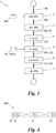
- FIG. 1 depicts a method 1 for validating (also referred to as “verifying” in the environment of hardware system development and testing) an electrical or electronic circuit (herein: a "hardware system”) HS.
- a model MO describes the hardware system HS in form of a netlist at register transfer level (“RTL").
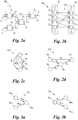
- the netlist is bipartite, i.e., it has cells C 1 , C 2 , ..., generally C i , and links L 1 , L 2 , ..., generally L k , (also known as “nets” or “wires”) between the cells C i , see Fig. 2a . No cells C i are immediately connected to other cells C i without intermediate links L k and no links L k are immediately connected to other links L k , see Fig. 2b .
- Fig. 2b illustrates the bipartite character on the basis of an exemplary sub-structure SS ( Fig. 2a ) of the model MO.
- the cells C 1 , C 2 , C 3 , C 4 of the sub-structure SS are concentrated in a first set S 1 on the left, where also further cells C i of the bipartite model MO would be concentrated (as symbolised by dots in Fig. 2b ), whereas the links L 1 , L 2 , L 3 , L 4 of the sub-structure SS are concentrated in a second set S 2 on the right of Fig. 2b , where also further links L k of the model MO would be concentrated (as symbolised by dots in Fig. 2b ).
- the interrelation between cells C i and links L k is symbolised by intermediate connections CO.
- the connections CO can be understood, e.g., as input-contacts I or output-contacts O ( Fig. 2a ) which connect cells C i and links L k of the sub-structure SS.
- cell C 1 is connected via its respective output-contact O to link L 1
- cell C 4 is connected via its respective input-contact I to link L 1 ; no other cells C i are connected to link L 1 as shown by the connections CO in Fig. 2b .
- a first step 2 of the method 1 for validating the hardware system HS one or (typically) more reference structures RS are provided.
- the provided reference structures RS are relevant for the validation, e.g., because they are prone to error or to possible manipulation by a designer and/or manufacturer of the hardware system HS.
- sub-structures SS are determined in the model MO.
- Each of the determined sub-structures SS comprises a subset of the cells C i and links L k of the model MO.
- structural equivalence may be determined on the level of the netlist model MO or on a further abstracted level of description of the hardware system HS.
- structural equivalence includes, e.g., isomorphism, on the one hand, but also more general structural comparability, on the other hand.
- input cones IN are extracted for each of the determined sub-structures SS from the model MO.
- Each input cone IN comprises control inputs, i.e., all control inputs in the model MO to one of the cells C i of the sub-structure SS.
- Each input cone IN reaches upstream, where necessary more than one upstream-level of a control path of the model MO, to a nearest register output in the model MO or to a nearest primary input, i.e., an input from outside to the model MO. In this way, an input cone IN is extracted for each cell C i in the sub-structure SS.
- a set of monopartite candidate graphs CG is created from the bipartite sub-structures SS. This is performed by mapping the cells C i and links L k of each sub-structure SS and of the respective input cones IN extracted for the sub-structure SS to nodes N 1 , N 2 , ..., generally N m , and edges E 1 , E 2 , ..., generally E p , of one of the candidate graphs CG of the set.
- Figs. 2a to 2d illustrate an example of such a mapping.
- This example is simplified in that it does not include the input cones IN to the cells C i of the sub-structure SS, and in that the shown sub-structure SS, for better visibility, has merely four cells C 1 , C 2 , C 3 , C 4 and four links L 1 , L 2 , L 3 , L 4 .
- Fig. 2a shows, in dashed lines, further links L' from and to the rest of the model MO (not depicted in Fig. 2a ) outside the sub-structure SS.
- Figs. 2c and 2d show two different representations of a monopartite candidate graph CG which was mapped from the sub-structure SS of Figs. 2a and 2b (in this exemplary illustration: without input cones IN).
- the nodes N 1 , N 2 , N 3 , N 4 have node types, which are differentiated, in the example of Figs. 2c and 2d , by lines identifying the nodes N 1 , N 2 , N 3 , N 4 :
- solid lines and dashed lines symbolise a first and a second node type, respectively; in general, the candidate graphs CG may have node types from a set of dozens or even hundreds of different node types as necessary.
- a node type includes the type of a cell C i mapped to the node N m , e.g., the cell C i may be a logical AND, OR etc.; moreover, the node type may be another parameter of the cell C i , e.g., the bit width or the like; furthermore, the node type may comprise parameters of the links L k between the respective cell C i and its neighbours, etc., or user defined attributes of the node.
- a node type may even comprise more than one such parameter, in a combination and/or in two or more dimensions, i.e., the node type is optionally multi-dimensional.
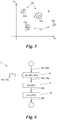
- a separate n-dimensional match vector MV ( Fig. 4 ) is created for each candidate graph CG that was created in step 4.
- a number of n graphlets GL one for each dimension D 1 , D 2 , ..., D n , generally D t , of the match vector MV, was predetermined.
- Each graphlet GL has nodes N G1 , N G2 , ..., generally N Gq , and edges E G1 , E G2 , ..., generally E Gr , and each node N Gq has a node type, see Figs. 3a and 3b .
- the graphlets GL differ from each other in the node types, in the number of nodes N Gq or edges E Gr , and/or in their combination, i.e., in the structure of the graphlets GL. While some graphlets GL may have two nodes N Gq , others may have three or more nodes N Gq. However, the number of nodes N Gq in the graphlets GL is generally lower or even substantially lower than the number of nodes N m in typical candidate graphs CG.
- Figs. 3a and 3b show two different examples of graphlets GL, both of which have three nodes N Gq .
- the nodes N Gq and edges E Gr of the graphlet GL in the example of Fig. 3a form a 2-to-1 coalescence, whereas the nodes N Gq and edges E Gr of the graphlet GL in the example of Fig. 3b form a 1-to-2 bifurcation.
- two different node types of the graphlets GL shown in Figs. 3a and 3b are symbolised by solid lines and dashed lines, respectively. It shall be understood that, like the candidate graphs CG, also the graphlets GL may have nodes N Gq of more than two different types, e.g., a subset of a set of dozens or even hundreds of node types.
- each match vector MV is created in step 5 of the method 1 by counting the occurrences of each of the predetermined graphlets GL in the candidate graph CG the respective match vector MV is created for, and by filling each count x 1 , x 2 , ..., x n , generally x t , of occurrence in a different one of the dimensions D t (here: fields) of the match vector MV.
- each dimension D t of the match vector MV created for a respective candidate graph CG comprises the count x t of occurrences, in the candidate graph CG, of a different one of the predefined graphlets GL.
- the match vector MV is two-dimensional, one dimension D t for each graphlet GL of Figs. 3a and 3b , respectively.
- candidate graphs CG and match vectors MV may be created by the method 1; moreover, the number n of predetermined graphlets GL and, hence, the n dimensions D t of each match vector MV may be up to a few dozen or even a few hundred.
- a fixed number n of graphlets GL may have been provided - and thereby be predetermined - for step 5.
- a set T of graphlets GL may generally be provided for the method 1 and each graphlet GL of the set T is matched with all candidate graphs CG.
- only such graphlets GL of the set T are predetermined for step 5, for which graphlets GL a match is found in at least one of the candidate graphs CG.
- n is the number of graphlets GL of the set T for which a match was found.
- the candidate graphs CG are clustered in clusters CL ( Fig. 5 ) on the basis of similarity of the created match vectors MV.
- a multitude of techniques to determine the similarity between vectors is known in the art and may be applied to the match vectors MV.
- a principal component analysis is applied to the created match vectors MV.
- the number n of dimensions D t of the match vectors MV can be significantly reduced in step 6, e.g., to only two dimensions D 1 , D 2 as shown in Fig. 5 , even when the original dimensionality was materially higher. Thereby, the determination of the similarity of the match vectors MV is facilitated.
- the step 6 of clustering the candidate graphs CG is performed using a density-based clustering algorithm, e.g., using the density-based algorithm known as "OPTICS" in the art.
- the clustering of step 6 results in the candidate graphs CG being scattered over a (here: two-dimensional; in other cases: multi-dimensional) area A spanned by the dimensions D t of the match vector MV.
- a candidate graph CG which has a match vector MV that is similar to the match vector MV of another candidate graph CG is closer to said other candidate graph CG than to a further candidate graph CG having a dissimilar match vector MV.
- candidate graphs CG lying side by side in the area A are clustered in the clusters CL.
- Candidate graphs CG of the same cluster CL indicate similar structural composition and, hence, comparable functional behaviour of the sub-structures SS, from which these candidate graphs CG were mapped.
- a subsequent validation step 7 it is therefore sufficient to select only one candidate graph CG of each cluster CL and determine the functional behaviour of the respective sub-structure SS said candidate graph CG was mapped from.
- the hardware system HS is not validated.
- the functional behaviour of this sub-structure SS is valid, further candidate graphs CG of the same cluster CL need not be selected. The same is repeated for one candidate graph CG of each of at least some of the remaining clusters CL until either an invalid functional behaviour of a respective sub-structure SS is determined or until the functional behaviour of the respective sub-structure SS of the selected candidate graph CG of each further cluster CL is valid. In the latter case, the hardware system HS is validated.
- Some clusters CL may be omitted in step 7, e.g., because they are located in a specific part, for example a remote part of the area A, such that there are good reasons to reliably expect that the behaviours of the respective sub-structures SS of candidate graphs CG in those clusters CL are valid.
- step 2 the structural equivalence may be determined in step 2 on a level of description of the hardware system HS which is further abstracted from the netlist model MO.
- Fig. 6 depicts one example of such an abstraction of the hardware system's HS description. However, other examples are known to the skilled person.
- said step 2 of determining sub-structures SS in the model MO comprises, in essence, three sub-steps 8 to 10:
- the first sub-step 8 relates to mapping the cells C i and links L k of the whole model MO to nodes N m and edges E p of a monopartite model graph MG, wherein each node N m has a node type.
- mapping was exemplified with reference to Figs. 2a to 2d above.
- the cells C i and links L k of each of the provided reference structures RS are mapped to nodes N m and edges E p of a monopartite reference graph RG, wherein each node N m has a node type.
- sub-graphs SG are searched and found in the model graph MG, wherein each sub-graph SG matches one of said reference graphs RG. Thereafter, in the sub-step 10, the respective sub-structure SS for each of said found sub-graphs SG is determined in the model MO by re-mapping the sub-graph SG back to the model MO, i.e., by finding the respective sub-structure SS the sub-graph SG was mapped from.
Landscapes
- Engineering & Computer Science (AREA)
- Computer Hardware Design (AREA)
- Physics & Mathematics (AREA)
- Theoretical Computer Science (AREA)
- Evolutionary Computation (AREA)
- Geometry (AREA)
- General Engineering & Computer Science (AREA)
- General Physics & Mathematics (AREA)
- Design And Manufacture Of Integrated Circuits (AREA)
- Information Retrieval, Db Structures And Fs Structures Therefor (AREA)
Priority Applications (4)
| Application Number | Priority Date | Filing Date | Title |
|---|---|---|---|
| EP18214502.9A EP3671490A1 (fr) | 2018-12-20 | 2018-12-20 | Procédé de validation d'un système hardware |
| US17/415,404 US11645439B2 (en) | 2018-12-20 | 2019-12-11 | Method for validating a hardware system |
| PCT/EP2019/084549 WO2020126718A1 (fr) | 2018-12-20 | 2019-12-11 | Procédé de validation d'un système matériel |
| EP19813896.8A EP3899775A1 (fr) | 2018-12-20 | 2019-12-11 | Procédé de validation d'un système matériel |
Applications Claiming Priority (1)
| Application Number | Priority Date | Filing Date | Title |
|---|---|---|---|
| EP18214502.9A EP3671490A1 (fr) | 2018-12-20 | 2018-12-20 | Procédé de validation d'un système hardware |
Publications (1)
| Publication Number | Publication Date |
|---|---|
| EP3671490A1 true EP3671490A1 (fr) | 2020-06-24 |
Family
ID=64746380
Family Applications (2)
| Application Number | Title | Priority Date | Filing Date |
|---|---|---|---|
| EP18214502.9A Withdrawn EP3671490A1 (fr) | 2018-12-20 | 2018-12-20 | Procédé de validation d'un système hardware |
| EP19813896.8A Withdrawn EP3899775A1 (fr) | 2018-12-20 | 2019-12-11 | Procédé de validation d'un système matériel |
Family Applications After (1)
| Application Number | Title | Priority Date | Filing Date |
|---|---|---|---|
| EP19813896.8A Withdrawn EP3899775A1 (fr) | 2018-12-20 | 2019-12-11 | Procédé de validation d'un système matériel |
Country Status (3)
| Country | Link |
|---|---|
| US (1) | US11645439B2 (fr) |
| EP (2) | EP3671490A1 (fr) |
| WO (1) | WO2020126718A1 (fr) |
Families Citing this family (1)
| Publication number | Priority date | Publication date | Assignee | Title |
|---|---|---|---|---|
| EP3671490A1 (fr) * | 2018-12-20 | 2020-06-24 | Technische Universität Wien | Procédé de validation d'un système hardware |
Citations (1)
| Publication number | Priority date | Publication date | Assignee | Title |
|---|---|---|---|---|
| US20150100929A1 (en) * | 2013-10-07 | 2015-04-09 | Raytheon Company | Reverse synthesis of digital netlists |
Family Cites Families (5)
| Publication number | Priority date | Publication date | Assignee | Title |
|---|---|---|---|---|
| AU2003260047A1 (en) * | 2002-08-29 | 2004-03-19 | Paul Rudolf | Associative memory device and method based on wave propagation |
| US20080270332A1 (en) * | 2003-08-26 | 2008-10-30 | Paul Rudolf | Associative Memory Device and Method Based on Wave Propagation |
| CA2953385C (fr) * | 2014-06-30 | 2024-07-02 | Evolving Machine Intelligence Pty Ltd | Systeme et procede pour modeliser un comportement de systeme |
| EP3671490A1 (fr) * | 2018-12-20 | 2020-06-24 | Technische Universität Wien | Procédé de validation d'un système hardware |
| US12067006B2 (en) * | 2020-06-23 | 2024-08-20 | SoundHound AI IP, LLC. | Machine learning system for digital assistants |
-
2018
- 2018-12-20 EP EP18214502.9A patent/EP3671490A1/fr not_active Withdrawn
-
2019
- 2019-12-11 US US17/415,404 patent/US11645439B2/en active Active
- 2019-12-11 EP EP19813896.8A patent/EP3899775A1/fr not_active Withdrawn
- 2019-12-11 WO PCT/EP2019/084549 patent/WO2020126718A1/fr not_active Ceased
Patent Citations (1)
| Publication number | Priority date | Publication date | Assignee | Title |
|---|---|---|---|---|
| US20150100929A1 (en) * | 2013-10-07 | 2015-04-09 | Raytheon Company | Reverse synthesis of digital netlists |
Non-Patent Citations (3)
| Title |
|---|
| DEMROZI FLORENC ET AL: "Exploiting sub-graph isomorphism and probabilistic neural networks for the detection of hardware Trojans at RTL", 2017 IEEE INTERNATIONAL HIGH LEVEL DESIGN VALIDATION AND TEST WORKSHOP (HLDVT), IEEE, 5 October 2017 (2017-10-05), pages 67 - 73, XP033276939, DOI: 10.1109/HLDVT.2017.8167465 * |
| F. DEMROZI ET AL.: "Exploiting Sub-Graph Isomorphism and Probabilistic Neural Networks for the Detection of Hardware Trojans at RTL", 2017 IEEE INTERNATIONAL HIGH LEVEL DESIGN VALIDATION AND TEST WORKSHOP (HLDVT, 2017, pages 67 - 73, XP033276939, DOI: doi:10.1109/HLDVT.2017.8167465 |
| LUCA PICCOLBONI ET AL: "Efficient Control-Flow Subgraph Matching for Detecting Hardware Trojans in RTL Models", ACM TRANSACTIONS ON EMBEDDED COMPUTING SYSTEMS., vol. 16, no. 5s, 27 September 2017 (2017-09-27), US, pages 1 - 19, XP055597687, ISSN: 1539-9087, DOI: 10.1145/3126552 * |
Also Published As
| Publication number | Publication date |
|---|---|
| US20220067252A1 (en) | 2022-03-03 |
| US11645439B2 (en) | 2023-05-09 |
| WO2020126718A1 (fr) | 2020-06-25 |
| EP3899775A1 (fr) | 2021-10-27 |
Similar Documents
| Publication | Publication Date | Title |
|---|---|---|
| US20250094396A1 (en) | Automatic entity resolution with rules detection and generation system | |
| US8446842B2 (en) | Method and apparatus for identifying similar sub-graphs in a network | |
| US10902025B2 (en) | Techniques for measuring a property of interest in a dataset of location samples | |
| US7451375B2 (en) | Directed falsification of a circuit | |
| US8176050B2 (en) | Method and apparatus of supporting creation of classification rules | |
| CN110443159A (zh) | 数字识别方法、装置、电子设备及存储介质 | |
| US11055210B2 (en) | Software test equipment and software testing method | |
| US20080240504A1 (en) | Integrating Object Detectors | |
| CN113935034B (zh) | 基于图神经网络的恶意代码家族分类方法、装置和存储介质 | |
| US20210406693A1 (en) | Data sample analysis in a dataset for a machine learning model | |
| CN109102159A (zh) | 旅客评级模型生成方法、装置、计算机设备和存储介质 | |
| Touli et al. | Fpt-algorithms for computing gromov-hausdorff and interleaving distances between trees | |
| US11645439B2 (en) | Method for validating a hardware system | |
| Picek et al. | When theory meets practice: A framework for robust profiled side-channel analysis | |
| CN106569944B (zh) | 基于约束树的星载软件测试数据分析方法 | |
| US20040237057A1 (en) | Performing latch mapping of sequential circuits | |
| Wilkins et al. | COUGAR: clustering of unknown malware using genetic algorithm routines | |
| CN119441059A (zh) | 测试用例优先级排序方法、装置、电子设备及可读存储介质 | |
| Ferreira et al. | Density-based core support extraction for non-stationary environments with extreme verification latency | |
| Weber et al. | Analysis of Graph-based Partitioning Algorithms and Partitioning Metrics for Hardware Reverse Engineering | |
| Guénoche | Clustering by vertex density in a graph | |
| KR20150124825A (ko) | 화상분류 기반의 나이브 베이즈 분류기 | |
| Parvin et al. | Nearest cluster classifier | |
| Andrae et al. | Soft clustering analysis of galaxy morphologies: a worked example with SDSS | |
| Bazell et al. | Class discovery in galaxy classification |
Legal Events
| Date | Code | Title | Description |
|---|---|---|---|
| PUAI | Public reference made under article 153(3) epc to a published international application that has entered the european phase |
Free format text: ORIGINAL CODE: 0009012 |
|
| STAA | Information on the status of an ep patent application or granted ep patent |
Free format text: STATUS: THE APPLICATION HAS BEEN PUBLISHED |
|
| AK | Designated contracting states |
Kind code of ref document: A1 Designated state(s): AL AT BE BG CH CY CZ DE DK EE ES FI FR GB GR HR HU IE IS IT LI LT LU LV MC MK MT NL NO PL PT RO RS SE SI SK SM TR |
|
| AX | Request for extension of the european patent |
Extension state: BA ME |
|
| STAA | Information on the status of an ep patent application or granted ep patent |
Free format text: STATUS: THE APPLICATION IS DEEMED TO BE WITHDRAWN |
|
| 18D | Application deemed to be withdrawn |
Effective date: 20210112 |