EP3671643B1 - Procédé et appareil pour étalonner le paramètre extrinsèque d'un capteur d'images - Google Patents
Procédé et appareil pour étalonner le paramètre extrinsèque d'un capteur d'images Download PDFInfo
- Publication number
- EP3671643B1 EP3671643B1 EP19217696.4A EP19217696A EP3671643B1 EP 3671643 B1 EP3671643 B1 EP 3671643B1 EP 19217696 A EP19217696 A EP 19217696A EP 3671643 B1 EP3671643 B1 EP 3671643B1
- Authority
- EP
- European Patent Office
- Prior art keywords
- parallel
- feature edges
- image
- points
- image sensor
- Prior art date
- Legal status (The legal status is an assumption and is not a legal conclusion. Google has not performed a legal analysis and makes no representation as to the accuracy of the status listed.)
- Active
Links
Images


Classifications
-
- G—PHYSICS
- G01—MEASURING; TESTING
- G01B—MEASURING LENGTH, THICKNESS OR SIMILAR LINEAR DIMENSIONS; MEASURING ANGLES; MEASURING AREAS; MEASURING IRREGULARITIES OF SURFACES OR CONTOURS
- G01B11/00—Measuring arrangements characterised by the use of optical techniques
- G01B11/26—Measuring arrangements characterised by the use of optical techniques for measuring angles or tapers; for testing the alignment of axes
-
- G—PHYSICS
- G06—COMPUTING OR CALCULATING; COUNTING
- G06T—IMAGE DATA PROCESSING OR GENERATION, IN GENERAL
- G06T7/00—Image analysis
- G06T7/70—Determining position or orientation of objects or cameras
- G06T7/73—Determining position or orientation of objects or cameras using feature-based methods
-
- G—PHYSICS
- G06—COMPUTING OR CALCULATING; COUNTING
- G06T—IMAGE DATA PROCESSING OR GENERATION, IN GENERAL
- G06T7/00—Image analysis
- G06T7/10—Segmentation; Edge detection
- G06T7/13—Edge detection
-
- G—PHYSICS
- G06—COMPUTING OR CALCULATING; COUNTING
- G06T—IMAGE DATA PROCESSING OR GENERATION, IN GENERAL
- G06T7/00—Image analysis
- G06T7/50—Depth or shape recovery
- G06T7/536—Depth or shape recovery from perspective effects, e.g. by using vanishing points
-
- G—PHYSICS
- G06—COMPUTING OR CALCULATING; COUNTING
- G06T—IMAGE DATA PROCESSING OR GENERATION, IN GENERAL
- G06T7/00—Image analysis
- G06T7/80—Analysis of captured images to determine intrinsic or extrinsic camera parameters, i.e. camera calibration
-
- H—ELECTRICITY
- H04—ELECTRIC COMMUNICATION TECHNIQUE
- H04N—PICTORIAL COMMUNICATION, e.g. TELEVISION
- H04N23/00—Cameras or camera modules comprising electronic image sensors; Control thereof
- H04N23/50—Constructional details
- H04N23/54—Mounting of pick-up tubes, electronic image sensors, deviation or focusing coils
-
- H—ELECTRICITY
- H04—ELECTRIC COMMUNICATION TECHNIQUE
- H04N—PICTORIAL COMMUNICATION, e.g. TELEVISION
- H04N23/00—Cameras or camera modules comprising electronic image sensors; Control thereof
- H04N23/60—Control of cameras or camera modules
- H04N23/698—Control of cameras or camera modules for achieving an enlarged field of view, e.g. panoramic image capture
-
- G—PHYSICS
- G06—COMPUTING OR CALCULATING; COUNTING
- G06T—IMAGE DATA PROCESSING OR GENERATION, IN GENERAL
- G06T2207/00—Indexing scheme for image analysis or image enhancement
- G06T2207/30—Subject of image; Context of image processing
- G06T2207/30244—Camera pose
-
- G—PHYSICS
- G06—COMPUTING OR CALCULATING; COUNTING
- G06T—IMAGE DATA PROCESSING OR GENERATION, IN GENERAL
- G06T2207/00—Indexing scheme for image analysis or image enhancement
- G06T2207/30—Subject of image; Context of image processing
- G06T2207/30248—Vehicle exterior or interior
- G06T2207/30252—Vehicle exterior; Vicinity of vehicle
- G06T2207/30256—Lane; Road marking
Definitions
- An example is the surround view system which often includes four wide angle vision-based sensors mounted externally at the front, rear and sides of the vehicle.
- the image sensors in a surround view system typically have a horizontal field of view that is more than 180 degrees.
- a 360-degree view of a vehicle's environment is obtained by stitching together images from the surround view image sensors.
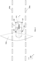
- the machine vision module may rely on information from other operations such as lane keeping function for information on the location of lane markings in an image. After identifying potential first set of parallel features, the process may check if these potential feature edges are parallel. In some implementations, parallelism may be inferred by looking the vehicle's direction of travel when the sample image was recorded. For instance, if a pair of lane markings are used as calibration structures, they may be assumed to be parallel in an image frame if the steering angle and/or wheel angle is close to zero (e.g. 0.2 degrees or less) when the image frame was captured. The steering angle and wheel angle of the vehicle may be obtained from a steering angle sensor 164 and a wheel angle sensor 166 respectively. Using the scenario in FIG.
- a calibration structure in the form of a first set of parallel feature edges is selected.
- the first set of parallel feature edges comprises at least two feature edges which are parallel to each other. The actual number of parallel feature edges required may vary depending on the number of parallel features required to determine reference vanishing points for the type of image sensor being calibrated.
- image sensors which can be modelled using the sphere camera model including central catadioptic systems using fisheye lenses only require two parallel feature edges in order to determine reference vanishing points which can be used for calibration.
- One or more calibration structure selection criteria may be used to decide between two or more sets of feature edges which are suitable to be used as calibration structures. For example, characteristics tied to the image quality of the feature edges may be used.
- the image of the selected first set of parallel feature edges may be subjected to image processing steps configured to improve the sharpness of feature edges. For example, the processing may suppress spurious edges by performing a connected component analysis and Random Sample Consensus (RANSAC) algorithm may be used to filter out erroneous image points which do not form part of the feature edges in the set.
- RANSAC Random Sample Consensus
- the process then goes on to determine reference vanishing points for the first set of parallel feature edges in block 320.
- the reference vanishing points being located on a projection reference frame.
- the projection reference frame may refer to the 2-dimensional image plane which appears in an image frame or any intermediate projection reference frame involved in the course of projecting a 3-dimensional point in the real world to the 2-dimensional image plane.
- the mapping of 3-dimensional points in the real world to a 2-dimensional image involves two projection steps. The first is a projection of the 3-dimensional point to a point on a unitary sphere and a second is a perspective projection from the unitary sphere to the image plane of the sensor. In this case, both the unitary sphere and image plane may function as projection reference frames.
- FIG. 4A shows an exemplary real-life view of a first set of parallel feature edges 410 comprising a pair of parallel longitudinal feature edges (410a, 410b).
- the longitudinal features form part of two parallel tracks of lane markings such as the lane markings 240a and 240b illustrated in FIG. 2 .
- FIG. 4B is the corresponding image 420 of the first set of parallel feature edges in FIG. 4A when captured by an image sensor which can be modelled using the sphere camera model such as image sensors using fisheye lenses. It is known that for image sensors based on the sphere camera model, straight lines in the real world are projected in the image plane as conic curves which can be approximated as part of a circle due to non-linear distortion. This is illustrated in FIG. 4B where the straight-line first and second feature edges in FIG. 4A (410a, 410b) are projected as conic curves (420a, 420b) in the fisheye image plane.
- a first circle (520a) is fitted to the image of first feature edge (420a) and a second circle (520b) is fitted to the image of the second feature edge (420b).
- Images of the first and second feature edges are shown as white curves in FIG. 5 .
- the radius and centre of the respective circles are chosen such that most of the image points for each feature edge lie on the circle.
- a minimum threshold percentage of image points may be set for this purpose.
- the circles may be fitted such that 95% percent or more of the image points from the feature edges (e.g. 420a, 420b in FIG. 4B ) fall on the circle.
- a gradient descent approach may be used to find a circle which best fits the maximum number of image points.
- a Lose function (L) is calculated using equation (1). The same is repeated iteratively by varying the location of the centre of the circle and its radius until we obtain a circle with a centre and radius which minimises or reduces the error function (which is the Lose function (L) in this example) such that it is within a threshold limit.
- the threshold limit may be defined based on a threshold percentage of image points that should lie on the circle. It will be appreciated by a person skilled in the art that apart from the lose function, other formulas for fitting a circle may also be suitable.
- FIG. 5 illustrates an example where a first and second circle (520a, 520b) are fitted to the image points of the first and second feature edges (420a, 420b) respectively.
- reference vanishing points for the first set of parallel feature edges may be derived by determining where the first and second circles intersect. For example, in the FIG. 4-5 illustration, the vanishing points are located at the points indicated by reference numerals 540 and 560.
- FIG. 6 illustrates an exemplary method of selecting virtual feature edges for the second set of parallel feature edges.
- a road surface or ground plane 610 comprising a first set of parallel feature edges in the form of 2 parallel lane markings (620, 640) is shown.
- the image sensor is mounted on a vehicle 660 with a vehicle co-ordinate system comprising an x-axis extending along the longitudinal axis of the vehicle, a y-axis extending along a lateral axis of the vehicle such as the axle joining two side wheels and a z-axis extending out of the plane of the paper perpendicular to the x and y axis.
- the real world co-ordinates of two or more points on at least one of the lane markings (e.g. 620) with respect to the vehicle co-ordinate system is derived from the image frame.
- a second set of parallel feature edges located on the ground plane 610 and parallel to the lane markings (620, 640) may be derived by shifting the co-ordinates of points on at least one of the lane markings (e.g. 620) along the y-axis of the vehicle.
- a third feature edge belonging to the second set of parallel edges may be obtained by shifting the points 620a and 620b along the y axis of the vehicle co-ordinate system.
- the lane markings (620, 640) will be parallel to the x-axis of the vehicle co-ordinate system. Accordingly, by moving along the y-axis of the vehicle co-ordinate system while maintaining the x and z co-ordinates constant, points passing through a line parallel to the first lane marking 620 may be obtained. Applying this principle to the FIG.
- the third feature edge 670 parallel to the lane marking 620 passes through points 670a and 670b.
- the points 680a and 680b may be obtained by displacing the points 620a and 620b along the y axis of the vehicle co-ordinate system.
- the method goes on to block 340 where the processor projects a plurality of points from the second set parallel feature edges onto a projection reference frame of the image sensor based on a pre-existing projection matrix of the image sensor.
- Known modelling software such as Cam2 algorithm may be used for this purpose. Since the objective here is to check for any deviation between the vanishing points for the second set of parallel feature edges and the reference vanishing points, the projection reference frame where points from the second set parallel feature edges would be the same as the one where the reference vanishing points are derived with respect to. For instance, in the FIG. 4-5 example, the reference vanishing points were derived in block 320 was with respect to the image plane.
- points from the second set parallel feature edges will also be projected onto the image plane in block 340 so that second vanishing points on the image plane may be determined.
- the projection matrix of an image sensor is generally expressed in terms of an image sensor's intrinsic and extrinsic parameters. If this is the first round of projection onto the projection reference frame, a pre-existing projection matrix based on the last known intrinsic and extrinsic parameters is used for projecting the second set of parallel feature edges.
- a pre-existing projection matrix based on the last known intrinsic and extrinsic parameters is used for projecting the second set of parallel feature edges.
- projecting a plurality of points from the second set parallel feature edges onto the image plane of the image sensor results in images of the third and fourth feature edges (770, 780) appearing as conic curves which can be approximated as part of a circle (see FIG. 7 ).
- FIG. 7 shows a third circle 775 and a fourth circle 785 obtained by fitting to the image points of the third and fourth feature edges (770, 780) respectively. Since the third and fourth feature edges are parallel, the third and fourth circles intersect at points 790 and 792 which correspond to the vanishing points for the second set of parallel feature edges on the image plane (that is, the second vanishing points) .
- the second vanishing points may similarly be obtained by solving circular equations similar to those for deriving the reference vanishing points in block 320.
- the method checks for variations of the second vanishing points from the reference vanishing points in block 360. Based on the vanishing point concepts discussed earlier, the vanishing points for the first and second set of parallel features should coincide since their feature edges are all parallel to each other in the rea world. However, if there is an error in the projection matrix used for projecting points from the second set parallel feature edges onto a projection reference frame, the second set of parallel feature edges will no longer be parallel to the first set in the image plane or any other projection reference frame being used. Accordingly, the second vanishing points will not coincide with the reference vanishing points. For example, in FIG.
- the second vanishing points (790, 792) derived in block 350 by projecting points from the second set parallel feature edges and the reference vanishing points (540, 560) derived in block 330 do not coincide even though the second set of parallel feature edges have been selected such that in the real world context the first and second set of parallel feature edges are parallel to each other.
- Such deviation in vanishing point location is indicative of an error in the pre-existing projection matrix.
- the method then goes on to decision block 370 which checks if any deviation in the location of the second vanishing points from that of the reference vanishing points is within acceptable predefined limits.
- step 380 the pre-existing projection matrix is modified by adjusting one or more of the extrinsic parameters before going back to block 340 and repeating blocks 340-360 until any deviation in the location of the second vanishing points is within acceptable predefined limits.
- the assumption here is that any error in the projection matrix is attributed to a shift in one or more extrinsic parameters instead of the intrinsic parameter values such as focal length, optical centre.
- the process goes to block 390.
- the process of reducing variations between the reference and second vanishing points may comprise drawing a first connecting line (R) joining the reference vanishing points (540, 560) and a second connecting line (S) joining the second vanishing points (790, 792).
- R first connecting line
- S second connecting line
Landscapes
- Engineering & Computer Science (AREA)
- Physics & Mathematics (AREA)
- General Physics & Mathematics (AREA)
- Computer Vision & Pattern Recognition (AREA)
- Theoretical Computer Science (AREA)
- Multimedia (AREA)
- Signal Processing (AREA)
- Image Analysis (AREA)
- Studio Devices (AREA)
- Traffic Control Systems (AREA)
- Image Processing (AREA)
Claims (19)
- Procédé mis en œuvre par ordinateur pour l'étalonnage d'un ou plusieurs paramètres extrinsèques d'un capteur d'image, comprenant :la sélection d'un premier ensemble d'arêtes caractéristiques parallèles apparaissant dans une image capturée par le capteur d'images, le premier ensemble d'arêtes caractéristiques parallèles correspondant à un premier ensemble d'arêtes caractéristiques parallèles de la vie réelle ;la détermination de points de fuite de référence pour le premier ensemble d'arêtes caractéristiques parallèles, les points de fuite de référence étant situés sur une image de référence de projection du capteur d'image ;la sélection d'un deuxième ensemble d'arêtes caractéristiques parallèles qui sont parallèles au premier ensemble d'arêtes caractéristiques parallèles dans les coordonnées du monde réel ;la projection d'une pluralité de points du deuxième ensemble d'arêtes caractéristiques parallèles sur l'image de référence de projection selon une matrice de projection pré-existante du capteur d'image ;la détermination, pour le deuxième ensemble d'arêtes caractéristiques parallèles, de deuxièmes points de fuite situés sur l'image de référence de projection ; etla réduction de tout écart de localisation des deuxièmes points de fuite par rapport aux points de fuite de référence jusqu'à ce que l'écart se trouve dans une ou plusieurs limites prédéfinies par exécution récursive d'au moins les étapes suivantes :la modification de la matrice de projection pré-existante par ajustement d'un ou plusieurs des paramètres extrinsèques ;la projection d'une pluralité de points du deuxième ensemble d'arêtes caractéristiques parallèles sur l'image de référence de projection en utilisant la matrice de projection pré-existante modifiée ; etla détermination des deuxièmes points de fuite après la projection.
- Procédé selon la revendication 1, dans lequel le capteur d'image est un capteur qui peut être modélisé à l'aide du modèle de caméra sphérique.
- Procédé selon la revendication 2, dans lequel l'image de référence de projection du capteur d'image est le plan image du capteur d'image et la détermination de la première paire de points de fuite de référence pour le premier ensemble de caractéristiques parallèles comprend :
l'ajustement d'un premier cercle et d'un deuxième cercle aux points images d'une première et d'une deuxième arêtes caractéristiques du premier ensemble d'arêtes parallèles et la détermination des endroits où se croisent les premier et deuxième cercles. - Procédé selon la revendication 3, dans lequel la détermination des deuxièmes points de fuite pour le deuxième ensemble d'arêtes caractéristiques parallèles comprend :l'ajustement d'un troisième cercle et d'un quatrième cercle aux points images d'une troisième et d'une quatrième arêtes caractéristiques du deuxième ensemble d'arêtes parallèles obtenu par projection d'une pluralité de points des troisième et quatrième arêtes caractéristiques du deuxième ensemble d'arêtes caractéristiques parallèles sur le plan image selon une matrice de projection pré-existante du capteur d'image ; etla détermination des endroits où se croisent les troisième et quatrième cercles.
- Procédé selon la revendication 3 ou 4, dans lequel l'ajustement d'au moins les premier, deuxième, troisième ou quatrième cercles est basé sur la minimisation d'une fonction de perte.
- Procédé selon l'une quelconque des revendications 2 à 5, dans lequel la réduction de tout écart de localisation des deuxièmes points de fuite par rapport aux points de fuite de référence jusqu'à ce que l'écart se trouve dans les une ou plusieurs limites prédéfinies comprend :le dessin d'une première ligne de connexion reliant les points de fuite de référence ; etle dessin d'une deuxième ligne de connexion reliant les deuxièmes points de fuite.
- Procédé selon la revendication 6, dans lequel la modification de la matrice de projection pré-existante par ajustement d'un ou plusieurs des paramètres extrinsèques comprend l'ajustement initial des un ou plusieurs des paramètres extrinsèques pour réduire tout écart de gradient entre les deuxième et première lignes de connexion jusqu'à ce que l'écart de gradient se trouve dans une limite de gradient avant l'ajustement des un ou plusieurs paramètres extrinsèques pour réduire tout écart de localisation ou de longueur de la deuxième ligne de connexion par rapport à la première de ligne de connexion.
- Procédé selon la revendication 7, dans lequel :
l'ajustement initial des un ou plusieurs des paramètres extrinsèques pour réduire l'écart de gradient entre les deuxième et première lignes de connexion jusqu'à ce que l'écart de gradient se trouve dans une limite de gradient comprend un ajustement d'un ou plusieurs des paramètres extrinsèques en lien avec une orientation. - Procédé selon l'une quelconque des revendications 7 ou 8, dans lequel :
l'ajustement des un ou plusieurs paramètres extrinsèques pour réduire tout écart de localisation et/ou de longueur des première et deuxième lignes de connexion comprend un ajustement d'un ou plusieurs des paramètres extrinsèques en lien avec une translation. - Procédé selon la revendication 2, dans lequel l'image de référence de projection est une sphère unitaire.
- Procédé selon l'une quelconque des revendications précédentes, dans lequel le capteur d'image est monté sur un véhicule et la sélection d'un premier ensemble d'arêtes caractéristiques parallèles comprend :la détection d'au moins deux arêtes caractéristiques dans l'image ; etla détermination du fait que les arêtes caractéristiques sont ou non parallèles par vérification d'au moins un angle de braquage ou angle de roue du véhicule lorsque l'image a été capturée.
- Procédé selon l'une quelconque des revendications précédentes, dans lequel le capteur d'image est monté sur un véhicule et le deuxième ensemble d'arêtes caractéristiques parallèles est obtenu par décalage du premier ensemble d'arêtes caractéristiques parallèles le long d'un axe de coordonnées du véhicule situé le long d'un axe latéral du véhicule.
- Procédé selon l'une quelconque des revendications précédentes, dans lequel les arêtes de caractéristiques parallèles du deuxième ensemble sont des arêtes caractéristiques virtuelles.
- Dispositif pour l'étalonnage d'un ou plusieurs paramètres extrinsèques d'un capteur d'image, comprenant :un processeur ;au moins une mémoire couplée au processeur et stockant des instructions exécutables par le processeur amenant le processeur à :sélectionner un premier ensemble d'arêtes caractéristiques parallèles apparaissant dans une image capturée par le capteur d'images, le premier ensemble d'arêtes caractéristiques parallèles représentant un premier ensemble d'arêtes caractéristiques parallèles de la vie réelle ;déterminer des points de fuite de référence pour le premier ensemble d'arêtes caractéristiques parallèles, les points de fuite de référence étant situés sur une image de référence de projection du capteur d'image ;sélectionner un deuxième ensemble d'arêtes caractéristiques parallèles qui sont parallèles au premier ensemble d'arêtes caractéristiques parallèles dans les coordonnées du monde réel ;projeter une pluralité de points du deuxième ensemble d'arêtes caractéristiques parallèles sur l'image de référence de projection selon une matrice de projection pré-existante du capteur d'image ;déterminer, pour le deuxième ensemble d'arêtes caractéristiques parallèles, des deuxièmes points de fuite situés sur l'image de référence de projection ; etréduire tout écart de localisation des deuxièmes points de fuite par rapport aux points de fuite de référence jusqu'à ce que l'écart se trouve dans une ou plusieurs limites prédéfinies par exécution récursive d'au moins les étapes suivantes :modification de la matrice de projection pré-existante par ajustement d'un ou plusieurs des paramètres extrinsèques ;projection d'une pluralité de points du deuxième ensemble d'arêtes caractéristiques parallèles sur l'image de référence de projection en utilisant la matrice de projection pré-existante modifiée ; etdétermination des deuxièmes points de fuite après la projection.
- Dispositif selon la revendication 14, dans lequel le capteur d'image est un capteur qui peut être modélisé par le modèle de caméra sphérique, l'image de référence de projection étant le plan image du capteur d'image et l'au moins une mémoire amenant le processeur à :déterminer les points de fuite de référence par ajustement d'un premier cercle et d'un deuxième cercle aux points images d'une première et d'une deuxième arête caractéristique du premier ensemble d'arêtes parallèles, les points de fuite de référence étant situés aux endroits où les premier et deuxième cercles se croisent ;déterminer les deuxièmes points de fuite en ajustant un troisième cercle et un quatrième cercle aux points images d'une troisième et d'une quatrième arête caractéristique du deuxième ensemble d'arêtes parallèles obtenu par projection d'une pluralité de points des troisième et quatrième arêtes caractéristiques sur le plan image du capteur d'image, les deuxièmes points de fuite étant situés aux endroits où les troisième et quatrième cercles se croisent.
- Dispositif selon les revendications 14 ou 15, dans lequel le capteur d'image est monté sur un véhicule et l'au moins une mémoire amène le processeur à sélectionner un premier ensemble d'arêtes caractéristiques parallèles par au moins les étapes suivantes :
détection d'au moins deux arêtes caractéristiques en ligne droite dans l'image ; et détermination du fait que les arêtes caractéristiques en ligne droite sont ou non parallèles par vérification d'au moins un angle de braquage ou angle de roue du véhicule lorsque l'image a été capturée. - Dispositif selon l'une quelconque des revendications 14 à 16, dans lequel le capteur d'image est monté sur un véhicule et l'au moins une mémoire amène le processeur à sélectionner un deuxième ensemble d'arêtes caractéristiques parallèles en décalant le premier ensemble d'arêtes caractéristiques parallèles le long d'un axe de coordonnées du véhicule situé le long d'un axe latéral du véhicule.
- Support de stockage non transitoire lisible par ordinateur comprenant des instructions lisibles par ordinateur pour la mise en œuvre des procédés selon l'une quelconque des revendications 1 à 13.
- Véhicule comprenant un dispositif pour l'étalonnage d'un ou plusieurs paramètres extrinsèques d'un capteur d'image selon l'une quelconque des revendications 14 à 17.
Applications Claiming Priority (1)
| Application Number | Priority Date | Filing Date | Title |
|---|---|---|---|
| GB1820572.4A GB2579843A (en) | 2018-12-18 | 2018-12-18 | Method and apparatus for calibrating the extrinsic parameter of an image sensor |
Publications (3)
| Publication Number | Publication Date |
|---|---|
| EP3671643A1 EP3671643A1 (fr) | 2020-06-24 |
| EP3671643B1 true EP3671643B1 (fr) | 2025-07-09 |
| EP3671643B8 EP3671643B8 (fr) | 2025-08-13 |
Family
ID=65147318
Family Applications (1)
| Application Number | Title | Priority Date | Filing Date |
|---|---|---|---|
| EP19217696.4A Active EP3671643B8 (fr) | 2018-12-18 | 2019-12-18 | Procédé et appareil pour étalonner le paramètre extrinsèque d'un capteur d'images |
Country Status (6)
| Country | Link |
|---|---|
| US (1) | US11393126B2 (fr) |
| EP (1) | EP3671643B8 (fr) |
| JP (1) | JP6924251B2 (fr) |
| KR (1) | KR102365501B1 (fr) |
| CN (1) | CN111336951B (fr) |
| GB (1) | GB2579843A (fr) |
Families Citing this family (19)
| Publication number | Priority date | Publication date | Assignee | Title |
|---|---|---|---|---|
| US11410334B2 (en) * | 2020-02-03 | 2022-08-09 | Magna Electronics Inc. | Vehicular vision system with camera calibration using calibration target |
| CN113847930A (zh) | 2020-06-28 | 2021-12-28 | 图森有限公司 | 多传感器校准系统 |
| AU2021204030A1 (en) | 2020-06-28 | 2022-01-20 | Beijing Tusen Weilai Technology Co., Ltd. | Multi-sensor calibration system |
| US11348277B2 (en) * | 2020-08-12 | 2022-05-31 | Hong Kong Applied Science and Technology Research Institute Company Limited | Apparatus and method for estimating camera orientation relative to ground surface |
| CN112150558B (zh) * | 2020-09-15 | 2024-04-12 | 阿波罗智联(北京)科技有限公司 | 用于路侧计算设备的障碍物三维位置获取方法及装置 |
| CN112150560B (zh) * | 2020-09-27 | 2024-02-02 | 上海高德威智能交通系统有限公司 | 确定消失点的方法、装置及计算机存储介质 |
| US11960276B2 (en) | 2020-11-19 | 2024-04-16 | Tusimple, Inc. | Multi-sensor collaborative calibration system |
| CN112683284B (zh) * | 2020-12-01 | 2024-01-02 | 北京罗克维尔斯科技有限公司 | 更新高精地图的方法及装置 |
| CN112873280B (zh) * | 2021-01-11 | 2022-10-25 | 上海思岚科技有限公司 | 一种用于机器人的传感器的标定方法及设备 |
| US11702089B2 (en) * | 2021-01-15 | 2023-07-18 | Tusimple, Inc. | Multi-sensor sequential calibration system |
| CN114730472B (zh) * | 2021-08-31 | 2025-05-02 | 深圳引望智能技术有限公司 | 车载相机的外部参数的标定方法及相关装置 |
| US12260532B2 (en) | 2021-11-03 | 2025-03-25 | Apple Inc. | Linear transform of undistorted image for fusion |
| US11967112B2 (en) * | 2022-09-07 | 2024-04-23 | AitronX Inc. | Method and apparatus for detecting calibration requirement for image sensors in vehicles |
| WO2024139957A1 (fr) * | 2022-12-30 | 2024-07-04 | 博泰车联网科技(上海)股份有限公司 | Procédé d'étalonnage d'erreur d'affichage de navigation ar, procédé d'étalonnage d'affichage de navigation et dispositif associé |
| US12405116B2 (en) * | 2023-03-03 | 2025-09-02 | Telenav, Inc. | Navigation system with automatic optical calibration mechanism and method of operation thereof |
| CN120883246A (zh) * | 2023-03-09 | 2025-10-31 | 马瑟桑创新有限公司 | 用于确定道路车辆的外部后视组件的定向的方法、装置和数据处理程序产品 |
| CN116973857A (zh) * | 2023-07-07 | 2023-10-31 | 上海无线电设备研究所 | 一种雷达与视觉检测在线联合标定方法 |
| CN117830592B (zh) * | 2023-12-04 | 2024-07-12 | 广州成至智能机器科技有限公司 | 一种基于图像的无人机夜间照明方法、系统、设备及介质 |
| CN120689425A (zh) * | 2024-03-15 | 2025-09-23 | 鸿海精密工业股份有限公司 | 相机外参标定方法、车载装置及存储介质 |
Family Cites Families (20)
| Publication number | Priority date | Publication date | Assignee | Title |
|---|---|---|---|---|
| US20040196282A1 (en) * | 2003-02-14 | 2004-10-07 | Oh Byong Mok | Modeling and editing image panoramas |
| JP4863922B2 (ja) * | 2007-04-18 | 2012-01-25 | 三洋電機株式会社 | 運転支援システム並びに車両 |
| US8379926B2 (en) * | 2007-12-13 | 2013-02-19 | Clemson University | Vision based real time traffic monitoring |
| CN101894366B (zh) | 2009-05-21 | 2014-01-29 | 北京中星微电子有限公司 | 一种获取标定参数的方法、装置及一种视频监控系统 |
| JP5375958B2 (ja) * | 2009-06-18 | 2013-12-25 | 富士通株式会社 | 画像処理装置および画像処理方法 |
| JP5455124B2 (ja) * | 2010-04-01 | 2014-03-26 | 国立大学法人鳥取大学 | カメラ姿勢パラメータ推定装置 |
| JP5898475B2 (ja) * | 2011-11-28 | 2016-04-06 | クラリオン株式会社 | 車載カメラシステム及びその較正方法、及びその較正プログラム |
| CN104010560A (zh) * | 2011-12-21 | 2014-08-27 | 皇家飞利浦有限公司 | 来自体积模态的结构到未校准内窥镜的视频上的叠加与运动补偿 |
| CN102749209A (zh) * | 2012-07-02 | 2012-10-24 | 麦苗 | 通道式汽车车轮定位仪及其检测方法 |
| JP5492275B1 (ja) * | 2012-10-31 | 2014-05-14 | 三菱電機株式会社 | ワイヤロープ検査装置の校正方法及び校正治具 |
| JP6253320B2 (ja) * | 2013-09-13 | 2017-12-27 | キヤノン株式会社 | エンコーダおよびこれを用いた装置 |
| DE102013222291A1 (de) * | 2013-11-04 | 2015-05-07 | Conti Temic Microelectronic Gmbh | Verfahren und Vorrichtung zur Schätzung der Einbauwinkel eines in einem Fahrzeug montierten bildgebenden Sensors |
| FR3014553A1 (fr) * | 2013-12-11 | 2015-06-12 | Parrot | Procede de calibration angulaire de la position d'une camera video embarquee dans un vehicule automobile |
| KR102248459B1 (ko) * | 2015-02-03 | 2021-05-06 | 한국전자통신연구원 | 카메라 캘리브레이션 장치 및 방법 |
| US10565736B2 (en) | 2016-01-15 | 2020-02-18 | Sony Corporation | Image processing apparatus and method, program, and image processing system |
| US10008000B2 (en) * | 2016-05-18 | 2018-06-26 | Conduent Business Services, Llc | Camera calibration based on moving vehicle line segments |
| CN106895797B (zh) * | 2016-08-12 | 2019-06-11 | 湖南佳林智能装备有限公司 | 一种转子偏移角度判定方法及校正装置 |
| US10127637B2 (en) * | 2016-08-30 | 2018-11-13 | Adobe Systems Incorporated | Automatic orientation adjustment of spherical panorama digital images |
| US11089288B2 (en) * | 2017-09-11 | 2021-08-10 | Tusimple, Inc. | Corner point extraction system and method for image guided stereo camera optical axes alignment |
| CN207867476U (zh) * | 2017-12-18 | 2018-09-14 | 嘉兴仁光乌镇科技有限公司 | 用于产生平行于屏幕的红外光幕的装置及相关检测装置 |
-
2018
- 2018-12-18 GB GB1820572.4A patent/GB2579843A/en not_active Withdrawn
-
2019
- 2019-12-03 JP JP2019218641A patent/JP6924251B2/ja active Active
- 2019-12-16 KR KR1020190168263A patent/KR102365501B1/ko active Active
- 2019-12-17 US US16/717,178 patent/US11393126B2/en active Active
- 2019-12-17 CN CN201911333327.XA patent/CN111336951B/zh active Active
- 2019-12-18 EP EP19217696.4A patent/EP3671643B8/fr active Active
Also Published As
| Publication number | Publication date |
|---|---|
| US20200193641A1 (en) | 2020-06-18 |
| CN111336951A (zh) | 2020-06-26 |
| KR102365501B1 (ko) | 2022-02-21 |
| GB2579843A (en) | 2020-07-08 |
| KR20200075766A (ko) | 2020-06-26 |
| EP3671643B8 (fr) | 2025-08-13 |
| JP6924251B2 (ja) | 2021-08-25 |
| GB201820572D0 (en) | 2019-01-30 |
| EP3671643A1 (fr) | 2020-06-24 |
| JP2020098591A (ja) | 2020-06-25 |
| US11393126B2 (en) | 2022-07-19 |
| CN111336951B (zh) | 2021-12-21 |
Similar Documents
| Publication | Publication Date | Title |
|---|---|---|
| EP3671643B1 (fr) | Procédé et appareil pour étalonner le paramètre extrinsèque d'un capteur d'images | |
| US11288833B2 (en) | Distance estimation apparatus and operating method thereof | |
| Muad et al. | Implementation of inverse perspective mapping algorithm for the development of an automatic lane tracking system | |
| CN108647638B (zh) | 一种车辆位置检测方法及装置 | |
| JP3868876B2 (ja) | 障害物検出装置及び方法 | |
| Oliveira et al. | Multimodal inverse perspective mapping | |
| JP6743171B2 (ja) | 自動車両の道路付近の物体を検出するための方法、コンピュータデバイス、運転者支援システム、及び、自動車両 | |
| EP3629292A1 (fr) | Sélection de point de référence d'étalonnage de paramètre extrinsèque | |
| JP2018519696A (ja) | 画像の線からのカメラの外部パラメータ推定 | |
| KR102566583B1 (ko) | 서라운드 뷰 이미지의 안정화를 위한 방법 및 장치 | |
| CN115578470B (zh) | 一种单目视觉定位方法、装置、存储介质和电子设备 | |
| CN113518995A (zh) | 用于训练和使用神经网络以检测自部件位置的方法 | |
| CN110555407A (zh) | 路面车辆空间识别方法及电子设备 | |
| JP4344860B2 (ja) | ステレオ画像を用いた道路平面領域並びに障害物検出方法 | |
| US9892519B2 (en) | Method for detecting an object in an environmental region of a motor vehicle, driver assistance system and motor vehicle | |
| KR102003387B1 (ko) | 조감도 이미지를 이용한 교통 장애물의 검출 및 거리 측정 방법, 교통 장애물을 검출하고 거리를 측정하는 프로그램을 저장한 컴퓨터 판독가능 기록매체 | |
| CN114511831B (zh) | 一种基于视觉可行驶区域的检测方法及系统 | |
| WO2016087317A1 (fr) | Système d'assistance pour conducteur, véhicule à moteur et procédé de classification d'un vecteur de flux | |
| EP3389015A1 (fr) | Procédé et dispositif d'étalonnage d'angle de roulis | |
| JP6266340B2 (ja) | 車線識別装置および車線識別方法 | |
| US20240212194A1 (en) | Vehicle and control method thereof | |
| CN116503299B (zh) | 一种车载多相机间目标融合方法、系统及存储介质 | |
| EP4345750A1 (fr) | Système d'estimation de position, procédé d'estimation de position et programme | |
| KR20230086921A (ko) | 라이다 데이터 및 컬러 정보 매핑 방법 및 장치 | |
| TW202417291A (zh) | 混合式車輛偵測系統與混合式車輛偵測方法 |
Legal Events
| Date | Code | Title | Description |
|---|---|---|---|
| PUAI | Public reference made under article 153(3) epc to a published international application that has entered the european phase |
Free format text: ORIGINAL CODE: 0009012 |
|
| STAA | Information on the status of an ep patent application or granted ep patent |
Free format text: STATUS: THE APPLICATION HAS BEEN PUBLISHED |
|
| AK | Designated contracting states |
Kind code of ref document: A1 Designated state(s): AL AT BE BG CH CY CZ DE DK EE ES FI FR GB GR HR HU IE IS IT LI LT LU LV MC MK MT NL NO PL PT RO RS SE SI SK SM TR |
|
| AX | Request for extension of the european patent |
Extension state: BA ME |
|
| STAA | Information on the status of an ep patent application or granted ep patent |
Free format text: STATUS: REQUEST FOR EXAMINATION WAS MADE |
|
| 17P | Request for examination filed |
Effective date: 20210111 |
|
| RBV | Designated contracting states (corrected) |
Designated state(s): AL AT BE BG CH CY CZ DE DK EE ES FI FR GB GR HR HU IE IS IT LI LT LU LV MC MK MT NL NO PL PT RO RS SE SI SK SM TR |
|
| STAA | Information on the status of an ep patent application or granted ep patent |
Free format text: STATUS: EXAMINATION IS IN PROGRESS |
|
| 17Q | First examination report despatched |
Effective date: 20220503 |
|
| RAP1 | Party data changed (applicant data changed or rights of an application transferred) |
Owner name: CONTINENTAL AUTONOMOUS MOBILITY GERMANY GMBH |
|
| GRAP | Despatch of communication of intention to grant a patent |
Free format text: ORIGINAL CODE: EPIDOSNIGR1 |
|
| STAA | Information on the status of an ep patent application or granted ep patent |
Free format text: STATUS: GRANT OF PATENT IS INTENDED |
|
| INTG | Intention to grant announced |
Effective date: 20250319 |
|
| GRAS | Grant fee paid |
Free format text: ORIGINAL CODE: EPIDOSNIGR3 |
|
| GRAA | (expected) grant |
Free format text: ORIGINAL CODE: 0009210 |
|
| STAA | Information on the status of an ep patent application or granted ep patent |
Free format text: STATUS: THE PATENT HAS BEEN GRANTED |
|
| REG | Reference to a national code |
Ref country code: DE Ref legal event code: R081 Ref document number: 602019072239 Country of ref document: DE Owner name: AUMOVIO AUTONOMOUS MOBILITY GERMANY GMBH, DE Free format text: FORMER OWNER: ANMELDERANGABEN UNKLAR / UNVOLLSTAENDIG, 80297 MUENCHEN, DE |
|
| AK | Designated contracting states |
Kind code of ref document: B1 Designated state(s): AL AT BE BG CH CY CZ DE DK EE ES FI FR GB GR HR HU IE IS IT LI LT LU LV MC MK MT NL NO PL PT RO RS SE SI SK SM TR |
|
| REG | Reference to a national code |
Ref country code: GB Ref legal event code: FG4D |
|
| REG | Reference to a national code |
Ref country code: CH Ref legal event code: EP |
|
| REG | Reference to a national code |
Ref country code: IE Ref legal event code: FG4D |
|
| REG | Reference to a national code |
Ref country code: CH Ref legal event code: PK Free format text: BERICHTIGUNG B8 Ref country code: DE Ref legal event code: R096 Ref document number: 602019072239 Country of ref document: DE |
|
| RAP4 | Party data changed (patent owner data changed or rights of a patent transferred) |
Owner name: AUMOVIO AUTONOMOUS MOBILITY GERMANY GMBH |
|
| REG | Reference to a national code |
Ref country code: NL Ref legal event code: MP Effective date: 20250709 |
|
| PG25 | Lapsed in a contracting state [announced via postgrant information from national office to epo] |
Ref country code: PT Free format text: LAPSE BECAUSE OF FAILURE TO SUBMIT A TRANSLATION OF THE DESCRIPTION OR TO PAY THE FEE WITHIN THE PRESCRIBED TIME-LIMIT Effective date: 20251110 |
|
| PG25 | Lapsed in a contracting state [announced via postgrant information from national office to epo] |
Ref country code: NL Free format text: LAPSE BECAUSE OF FAILURE TO SUBMIT A TRANSLATION OF THE DESCRIPTION OR TO PAY THE FEE WITHIN THE PRESCRIBED TIME-LIMIT Effective date: 20250709 |
|
| REG | Reference to a national code |
Ref country code: AT Ref legal event code: MK05 Ref document number: 1812592 Country of ref document: AT Kind code of ref document: T Effective date: 20250709 |
|
| PG25 | Lapsed in a contracting state [announced via postgrant information from national office to epo] |
Ref country code: IS Free format text: LAPSE BECAUSE OF FAILURE TO SUBMIT A TRANSLATION OF THE DESCRIPTION OR TO PAY THE FEE WITHIN THE PRESCRIBED TIME-LIMIT Effective date: 20251109 |
|
| PGFP | Annual fee paid to national office [announced via postgrant information from national office to epo] |
Ref country code: GB Payment date: 20251223 Year of fee payment: 7 |
|
| PG25 | Lapsed in a contracting state [announced via postgrant information from national office to epo] |
Ref country code: NO Free format text: LAPSE BECAUSE OF FAILURE TO SUBMIT A TRANSLATION OF THE DESCRIPTION OR TO PAY THE FEE WITHIN THE PRESCRIBED TIME-LIMIT Effective date: 20251009 |
|
| REG | Reference to a national code |
Ref country code: LT Ref legal event code: MG9D |
|
| PG25 | Lapsed in a contracting state [announced via postgrant information from national office to epo] |
Ref country code: AT Free format text: LAPSE BECAUSE OF FAILURE TO SUBMIT A TRANSLATION OF THE DESCRIPTION OR TO PAY THE FEE WITHIN THE PRESCRIBED TIME-LIMIT Effective date: 20250709 |
|
| PG25 | Lapsed in a contracting state [announced via postgrant information from national office to epo] |
Ref country code: FI Free format text: LAPSE BECAUSE OF FAILURE TO SUBMIT A TRANSLATION OF THE DESCRIPTION OR TO PAY THE FEE WITHIN THE PRESCRIBED TIME-LIMIT Effective date: 20250709 |
|
| PG25 | Lapsed in a contracting state [announced via postgrant information from national office to epo] |
Ref country code: HR Free format text: LAPSE BECAUSE OF FAILURE TO SUBMIT A TRANSLATION OF THE DESCRIPTION OR TO PAY THE FEE WITHIN THE PRESCRIBED TIME-LIMIT Effective date: 20250709 |
|
| PGFP | Annual fee paid to national office [announced via postgrant information from national office to epo] |
Ref country code: FR Payment date: 20251223 Year of fee payment: 7 |
|
| PG25 | Lapsed in a contracting state [announced via postgrant information from national office to epo] |
Ref country code: GR Free format text: LAPSE BECAUSE OF FAILURE TO SUBMIT A TRANSLATION OF THE DESCRIPTION OR TO PAY THE FEE WITHIN THE PRESCRIBED TIME-LIMIT Effective date: 20251010 |
|
| PG25 | Lapsed in a contracting state [announced via postgrant information from national office to epo] |
Ref country code: SE Free format text: LAPSE BECAUSE OF FAILURE TO SUBMIT A TRANSLATION OF THE DESCRIPTION OR TO PAY THE FEE WITHIN THE PRESCRIBED TIME-LIMIT Effective date: 20250709 |
|
| PG25 | Lapsed in a contracting state [announced via postgrant information from national office to epo] |
Ref country code: LV Free format text: LAPSE BECAUSE OF FAILURE TO SUBMIT A TRANSLATION OF THE DESCRIPTION OR TO PAY THE FEE WITHIN THE PRESCRIBED TIME-LIMIT Effective date: 20250709 |
|
| PG25 | Lapsed in a contracting state [announced via postgrant information from national office to epo] |
Ref country code: PL Free format text: LAPSE BECAUSE OF FAILURE TO SUBMIT A TRANSLATION OF THE DESCRIPTION OR TO PAY THE FEE WITHIN THE PRESCRIBED TIME-LIMIT Effective date: 20250709 Ref country code: BG Free format text: LAPSE BECAUSE OF FAILURE TO SUBMIT A TRANSLATION OF THE DESCRIPTION OR TO PAY THE FEE WITHIN THE PRESCRIBED TIME-LIMIT Effective date: 20250709 |
|
| PG25 | Lapsed in a contracting state [announced via postgrant information from national office to epo] |
Ref country code: RS Free format text: LAPSE BECAUSE OF FAILURE TO SUBMIT A TRANSLATION OF THE DESCRIPTION OR TO PAY THE FEE WITHIN THE PRESCRIBED TIME-LIMIT Effective date: 20251009 |
|
| PG25 | Lapsed in a contracting state [announced via postgrant information from national office to epo] |
Ref country code: ES Free format text: LAPSE BECAUSE OF FAILURE TO SUBMIT A TRANSLATION OF THE DESCRIPTION OR TO PAY THE FEE WITHIN THE PRESCRIBED TIME-LIMIT Effective date: 20250709 |
|
| PG25 | Lapsed in a contracting state [announced via postgrant information from national office to epo] |
Ref country code: RO Free format text: LAPSE BECAUSE OF FAILURE TO SUBMIT A TRANSLATION OF THE DESCRIPTION OR TO PAY THE FEE WITHIN THE PRESCRIBED TIME-LIMIT Effective date: 20250709 |
|
| PG25 | Lapsed in a contracting state [announced via postgrant information from national office to epo] |
Ref country code: SM Free format text: LAPSE BECAUSE OF FAILURE TO SUBMIT A TRANSLATION OF THE DESCRIPTION OR TO PAY THE FEE WITHIN THE PRESCRIBED TIME-LIMIT Effective date: 20250709 |
|
| PG25 | Lapsed in a contracting state [announced via postgrant information from national office to epo] |
Ref country code: DK Free format text: LAPSE BECAUSE OF FAILURE TO SUBMIT A TRANSLATION OF THE DESCRIPTION OR TO PAY THE FEE WITHIN THE PRESCRIBED TIME-LIMIT Effective date: 20250709 |
|
| PGFP | Annual fee paid to national office [announced via postgrant information from national office to epo] |
Ref country code: DE Payment date: 20251231 Year of fee payment: 7 |
|
| PG25 | Lapsed in a contracting state [announced via postgrant information from national office to epo] |
Ref country code: IT Free format text: LAPSE BECAUSE OF FAILURE TO SUBMIT A TRANSLATION OF THE DESCRIPTION OR TO PAY THE FEE WITHIN THE PRESCRIBED TIME-LIMIT Effective date: 20250709 |
|
| PG25 | Lapsed in a contracting state [announced via postgrant information from national office to epo] |
Ref country code: CZ Free format text: LAPSE BECAUSE OF FAILURE TO SUBMIT A TRANSLATION OF THE DESCRIPTION OR TO PAY THE FEE WITHIN THE PRESCRIBED TIME-LIMIT Effective date: 20250709 |
|
| PG25 | Lapsed in a contracting state [announced via postgrant information from national office to epo] |
Ref country code: SK Free format text: LAPSE BECAUSE OF FAILURE TO SUBMIT A TRANSLATION OF THE DESCRIPTION OR TO PAY THE FEE WITHIN THE PRESCRIBED TIME-LIMIT Effective date: 20250709 |