EP3671727A1 - Formation d'un panneau à structure avec un ou plusieurs renforts de structure - Google Patents
Formation d'un panneau à structure avec un ou plusieurs renforts de structure Download PDFInfo
- Publication number
- EP3671727A1 EP3671727A1 EP19216189.1A EP19216189A EP3671727A1 EP 3671727 A1 EP3671727 A1 EP 3671727A1 EP 19216189 A EP19216189 A EP 19216189A EP 3671727 A1 EP3671727 A1 EP 3671727A1
- Authority
- EP
- European Patent Office
- Prior art keywords
- roller
- skin
- ribbon
- baffles
- septums
- Prior art date
- Legal status (The legal status is an assumption and is not a legal conclusion. Google has not performed a legal analysis and makes no representation as to the accuracy of the status listed.)
- Granted
Links
Images


Classifications
-
- G—PHYSICS
- G10—MUSICAL INSTRUMENTS; ACOUSTICS
- G10K—SOUND-PRODUCING DEVICES; METHODS OR DEVICES FOR PROTECTING AGAINST, OR FOR DAMPING, NOISE OR OTHER ACOUSTIC WAVES IN GENERAL; ACOUSTICS NOT OTHERWISE PROVIDED FOR
- G10K11/00—Methods or devices for transmitting, conducting or directing sound in general; Methods or devices for protecting against, or for damping, noise or other acoustic waves in general
- G10K11/16—Methods or devices for protecting against, or for damping, noise or other acoustic waves in general
- G10K11/162—Selection of materials
- G10K11/168—Plural layers of different materials, e.g. sandwiches
-
- G—PHYSICS
- G10—MUSICAL INSTRUMENTS; ACOUSTICS
- G10K—SOUND-PRODUCING DEVICES; METHODS OR DEVICES FOR PROTECTING AGAINST, OR FOR DAMPING, NOISE OR OTHER ACOUSTIC WAVES IN GENERAL; ACOUSTICS NOT OTHERWISE PROVIDED FOR
- G10K11/00—Methods or devices for transmitting, conducting or directing sound in general; Methods or devices for protecting against, or for damping, noise or other acoustic waves in general
- G10K11/16—Methods or devices for protecting against, or for damping, noise or other acoustic waves in general
- G10K11/172—Methods or devices for protecting against, or for damping, noise or other acoustic waves in general using resonance effects
-
- B—PERFORMING OPERATIONS; TRANSPORTING
- B23—MACHINE TOOLS; METAL-WORKING NOT OTHERWISE PROVIDED FOR
- B23P—METAL-WORKING NOT OTHERWISE PROVIDED FOR; COMBINED OPERATIONS; UNIVERSAL MACHINE TOOLS
- B23P15/00—Making specific metal objects by operations not covered by a single other subclass or a group in this subclass
-
- B—PERFORMING OPERATIONS; TRANSPORTING
- B64—AIRCRAFT; AVIATION; COSMONAUTICS
- B64C—AEROPLANES; HELICOPTERS
- B64C1/00—Fuselages; Constructional features common to fuselages, wings, stabilising surfaces or the like
- B64C1/40—Sound or heat insulation, e.g. using insulation blankets
-
- B—PERFORMING OPERATIONS; TRANSPORTING
- B64—AIRCRAFT; AVIATION; COSMONAUTICS
- B64D—EQUIPMENT FOR FITTING IN OR TO AIRCRAFT; FLIGHT SUITS; PARACHUTES; ARRANGEMENT OR MOUNTING OF POWER PLANTS OR PROPULSION TRANSMISSIONS IN AIRCRAFT
- B64D29/00—Power-plant nacelles, fairings or cowlings
-
- B—PERFORMING OPERATIONS; TRANSPORTING
- B64—AIRCRAFT; AVIATION; COSMONAUTICS
- B64D—EQUIPMENT FOR FITTING IN OR TO AIRCRAFT; FLIGHT SUITS; PARACHUTES; ARRANGEMENT OR MOUNTING OF POWER PLANTS OR PROPULSION TRANSMISSIONS IN AIRCRAFT
- B64D33/00—Arrangement in aircraft of power plant parts or auxiliaries not otherwise provided for
- B64D33/02—Arrangement in aircraft of power plant parts or auxiliaries not otherwise provided for of combustion air intakes
-
- G—PHYSICS
- G10—MUSICAL INSTRUMENTS; ACOUSTICS
- G10K—SOUND-PRODUCING DEVICES; METHODS OR DEVICES FOR PROTECTING AGAINST, OR FOR DAMPING, NOISE OR OTHER ACOUSTIC WAVES IN GENERAL; ACOUSTICS NOT OTHERWISE PROVIDED FOR
- G10K11/00—Methods or devices for transmitting, conducting or directing sound in general; Methods or devices for protecting against, or for damping, noise or other acoustic waves in general
- G10K11/16—Methods or devices for protecting against, or for damping, noise or other acoustic waves in general
- G10K11/162—Selection of materials
-
- B—PERFORMING OPERATIONS; TRANSPORTING
- B64—AIRCRAFT; AVIATION; COSMONAUTICS
- B64D—EQUIPMENT FOR FITTING IN OR TO AIRCRAFT; FLIGHT SUITS; PARACHUTES; ARRANGEMENT OR MOUNTING OF POWER PLANTS OR PROPULSION TRANSMISSIONS IN AIRCRAFT
- B64D33/00—Arrangement in aircraft of power plant parts or auxiliaries not otherwise provided for
- B64D33/02—Arrangement in aircraft of power plant parts or auxiliaries not otherwise provided for of combustion air intakes
- B64D2033/0206—Arrangement in aircraft of power plant parts or auxiliaries not otherwise provided for of combustion air intakes comprising noise reduction means, e.g. acoustic liners
-
- F—MECHANICAL ENGINEERING; LIGHTING; HEATING; WEAPONS; BLASTING
- F02—COMBUSTION ENGINES; HOT-GAS OR COMBUSTION-PRODUCT ENGINE PLANTS
- F02C—GAS-TURBINE PLANTS; AIR INTAKES FOR JET-PROPULSION PLANTS; CONTROLLING FUEL SUPPLY IN AIR-BREATHING JET-PROPULSION PLANTS
- F02C7/00—Features, components parts, details or accessories, not provided for in, or of interest apart form groups F02C1/00 - F02C6/00; Air intakes for jet-propulsion plants
- F02C7/04—Air intakes for gas-turbine plants or jet-propulsion plants
- F02C7/045—Air intakes for gas-turbine plants or jet-propulsion plants having provisions for noise suppression
Definitions
- This disclosure relates generally to structured panels and, more particularly for example, to a structured panel that attenuates sound generated by a gas turbine engine for an aircraft propulsion system and methods for forming such a structured panel.
- Acoustic panels may be used in various applications to attenuate noise.
- An acoustic panel for example, may be configured with a nacelle of an aircraft propulsion system to attenuate noise generated by a gas turbine engine.
- Such an acoustic panel typically includes a honeycomb core connected between a perforated face skin and a solid, non-perforated back skin.
- the honeycomb core includes a plurality of resonating chambers. These resonating chambers are tuned by selecting a desired chamber length and, thus, core thickness that corresponds to a specific target frequency of noise to be attenuated. Increasing the core thickness, for example, will typically tune the resonating chambers for attenuating lower frequency noise. Conversely, decreasing the core thickness will typically tune the resonating chambers for attenuating higher frequency noise.
- a method for forming a structured panel includes: (A) forming a cellular core that comprises a corrugated ribbon configured with a plurality of baffles and a plurality of septums, each of the septums extending longitudinally between and connected to a respective adjacent pair of the baffles, at least one element of the corrugated ribbon comprising a structural reinforcement; (B) bonding the cellular core to a first skin; and (C) bonding the cellular core to a second skin.
- the forming includes: (i) feeding a ribbon of material between a first roller and a second roller, (ii) corrugating the ribbon of material with the first roller and the second roller to provide the baffles and the septums, and (iii) stamping the structural reinforcement into the element with the first roller and the second roller.
- the cellular core is vertically between the first skin and the second skin, and the first skin is configured with a plurality of perforations.
- a formation method includes forming a corrugated ribbon comprising a plurality of baffles and a plurality of septums. Each of the septums extends longitudinally between and connected to a respective adjacent pair of the baffles. At least one element of the corrugated ribbon includes a structural reinforcement.
- the forming includes: (i) feeding a ribbon of polymer material between a first roller and a second roller, (ii) corrugating the ribbon of polymer material with the first roller and the second roller to provide the baffles and the septums, and (iii) stamping the structural reinforcement into the element with the first roller and the second roller.
- the element is configured as or otherwise includes one of the baffles or one of the septums.
- a method for forming a structured panel includes: (A) forming a cellular core comprising a corrugated ribbon, a first wall and a second wall, the corrugated ribbon laterally between the first wall and the second wall, the corrugated ribbon including a plurality of baffles and a plurality of porous septums, each of the porous septums longitudinally between a respective adjacent pair of the baffles, and at least one element of the cellular core configured with a structural reinforcement comprising a rib; (B) bonding the cellular core to a first skin; and (C) bonding the cellular core to a second skin.
- the forming includes: (i) feeding a ribbon of polymer material between a first roller and a second roller, and (ii) stamping the structural reinforcement into the element with the first roller and the second roller.
- the cellular core is vertically between the first skin and the second skin.
- the first skin is configured with a plurality of perforations.
- the first roller may include a plurality of first teeth arranged in a first array.
- the second roller may include a plurality of second teeth arranged in a second array.
- the first teeth may be configured to mesh with the second teeth to corrugate the ribbon of material.
- At least one of the first teeth may include a female die portion. At least one of the second teeth may include a male die portion.
- the stamping may include mating the male die portion with the female die portion to stamp the structural reinforcement into the element.
- the at least one of the first teeth may also include a second female die portion.
- the at least one of the second teeth may also include a second male die portion.
- the forming may also include stamping a second structural reinforcement into the element by mating the second male die portion with the second female die portion.
- the at least one of the first teeth may also include a second male die portion.
- the at least one of the second teeth may also include a second female die portion.
- the forming may also include stamping a second structural reinforcement into the element by mating the second male die portion with the second female die portion.
- the first roller and/or the second roller may be heated during the corrugating and the stamping.
- the element may include a base.
- the structural reinforcement may project out from the base.
- the structural reinforcement may be configured as or otherwise include a rib.
- the structural reinforcement may include a first rib and a second rib that intersects with the first rib.
- the element may be configured as or otherwise include one of the baffles.
- the element may be configured as or otherwise include one of the septums.
- the cellular core may include a first wall and a second wall.
- the corrugated ribbon may be laterally between and bonded to the first wall and the second wall.
- the corrugated ribbon may be configured from or otherwise include thermoplastic polymer material.
- the corrugated ribbon may be configured from or otherwise include thermoset polymer material.
- the structured panel may be configured as or otherwise include an acoustic panel configured to attenuate noise.
- the first roller may include a plurality of first projections.
- the second roller may include a plurality of second projections configured to mesh with the first or second projections to corrugate the ribbon of material.
- At least one of the first projections may include a female die portion.
- At least one of the second projections may include a male die portion configured to mate the female die portion to stamp the structural reinforcement into the element.
- the forming may also include corrugating the ribbon of polymer material with the first roller and the second roller to provide the baffles and the porous septums.
- the present disclosure includes structured panels and methods for forming structured panels and their components.
- An example of a structured panel is an acoustic panel for attenuating sound; e.g., noise.
- Such a structured panel may include one or more structural reinforcements, such as rib structures, for increasing rigidity, strength, stability (i.e., resistance to buckling) and/or other metrics of structural integrity of the panel.
- structural reinforcements such as rib structures
- the following disclosure will first describe a general panel configuration without structural reinforcements and then describe how one or more structural reinforcements may be added to one or more elements (e.g., components) of the panel to increase rigidity, strength, stability and/or other metrics of structural integrity of that panel.
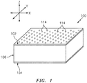
- FIG. 1 is a partial, perspective schematic illustration of an acoustic panel 100 for attenuating noise.
- This acoustic panel 100 may be configured to attenuate noise generated by an aircraft propulsion system such as, for example, a turbofan propulsion system or a turbojet propulsion system.
- the acoustic panel 100 may be configured with a nacelle of the propulsion system.
- the acoustic panel 100 may be configured as or with an inner or outer barrel, a translating sleeve of a thrust reverser, a blocker door, etc.
- the acoustic panel 100 may be configured with another component / structure of the aircraft such as its fuselage or a wing.
- the acoustic panel 100 may be configured to also or alternatively attenuate aircraft related noise other than that generated by the propulsion system.
- the acoustic panel 100 of the present disclosure may alternatively be configured for non-aircraft applications.
- the acoustic panel 100 extends longitudinally along an x-axis.
- the acoustic panel 100 extends laterally along a y-axis.
- the acoustic panel 100 extends vertically along a z-axis.
- the term "vertical" is used herein to describe a depthwise panel direction and is not limited to a gravitational up/down direction.
- the x-y plane is shown as a generally flat plane. However, in other embodiments, the x-y plane and, thus, the acoustic panel 100 may be curved and/or follow an undulating geometry.
- the x-y plane and, thus, the acoustic panel 100 may be arcuate, cylindrical or conical with or without radial undulations.
- the vertical direction may change at different locations along the x-y plane; e.g., the vertical direction may be a radial direction for a cylindrical or conical acoustic panel.
- the acoustic panel 100 includes a perforated first (e.g., face) skin 102, a solid non-perforated second (e.g., back) skin 104 and a cellular core 106.
- the cellular core 106 is disposed and extends vertically between the first skin 102 and the second skin 104.
- the cellular core 106 is also connected to the first skin 102 and the second skin 104.
- the cellular core 106 may be fused, adhered, welded, brazed and/or otherwise bonded to the first skin 102 and/or the second skin 104.
- the cellular core 106 may also or alternatively be mechanically fastened to the first skin 102 and/or the second skin 104.
- the cellular core 106 may be formed integral with the first skin 102 and/or the second skin 104 as a monolithic body using, for example, additive manufacturing. However, the present disclosure is not limited to any particular manufacturing methods.
- the first skin 102 may be configured as a relatively thin sheet or layer of material that extends longitudinally and laterally along the x-y plane.
- This first skin material may include, but is not limited to, a thermoplastic polymer, a thermoset polymer, a fiber reinforced polymer (thermoset or thermoplastic) matrix composite (e.g., fiberglass composite, carbon fiber composite, aramid fiber composite, composite reinforced by any combination of glass, carbon, aramid or other fibers, etc.), metal, alloys, metal matrix composite, ceramic, or ceramic matrix composite, or a combination thereof.
- the first skin 102 has a vertical thickness 108 that extends vertically between opposing side surfaces 110 and 112.
- the first skin 102 includes a plurality of perforations 114; e.g., apertures such as through-holes (see also FIG.1 ). Each of these perforations 114 extends generally vertically through the first skin 102 between its side surfaces 110 and 112. In other embodiments, the perforations 114 may be non-uniform through the thickness 108 and/or may be non-perpendicular to the side surfaces 110 and/or 112.
- the second skin 104 may be configured as a relatively thin sheet or layer of (e.g., continuous and uninterrupted) material that extends longitudinally and laterally along the x-y plane (see FIG. 1 ).
- This second skin material may include, but is not limited to, a thermoplastic polymer, a thermoset polymer, a fiber reinforced polymer (thermoset or thermoplastic) matrix composite (e.g., fiberglass composite, carbon fiber composite, aramid fiber composite, composite reinforced by any combination of glass, carbon, aramid or other fibers, etc.), metal, alloys, metal matrix composite, ceramic, or ceramic matrix composite, or a combination thereof.
- the second skin material may be the same as or different than the first skin material.
- the second skin 104 has a vertical thickness 116 that extends vertically between opposing side surfaces 118 and 120. This vertical thickness 116 may be substantially equal to or different (e.g., greater or less) than the vertical thickness 108 of the first skin 102. The thickness 108 of the first skin 102 and/or the thickness 116 of the second skin 104 may be uniform or non-uniform along the x-y plane.
- the cellular core 106 extends longitudinally and laterally along the x-y plane.
- the cellular core 106 has a vertical thickness 122 that extends vertically between opposing core sides, which sides are respectively abutted against the first skin 102 and the second skin 104 and their side surfaces 112 and 118.
- the vertical thickness 122 may be substantially greater than the vertical thicknesses 108 and 116 of the first skin 102 and/or the second skin 104, respectively.
- the vertical thickness 122 for example, may be at least ten to forty times (10-40x), or more, greater than the vertical thicknesses 108 and 116; however, the acoustic panel 100 of the present disclosure is not limited to such an exemplary embodiment.
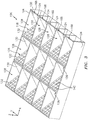
- the cellular core 106 includes a plurality of solid non-perforated walls 124 (e.g., cavity sidewalls) and one or more arrays of corrugations 126.
- the walls 124 and corrugations 126 are arranged together to configure the cellular core 106 as an open cavity (e.g., open cell) structure.
- This open cavity structure forms a plurality of cavities 128 (each including divided sub-cavities 128A and 128B) vertically between the first skin 102 and the second skin 104.
- Each of these cavities 128 may be fluidly coupled with one or more respective perforations 114 in the first skin 102 (see FIG. 2 ).
- each of the walls 124 has a length that extends longitudinally along the x-axis.
- Each of the walls 124 has a thickness that extends laterally along the y-axis.
- each of the walls 124 has a height 122 that extends vertically between the first skin 102 and the second skin 104.
- Each of the walls 124 is at least partially (or completely) connected to or otherwise engaged with the first skin 102 and/or the second skin 104.
- Each of the exemplary walls 124 of FIG. 4 is orientated substantially perpendicular to the first skin 102 and the second skin 104; e.g., at a ninety-degree angle to the skins 102 and 104.
- one or more of the walls 124 may be angularly offset from the first skin 102 and/or the second skin 104 by a non-ninety-degree angle; e.g., an acute angle or an obtuse angle.
- the walls 124 are arranged generally parallel with one another; see also FIG. 3 .
- the walls 124 are laterally spaced from one another along the y-axis so as to respectively form the cavities 128 between the walls 124.
- Each of the walls 124 shown in FIG. 4 therefore respectively forms lateral sides of adjacent cavities 128 on either side of the respective wall 124.
- Each of the walls 124 thereby also fluidly separates those cavities 128 on either side of the wall 124.
- each of the corrugations 126 in each array are disposed and extend laterally between a laterally adjacent pair of the walls 124; see also FIG. 4 .
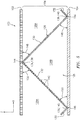
- Each of the corrugations 126 includes a solid non-perforated baffle 130 and a porous (e.g., perforated) septum 132.
- one or more or each of the corrugations 126 includes only porous (e.g. perforated) septa 132, or only solid non-perforated baffles 130 in an alternating periodic or non-periodic pattern along the y-axis or the x-axis or both.
- the baffle 130 has a width extending laterally between opposing lateral sides. These lateral sides are at least partially (or completely) connected to or otherwise engaged with a respective laterally adjacent pair of the walls 124.
- the baffle 130 has a length extending diagonally (e.g., vertically and longitudinally) between opposing top and bottom ends 134 and 136. Note, the terms "top” and “bottom” are used above to describe ends of the baffle 130 as situated in the drawings and are not intended to limit the baffle 130 or the acoustic panel 100 to such an exemplary gravitational orientation.
- the septum 132 has a width extending laterally between opposing lateral sides. These lateral sides are connected to or otherwise engaged with a respective laterally adjacent pair of the walls 124.
- the septum 132 has a length extending diagonally (e.g., vertically and longitudinally) between opposing top and bottom ends 138 and 140. Note, the terms “top” and “bottom” are used above to describe ends of the septum 132 as situated in the drawings and are not intended to limit the septum 132 or the acoustic panel 100 to such an exemplary gravitational orientation.
- the septum 132 includes one or more perforations 142.
- the perforations 142 are configured as through holes.
- the perforations 142 may be formed by interconnected pores in the septum 132 where the septum material, for example, has an open cell porous structure.
- the top end 134 of the baffle 130 is connected at least partially (or completely) to or otherwise engaged with the first skin 102. This top end 134 is also longitudinally connected to the top end 138 of the septum 132 at an interface 144 between the baffle 130 and the septum 132.
- the bottom end 136 of the baffle 130 is connected to or otherwise engaged with the second skin 104. This bottom end 136 is also longitudinally connected to the bottom end 140 of a septum 132 of an adjacent one of the corrugations 126 at an interface 146.
- the baffle 130 extends vertically between the first skin 102 and the second skin 104 and longitudinally between the septums 132.
- the baffle 130 is therefore angularly offset from the first skin 102 and the second skin 104 by an included angle 148; e.g., between 30-60 degrees.
- This angle 148 is an acute angle such as, but not limited to, about forty-five degrees (45°).
- the top end 138 of the septum 132 is at least partially (or completely) connected to or otherwise engaged with the first skin 102. This top end 138 is also longitudinally connected to the top end 134 of the baffle 130 as described above.
- the bottom end 140 of the septum 132 is at least partially (or completely) connected to or otherwise engaged with the second skin 104. This bottom end 140 is also longitudinally connected to the bottom end 136 of a baffle 130 of an adjacent one of the corrugations 126 at an interface; e.g., the interface 146.
- the septum 132 extends vertically between the first skin 102 and the second skin 104 and longitudinally between the baffles 130.
- the septum 132 is therefore angularly offset from the first skin 102 and the second skin 104 by an included angle 150; e.g., between 30-60 degrees.
- This angle 150 may be an acute angle such as, but not limited to, about forty-five degrees (45°).
- the angle 150 may be substantially equal to the angle 148 as shown in FIG. 5 .
- the angle 150 may be different from the angle 148; e.g., a larger or smaller acute angle, or a right angle.
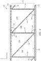
- the angle 150 may be about ninety degrees (90°) and the angle 148 may be about forty-five degrees (45°) as shown in FIG. 6 .
- the angle 148 may be about ninety degrees (90°) and the angle 150 may be about forty-five degrees (45°).
- each of the cavities 128 extends longitudinally between and is formed by a longitudinally adjacent pair of the baffles 130.
- Each septum 132 is disposed within and divides a respective one of the cavities 128 into fluidly coupled sub-cavities 128A and 128B. More particularly, the perforations 142 in the septum 132 fluidly couple the sub-cavities 128A and 128B together.
- Each of the cavities 128 forms a resonance chamber 152.
- a length 154 of the resonance chamber 152 extends diagonally (e.g., longitudinally and vertically) between the first skin 102 and the second skin 104 and through a respective one of the septums 132.
- the length 154 of the resonance chamber 152 therefore is longer than the vertical thickness 122 of the cellular core 106. This enables noise attenuation of relatively low frequency noise without increasing the vertical thickness 122 of the cellular core 106 and, thus, a vertical thickness of the acoustic panel 100.
- each resonance chamber 152 may receive noise waves through the perforations 114 in the first skin 102.
- the resonance chamber 152 may reverse the phase of one or more frequencies of those sound waves using known acoustic reflection principles and subsequently direct the reverse phase sound waves out of the acoustic panel 100 through the perforations 114 to destructively interfere with other incoming noise waves.
- the cellular core 106 may be constructed from any suitable material or materials.
- the cellular core 106 may be constructed from a thermoplastic polymer, a thermoset polymer, a fiber reinforced thermoset or thermoplastic polymer matrix composite (e.g., fiberglass composite, carbon fiber composite, aramid fiber composite, composite reinforced by any combination of glass, carbon, aramid or other fibers), metal, alloys, metal matrix composite, ceramic, or ceramic matrix composite, or a combination thereof.
- One or more of the components of the cellular core 106 may be constructed from the same or a like material.
- one or more of the components of the cellular core 106 may be constructed from a different material than one or more of the other components of the cellular core 106.
- the cellular core 106 may be constructed from the same material(s) as the first skin 102 and/or the second skin 104, or from a different material or materials.
- one or more elements 156A-F (generally referred to as "156") of the acoustic panel 100 and, more particularly, the cellular core 106 may be configured with one or more structural reinforcements 158A-F (generally referred to as "158"). These structural reinforcements 158 are provided to increase rigidity, stability, strength and/or structural integrity of the corresponding element(s) 156 as well as the acoustic panel 100 as a whole.
- Examples of the one or more elements 156 include, but are not limited to: (A) one, some or each of the baffles 130; (B) one, some or each of the septums 132; (C) one, some or each of the arrays of corrugations 126; and (D) a combination of any two or more of (A) to (C).
- the elements 156 may also or alternatively include one, some or each of the walls 124.
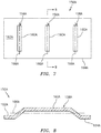
- FIGS. 7 and 8 illustrate a portion of the acoustic panel element 156A configured with an array of the structural reinforcements 158A.
- Each structural reinforcement 158A of FIGS. 7 and 8 is configured as a discrete rib 160A.
- Each rib 160A may be stamped, molded and/or otherwise formed in the acoustic panel element 156A to project out from an exterior surface 162A of the acoustic panel element 156A. More particularly, each rib 160A is formed in the acoustic panel element 156A to project out from a (e.g., planar) base 164A of the acoustic panel element 156A, which base 164A defines the exterior surface 162A.
- a (e.g., planar) base 164A of the acoustic panel element 156A which base 164A defines the exterior surface 162A.
- Each rib 160A extends along a trajectory 166A, where the trajectories 166A of the ribs 160A may be parallel with one another as shown in FIG. 7 . In other embodiments, however, the trajectories 166A of some of the ribs 160A may be non-parallel; e.g., angled to one another. Note, the term "trajectory" may describe a centerline that follows along a length of a feature, where that length is greater than other dimensions (e.g., a width and/or a thickness) of the feature. Each trajectory 166A of FIG. 7 is a straight-line trajectory. However, in other embodiments, the trajectory 166A of one or more of the ribs 160A may alternatively be a curved or otherwise convoluted line trajectory.
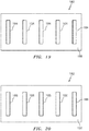
- FIGS. 9 to 11 illustrate a portion of the acoustic panel element 156B configured with an array of the structural reinforcements 158B and 158C.
- Each structural reinforcement 158B, 158C of FIGS. 9 to 11 is configured as a discrete rib 160B, 160C.
- Each rib 160B may be formed in the acoustic panel element 156B to project out from an exterior surface 162B of the acoustic panel element 156B. More particularly, each rib 160B is formed in the acoustic panel element 156B to project out from a (e.g., planar) base 164B of the acoustic panel element 156B, which base 164B defines the exterior surface 162B and an opposite exterior surface 163B.
- a (e.g., planar) base 164B of the acoustic panel element 156B which base 164B defines the exterior surface 162B and an opposite exterior surface 163B.
- Each rib 160C may be formed in the acoustic panel element 156B to project out from the exterior surface 163B. More particularly, each rib 160C is formed in the acoustic panel element 156B to project out from the base 164B such that each rib 160C is arranged on an opposing side of the base 164B from each rib 160B.
- Each rib 160B extends along a trajectory 166B, where the trajectories 166B of the ribs 160B may be parallel with one another as shown in FIG. 9 . In other embodiments, however, the trajectories 166B of some of the ribs 160B may be non-parallel; e.g., angled to one another.
- Each rib 160C extends along a trajectory 166C, where the trajectories 166C of the ribs 160C may be parallel with one another as shown in FIG. 9 . In other embodiments, however, the trajectories 166C of some of the ribs 160C may be non-parallel; e.g., angled to one another.
- the trajectories 166B of the ribs 160B may also be parallel with the trajectories 166C of the ribs 160C as shown in FIG. 9 . In other embodiments, however, the trajectories 166B and 166C of some of the ribs 160B and 160C may be non-parallel; e.g., angled to one another. Each trajectory 166B, 166C of FIG. 9 is straight-line trajectory. However, in other embodiments, the trajectory 166B, 166C of one or more of the ribs 160B, 160C may alternatively be a curved or otherwise convoluted line trajectory.
- Each structural reinforcement 158 described above includes a single discrete rib (generally referred to as "160"). However, in other embodiments, one or more of the structural reinforcements (e.g., 158C-F) may each include a plurality of interconnected ribs as shown, for example, in FIGS. 12 to 15 .
- the structural reinforcement 158C of FIG. 12 for example, includes a first rib 160D and a second rib 160E.
- the first rib 160D extends along a first trajectory 166D and the second rib 160E extends along a second trajectory 166E.
- the first trajectory 166D and the second trajectory 166E are straight-line trajectories; however, in other embodiments, one or both of these trajectories 166D and 166E may alternatively be curved or otherwise convoluted line trajectories.
- the first trajectory 166D of the first rib 160D is non-parallel with the second trajectory 166E of the second rib 160E.
- the first trajectory 166D and the first rib 160D of FIG. 12 for example, are perpendicular and coincident with the second trajectory 166E and the second rib 160E.
- an included angle between first and second trajectories 166F and 166G and ribs 160F and 160G of the structural reinforcement 158D may be acute (or obtuse) as shown in FIG. 13 for example.
- the first rib 160D intersects and thereby runs into the second rib 160E.
- the first rib 160D of FIG. 12 bisects the second rib 160E and the second rib 160E bisects the first rib 160D.
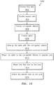
- FIG. 16 is a flow diagram of a method 1600 for forming a structured panel such as, but not limited to, the structured panel 100 embodiments described above.
- the first skin 102 is formed or otherwise provided.
- This first skin 102 may be constructed from polymer material such as, but not limited to, thermoplastic polymer material or thermoset polymer material.
- the first skin 102 may be constructed from a layup of fiber reinforcement within a polymer (e.g., thermoplastic or thermoset) matrix.
- fiber reinforcement include, but are not limited to, continuous, long discontinuous, short chopped and/or fabric (woven) or other arrangement of fibers of fiberglass, carbon fibers, aramid fibers or any combination thereof. These fibers may be arranged in one or more plies, a three-dimensional (3D) woven body, or any other arrangement.
- the first skin 102 may be formed from another non-polymeric material such as, but not limited to, sheet metal or ceramic material, or ceramic matrix composite material.
- the first skin 102 may be perforated during this step 1602 using a perforation technique such as, but not limited to, mechanical or laser drilling.
- the first skin 102 may be perforated subsequent to being attached to the core 106.
- the second skin 104 is formed or otherwise provided.
- This second skin 104 may be constructed from polymer material such as, but not limited to, thermoplastic polymer material or thermoset polymer material.
- the second skin 104 may be constructed from a layup of fiber reinforcement within a polymer (e.g., thermoplastic or thermoset) matrix.
- fiber reinforcement include, but are not limited to, continuous, long discontinuous, short chopped and/or fabric (woven) or other arrangement of fibers of fiberglass, carbon fibers, aramid fibers or any combination thereof. These fibers may be arranged in one or more plies, a three-dimensional (3D) woven body, or any other arrangement.
- the second skin 104 may be formed from another non-polymeric material such as, but not limited to, sheet metal or ceramic material, or ceramic matrix composite material.
- a plurality of corrugated ribbons 168 are formed or otherwise provided.
- Each of these corrugated ribbons 168 includes a respective one of the longitudinally extending arrays of the corrugations 126 and, thus, sets of baffles 130 and septums 132.
- Each corrugated ribbon 168 may be constructed from polymer material such as, but not limited to, thermoplastic material or thermoset material.
- each corrugated ribbon 168 may be constructed from a layup of fiber reinforcement within a polymer (e.g., thermoplastic or thermoset) matrix.
- fiber reinforcement examples include, but are not limited to, continuous, long discontinuous, short chopped and/or fabric (woven) or other arrangement of fibers of fiberglass, carbon fibers, aramid fibers or any combination thereof. These fibers may be arranged in one or more plies, a three-dimensional (3D) woven body, or any other arrangement. In other embodiments, however, each corrugated ribbon 168 may be formed from another non-polymeric material such as, but not limited to, sheet metal or ceramic material, or ceramic matrix composite material.
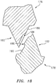
- FIG. 17 schematically illustrates an exemplary sequence of processes for forming the corrugated ribbons 168.
- a ribbon of material 170 e.g., fiber-reinforced thermoplastic or thermoset polymer or polymer matrix composite
- the ribbon of material 170 may be formed from a stock roll 172 of fiber-reinforced thermoplastic consolidate laminate, which may be processed (e.g., rolled and/or cut) to provide the ribbon with a predetermined width and thickness.
- short chopped fibers within a thermoplastic resin matrix may be extruded into the ribbon of material 170.
- the ribbon of material 170 may be formed from a stock roll 172 of fiber-reinforced thermoset polymer or polymer matrix composite fabric or matt or prepreg that is partially cured, which may be processed (e.g., rolled and/or cut) to provide the ribbon with a predetermined width and thickness.
- a stock roll 172 of fiber-reinforced thermoset polymer or polymer matrix composite fabric or matt or prepreg that is partially cured, which may be processed (e.g., rolled and/or cut) to provide the ribbon with a predetermined width and thickness.
- various other processes may also or alternatively be used to provide the ribbon of material 170.
- a plurality of perforations are formed in discrete regions of the ribbon of material 170. These perforations will become the perforations 142 in the septums 132, and the perforated regions will become the septums 132. The non-perforated regions of the ribbon of material 170 will become the baffles 130.
- the perforations may be formed in the regions of the ribbon of material 170 via punching, or using any other suitable technique. For example, the ribbon of material 170 may be pressed against a roller 174 with punches thereon, or against one or more wheels with punches thereon. Of course, in alternative embodiments, the perforations may be formed (e.g., punch, mechanical or laser drilled, etc.) after corrugated ribbon 168 and/or core 106 formation.
- a respective portion of the perforated ribbon of material 170 is corrugated to provide respective corrugations 126 and thereby form a corrugated ribbon 168.
- the perforated ribbon of material 170 may be fed between first and second rollers 176 and 178; e.g., roller dies, gears.
- Each of these rollers 176 and 178 includes a plurality of teeth 180, 182 or other radial projections arranged in a circular array thereabout. As the first teeth 180 mesh with the second teeth 182, the ribbon of material 170 is bent back and forth thereby forming the corrugations 126.
- each of the first teeth 180 may include one or more female die portions 184 and each of the second teeth 182 may include one or more male die portions 186.
- Each female die portion 184 may be configured as a shaped recess or indentation in a surface 188 of the first roller tooth 180.
- Each male die portion 186 may be configured as a corresponding shaped projection out from a surface 190 of the second roller tooth 182.
- each male die portion 186 mates with (projects into) a respective one of the female die portions 184 and thereby stamps a respective one of the structural reinforcements 158 in the corrugated ribbon 168.
- the female die portions 184 are configured with the first roller 176 and the male die portions 186 are configured with the second roller 178.
- both the first roller 176 and the second roller 178 may each include both female die portions 184 and male die portions 186.
- each first roller tooth 180 is configured with alternating female and male die portions 184 and 186 and each second roller tooth 182 is configured with alternative male and female die portions 186 and 184.
- the rollers 176 and 178 may configure the corrugated ribbon of material 170 with structural reinforcements 158 as shown, for example, in FIGS. 9-11 .
- the present disclosure is not limited to the above die portions configuration. Alternate embodiments, for example, can include any combinations of male and female die portions and die patterns on all or select first and second rollers teeth.
- the first roller 176 and/or the second roller 178 may be heated during the corrugating and the stamping.
- the ribbon may be thermoformed to the desired corrugated shape.
- thermoset polymer material or matrix is used, the ribbon may be shaped and partially cured.
- the first roller 176 and/or the second roller 178 may not (or may under certain conditions) be heated during the corrugating and the stamping, depending on targeted degree of partial or no curing of the thermoset polymer or thermoset polymer matrix material, respectively.
- each wall 124 may be constructed from polymer material such as, but not limited to, thermoplastic polymer or fiber reinforced thermoplastic polymer matrix material or thermoset polymer or fiber reinforced thermoset polymer matrix material, or metal, or ceramic or ceramic matrix composite.
- each wall 124 may be constructed from a layup of fiber reinforcement within a polymer (e.g., thermoplastic or thermoset) matrix.
- fiber reinforcement include, but are not limited to continuous, long discontinuous, short chopped and/or fabric (woven) or other arrangement of fibers of fiberglass, carbon fibers, aramid fibers or any combination thereof. These fibers may be arranged in one or more plies, a three-dimensional (3D) woven body, or any other arrangement.
- each corrugated ribbon 168 is arranged laterally between an adjacent pair of the walls 124.
- the walls 124 are attached to the corrugated ribbons 168 to form the cellular core 106.
- the walls 124 may be bonded to the corrugated ribbons 168 using, for example, ultrasonic welding, resistance welding, consolidation within an autoclave or other means (e.g., tooling with a device for exerting pressure such as a press), welding via induction heating, or adhering with an adhesive.
- other bonding techniques may also or alternatively be used to attach each wall 124 to the respective corrugated ribbon(s) 168.
- step 1614 the first skin 102 is bonded or otherwise attached to the core 106.
- step 1616 the second skin 104 is bonded or otherwise attached to the core 106.
- the steps 1614 and 1616 may be performed sequentially (e.g., either 1614 and then 1616, or 1616 and then 1614). Alternatively, the steps 1614 and 1616 may be performed substantially simultaneously.
Landscapes
- Engineering & Computer Science (AREA)
- Physics & Mathematics (AREA)
- Acoustics & Sound (AREA)
- Multimedia (AREA)
- Aviation & Aerospace Engineering (AREA)
- Mechanical Engineering (AREA)
- Chemical & Material Sciences (AREA)
- Combustion & Propulsion (AREA)
- Laminated Bodies (AREA)
Applications Claiming Priority (2)
| Application Number | Priority Date | Filing Date | Title |
|---|---|---|---|
| US201862766606P | 2018-12-14 | 2018-12-14 | |
| US16/382,450 US11398214B2 (en) | 2018-12-14 | 2019-04-12 | Forming a structured panel with one or more structural reinforcements |
Publications (2)
| Publication Number | Publication Date |
|---|---|
| EP3671727A1 true EP3671727A1 (fr) | 2020-06-24 |
| EP3671727B1 EP3671727B1 (fr) | 2024-09-04 |
Family
ID=68917369
Family Applications (1)
| Application Number | Title | Priority Date | Filing Date |
|---|---|---|---|
| EP19216189.1A Active EP3671727B1 (fr) | 2018-12-14 | 2019-12-13 | Formation d'un panneau à structure avec un ou plusieurs renforts de structure |
Country Status (3)
| Country | Link |
|---|---|
| US (1) | US11398214B2 (fr) |
| EP (1) | EP3671727B1 (fr) |
| CN (1) | CN111318856B (fr) |
Families Citing this family (7)
| Publication number | Priority date | Publication date | Assignee | Title |
|---|---|---|---|---|
| IT201900018695A1 (it) * | 2019-10-14 | 2021-04-14 | Danieli Off Mecc | Condotto di evacuazione fumi insonorizzato |
| US20240096307A1 (en) * | 2021-02-17 | 2024-03-21 | Mitsubishi Heavy Industries, Ltd. | Panel structure |
| US11976597B2 (en) * | 2021-09-13 | 2024-05-07 | Rohr, Inc. | Low-frequency acoustic center body |
| US12078125B2 (en) | 2021-09-13 | 2024-09-03 | Rohr, Inc. | Low-frequency acoustic center body |
| US20250187744A1 (en) * | 2023-12-07 | 2025-06-12 | Rohr, Inc. | Acoustic panel for an aircraft propulsion system |
| US20250214712A1 (en) * | 2023-12-27 | 2025-07-03 | Rohr, Inc. | Acoustic panel for an aircraft propulsion system |
| US20250214713A1 (en) * | 2023-12-27 | 2025-07-03 | Rohr, Inc. | Acoustic panel for an aircraft propulsion system |
Citations (4)
| Publication number | Priority date | Publication date | Assignee | Title |
|---|---|---|---|---|
| FR2201010A5 (fr) * | 1972-09-01 | 1974-04-19 | Short Brothers & Harland Ltd | |
| US5498462A (en) * | 1994-04-01 | 1996-03-12 | Hexcel Corporation | High thermal conductivity non-metallic honeycomb |
| US9704467B1 (en) * | 2016-04-15 | 2017-07-11 | Rohr, Inc. | Acoustic panel with corrugated baffles and septums |
| US20180229829A1 (en) * | 2017-02-14 | 2018-08-16 | Rohr, Inc. | Method for forming a structural panel |
Family Cites Families (72)
| Publication number | Priority date | Publication date | Assignee | Title |
|---|---|---|---|---|
| US2333343A (en) | 1937-04-22 | 1943-11-02 | Armzen Company | Method of making structural materials |
| US3011602A (en) | 1959-07-13 | 1961-12-05 | Lockheed Aircraft Corp | Panel construction |
| US3341395A (en) | 1962-12-03 | 1967-09-12 | Solar Reflection Room Corp | Lightweight structural panel |
| US3380206A (en) | 1965-09-29 | 1968-04-30 | Soundlock Corp | Lay-in acoustical ceiling panel with flexible diaphragms |
| US3439774A (en) | 1966-01-21 | 1969-04-22 | Boeing Co | Sound energy absorbing apparatus |
| US3542152A (en) | 1968-04-08 | 1970-11-24 | Gen Electric | Sound suppression panel |
| US3639106A (en) | 1968-05-06 | 1972-02-01 | Burnley Engineering Products L | Acoustic panel |
| US3507355A (en) | 1969-05-22 | 1970-04-21 | Rohr Corp | Multi-layer face material for sound absorptive duct lining material |
| US3969563A (en) | 1969-08-28 | 1976-07-13 | Hollis Sr Russell E | Protective wall structure |
| GB1274343A (en) | 1970-02-24 | 1972-05-17 | Rolls Royce | Improvements in or relating to acoustic linings |
| US3734234A (en) | 1971-11-08 | 1973-05-22 | Lockheed Aircraft Corp | Sound absorption structure |
| FR2191025B1 (fr) | 1972-07-04 | 1975-03-07 | Aerospatiale | |
| US3821999A (en) | 1972-09-05 | 1974-07-02 | Mc Donnell Douglas Corp | Acoustic liner |
| US3831710A (en) | 1973-01-24 | 1974-08-27 | Lockheed Aircraft Corp | Sound absorbing panel |
| US3850261A (en) | 1973-03-01 | 1974-11-26 | Gen Electric | Wide band width single layer sound suppressing panel |
| US3819007A (en) | 1973-04-27 | 1974-06-25 | Lockheed Aircraft Corp | Controllable laminar sound absorptive structure |
| US3910374A (en) | 1974-03-18 | 1975-10-07 | Rohr Industries Inc | Low frequency structural acoustic attenuator |
| US3948346A (en) | 1974-04-02 | 1976-04-06 | Mcdonnell Douglas Corporation | Multi-layered acoustic liner |
| US4189027A (en) | 1976-08-19 | 1980-02-19 | United Technologies Corporation | Sound suppressor liners |
| US4240519A (en) | 1979-07-02 | 1980-12-23 | United Technologies Corporation | Acoustical turbine engine tail pipe plug |
| US4859517A (en) | 1987-03-16 | 1989-08-22 | Hexcel Corporation | Formable honeycomb panel |
| US5634306A (en) | 1991-11-06 | 1997-06-03 | Riegelman; Harry M. | Composite framing member construction for windows and doors |
| US5431980A (en) | 1993-02-01 | 1995-07-11 | Mccarthy; Daniel J. | Formable cellular material with synclastic behavior |
| US5543204A (en) * | 1995-01-05 | 1996-08-06 | The United States Of America As Represented By The Secretary Of The Navy | Bi-directionally corrugated sandwich construction |
| US5923003A (en) | 1996-09-09 | 1999-07-13 | Northrop Grumman Corporation | Extended reaction acoustic liner for jet engines and the like |
| FR2781719B1 (fr) * | 1998-07-30 | 2000-09-08 | Hispano Suiza Sa | Structure de nid d'abeille, notamment pour absorption du son, et son procede de fabrication |
| US5997985A (en) | 1998-09-10 | 1999-12-07 | Northrop Grumman Corporation | Method of forming acoustic attenuation chambers using laser processing of multi-layered polymer films |
| US6725541B1 (en) | 2000-01-21 | 2004-04-27 | Rolls-Royce Plc | Flow directing element and a method of manufacturing a flow directing element |
| US6598701B1 (en) | 2000-06-30 | 2003-07-29 | 3M Innovative Properties Company | Shaped microperforated polymeric film sound absorbers and methods of manufacturing the same |
| US6949282B2 (en) | 2000-07-07 | 2005-09-27 | Delphi Technologies, Inc. | Contoured crushable composite structural members and methods for making the same |
| US7297390B2 (en) | 2002-01-28 | 2007-11-20 | Simmons Richard A | Structural polymer core assembly, method of manufacture and method of use |
| JP4231792B2 (ja) | 2002-03-26 | 2009-03-04 | 宇部日東化成株式会社 | 中空構造板、その製造方法及びその製造装置 |
| GB0223697D0 (en) | 2002-10-14 | 2002-11-20 | Rolls Royce Plc | Acoustic liner for gas turbine engineers |
| US6871725B2 (en) | 2003-02-21 | 2005-03-29 | Jeffrey Don Johnson | Honeycomb core acoustic unit with metallurgically secured deformable septum, and method of manufacture |
| CN100402179C (zh) | 2003-11-20 | 2008-07-16 | 喀山航空工业科学研究院股份公开公司 | 生产具有曲折起皱芯的夹板的方法 |
| US20130266772A1 (en) | 2004-06-15 | 2013-10-10 | John S. Fujii | Three-dimensional wood fiber structural composites |
| US7784283B2 (en) | 2006-05-03 | 2010-08-31 | Rohr, Inc. | Sound-absorbing exhaust nozzle center plug |
| RU2413654C2 (ru) | 2006-05-24 | 2011-03-10 | Эйрбас Дойчланд Гмбх | Многослойный элемент для звукопоглощающей внутренней обшивки транспортного средства, преимущественно самолета |
| US20110100747A1 (en) | 2006-05-24 | 2011-05-05 | Airbus Operations Gmbh | Sandwich element for the sound-absorbing inner cladding of means of transport, especially for the sound-absorbing inner cladding of aircraft |
| FR2912833B1 (fr) | 2007-02-20 | 2009-08-21 | Airbus France Sas | Panneau pour le traitement acoustique |
| FR2915522A1 (fr) | 2007-04-30 | 2008-10-31 | Airbus France Sas | Panneau acoustique a caracteristique acoustique variable |
| FR2922152B1 (fr) | 2007-10-16 | 2009-11-20 | Aircelle Sa | Structure a ame alveolaire pour panneau acoustique |
| FR2925463B1 (fr) | 2007-12-21 | 2010-04-23 | Airbus France | Structure pour le traitement acoustique plus particulierement adaptee a une entree d'air d'une nacelle d'aeronef |
| FR2930764B1 (fr) | 2008-04-30 | 2010-05-07 | Airbus France | Panneau d'attenuation d'ondes intercale entre une motorisation et une entree d'air d'une nacelle d'aeronef |
| US7959109B2 (en) | 2008-07-02 | 2011-06-14 | The Boeing Company | Dual valve apparatus for aircraft engine ice protection and related methods |
| DE102008051241B4 (de) | 2008-10-10 | 2011-06-16 | Airbus Operations Gmbh | Schalldämpfer für ein Hilfstriebwerk eines Flugzeugs |
| US8025122B2 (en) | 2008-11-06 | 2011-09-27 | The Boeing Company | Acoustically treated exhaust centerbody for jet engines and associated methods |
| GB0820597D0 (en) | 2008-11-11 | 2008-12-17 | Rolls Royce Plc | A noise reduction device |
| CN101649818B (zh) | 2009-09-17 | 2011-07-20 | 秦皇岛耀华玻璃钢股份公司 | 隔音降噪型风力发电机机舱罩 |
| FR2953058B1 (fr) | 2009-11-23 | 2017-11-03 | Aircelle Sa | Peau acoustique pour un panneau acoustique d'une nacelle d'aeronef |
| FR2960334B1 (fr) * | 2010-05-19 | 2012-08-03 | Snecma | Panneau de traitement acoustique multicouches |
| DE102011008921A1 (de) | 2011-01-19 | 2012-07-19 | Rolls-Royce Deutschland Ltd & Co Kg | Gasturbinenabgaskonus |
| EP2700068A4 (fr) | 2011-04-20 | 2016-01-13 | Dresser Rand Co | Groupement de résonateurs à multiples degrés de liberté |
| EP2530010B1 (fr) | 2011-06-02 | 2013-09-18 | Bell Helicopter Textron Inc. | Panneau intégralement raidi |
| RU2014102784A (ru) * | 2011-06-29 | 2015-08-10 | Зефирос, Инк. | Звукопоглощающая панель и способ ее сборки |
| FR2979385A1 (fr) | 2011-08-22 | 2013-03-01 | Snecma | Panneau d'isolation acoustique pour turbomachine et turbomachine comportant un tel panneau |
| FR2983835B1 (fr) | 2011-12-13 | 2014-02-21 | Airbus Operations Sas | Procede de realisation d'un panneau pour le traitement acoustique |
| US9403340B2 (en) * | 2012-10-25 | 2016-08-02 | Hamilton Sundstrand Corporation | Method of manufacturing a composite load-bearing structure |
| US20140349082A1 (en) | 2013-05-21 | 2014-11-27 | The Boeing Company | Folded Core Panel |
| US8820477B1 (en) | 2013-07-29 | 2014-09-02 | The Boeing Company | Acoustic panel |
| US10184398B2 (en) | 2013-10-17 | 2019-01-22 | Rohr, Inc. | Acoustic structural panel with slanted core |
| US9284726B2 (en) | 2014-04-04 | 2016-03-15 | The Boeing Company | Pyramid waffle core structure and method of fabrication |
| US9592918B2 (en) | 2014-06-23 | 2017-03-14 | Rohr, Inc. | Acoustic liner |
| SG10201405027SA (en) * | 2014-08-19 | 2016-01-28 | Perfect Sourcing Company Ltd | Composite Panel For Green Building System |
| US9650963B2 (en) | 2015-01-29 | 2017-05-16 | Rohr, Inc. | Acoustic structural panel with herringbone core |
| CN104723616B (zh) | 2015-03-17 | 2016-07-06 | 西安交通大学 | 一种轻质正交波纹夹芯复合结构及其制备方法 |
| US9764818B2 (en) | 2016-02-10 | 2017-09-19 | Rohr, Inc. | Structural, cellular core with corrugated support walls |
| US9761216B2 (en) | 2016-02-10 | 2017-09-12 | Rohr, Inc. | Acoustic panel with angled corrugated core structures |
| US9978354B2 (en) | 2016-04-15 | 2018-05-22 | Rohr, Inc. | Acoustic panel with vertical stiffeners |
| US9620102B1 (en) * | 2016-05-02 | 2017-04-11 | Hexcel Corporation | Stepped acoustic structures with multiple degrees of freedom |
| US10309305B2 (en) | 2016-11-18 | 2019-06-04 | Rohr, Inc. | Acoustic panel with sidewall stringers |
| US10316755B2 (en) * | 2016-11-18 | 2019-06-11 | Rohr, Inc. | Acoustic panel with sidewall stringers |
-
2019
- 2019-04-12 US US16/382,450 patent/US11398214B2/en active Active
- 2019-12-13 CN CN201911285611.4A patent/CN111318856B/zh active Active
- 2019-12-13 EP EP19216189.1A patent/EP3671727B1/fr active Active
Patent Citations (4)
| Publication number | Priority date | Publication date | Assignee | Title |
|---|---|---|---|---|
| FR2201010A5 (fr) * | 1972-09-01 | 1974-04-19 | Short Brothers & Harland Ltd | |
| US5498462A (en) * | 1994-04-01 | 1996-03-12 | Hexcel Corporation | High thermal conductivity non-metallic honeycomb |
| US9704467B1 (en) * | 2016-04-15 | 2017-07-11 | Rohr, Inc. | Acoustic panel with corrugated baffles and septums |
| US20180229829A1 (en) * | 2017-02-14 | 2018-08-16 | Rohr, Inc. | Method for forming a structural panel |
Also Published As
| Publication number | Publication date |
|---|---|
| US20200193953A1 (en) | 2020-06-18 |
| US11398214B2 (en) | 2022-07-26 |
| CN111318856A (zh) | 2020-06-23 |
| CN111318856B (zh) | 2024-11-19 |
| EP3671727B1 (fr) | 2024-09-04 |
Similar Documents
| Publication | Publication Date | Title |
|---|---|---|
| EP3671727B1 (fr) | Formation d'un panneau à structure avec un ou plusieurs renforts de structure | |
| EP3364407B1 (fr) | Procédé pour former un panneau structurel | |
| EP3447760B1 (fr) | Procédé pour former un panneau structural | |
| EP3671728B1 (fr) | Panneau de structure comportant une ou plusieurs structures à panneaux multiples | |
| EP3324400B1 (fr) | Panneau acoustique avec longerons de paroi latérale | |
| EP3232435B1 (fr) | Panneau acoustique ayant des réflecteurs et des cloisons ondulés | |
| EP3205574B1 (fr) | Noyau cellulaire structural ayant des parois de support ondulées | |
| EP3206203B1 (fr) | Panneau acoustique ayant des structures de noyau ondulées inclinées | |
| EP3324401B1 (fr) | Panneau acoustique avec longerons de paroi latérale | |
| EP3748627B1 (fr) | Panneau acoustique doté d'un ou de plusieurs raidisseurs structurels | |
| EP3422342B1 (fr) | Panneau acoustique avec chambre de pliage | |
| US11359577B2 (en) | Multi-degree of freedom acoustic panel | |
| US11828229B2 (en) | Continuous slanted cell septum | |
| EP3772557A1 (fr) | Panneau structuré doté de parois de cavité non parallèles | |
| EP3553771B1 (fr) | Panneau structuré avec renfort(s) structural(aux) |
Legal Events
| Date | Code | Title | Description |
|---|---|---|---|
| PUAI | Public reference made under article 153(3) epc to a published international application that has entered the european phase |
Free format text: ORIGINAL CODE: 0009012 |
|
| STAA | Information on the status of an ep patent application or granted ep patent |
Free format text: STATUS: THE APPLICATION HAS BEEN PUBLISHED |
|
| AK | Designated contracting states |
Kind code of ref document: A1 Designated state(s): AL AT BE BG CH CY CZ DE DK EE ES FI FR GB GR HR HU IE IS IT LI LT LU LV MC MK MT NL NO PL PT RO RS SE SI SK SM TR |
|
| AX | Request for extension of the european patent |
Extension state: BA ME |
|
| STAA | Information on the status of an ep patent application or granted ep patent |
Free format text: STATUS: REQUEST FOR EXAMINATION WAS MADE |
|
| 17P | Request for examination filed |
Effective date: 20201222 |
|
| RBV | Designated contracting states (corrected) |
Designated state(s): AL AT BE BG CH CY CZ DE DK EE ES FI FR GB GR HR HU IE IS IT LI LT LU LV MC MK MT NL NO PL PT RO RS SE SI SK SM TR |
|
| STAA | Information on the status of an ep patent application or granted ep patent |
Free format text: STATUS: EXAMINATION IS IN PROGRESS |
|
| 17Q | First examination report despatched |
Effective date: 20220622 |
|
| GRAP | Despatch of communication of intention to grant a patent |
Free format text: ORIGINAL CODE: EPIDOSNIGR1 |
|
| STAA | Information on the status of an ep patent application or granted ep patent |
Free format text: STATUS: GRANT OF PATENT IS INTENDED |
|
| INTG | Intention to grant announced |
Effective date: 20240327 |
|
| GRAS | Grant fee paid |
Free format text: ORIGINAL CODE: EPIDOSNIGR3 |
|
| GRAA | (expected) grant |
Free format text: ORIGINAL CODE: 0009210 |
|
| STAA | Information on the status of an ep patent application or granted ep patent |
Free format text: STATUS: THE PATENT HAS BEEN GRANTED |
|
| AK | Designated contracting states |
Kind code of ref document: B1 Designated state(s): AL AT BE BG CH CY CZ DE DK EE ES FI FR GB GR HR HU IE IS IT LI LT LU LV MC MK MT NL NO PL PT RO RS SE SI SK SM TR |
|
| REG | Reference to a national code |
Ref country code: GB Ref legal event code: FG4D |
|
| REG | Reference to a national code |
Ref country code: CH Ref legal event code: EP |
|
| REG | Reference to a national code |
Ref country code: IE Ref legal event code: FG4D |
|
| REG | Reference to a national code |
Ref country code: DE Ref legal event code: R096 Ref document number: 602019058233 Country of ref document: DE |
|
| REG | Reference to a national code |
Ref country code: LT Ref legal event code: MG9D |
|
| REG | Reference to a national code |
Ref country code: NL Ref legal event code: MP Effective date: 20240904 |
|
| PG25 | Lapsed in a contracting state [announced via postgrant information from national office to epo] |
Ref country code: NO Free format text: LAPSE BECAUSE OF FAILURE TO SUBMIT A TRANSLATION OF THE DESCRIPTION OR TO PAY THE FEE WITHIN THE PRESCRIBED TIME-LIMIT Effective date: 20241204 |
|
| PG25 | Lapsed in a contracting state [announced via postgrant information from national office to epo] |
Ref country code: GR Free format text: LAPSE BECAUSE OF FAILURE TO SUBMIT A TRANSLATION OF THE DESCRIPTION OR TO PAY THE FEE WITHIN THE PRESCRIBED TIME-LIMIT Effective date: 20241205 Ref country code: FI Free format text: LAPSE BECAUSE OF FAILURE TO SUBMIT A TRANSLATION OF THE DESCRIPTION OR TO PAY THE FEE WITHIN THE PRESCRIBED TIME-LIMIT Effective date: 20240904 Ref country code: PL Free format text: LAPSE BECAUSE OF FAILURE TO SUBMIT A TRANSLATION OF THE DESCRIPTION OR TO PAY THE FEE WITHIN THE PRESCRIBED TIME-LIMIT Effective date: 20240904 |
|
| PG25 | Lapsed in a contracting state [announced via postgrant information from national office to epo] |
Ref country code: BG Free format text: LAPSE BECAUSE OF FAILURE TO SUBMIT A TRANSLATION OF THE DESCRIPTION OR TO PAY THE FEE WITHIN THE PRESCRIBED TIME-LIMIT Effective date: 20240904 |
|
| PG25 | Lapsed in a contracting state [announced via postgrant information from national office to epo] |
Ref country code: LV Free format text: LAPSE BECAUSE OF FAILURE TO SUBMIT A TRANSLATION OF THE DESCRIPTION OR TO PAY THE FEE WITHIN THE PRESCRIBED TIME-LIMIT Effective date: 20240904 |
|
| PG25 | Lapsed in a contracting state [announced via postgrant information from national office to epo] |
Ref country code: HR Free format text: LAPSE BECAUSE OF FAILURE TO SUBMIT A TRANSLATION OF THE DESCRIPTION OR TO PAY THE FEE WITHIN THE PRESCRIBED TIME-LIMIT Effective date: 20240904 |
|
| PG25 | Lapsed in a contracting state [announced via postgrant information from national office to epo] |
Ref country code: ES Free format text: LAPSE BECAUSE OF FAILURE TO SUBMIT A TRANSLATION OF THE DESCRIPTION OR TO PAY THE FEE WITHIN THE PRESCRIBED TIME-LIMIT Effective date: 20240904 Ref country code: RS Free format text: LAPSE BECAUSE OF FAILURE TO SUBMIT A TRANSLATION OF THE DESCRIPTION OR TO PAY THE FEE WITHIN THE PRESCRIBED TIME-LIMIT Effective date: 20241204 |
|
| PG25 | Lapsed in a contracting state [announced via postgrant information from national office to epo] |
Ref country code: RS Free format text: LAPSE BECAUSE OF FAILURE TO SUBMIT A TRANSLATION OF THE DESCRIPTION OR TO PAY THE FEE WITHIN THE PRESCRIBED TIME-LIMIT Effective date: 20241204 Ref country code: PL Free format text: LAPSE BECAUSE OF FAILURE TO SUBMIT A TRANSLATION OF THE DESCRIPTION OR TO PAY THE FEE WITHIN THE PRESCRIBED TIME-LIMIT Effective date: 20240904 Ref country code: NO Free format text: LAPSE BECAUSE OF FAILURE TO SUBMIT A TRANSLATION OF THE DESCRIPTION OR TO PAY THE FEE WITHIN THE PRESCRIBED TIME-LIMIT Effective date: 20241204 Ref country code: LV Free format text: LAPSE BECAUSE OF FAILURE TO SUBMIT A TRANSLATION OF THE DESCRIPTION OR TO PAY THE FEE WITHIN THE PRESCRIBED TIME-LIMIT Effective date: 20240904 Ref country code: HR Free format text: LAPSE BECAUSE OF FAILURE TO SUBMIT A TRANSLATION OF THE DESCRIPTION OR TO PAY THE FEE WITHIN THE PRESCRIBED TIME-LIMIT Effective date: 20240904 Ref country code: GR Free format text: LAPSE BECAUSE OF FAILURE TO SUBMIT A TRANSLATION OF THE DESCRIPTION OR TO PAY THE FEE WITHIN THE PRESCRIBED TIME-LIMIT Effective date: 20241205 Ref country code: FI Free format text: LAPSE BECAUSE OF FAILURE TO SUBMIT A TRANSLATION OF THE DESCRIPTION OR TO PAY THE FEE WITHIN THE PRESCRIBED TIME-LIMIT Effective date: 20240904 Ref country code: ES Free format text: LAPSE BECAUSE OF FAILURE TO SUBMIT A TRANSLATION OF THE DESCRIPTION OR TO PAY THE FEE WITHIN THE PRESCRIBED TIME-LIMIT Effective date: 20240904 Ref country code: BG Free format text: LAPSE BECAUSE OF FAILURE TO SUBMIT A TRANSLATION OF THE DESCRIPTION OR TO PAY THE FEE WITHIN THE PRESCRIBED TIME-LIMIT Effective date: 20240904 |
|
| REG | Reference to a national code |
Ref country code: AT Ref legal event code: MK05 Ref document number: 1721273 Country of ref document: AT Kind code of ref document: T Effective date: 20240904 |
|
| PG25 | Lapsed in a contracting state [announced via postgrant information from national office to epo] |
Ref country code: NL Free format text: LAPSE BECAUSE OF FAILURE TO SUBMIT A TRANSLATION OF THE DESCRIPTION OR TO PAY THE FEE WITHIN THE PRESCRIBED TIME-LIMIT Effective date: 20240904 |
|
| PG25 | Lapsed in a contracting state [announced via postgrant information from national office to epo] |
Ref country code: IS Free format text: LAPSE BECAUSE OF FAILURE TO SUBMIT A TRANSLATION OF THE DESCRIPTION OR TO PAY THE FEE WITHIN THE PRESCRIBED TIME-LIMIT Effective date: 20250104 Ref country code: PT Free format text: LAPSE BECAUSE OF FAILURE TO SUBMIT A TRANSLATION OF THE DESCRIPTION OR TO PAY THE FEE WITHIN THE PRESCRIBED TIME-LIMIT Effective date: 20250106 |
|
| PG25 | Lapsed in a contracting state [announced via postgrant information from national office to epo] |
Ref country code: RO Free format text: LAPSE BECAUSE OF FAILURE TO SUBMIT A TRANSLATION OF THE DESCRIPTION OR TO PAY THE FEE WITHIN THE PRESCRIBED TIME-LIMIT Effective date: 20240904 Ref country code: SM Free format text: LAPSE BECAUSE OF FAILURE TO SUBMIT A TRANSLATION OF THE DESCRIPTION OR TO PAY THE FEE WITHIN THE PRESCRIBED TIME-LIMIT Effective date: 20240904 |
|
| PG25 | Lapsed in a contracting state [announced via postgrant information from national office to epo] |
Ref country code: AT Free format text: LAPSE BECAUSE OF FAILURE TO SUBMIT A TRANSLATION OF THE DESCRIPTION OR TO PAY THE FEE WITHIN THE PRESCRIBED TIME-LIMIT Effective date: 20240904 Ref country code: EE Free format text: LAPSE BECAUSE OF FAILURE TO SUBMIT A TRANSLATION OF THE DESCRIPTION OR TO PAY THE FEE WITHIN THE PRESCRIBED TIME-LIMIT Effective date: 20240904 |
|
| PG25 | Lapsed in a contracting state [announced via postgrant information from national office to epo] |
Ref country code: CZ Free format text: LAPSE BECAUSE OF FAILURE TO SUBMIT A TRANSLATION OF THE DESCRIPTION OR TO PAY THE FEE WITHIN THE PRESCRIBED TIME-LIMIT Effective date: 20240904 |
|
| PG25 | Lapsed in a contracting state [announced via postgrant information from national office to epo] |
Ref country code: IT Free format text: LAPSE BECAUSE OF FAILURE TO SUBMIT A TRANSLATION OF THE DESCRIPTION OR TO PAY THE FEE WITHIN THE PRESCRIBED TIME-LIMIT Effective date: 20240904 Ref country code: SK Free format text: LAPSE BECAUSE OF FAILURE TO SUBMIT A TRANSLATION OF THE DESCRIPTION OR TO PAY THE FEE WITHIN THE PRESCRIBED TIME-LIMIT Effective date: 20240904 |
|
| REG | Reference to a national code |
Ref country code: DE Ref legal event code: R097 Ref document number: 602019058233 Country of ref document: DE |
|
| PG25 | Lapsed in a contracting state [announced via postgrant information from national office to epo] |
Ref country code: MC Free format text: LAPSE BECAUSE OF FAILURE TO SUBMIT A TRANSLATION OF THE DESCRIPTION OR TO PAY THE FEE WITHIN THE PRESCRIBED TIME-LIMIT Effective date: 20240904 |
|
| PG25 | Lapsed in a contracting state [announced via postgrant information from national office to epo] |
Ref country code: DK Free format text: LAPSE BECAUSE OF FAILURE TO SUBMIT A TRANSLATION OF THE DESCRIPTION OR TO PAY THE FEE WITHIN THE PRESCRIBED TIME-LIMIT Effective date: 20240904 |
|
| PLBE | No opposition filed within time limit |
Free format text: ORIGINAL CODE: 0009261 |
|
| STAA | Information on the status of an ep patent application or granted ep patent |
Free format text: STATUS: NO OPPOSITION FILED WITHIN TIME LIMIT |
|
| REG | Reference to a national code |
Ref country code: CH Ref legal event code: PL |
|
| 26N | No opposition filed |
Effective date: 20250605 |
|
| PG25 | Lapsed in a contracting state [announced via postgrant information from national office to epo] |
Ref country code: LU Free format text: LAPSE BECAUSE OF NON-PAYMENT OF DUE FEES Effective date: 20241213 |
|
| PG25 | Lapsed in a contracting state [announced via postgrant information from national office to epo] |
Ref country code: SE Free format text: LAPSE BECAUSE OF FAILURE TO SUBMIT A TRANSLATION OF THE DESCRIPTION OR TO PAY THE FEE WITHIN THE PRESCRIBED TIME-LIMIT Effective date: 20240904 |
|
| REG | Reference to a national code |
Ref country code: BE Ref legal event code: MM Effective date: 20241231 |
|
| PG25 | Lapsed in a contracting state [announced via postgrant information from national office to epo] |
Ref country code: BE Free format text: LAPSE BECAUSE OF NON-PAYMENT OF DUE FEES Effective date: 20241231 |
|
| PG25 | Lapsed in a contracting state [announced via postgrant information from national office to epo] |
Ref country code: CH Free format text: LAPSE BECAUSE OF NON-PAYMENT OF DUE FEES Effective date: 20241231 |
|
| PG25 | Lapsed in a contracting state [announced via postgrant information from national office to epo] |
Ref country code: IE Free format text: LAPSE BECAUSE OF NON-PAYMENT OF DUE FEES Effective date: 20241213 |
|
| PGFP | Annual fee paid to national office [announced via postgrant information from national office to epo] |
Ref country code: DE Payment date: 20251126 Year of fee payment: 7 |
|
| PGFP | Annual fee paid to national office [announced via postgrant information from national office to epo] |
Ref country code: GB Payment date: 20251120 Year of fee payment: 7 |
|
| PGFP | Annual fee paid to national office [announced via postgrant information from national office to epo] |
Ref country code: FR Payment date: 20251120 Year of fee payment: 7 |