EP3671761A1 - Évaluation de la performance fonctionnelle d'un individu - Google Patents
Évaluation de la performance fonctionnelle d'un individu Download PDFInfo
- Publication number
- EP3671761A1 EP3671761A1 EP18382973.8A EP18382973A EP3671761A1 EP 3671761 A1 EP3671761 A1 EP 3671761A1 EP 18382973 A EP18382973 A EP 18382973A EP 3671761 A1 EP3671761 A1 EP 3671761A1
- Authority
- EP
- European Patent Office
- Prior art keywords
- max
- vector
- tensor
- signal
- monitoring system
- Prior art date
- Legal status (The legal status is an assumption and is not a legal conclusion. Google has not performed a legal analysis and makes no representation as to the accuracy of the status listed.)
- Pending
Links
Images


Classifications
-
- G—PHYSICS
- G16—INFORMATION AND COMMUNICATION TECHNOLOGY [ICT] SPECIALLY ADAPTED FOR SPECIFIC APPLICATION FIELDS
- G16H—HEALTHCARE INFORMATICS, i.e. INFORMATION AND COMMUNICATION TECHNOLOGY [ICT] SPECIALLY ADAPTED FOR THE HANDLING OR PROCESSING OF MEDICAL OR HEALTHCARE DATA
- G16H50/00—ICT specially adapted for medical diagnosis, medical simulation or medical data mining; ICT specially adapted for detecting, monitoring or modelling epidemics or pandemics
- G16H50/20—ICT specially adapted for medical diagnosis, medical simulation or medical data mining; ICT specially adapted for detecting, monitoring or modelling epidemics or pandemics for computer-aided diagnosis, e.g. based on medical expert systems
-
- G—PHYSICS
- G16—INFORMATION AND COMMUNICATION TECHNOLOGY [ICT] SPECIALLY ADAPTED FOR SPECIFIC APPLICATION FIELDS
- G16H—HEALTHCARE INFORMATICS, i.e. INFORMATION AND COMMUNICATION TECHNOLOGY [ICT] SPECIALLY ADAPTED FOR THE HANDLING OR PROCESSING OF MEDICAL OR HEALTHCARE DATA
- G16H50/00—ICT specially adapted for medical diagnosis, medical simulation or medical data mining; ICT specially adapted for detecting, monitoring or modelling epidemics or pandemics
- G16H50/30—ICT specially adapted for medical diagnosis, medical simulation or medical data mining; ICT specially adapted for detecting, monitoring or modelling epidemics or pandemics for calculating health indices; for individual health risk assessment
-
- A—HUMAN NECESSITIES
- A61—MEDICAL OR VETERINARY SCIENCE; HYGIENE
- A61B—DIAGNOSIS; SURGERY; IDENTIFICATION
- A61B5/00—Measuring for diagnostic purposes; Identification of persons
- A61B5/103—Measuring devices for testing the shape, pattern, colour, size or movement of the body or parts thereof, for diagnostic purposes
- A61B5/11—Measuring movement of the entire body or parts thereof, e.g. head or hand tremor or mobility of a limb
- A61B5/1113—Local tracking of patients, e.g. in a hospital or private home
- A61B5/1114—Tracking parts of the body
-
- A—HUMAN NECESSITIES
- A61—MEDICAL OR VETERINARY SCIENCE; HYGIENE
- A61B—DIAGNOSIS; SURGERY; IDENTIFICATION
- A61B5/00—Measuring for diagnostic purposes; Identification of persons
- A61B5/103—Measuring devices for testing the shape, pattern, colour, size or movement of the body or parts thereof, for diagnostic purposes
- A61B5/11—Measuring movement of the entire body or parts thereof, e.g. head or hand tremor or mobility of a limb
- A61B5/1118—Determining activity level
-
- A—HUMAN NECESSITIES
- A61—MEDICAL OR VETERINARY SCIENCE; HYGIENE
- A61B—DIAGNOSIS; SURGERY; IDENTIFICATION
- A61B2562/00—Details of sensors; Constructional details of sensor housings or probes; Accessories for sensors
- A61B2562/02—Details of sensors specially adapted for in-vivo measurements
- A61B2562/0219—Inertial sensors, e.g. accelerometers, gyroscopes, tilt switches
-
- A—HUMAN NECESSITIES
- A61—MEDICAL OR VETERINARY SCIENCE; HYGIENE
- A61B—DIAGNOSIS; SURGERY; IDENTIFICATION
- A61B2562/00—Details of sensors; Constructional details of sensor housings or probes; Accessories for sensors
- A61B2562/04—Arrangements of multiple sensors of the same type
- A61B2562/046—Arrangements of multiple sensors of the same type in a matrix array
-
- A—HUMAN NECESSITIES
- A61—MEDICAL OR VETERINARY SCIENCE; HYGIENE
- A61B—DIAGNOSIS; SURGERY; IDENTIFICATION
- A61B5/00—Measuring for diagnostic purposes; Identification of persons
- A61B5/72—Signal processing specially adapted for physiological signals or for diagnostic purposes
- A61B5/7235—Details of waveform analysis
- A61B5/7253—Details of waveform analysis characterised by using transforms
- A61B5/7257—Details of waveform analysis characterised by using transforms using Fourier transforms
Definitions
- the present disclosure relates to systems for assessing the functional performance of an individual such as systems for identifying the state of fragile or robust of the individual or systems for identifying individuals with high risk of fractures and other health related adverse outcomes.
- Frailty is a clinical syndrome characterised by increased vulnerability to low intensity stressors. Frail elderly individuals have a reduced functional performance capacity. They are independent in their basic daily life activities but have a greater risk of becoming dependent as a consequence of a minor event, such as a respiratory or urinary tract infection, for example. The pathophysiological origin of this syndrome resides in the alteration of numerous interrelated systems (immune, endocrine, musculoskeletal, and neurological systems, and so forth) which lead to a decreased homeostatic reserve and decreased adaptive capacity for the individual, which predisposes them to adverse health events. Frailty has been shown to be an independent risk factor for serious adverse health effects, such as institutionalisation, hospitalisation, falls, disability and dependency. Frail individuals have a six times greater risk of becoming dependent than healthy individuals of their same age and sex. Its prevalence varies according to the measurement instrument used and the scope of the study, but it oscillates between 15 and 25% of the population over 70 years old.
- GS Gait speed
- TAG Timed Up and Go
- SPPB Short Physical Performance Battery
- Gait speed test measures the time an individual needs to walk a predefined distance. Different versions exist based on distances of 4, 6, 8 and 10 m.
- the TUG test involves measuring the time it takes for the elderly individual to get up from a chair, walk 3 metres, turn around, return to the chair and sit down again. The outcome is considered normal if the individual performs this activity in 12 seconds or less, even though other cut points have been proposed for various purposes.
- the SPPB assesses a battery of functional tests including walking speed, the ability to get up from a chair repeatedly and balance.
- a system for assessing the functional performance of an individual may comprise:
- the provision of the sensor device and the disclosed monitoring system allows assessing the functional performance of an individual based on the study of the individual dynamics of sitting, that is, only analysing the process of sitting down and standing up performed by the individual is enough for assessing his/her functional performance.
- the stability, the force (pressure) and the kinematics used by an individual are different according to their functional performance.
- the system of the invention is capable of registering, in real time, said dynamics by the sensor device and process it by the monitoring system and assessing the functional performance of the individual. Consequently, complex exercises are no longer required and variability in the result is avoided.
- the sensor device may comprise an array of sensors. More specifically, the sensor device may be based on distributed pressure sensors, such as flexible pressure sensors, for example, large surface distributed pressure sensors.
- the sensor device may comprise an array of sensors of N r ⁇ N c that produces a N r ⁇ N c measurement matrix for each sampling time.
- the received signals may be in the form of a tri-dimensional tensor T S of order N r ⁇ N c ⁇ N S , where N r is the number of rows of the array of sensors, N c is the number of columns of the array of sensors, and N S is the number of sampling times.
- pre-processing, by the monitoring system, the signals received from the sensor device may comprise:
- Step of pre-processing allows adapting the signals coming from the sensor device and preparing them to be processed by the downstream modules (i.e. to be digested by the rest of modules of the monitoring system).
- producing, by the monitoring system, an equi-order tensor T MAX of dimensions N r ⁇ N c ⁇ N MAX may comprise:
- pre-processing, by the monitoring system, the signals received from the sensor device may comprises correcting the background of the vector V for obtaining a background corrected vector V b .
- correcting, by the monitoring system, the background of the vector V may comprise subtracting from each element of vector V the value of the minimum element of V, V MIN , such that a background corrected vector V b is obtained.
- extracting, by the monitoring system, the main features of the pre-processed signals to be used as predictor variables, predictor variables being signal descriptive variables in the time domain may comprises obtaining the signal descriptive variables in the time domain vector V DESCRIPTIVE .
- Step of extracting the main features of the pre-processed signals allows summarizing the vector V b signal in a compact way to be more easily processed by the downstream modules.
- the vector V b has a variable length and its signal behaves in a noise complicated way. These two features make this vector difficult for manipulation by the downstream modules.
- the transformation of this vector to a collection of descriptive variables with fixed dimensions and robust to the noise solves the aforementioned drawbacks.
- signal descriptive variables in the time domain may be selected from at least one of the following:
- extracting, by the monitoring system, the main features of the pre-processed signals to be used as predictor variables, predictor variables being signal time series variables in the time domain may comprise:
- reducing, by the monitoring system, the sample length of the filtered vector V b by decimation factor of d may comprise at least of the following:
- extracting, by the monitoring system, the main features of the pre-processed signals to be used as predictor variables, predictor variables being signal spectral variables in the frequency domain may comprise:
- extracting, by the monitoring system, the main features of the pre-processed signals to be used as predictor variables may comprise:
- the monitoring system may be configured to:
- Step of detecting whether any of the received signals coming from the sensor device is wrong allows detecting whether the sensor device is producing wrong measurements. These wrong measurements may be due to wrong manipulations by the individual using the sensor device or by hardware failures. Consequently, this action is convenient for troubleshooting. If the individual using the sensor device proceeds correctly following the instructions and there are no hardware problems, warning signals will not be generated. However, in the event of any manipulation error or hardware damage, a warning signal that will help avoid downstream problems will be generated.
- detecting, by the monitoring system, whether any of the received signals coming from each sensor of the array of sensors is wrong may comprise:
- detecting, by the monitoring system, whether any of the received signals coming from each sensor of the array of sensors is wrong may comprise, if a received signal is rejected, generating a warning about the rejection of the signal.
- a warning may be generated, for example, by at least one of the following actuator elements:
- assessing, by the monitoring system, the functional performance of an individual based on the extracted predictor variables may comprise:
- Step of predicting the value of TUG test uses as independent variables the obtained predictor variables.
- predicting, by the monitoring system, the value of the TUG (Timed Up Go) test of the individual based on the extracted predictor variables may comprise:
- the regression method may be selected from at least one of the following:
- assessing, by the monitoring system, the functional performance of an individual based on the extracted predictor variables may comprise:
- identifying, by the monitoring system, the state of fragile or robust of the individual based on the extracted predictor variables may comprise:
- the transfer function to calculate the output of each neuron of each layer may be selected from at least one of the following:
- the learning method may be selected from at least one of the following:
- assessing, by the monitoring system, the functional performance of an individual based on the extracted predictor variables may comprise:
- identifying, by the monitoring system, individuals with high risk of fractures and other health related adverse outcomes based on the extracted predictor variables may comprise:
- a non-transitory computer program product that causes a monitoring system to perform the steps executed by the monitoring system as described above.
- the computer program product may comprise program instructions that may be embodied on a storage medium (for example, a CD-ROM, a DVD, a USB drive, on a computer memory or on a read-only memory) or carried on a carrier signal (for example, on an electrical or optical carrier signal).
- a computer-readable medium having thereon computer-executable instructions, the computer-executable instructions upon execution configuring a monitoring system to perform the steps executed by the monitoring system as described above.
- a system 10 assessing the functional performance of an individual may comprise:
- Said assessing system 10 may be understood as an interface between the sensor device 11 and, for example, a Graphical User Interfaces application (GUIs) (not shown) configured to show, for example, the results.
- GUIs Graphical User Interfaces application
- the sensor device 11 may be based on distributed pressure sensors, such as flexible pressure sensors. More specifically, distributed pressure sensors may be useful to determine strength or pressure upon soft objects, e.g., to measure the interface pressures of a person sitting on a chair. For this application it may be necessary for the sensor device 12 to be flexible in order to adjust, for example, to the shape of a seat or floor curvature and to adequately measure the forces exerted. Moreover, the sensor must be thin enough as to not introduce reading errors. This type of sensor usually has a thickness comprised between 0.1 and a few millimetres. In order to measure pressure at different points on a surface, it is necessary that the sensor area of each element in the distributed sensor is as small as possible.
- output signals into two (on-off) or more output sensors (analogue or digital sensors).
- Flexible pressure sensors are usually made up of a series of rows and columns in matrix-type arrangements.
- the different sensor elements are calibrated by adjusting the corresponding gains and offsets or by establishing calibration curves. Data treated in this way allows generating two- and three-dimensional pressure maps in real time.
- piezoelectric technology cannot be used for static measurements due to current loss in these sensors, which makes the response signal tend towards zero with time.
- Sensors based on pneumatic and hydraulic technologies require very complicated assemblies and large thicknesses, which limits their application in flexible sensors.
- resistive and capacitive technologies are the most used in flexible pressure sensors.
- resistive sensors The operating principle of resistive sensors is based on the change in electric resistance that takes place in piezoresistive materials when a force or pressure is applied upon them.
- capacitive sensors these are based on the change in capacitance that occurs between two parallel plates between which there is a nonconductive elastomeric material, when a force or pressure is applied upon them.
- This last type of sensors has the drawback of requiring very precise and highly sensitive and stable electronics, since the changes in capacitance measured are usually less than pico faradays.
- resistive-type flexible pressure sensors use very simple electronics, since changes in resistance are of several orders of magnitude and fast, which is important for arrays of many sensor elements, and hardly sensitive to electromagnetic fields (another drawback of capacitive sensors).
- the disclosed drawbacks may be solved, for example, by large surface distributed pressure sensors comprising at least two flexible substrates, at least of one of these being entirely or partially coated by a layer of polythiophene (or any other semiconductor material or any other material with an average conductivity), and one or more insulating spacers.
- large surface distributed pressure sensor may refer to a sensor that is capable of providing pressure measurements over a large surface (greater than 1 cm x 1 cm) which may in turn be curved and flexible, in contrast to point pressure sensors.
- groups R 1 and R 2 of the polythiophene form an alkylene group chosen from methylene, 1,2-ethylene and 1,3-propylene.
- said groups R 1 and R 2 form a 1,2-ethylene group, i.e. a polythiophene for the sensor may be poly(ethylene-dioxy-thiophene).
- the flexible substrate may be a flexible plastic sheet.
- the flexible plastic sheet may be made up of high polymers with a high melting point or a high glass transition temperature polymers, such as polyethylene terephthalate or polycarbonate.
- the flexible plastic sheet may be made of plasticized PVC, thermoplastic rubbers, fibres or polymer fabrics.
- the flexible substrate may be a sheet of a non-plastic material.
- the flexible substrate may be a sheet of a cellulose derivative material, such as a sheet of cellulose paper.
- the flexible substrate may also be a sheet of a textile material and/or a sheet of flexible glass.
- This effect which is used for the manufacture of distributed pressure sensors based on the disclosed polythiophenes, could be attributed to the rough (and at the same time viscoelastic) nature, at the nanometre level, of the conductive films used, as shown in Figure 2 , performed by atomic force microscopy (AFM).
- Said morphology would include conductive particles (electron conductivity) of the polythiophene together with relatively insulating areas of a polyanion used as a dopant, as described below.
- insulating spacers when assembling the distributed pressure sensors, as well as to adjust the pressure range in which the sensors respond within linearity.
- Said spacers may be made in materials of a suitable elastic module to cover a determined range of pressures such that the range of pressure the sensor is capable of detecting can be controlled according to its thickness and viscoelastic properties.
- the insulating spacer may be a silicone, a polymeric foam or an epoxy resin.
- said polythiophenes in their oxidised state may additionally incorporate anionic groups that stabilise the delocalised positive charge carriers in the polymer chains.
- the polythiophene may incorporate an anionic dopant.
- Said anionic dopant may be an inorganic anion, preferably a sulphate, chloride or bromide anion.
- said anionic dopant may be an organic anion with sulphonate or phosphate groups, preferably a p-toluene-sulphonic or p-toluene-phosphonic acid or said anionic dopant may be an organic polyanion chosen from polymeric carboxylic acids, preferably poly(acrylic acid), poly(methacrylic acid) or poly(maleic acid); polymeric sulphonic acids, preferably poly(styrene sulphonic) acid or poly(vinyl sulphonic) acid; or copolymers of vinyl carboxylic and vinyl sulphonic acids with other polymerizable monomers, such as styrene and acrylic or methacrylic monomers.
- the molecular weight of said polyanions may be comprised, preferably, between 15,000 and 300,000 Daltons.
- the simplest one is the symmetric configuration formed by two identical flexible sheets on which the polythiophene conductive tracks have been deposited, separated regularly by insulating spacers, and which are placed perpendicularly between them.
- the height of said spacers must be greater than that of the polythiophene conductive tracks.
- the nonconductive insulating spacers have the function of preventing electric contact between the conductive tracks of both sheets, once these have been assembled sandwich-like, and optionally encapsulated, in the absence of pressure, when a current intensity is applied between the top and bottom sheets, as shown in Figure 3 .
- a variant of the previous configuration is the substitution of one of the sheets containing polythiophene conductive tracks with conductive tracks made from the deposition of any other conductive material.
- it shows a simple configuration formed by a flexible sheet on which polythiophene conductive tracks have been deposited, separated regularly with insulating spacers, and a nonconductive flexible sheet on which tracks have been deposited of another conductive material which, in some examples, form two electrodes.
- conductive material refers to a metal material (silver, copper, nickel, etc.) of the type conductive silver paste, graphite paste, copper, or an intrinsic conductive polymer of the type polypyrrole, polyaniline or polythiophene deposited from a solution or a dispersion.
- the senor may have a three-layer configuration formed by a flexible sheet upon which a homogeneous conductive layer of polythiophene is deposited, a nonconductive flexible sheet upon which tracks of a conductive material have been deposited and a deposition of an insulating spacer upon the conductive sheet of polythiophene.
- the senor may have a three-layer configuration formed by a flexible sheet upon which a homogeneous conductive layer of polythiophene is deposited, a nonconductive flexible sheet upon which tracks of a conductive material have been deposited and a deposition of an insulating spacer upon the nonconductive sheet with tracks of conductive material.
- Said configurations have a multilayer structure formed by a sheet with a homogenous deposition of polythiophenes, a non-homogeneous electric insulating layer or insulating spacer and a sheet with conductive tracks performed from the deposition of any conductive material which, in particular, can form two electrodes.
- the electric insulating layer may be performed by the deposition of any nonconductive material or of high electric resistance upon any of the other layers and it can have different configurations, thicknesses and viscoelastic coefficients that allow the adaptation and optimisation of the measurement range of the sensor, according to that described above.
- EP1912051 also discloses a procedure for preparing a large surface distributed pressure sensor according to that described above, wherein the polythiophene is totally or partially deposited upon the flexible substrate, in the form of a film or in the form of tracks, for example, as mentioned above.
- the polythiophenes used may have film-forming capacity when applied from true solutions, colloidal dispersions or stable dispersions of finely divided particles, either aqueous or solvent-based, by oxidative polymerisation of the corresponding monomer or by in situ polymerisation methods upon the substrate such as those described in the reference [ ADVANCED FUNCTIONAL MATERIALS 14, 615-622, 2004 ].
- the preferred solvents are alcohols, methanol, ethanol and isopropanol, as well as mixtures of water with these alcohols or other water-miscible organic solvents such as acetone.
- the preferred oxidizing agents are ammonium persulphate, iron trichloride and iron tosylate.
- polymeric binders of the type poly(vinyl alcohol), poly(vinyl acetate), etc. may be used and adhesion promoters of the type silanes, tackifying resins, etc. to facilitate the formation of highly adherent films upon the substrate.
- the polythiophene may be deposited as a film from true solutions, colloidal dispersions or stable dispersions of finely divided particles, either aqueous or solvent-based, by means of oxidative polymerisation of the corresponding polythiophene monomer.
- a polymeric binder of the type poly(vinyl alcohol) or poly(vinyl acetate) and an adhesion promoter of the type silanes or tackifying resins may be used in order to facilitate the formation of a highly adherent film upon the flexible substrate.
- the polythiophene may be deposited upon the flexible substrate as a film from true solutions, colloidal dispersions or stable dispersions of finely divided particles, either aqueous or solvent-based, by means of in situ polymerisation methods upon said substrate.
- the forms of application upon flexible substrates may be by direct evaporation of the solvent once the dispersion or solution are extended thereon (painted), by immersion, spraying, spin-coating techniques, etc.
- the polythiophene solution or dispersion may be applied upon the flexible substrate by painting, immersion, spraying or spin-coating techniques, and subsequent direct evaporation of the solvent.
- the polythiophene may be deposited upon the flexible substrate as tracks using conventional methods of lithography, selective deposition of the conductive polymer as tracks by ink-jet printing or by stripping the conductive material from the flexible sheet by mechanical methods, preferably by milling.
- the conductive tracks may form 2n electrodes corresponding to n sensors.
- the pressure sensor sheet consists on a 256 analog sensor matrix, based on flexible printing electronics.
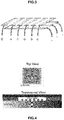
- the sensor configuration is formed by a 16x16 array with a spatial resolution of 2 cm 2 of tactile unit and a total area of 45x45 cm 2 .
- Each single sensor is formed by silver interdigitated electrodes defined by screen-printing technology on a polyethylene terephthalate (PET) flexible substrate and a poly(3,4-dioxythyophene) (PEDOT) conducting polymer on the top side of the electrodes acting as an active coating.
- PET polyethylene terephthalate
- PEDOT poly(3,4-dioxythyophene)
- An insulating acrylate elastomeric coating is used as a separator between the electrodes and the electroactive coating.
- Figure 4 shows a scheme of the sensor array (top and transversal view) and
- Figure 5 shows a picture of the 16x16 sensor array (45x45 cm 2 ).
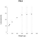
- a pressure sensor was prepared from two flexible sheets of polyethylene terephthalate (PET) of 5 cm x 5 cm of active area and 175 microns of thickness each, coated with a thin layer (1-2 microns) of poly(ethylene-dioxy-thiophene) containing as a polyanion a poly(styrene sulphonic) acid (PEDOT-PSS) deposited by oxidative polymerisation of the ethylene-dioxy-thiophene monomer in water, giving rise to a dispersion with a solid content of 2.5%.
- PET polyethylene terephthalate
- PDOT-PSS poly(styrene sulphonic) acid
- the sheets were assembled using an adhesive double-sided insulating spacer (IS) of 0.125 mm thickness in a symmetric sandwich-type configuration (PET/PEDOT-PSS/IS/PEDOT-PSS/PET), placing the spacer as a flat band 0.5 cm wide along the edges of the PEDOT-PSS-coated sheets.
- the pressure sensor thus assembled did not give any signs of current going through in the absence of pressure when a potential was applied between both sheets.
- Sensor response as current intensity measured when applying different weights upon the sensor surface and applying a potential difference of 1 V between both sheets is illustrated in Figure 6 .
- a pressure sensor was prepared from one flexible sheet of polyethylene terephthalate (PET) of 1 cm x 1 cm of active area and 175 microns of thickness each, coated with a thin layer (1-2 microns) of poly(ethylene-dioxy-thiophene) containing as a polyanion a poly(styrene sulphonic) acid (PEDOT-PSS) deposited by oxidative polymerisation of the ethylene-dioxy-thiophene monomer in water, giving rise to a dispersion with a solid content of 2.5 %.
- a matrix of points of epoxy resin was deposited upon this sheet with one of the configurations shown in Figure 7 (thickness 15 microns).
- a pressure sensor was prepared from two flexible sheets of cellulose paper (CP) of 5 cm x 5 cm of active area and 105 microns of thickness each, coated with a thin layer (1-2 microns) of poly(ethylene-dioxy-thiophene) containing as a polyanion a poly(styrene sulphonic) acid (PEDOT-PSS) deposited by oxidative polymerisation of the ethylene-dioxy-thiophene monomer in water, giving rise to a dispersion with a solid content of 2.5%.
- PEDOT-PSS poly(styrene sulphonic) acid
- the sheets were assembled using an adhesive double-sided insulating spacer (IS) of 0.125 mm thickness in a symmetric sandwich-type configuration (CP/PEDOT-PSS/IS/PEDOT-PSS/CP), placing the spacer as a flat band 0.5 cm wide along the edges of the PEDOT-PSS-coated sheets.
- the pressure sensor thus assembled did not give any signs of current going through in the absence of pressure when a potential was applied between both sheets. Sensor response as current intensity measured when applying different weights upon the sensor surface and applying a potential difference of 1 V between both sheets was similar to that obtained by the sensor in Example 1.
- the sensor device 11 may be based on distributed pressure sensors, such as flexible pressure sensors, for example, large surface distributed pressure sensors (e.g. polythiophene-based distributed pressure sensors) as described above.
- distributed pressure sensors such as flexible pressure sensors, for example, large surface distributed pressure sensors (e.g. polythiophene-based distributed pressure sensors) as described above.
- the sensor device 11 may provide electrical or electronic signals to the monitoring system 12.
- This data may be collected, for each sensor element, in the form of an electrical or electronic signal by converting the measurement of the change in resistance (or capacitance or inductance) provided by each sensor element into voltage or intensity and may be provided to the monitoring system 12.
- both the sensor device 11 and the monitoring system 12 may comprise a communications module (not shown) to establish a communication between them. If the sensor device and the monitoring system are close enough, they may be wired (for example, through Ethernet technology) or may be connected through wireless short-range communication technologies, for example, Bluetooth (e.g. BLE - Bluetooth Low Energy), NFC, Zigbee or Wi-Fi technology. If the sensor device and the monitoring system are far away, they may be connected through wireless long-range communication technologies such as GSM, GPRS, 3G, 4G, 5G or satellite technology or wired (for example, through optical fiber, ADSL, etc.).
- wireless short-range communication technologies for example, Bluetooth (e.g. BLE - Bluetooth Low Energy), NFC, Zigbee or Wi-Fi technology.
- wireless long-range communication technologies such as GSM, GPRS, 3G, 4G, 5G or satellite technology or wired (for example, through optical fiber, ADSL, etc.).
- the monitoring system 12 may comprise or may be implemented by electronic means, computing means or a combination of them, that is, said electronic or computing means may be used interchangeably so that a part of the described means may be electronic means and the other part may be computing means, or all described means may be electronic means or all described means may be computing means.
- Examples of a monitoring system 12 comprising only electronic means (that is, a purely electronic configuration) may be a programmable electronic device such as a CPLD (Complex Programmable Logic Device), an FPGA (Field Programmable Gate Array) or an ASIC (Application-Specific Integrated Circuit).
- CPLD Complex Programmable Logic Device
- FPGA Field Programmable Gate Array
- ASIC Application-Specific Integrated Circuit
- Examples of a monitoring system 12 comprising only computing means may be a computer system, which may comprise a memory and a processor, the memory being adapted to store a set of computer program instructions, and the processor being adapted to execute these instructions stored in the memory in order to generate the various events and actions for which the monitoring system has been programmed.
- the memory may be comprised in the processor (e.g. an EEPROM) or may be external.
- an external memory it can be, for example, data storage means such as magnetic disks (e.g., hard disks), optical disks (e.g., DVD or CD), memory cards, flash memory (e.g., pendrives) or solid-state drives (SSD based on RAM, based on flash, etc.).
- these storage means can be part of the monitoring system 12 itself and / or can be arranged remotely thereto, wired or wirelessly connected.
- the communication established between the monitoring system and the storage means can be ensured by, for example, username / password, cryptographic keys and / or by an SSL tunnel established in the communication between them.
- the set of computer program instructions executable by the processor may be stored in a physical storage means, such as those mentioned, but may also be carried by a carrier wave (the carrier medium). It can be any entity or device capable of carrying the program, such as electrical or optical, which can be transmitted via electrical or optical cable or by radio or other means.
- the carrier means can be constituted by said cable or another device or means.
- the computer program may be in the form of source code, object code, a code intermediate source and object code such as in partially compiled form, or in any other form suitable for use in the implementation of the method.
- the carrier may be any entity or device capable of carrying the computer program.
- the carrier may be an integrated circuit in which the computer program is embedded, the integrated circuit being adapted for performing, or for use in the performance of, the relevant methods.
- the monitoring system 12 may be based on a low-power hardware device like a microcontroller, a SoC, a PSoC (Programmable SoC) or an ASIC, although, in some scenarios, it may be possible to use other hardware like an FPGA, a CPLD (Complex Programmable Logic Device) or a DSP (Digital Signal Processor).
- the monitoring system can also contain different types of embedded memories to store data and program instructions.
- the monitoring system may include other electronic components like oscillators or programming interfaces (e.g., JTAG, ICSP). This way, the monitoring system 12 may also be implemented by using different types of electronic devices.
- CPUs Central Processing Units
- FPGAs Field-Programmable Gate Arrays
- ASIC Application-Specific Integrated Circuits
- SOCs System-On-Chips
- CPUs are powerful.
- Microcontrollers are usually used because they can be reprogrammed easily and they are powerful enough for carrying out the tasks to be performed.
- FPGAs can be really powerful for performing certain deterministic demanding tasks, but development is not as easy as with microcontrollers.
- ASICs are designed explicitly for specific applications and thus they are extremely powerful. However, the cost of developing an ASIC is really high (millions of U.S. dollars) and it only compensates when a really high amount of devices is going to be produced.
- SoCs they integrate in a single integrated circuit a powerful microcontroller and several peripherals (e.g., wireless transceivers).
- the monitoring system 12 may also have a hybrid configuration between computing and electronic means.
- the system may comprise a memory and a processor to implement computationally part of its functionalities and certain electronic circuits to implement the remaining functionalities.
- the monitoring system 12 may comprise several modules, each of which may perform a part of the events and actions for which the control module as a whole has been programmed. If the modules are close enough, they may be wired (for example, through Ethernet technology) or may be connected through wireless short-range communication technologies. If the modules are far away, they may be connected through long-range wireless communication technologies or long-range wired communication technologies. The cited technologies have been previously disclosed.
- the monitoring system 12 will be performed based on a configuration in modules.
- the monitoring system may have any of the configurations disclosed above.
- the monitoring system 12 may comprise the following modules:
- the key elements of the monitoring system 12 are the signal pre-processing module 13 and the extracting module 14. These modules pre-condition the signals received from the sensor device 11 and extract the main features that will be used as predictors. They are very important since the electrical signals produced by the sensor device are noisy, carry a big quantity of data with a variable number of items. The number of items is variable since the sampling time is not fixed, i.e. it depends on the starting and end time point of collection triggered by the user. Thus, to build the predictor, a method executed by the monitoring system 12 that produces equidimensional measurements, selects the most informative features of the measurements in both the time and spectral domain, and more importantly, builds a collection of features describing quantitatively the behaviour of the signals is designed.
- the monitoring system 12 may further comprise a module 16 for detecting whether any of the received signals coming from the sensor device 11 is wrong.
- the signal pre-processing module 13 works as a signal preconditioning interface of all the signals collected from the sensor device 11 to be digested by the rest of the modules of the monitoring system 12. This way, the objective of this module is to adapt the signals coming from the firmware of the sensor device and prepare them to be processed by the downstream modules.
- Inputs of the pre-processing module 13 are the signals coming from the sensor device 11 in the form of a tridimensional tensor N r ⁇ N c ⁇ N S of the measurement of a matrix at each time instant, where N r and N c are the number of rows and columns, respectively, of the array sensor, and N S is the number of time instants.
- the output of the pre-processing module 13 is a vector V with the preprocessed signals across all the sampling period.
- the sensor device 11 For each sampling time, the sensor device 11 produces an N r ⁇ N c measurement matrix, where N r and N c are the number of rows and columns of the array sensor.
- the sensor device 11 For each replicate r of each individual, the sensor device 11 produces a three-dimensional tensor T S of order N r ⁇ N c ⁇ N S .
- N S may be in the range of, for example, [100 280].
- the final sampling time of each replicate depends on the response time of the supervisor.
- the initial tensor T S will be reformatted using the following rules:
- This value is used to pad uniformly the N r ⁇ N c ⁇ N p elements of the padding tensor T p .
- To filter glitches other strategies different from the maximum can be used to chosen to select the padding value V p .
- N MAX may be chosen to be, for example, in the range of [180 280].
- the N r ⁇ N c ⁇ N MAX tensor T MAX is vectorized into an N MAX length vector V, in which to each position i in [1 N MAX ] is assigned the sum of the elements of the N r ⁇ N c matrix in the position i of the T MAX tensor.
- the sensor device 11 produces a resting background signal when not pressure is applied on it. Such background signal is not always the same in each case. Therefore, to avoid this effect, a background correction of the vector V is implemented.
- the background correction is implanted by subtracting from each element of V the value of the minimum element of V, V MIN .
- V MIN min 1 ⁇ i ⁇ N MAX V i
- Vb i V i ⁇ V MIN , 1 ⁇ i ⁇ N MAX
- N r may be, for example, in the range of [1 5].
- the extracting module 14 With respect to the extracting module 14, its objective is to summarize the vector V b signal (obtained previously by the pre-processing module 13) in a compact way to be more easily processed by the downstream modules.
- the vector V b has a variable length, and its signal behaves in a noise complicated way. These two features make this vector difficult for manipulation by the downstream modules.
- the transformation of this vector to a collection of descriptive variables with fixed dimensions and robust to the noise solves the aforementioned drawbacks.
- predictor variables may be selected from three categories:
- a three-dimensional scatter plot of the signal descriptive variables is given in Figure 11 .
- the following variables (A) Range, (B) Time index of the maximum peak, (Std) standard deviation, (D) Slope, (E) Start time of change of the signal, (F) Integral of the signal. All of them are depictured together with the anonymized index of the individual and the TUG (it will be disclosed later). It is possible to use an anonymized index of the individual not because it is a descriptive variable but to reduce the point overlapping effect. The Robust and Fragile cases are depicted with white and black circles (it will be disclosed later).
- V TIME are the [(length(V b ))/d] elements of the V b decimated vector: V b d .
- V P V DESCRIPTIVE
- the resulting matrix is normalized between 0 and 1.
- the module 15 for assessing the functional performance of an individual comprises a module for identifying the state of fragile or robust of the individual
- the objective of the module is to classify or identify whether an individual is fragile or robust.
- the output of the module is a bimodal class value C marking whether the individual is fragile or robust, and a value that gives the probability of the assignment.
- an Artificial Neural Network with the following topology may be used:
- transfer functions defining to calculate the output of each neuron of each layer it is possible to use the Competitive transfer function, Elliot sigmoid transfer function, Positive hard limit transfer function, Symmetric hard limit transfer function, Logarithmic sigmoid transfer function, Inverse transfer function, Positive linear transfer function, Linear transfer function, Radial basis transfer function, Radial basis normalized transfer function, Positive saturating linear transfer function, Symmetric saturating linear transfer function, Soft max transfer function, Symmetric sigmoid transfer function and Triangular basis transfer function among others.
- the Competitive transfer function Elliot sigmoid transfer function, Positive hard limit transfer function, Symmetric hard limit transfer function, Logarithmic sigmoid transfer function, Inverse transfer function, Positive linear transfer function, Linear transfer function, Radial basis transfer function, Radial basis normalized transfer function, Positive saturating linear transfer function, Symmetric saturating linear transfer function, Soft max transfer function, Symmetric sigmoid transfer function and Triangular basis transfer function among others.
- SDGM stochastic gradient descent with momentum
- backpropagation methods such as the Broyden-Fletcher-Goldfarb-Shanno (BFGS) quasi-Newton backpropagation, conjugate gradient backpropagation with Powell-Beale, Fletcher-Reeves, or Polak-Ribiere restarts, the gradient descent backpropagation, the gradient descent with adaptive Ir backpropagation, the gradient descent with momentum, the gradient descent w/momentum & adaptive Ir backpropagation, the one step secant backpropagation, the resilient backpropagation (RPROP), the scaled conjugate gradient backpropagation.
- SDGM stochastic gradient descent with momentum
- BFGS Broyden-Fletcher-Goldfarb-Shanno
- BFGS Broyden-Fletcher-Goldfarb-Shanno
- RPROP resilient backpropagation
- the input layer is feed with the collection of predictor variables V P of the training individuals and the output layer with the bimodal class value C of the training individuals.
- the input layer is feed with the collection of predictor variables V P of the test individuals and the output layer with the bimodal class value C of the test individuals.
- the result of the training of the Artificial Neural Network is shown in the confusion matrix of Figure 13 .
- Confusion matrix The rows correspond to the predicted class (predicted TUG) and the columns to the measure class (measured TUG).
- the diagonal cells show for how many (top number), and in what percentage (bottom number) of the examples the trained network estimates correctly the classes of observations, that is, it shows what percentage of the true and predicted classes match.
- the off diagonal cells show where the classifier has made mistakes, the cells in this case show for how many (top number), and in what percentage (bottom number) of the examples the trained network wrongly the classes of observations.
- the column on the far right of the table shows the accuracy for each predicted class (on top the percentage of corrected predicted in each category and on bottom the percentage of predictions that are wrong).
- the row at the bottom of the plot shows the accuracy for each true class (on top in green the percentage of corrected predicted in each category and on bottom in red the percentage of predictions that are wrong).
- the cell in the bottom right of the plot shows the overall accuracy (on top the percentage of predictions that are correct and on bottom the percentage of predictions that are wrong).
- the module 15 for assessing the functional performance of an individual comprises a module for predicting the value of the TUG (Timed Up Go) test of an individual, the objective is to predict in seconds the value of the TUG (Timed Up GO) test.
- the TUG predictor modules use as independent variables the chosen predictor variables.
- the output of the module is the measured TUG scaled between 0 and 1.
- the independent variables are used together with a unit vector of the same length as the number individuals to fit a linear regression model of the scaled TUG target.
- a multiple linear regression with the least square optimization may be used.
- TUG Reg b ⁇ V p
- TUG Pred TUG Reg ⁇ TUG Max ⁇ TUG Min ) + TUG Min where TUG Max and TUG Min are the maximum and the minimum of the measured TUG of all the individuals.
- the module 15 for assessing the functional performance of an individual may comprise a module for identifying individuals with high risk of fractures and other health related adverse outcomes. Said identification may be based on the results of the TUG test previously disclosed because there is a correlation with them. The TUG test has demonstrated the ability to identify this type of individuals.
- the input of the module is the vector V b provided by the pre-processing module 13 with the pre-processed signals across all the sampling period from the signal processing module.
- the output may be a warning signal that triggers a visual, haptic and/or a sound alarm.
- This module 16 is convenient for troubleshooting. If the person using the sensor proceeds correctly following the instructions and there are no hardware problems, this module will not generate signals. However, in the event of any manipulation error or hardware damage, the module generates a signal that will help avoid downstream problems.
- a warning may be generated, for example, by at least one of the following actuator elements:
- Figure 14 shows a first graph (A) representing time profiles after vectorization and before removal of wrong records and a second graph (B) representing time profiles after vectorization and after removal of wrong records, that is, time profiles after passing through the module 16 for detecting whether any of the received signals coming from the sensor device 11 is wrong. It is important to note that the robust and fragile cases are depicted in the graphs (A) and (B) in grey and black lines, respectively.
- the monitoring system 12 may be configured to execute a method of assessing the functional performance of an individual as described above. This way, the method may comprise:
- the method may comprise detect whether any of the received signals coming from the sensor device is wrong.
- step of pre-processing the signals received from the sensor device may comprise:
- Producing an equi-order tensor T MAX of dimensions N r ⁇ N c ⁇ N MAX may comprise:
- Pre-processing the signals received from the sensor device may further comprise correcting the background of the vector V for obtaining a background corrected vector V b .
- Correcting the background of the vector V may comprise subtracting from each element of vector V the value of the minimum element of V, V MIN , such that a background corrected vector V b is obtained.
- Extracting the main features of the pre-processed signals to be used as predictor variables, predictor variables being signal descriptive variables in the time domain may comprise obtaining the signal descriptive variables in the time domain vector V DESCRIPTIVE .
- Extracting the main features of the pre-processed signals to be used as predictor variables, predictor variables being signal time series variables in the time domain, may comprise:
- Reducing the sample length of the filtered vector V b by decimation factor of d may comprise at least of the following:
- Extracting the main features of the pre-processed signals to be used as predictor variables, predictor variables being signal spectral variables in the frequency domain, may comprise:
- Extracting, the main features of the pre-processed signals to be used as predictor variables may further comprise:
- Detecting whether any of the received signals coming from each sensor of the array of sensors is wrong may comprise:
- Detecting whether any of the received signals coming from each sensor of the array of sensors is wrong may further comprise, if a received signal is rejected, generating a warning about the rejection of the signal.
- Assessing the functional performance of an individual based on the extracted predictor variables may comprise:
- Predicting the value of the TUG (Timed Up Go) test of the individual based on the extracted predictor variables may comprise:
- Assessing the functional performance of an individual based on the extracted predictor variables may comprise identifying individuals with high risk of fractures and other health related adverse outcomes based on the extracted predictor variables.
- Identifying individuals with high risk of fractures and other health related adverse outcomes based on the extracted predictor variables may comprise:
- the monitoring system 12 may be configured to execute the described method of assessing the functional performance of an individual.
- the monitoring system 12 may comprise a memory and a processor, embodying instructions stored in the memory and executable by the processor, the instructions comprising functionality to execute the described method of assessing the functional performance of an individual.
- the invention also relates to a non-transitory computer program product that causes a managing system 12 to perform a method of assessing the functional performance of an individual.
- the invention relates to a computer-readable medium having thereon computer-executable instructions, the computer-executable instructions upon execution configuring a monitoring system 12 to perform a method of assessing the functional performance of an individual.
- Clause 1 A system for assessing the functional performance of an individual, the system comprising:
Landscapes
- Health & Medical Sciences (AREA)
- Engineering & Computer Science (AREA)
- Medical Informatics (AREA)
- Public Health (AREA)
- Life Sciences & Earth Sciences (AREA)
- Biomedical Technology (AREA)
- Pathology (AREA)
- General Health & Medical Sciences (AREA)
- Databases & Information Systems (AREA)
- Data Mining & Analysis (AREA)
- Epidemiology (AREA)
- Primary Health Care (AREA)
- Oral & Maxillofacial Surgery (AREA)
- Dentistry (AREA)
- Physics & Mathematics (AREA)
- Physiology (AREA)
- Biophysics (AREA)
- Heart & Thoracic Surgery (AREA)
- Molecular Biology (AREA)
- Surgery (AREA)
- Animal Behavior & Ethology (AREA)
- Veterinary Medicine (AREA)
- Force Measurement Appropriate To Specific Purposes (AREA)
Priority Applications (3)
| Application Number | Priority Date | Filing Date | Title |
|---|---|---|---|
| EP18382973.8A EP3671761A1 (fr) | 2018-12-21 | 2018-12-21 | Évaluation de la performance fonctionnelle d'un individu |
| PCT/EP2019/086277 WO2020127709A1 (fr) | 2018-12-21 | 2019-12-19 | Évaluation des performances fonctionnelles d'un individu |
| US17/416,400 US11908582B2 (en) | 2018-12-21 | 2019-12-19 | Assessing the functional performance of an individual |
Applications Claiming Priority (1)
| Application Number | Priority Date | Filing Date | Title |
|---|---|---|---|
| EP18382973.8A EP3671761A1 (fr) | 2018-12-21 | 2018-12-21 | Évaluation de la performance fonctionnelle d'un individu |
Publications (1)
| Publication Number | Publication Date |
|---|---|
| EP3671761A1 true EP3671761A1 (fr) | 2020-06-24 |
Family
ID=65010507
Family Applications (1)
| Application Number | Title | Priority Date | Filing Date |
|---|---|---|---|
| EP18382973.8A Pending EP3671761A1 (fr) | 2018-12-21 | 2018-12-21 | Évaluation de la performance fonctionnelle d'un individu |
Country Status (3)
| Country | Link |
|---|---|
| US (1) | US11908582B2 (fr) |
| EP (1) | EP3671761A1 (fr) |
| WO (1) | WO2020127709A1 (fr) |
Cited By (1)
| Publication number | Priority date | Publication date | Assignee | Title |
|---|---|---|---|---|
| CN116205469A (zh) * | 2023-05-05 | 2023-06-02 | 武汉理工大学 | 一种基于物理信道的船舶驾驶员活跃状态监测方法及装置 |
Families Citing this family (3)
| Publication number | Priority date | Publication date | Assignee | Title |
|---|---|---|---|---|
| CN113053113A (zh) * | 2021-03-11 | 2021-06-29 | 湖南交通职业技术学院 | 一种基于PSO-Welsch-Ridge的异常检测方法及装置 |
| CN115457970B (zh) * | 2022-09-06 | 2023-04-21 | 安徽大学 | 一种自动驾驶车内回声消除方法和系统 |
| CN118948285A (zh) * | 2024-07-26 | 2024-11-15 | 华南理工大学 | 一种人体能力评估方法 |
Citations (3)
| Publication number | Priority date | Publication date | Assignee | Title |
|---|---|---|---|---|
| EP1912051A2 (fr) | 2005-07-13 | 2008-04-16 | Fundacion Cidetec | Capteurs de pression repartis sur une grande surface, a base de polythiophenes |
| PT107553A (pt) * | 2014-03-31 | 2015-09-30 | Inst Politécnico De Bragança | Equipamento para implementar o teste de avaliação funcional ''timed up and go'' |
| US9165113B2 (en) * | 2011-10-27 | 2015-10-20 | Intel-Ge Care Innovations Llc | System and method for quantitative assessment of frailty |
Family Cites Families (2)
| Publication number | Priority date | Publication date | Assignee | Title |
|---|---|---|---|---|
| US9676098B2 (en) * | 2015-07-31 | 2017-06-13 | Heinz Hemken | Data collection from living subjects and controlling an autonomous robot using the data |
| US11253173B1 (en) * | 2017-05-30 | 2022-02-22 | Verily Life Sciences Llc | Digital characterization of movement to detect and monitor disorders |
-
2018
- 2018-12-21 EP EP18382973.8A patent/EP3671761A1/fr active Pending
-
2019
- 2019-12-19 US US17/416,400 patent/US11908582B2/en active Active
- 2019-12-19 WO PCT/EP2019/086277 patent/WO2020127709A1/fr not_active Ceased
Patent Citations (3)
| Publication number | Priority date | Publication date | Assignee | Title |
|---|---|---|---|---|
| EP1912051A2 (fr) | 2005-07-13 | 2008-04-16 | Fundacion Cidetec | Capteurs de pression repartis sur une grande surface, a base de polythiophenes |
| US9165113B2 (en) * | 2011-10-27 | 2015-10-20 | Intel-Ge Care Innovations Llc | System and method for quantitative assessment of frailty |
| PT107553A (pt) * | 2014-03-31 | 2015-09-30 | Inst Politécnico De Bragança | Equipamento para implementar o teste de avaliação funcional ''timed up and go'' |
Non-Patent Citations (1)
| Title |
|---|
| ADVANCED FUNCTIONAL MATERIALS, vol. 14, 2004, pages 615 - 622 |
Cited By (1)
| Publication number | Priority date | Publication date | Assignee | Title |
|---|---|---|---|---|
| CN116205469A (zh) * | 2023-05-05 | 2023-06-02 | 武汉理工大学 | 一种基于物理信道的船舶驾驶员活跃状态监测方法及装置 |
Also Published As
| Publication number | Publication date |
|---|---|
| US11908582B2 (en) | 2024-02-20 |
| WO2020127709A1 (fr) | 2020-06-25 |
| US20220059233A1 (en) | 2022-02-24 |
Similar Documents
| Publication | Publication Date | Title |
|---|---|---|
| US11908582B2 (en) | Assessing the functional performance of an individual | |
| EP3579091A1 (fr) | Traitement de signal de pression | |
| EP3355042B1 (fr) | Substrat d'affichage, appareil d'affichage, système de détection de pression et son procédé de détection | |
| Huang et al. | A bioinspired MXene-based flexible sensory neuron for tactile near-sensor computing | |
| Seol et al. | Hysteretic behavior of contact force response in triboelectric nanogenerator | |
| Serra et al. | Activity recognition with smart polymer floor sensor: Application to human footstep recognition | |
| EP3139255A1 (fr) | Capteur tactile et son procédé de fabrication | |
| US11294492B2 (en) | Pressure signal processing | |
| Chuang et al. | Flexible tactile sensor for the grasping control of robot fingers | |
| US12085393B2 (en) | User context and activity detection device and method | |
| CN119125926A (zh) | 电池健康状态的预测方法、装置、检测组件及车辆 | |
| KR102595386B1 (ko) | 신경회로망을 이용한 배터리의 상태 추정과 모니터링 방법 및 장치 | |
| CN108549834A (zh) | 一种基于柔性传感器的人体坐姿识别方法及其系统 | |
| CN120577710B (zh) | 一种基于神经网络的储能系统状态评估方法 | |
| CN108489643A (zh) | 一种基于人体皮肤仿生学原理的压电触觉传感器 | |
| Saadeh et al. | Evaluating and modeling force sensing resistors for low force applications | |
| EP3213040B1 (fr) | Système, procédé et dispositif de détection | |
| Wang et al. | Hypersensitive pressure sensors inspired by scorpion mechanosensory mechanisms for near-body flow detection in intelligent robots | |
| CN111459627A (zh) | 基于强化学习的智能终端传感器调度方法 | |
| US9710121B2 (en) | Position determination techniques in resistive touch screen applications | |
| CN121027853A (zh) | 用于新能源汽车电池的故障诊断系统及方法 | |
| CN208125304U (zh) | 一种基于人体皮肤仿生学原理的压电触觉传感器 | |
| Zhou et al. | Motion sensors achieved from a conducting polymer-metal Schottky contact | |
| CN117110880A (zh) | 一种用于云端-边缘端协同的电池多状态联合估计方法 | |
| CN119630949A (zh) | 使用了膜型力觉传感器的输入装置及其载荷检测方法 |
Legal Events
| Date | Code | Title | Description |
|---|---|---|---|
| PUAI | Public reference made under article 153(3) epc to a published international application that has entered the european phase |
Free format text: ORIGINAL CODE: 0009012 |
|
| STAA | Information on the status of an ep patent application or granted ep patent |
Free format text: STATUS: THE APPLICATION HAS BEEN PUBLISHED |
|
| AK | Designated contracting states |
Kind code of ref document: A1 Designated state(s): AL AT BE BG CH CY CZ DE DK EE ES FI FR GB GR HR HU IE IS IT LI LT LU LV MC MK MT NL NO PL PT RO RS SE SI SK SM TR |
|
| AX | Request for extension of the european patent |
Extension state: BA ME |
|
| STAA | Information on the status of an ep patent application or granted ep patent |
Free format text: STATUS: REQUEST FOR EXAMINATION WAS MADE |
|
| 17P | Request for examination filed |
Effective date: 20210111 |
|
| RBV | Designated contracting states (corrected) |
Designated state(s): AL AT BE BG CH CY CZ DE DK EE ES FI FR GB GR HR HU IE IS IT LI LT LU LV MC MK MT NL NO PL PT RO RS SE SI SK SM TR |
|
| RAP1 | Party data changed (applicant data changed or rights of an application transferred) |
Owner name: ADMINISTRACION GENERAL DE LA COMMUNIDAD AUTONOMA DE EUSKADI |
|
| STAA | Information on the status of an ep patent application or granted ep patent |
Free format text: STATUS: EXAMINATION IS IN PROGRESS |
|
| 17Q | First examination report despatched |
Effective date: 20230616 |