EP3671795A1 - Actionneur pour un disjoncteur moyenne tension - Google Patents
Actionneur pour un disjoncteur moyenne tension Download PDFInfo
- Publication number
- EP3671795A1 EP3671795A1 EP18214818.9A EP18214818A EP3671795A1 EP 3671795 A1 EP3671795 A1 EP 3671795A1 EP 18214818 A EP18214818 A EP 18214818A EP 3671795 A1 EP3671795 A1 EP 3671795A1
- Authority
- EP
- European Patent Office
- Prior art keywords
- stator
- rotor
- actuator according
- curvature
- actuator
- Prior art date
- Legal status (The legal status is an assumption and is not a legal conclusion. Google has not performed a legal analysis and makes no representation as to the accuracy of the status listed.)
- Granted
Links
Images


Classifications
-
- H—ELECTRICITY
- H01—ELECTRIC ELEMENTS
- H01H—ELECTRIC SWITCHES; RELAYS; SELECTORS; EMERGENCY PROTECTIVE DEVICES
- H01H33/00—High-tension or heavy-current switches with arc-extinguishing or arc-preventing means
- H01H33/60—Switches wherein the means for extinguishing or preventing the arc do not include separate means for obtaining or increasing flow of arc-extinguishing fluid
- H01H33/66—Vacuum switches
- H01H33/666—Operating arrangements
- H01H33/6662—Operating arrangements using bistable electromagnetic actuators, e.g. linear polarised electromagnetic actuators
-
- H—ELECTRICITY
- H01—ELECTRIC ELEMENTS
- H01H—ELECTRIC SWITCHES; RELAYS; SELECTORS; EMERGENCY PROTECTIVE DEVICES
- H01H3/00—Mechanisms for operating contacts
- H01H3/22—Power arrangements internal to the switch for operating the driving mechanism
- H01H3/28—Power arrangements internal to the switch for operating the driving mechanism using electromagnet
-
- H—ELECTRICITY
- H01—ELECTRIC ELEMENTS
- H01H—ELECTRIC SWITCHES; RELAYS; SELECTORS; EMERGENCY PROTECTIVE DEVICES
- H01H33/00—High-tension or heavy-current switches with arc-extinguishing or arc-preventing means
- H01H33/60—Switches wherein the means for extinguishing or preventing the arc do not include separate means for obtaining or increasing flow of arc-extinguishing fluid
- H01H33/66—Vacuum switches
- H01H33/666—Operating arrangements
-
- H—ELECTRICITY
- H02—GENERATION; CONVERSION OR DISTRIBUTION OF ELECTRIC POWER
- H02K—DYNAMO-ELECTRIC MACHINES
- H02K26/00—Machines adapted to function as torque motors, i.e. to exert a torque when stalled
Definitions
- the present invention relates to an actuator for a medium voltage circuit breaker, and to medium voltage circuit breaker having such an actuator.
- a closing operation should also be performed by a fast motion of at least one of the two poles of a phase.
- State of the art medium voltage circuit breakers use spring-driven actuators. These lack controllability.
- One potential drawback is that the mechanism is always actuated with the maximum available force, regardless of the speed requirement of a particular operation.
- a further drawback is that the operation behaviour may change under different environmental conditions and aging.
- spring-driven actuators usually consist of many moving parts, making them prone to mechanical failure.
- An electromagnetic actuator is inherently controlled, meaning that the speed of each individual operation may be controlled by means of an electronic control unit. Therefore, electromagnetic actuators have been proposed for use in medium voltage circuit breakers.
- an actuator for a medium voltage circuit breaker comprising:
- a limited angular stroke rotational actuator is provided that embraces directly the main shaft (direct drive) of a medium voltage circuit breaker. Mounting the rotational actuator directly on the main shaft of the circuit breaker avoids the use of additional linkages, thereby decreasing cost and increasing reliability. Having a limited rotational stroke enables the use of a single-phase actuator, thereby eliminating the need of a multi-phase controller, further decreasing cost and increasing reliability.
- the angle of rotation of the rotor with respect to the stator is limited by a driving electromagnetic force distribution.
- a non-zero driving electromagnetic force can only be applied for a limited range of rotational positions of the rotor.
- rotation of the rotor with respect to the stator can be limited by a mechanical stop, where for example two parts touch each other at the end of a free stroke, where at least one of those parts can be protrusion.
- a mechanical stop where for example two parts touch each other at the end of a free stroke, where at least one of those parts can be protrusion.
- stator is configured to be mounted circumferentially around the rotor.
- stator is configured to be mounted to a stationary housing of the circuit breaker.
- Stationary means that the main shaft of the circuit breaker rotates relative to the stationary housing.
- the rotor comprises a ferromagnetic material.
- the stator comprises a ferromagnetic material.
- the actuator is a reluctance motor or reluctance actuator, where a stator having a coil generates a magnetic flux when excited with electrical current that results in a non-zero torque being applied to the rotor.
- the actuator when mounted to the main shaft of the circuit breaker, the actuator is configured to move from a first unaligned position to a second aligned position where poles of the rotor and stator poles are aligned.
- rotor of the actuator moves, rather than the complete actuator assembly, and the movement is due to the electromagnetic torque, which is a result of the electrical current running in the coil or coils.
- the rotor and stator poles do not overlap.
- the rotor in moving from the first unaligned position to the second aligned position, the rotor rotates a defined amount with respect to the stator before the rotor and stator poles start to overlap.
- the maximum available torque can be obtained that accounts for inductance in the stator coil meaning that the current rises with a slope once the coil is energized. The rising current causes the rotor to rotate.
- the start unaligned position can be defined such that when the current has reached its maximum value the poles of the rotor and stator are at just at the edge of overlapping in order to maximise "starting" torque.
- an angularly constant air gap separates an outer surface of the rotor that faces an inner surface of the stator.
- the outer surface of the rotor has a radius of curvature and the inner surface of the stator pole has a radius of curvature.
- the radii of curvature share a common origin that is centred on an axis of the main shaft of the circuit breaker.
- an angularly varying air gap separates an outer surface of the rotor that faces an inner surface of the stator.
- the outer surface of the rotor has a radius of curvature and the inner surface of the stator has a radius of curvature.
- the radii of curvature do not share a common origin.
- the air gap decreases.
- a stepwise varying air gap separates an outer surface of the rotor that faces an inner surface of the stator.
- the outer surface of the rotor has a plurality of radii of curvature and the inner surface of the stator has a radius of curvature, or the outer surface of the rotor has a radius of curvature and the inner surface of the stator has a plurality of radii of curvature or the outer surface of the rotor has a plurality of radii of curvature and the inner surface of the stator has a plurality of radii of curvature.
- the radii of curvature share a common origin that is centred on an axis of the main shaft of the circuit breaker.
- the radii of curvature of the rotor and of the stator do not do not share a common origin.
- At least two of radii of curvature of the rotor do not share a common origin with each other.
- At least two of radii of curvature of the stator do not share a common origin with each other.
- the at least one coil is wound around at least a part of a first stator pole and/or the at least one coil is wound around at least a part of a second stator pole.
- the rotor comprises two parts.
- the stator comprises two parts.
- the stator is configured such that the angle of rotation of the rotor is limited with respect to the stator.
- the stator comprises at least one protrusion, wherein a first stator pole comprises a protrusion and/or a second stator pole comprises a protrusion, and wherein upon actuation as the rotor rotates, it approaches the at least one protrusion.
- a medium voltage circuit breaker with at least one vacuum interrupter each comprising moveable electrical contacts for electrical power interruption, operated via a main shaft to which is mounted an actuator according to the first aspect.
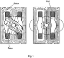
- Figs. 1-4 show actuators for a medium voltage circuit breaker as provided here, and how they can operate with a medium voltage circuit breaker.
- the actuator comprises a rotor, a stator, and a at least one coil.
- the rotor is configured to be fixedly mounted to a main shaft of a circuit breaker of a medium voltage switchgear such that the rotor and main shaft rotate together.
- the stator is configured to be mounted at least partially around the rotor.
- the at least one coil is wound around at least a part of the stator. An angle of rotation of the rotor with respect to the stator is limited.
- the angle of rotation of the rotor with respect to the stator is limited by a driving electromagnetic force distribution.
- the angle of rotation of the rotor is limited to less than one whole rotation around an axis of the main shaft.
- the stator is configured to be mounted circumferentially around the rotor.
- the stator is configured to be mounted to a stationary housing of the circuit breaker.
- the rotor comprises a ferromagnetic material.
- the stator comprises a ferromagnetic material.
- the actuator when mounted to the main shaft of the circuit breaker the actuator is configured to move from a first unaligned position to a second aligned position where poles of the rotor and stator poles are aligned.
- the unaligned position can also be considered to be a start position and the aligned position to be an end position.
- the stator pole is the part of the stator (core), around which is wound a coil.
- the rotor and stator poles do not overlap.
- the rotor in moving from the first unaligned position to the second aligned position the rotor rotates a defined amount with respect to the stator before the rotor and stator poles start to overlap.
- an angularly constant air gap separates an outer surface of the rotor that faces an inner surface of the stator.
- the outer surface of the rotor has a radius of curvature and the inner surface of the stator pole has a radius of curvature.
- the radii of curvature share a common origin that is centred on an axis of the main shaft of the circuit breaker.
- an angularly varying air gap separates an outer surface of the rotor that faces an inner surface of the stator.
- the outer surface of the rotor has a radius of curvature and the inner surface of the stator has a radius of curvature.
- the radii of curvature do not share a common origin.
- the origin of the radius of curvature of the outer surface of the rotor is the axis of main shaft or the origin of the radius of curvature of the inner surface of the stator pole is the axis of the main shaft.
- the air gap decreases.
- a stepwise varying air gap separates an outer surface of the rotor that faces an inner surface of the stator.
- the outer surface of the rotor has a plurality of radii of curvature and the inner surface of the stator has a radius of curvature, or the outer surface of the rotor has a radius of curvature and the inner surface of the stator has a plurality of radii of curvature or the outer surface of the rotor has a plurality of radii of curvature and the inner surface of the stator has a plurality of radii of curvature.
- the radii of curvature of the rotor and of the stator do not do not share a common origin.
- At least two of radii of curvature of the rotor do not share a common origin with each other.
- the stator radii can have the origin coinciding with the main rotational axis, but the radii of the rotor curvatures have two different centers elsewhere.
- At least two of radii of curvature of the stator do not share a common origin with each other.
- the rotor radii can have the origin coinciding with the main rotational axis, but the radii of the stator curvatures have two different centers elsewhere.
- the radii of curvature share a common origin that is centred on an axis of the main shaft of the circuit breaker.
- the at least one coil is wound around at least a part of a first stator pole and/or the at least one coil is wound around at least a part of a second stator pole.
- the rotor comprises two parts.
- the two parts are identical.
- the two parts are not identical.
- the rotor poles need not be identical.
- the stator comprises two parts.
- the two parts are identical.
- the two parts are not identical.
- the stator poles need not be identical.
- the stator comprises a ferromagnetic yoke configured to guide magnetic flux from a first stator pole to a second stator pole.
- the magnetic yoke of the stator extends equally in both circumferential sides of the stator. In this way, two equal magnetic paths are provided for the magnetic flux that crosses from the air gap to the stator pole.
- the magnetic yoke extends unequally on both circumferential sides of the stator. In this way, one more permeable and one less permeable path are provided for the flux. This can enable the actuator to fit into housings where the space around the main shaft is not equal on both sides.
- the yoke can connect to a stator pole only from one side, providing only a single path for the flux only on one side of the stator pole.
- the stator is configured such that the angle of rotation of the rotor is limited with respect to the stator.
- the stator comprises at least one protrusion, wherein a first stator pole comprises a protrusion and/or a second stator pole comprises a protrusion, and wherein upon actuation as the rotor rotates, it approaches the at least one protrusion.
- the figures also show a medium voltage circuit breaker with at least one vacuum interrupter, each comprising moveable electrical contacts for electrical power interruption, operated via a main shaft to which is mounted an actuator as described above.
- a rotor with magnetically salient poles embraces the main shaft and rotates together with the main shaft.
- a stator is fixed circumferential around the rotor on the stationary circuit breaker housing.
- the magnetic flux generated by one or more coils on the stator crosses through a radial air gap onto the rotor and back to complete its path.
- An electromagnetic torque generated by the magnetic flux applies on the rotor and rotates it from its initial, magnetically unaligned position to a position where the rotor and stator poles are aligned.
- the rotational stroke of the main shaft is converted to a linear motion of the moving contact via a transmission consisting of lever arms, mechanical joints and a pushrod.
- the mechanical power provided by the actuator first brings the moving contacts in contact with the fixed contacts (free travel phase), and then increases the contact force between them by charging the contact springs (contact spring compression phase).
- the stator contains at least one coil, which generates a magnetic flux when excited with electrical current. This results in a non-zero torque to apply on the rotor for a defined range of rotational angles of the rotor, where this range is less than one whole rotation around the axis (limited-stroke).
- the coils are connected electrically in series and/or parallel to form one electrical circuit (single phase).
- the total angular stroke matches the limited rotation of the main shaft of the circuit breaker.
- costly multi-phase drive electronics is avoided (as opposed to motor drives, described for example in the paper by P. Bertolotto, M. Bonaconsa, L. Chenet, M. Riva, F. Viaro: The future evolution of medium voltage circuit breakers: new developments and possible applications, CIGRE 2018, Paper A3-304 ). This decreases the cost and increases the reliability at the same time.
- Both the rotor and the stator of the actuator consist of soft ferromagnetic materials, and no permanent magnets are used.
- the actuator is a reluctance motor or a reluctance actuator.
- the lack of permanent magnets decreases the cost and can increase the robustness.
- the rotor and stator feature no eccentricity by design.
- the outermost surface of the rotor and the innermost surface of the stator poles follow two coaxial circles, the centre of both lying on the axis of the main shaft of the circuit breaker.
- the radial air gap is equal to the difference of the radii of those circles, and it is constant within the overlapping region of the rotor and stator poles both in the axial and circumferential directions.
- an eccentricity defined by the design of the rotor and stator pole shapes implies a circumferentially varying air gap.
- a decreasing radial air gap as the rotor rotates towards the aligned position results in an increase of the torque towards the end of the stroke (assuming constant current flowing in the coils).
- either one or both of the rotor and/or stator poles feature a stepwise change in their outer (for rotor) and/or inner (for stator) radii. This results in a stepwise change of the air gap as the rotor rotates rather than the continuous change described in the previous embodiment.
- the effect on the actuators torque profile is similar, but in a more stepwise fashion rather than continuous.
- the rotor is manufactured as two parts, which can be mounted on an already assembled main shaft with the help of simple nuts and bolts, without disassembling the main shaft.
- the two rotor parts are advantageously designed as identical halves.
- the stator can be manufactured in two, advantageously identical halves, both advantageously containing at least one magnetic pole of the stator.
- the magnetic yoke of the stator extends equally in both circumferential sides of the stator pole, providing two equal magnetic paths for the magnetic flux that crosses from the air gap to the stator pole.
- the yoke can extend unequally on both sides, providing one more permeable and one less permeable path for the flux. This can enable the actuator to fit into housings where the space around the main shaft is not equal on both sides.
- the yoke can connect to the stator pole only from one side, providing only a single path for the flux only on one side of the stator pole.
- stator poles themselves can be designed not to be identical.
- the circumferential thickness of the pole is defined by the required torque profile and the angular stroke.
- the height of the pole in the radial direction can be different for individual stator poles. This would be advantageous for fitting the actuator in confined spaces where the available space is unequally distributed around the main shaft.
- the torque-per-ampere ratio of the actuator is the highest at the unaligned position and reaches zero at the fully aligned position. Therefore, it is intuitive to define the starting position as the angle where rotor and stator poles do not overlap but they are positioned just at the edge of overlapping, in order to maximize the starting torque.
- the current rises with a limited slope once the coil is energized. As the current increases so does the torque, starting to rotate the rotor. This may lead to the rotor already starting to move towards the aligned position (and hence, leaving the position with highest torque-per-ampere ratio) before the current has reached its maximum value.
- the rotor's initial position can be adjusted to a position where the rotor needs to rotate a defined amount before the rotor and stator poles start overlapping.
- a protrusion of at least one of the stator poles that the rotor approaches at the end of its rotational travel can have two benefits:
- stator and rotor cores can be advantageously manufactured as isolated sheet metals (laminations), as is well known from transformers or rotary electrical machines. Individual sheet thickness can vary between 0.1mm to 2mm in typical examples. This reduces the eddy currents in the cores, thereby increasing the efficiency and the dynamic performance.
- the actuator presented here may also be manufactured using solid blocks.
Landscapes
- Physics & Mathematics (AREA)
- Electromagnetism (AREA)
- Engineering & Computer Science (AREA)
- Power Engineering (AREA)
- Iron Core Of Rotating Electric Machines (AREA)
- Driving Mechanisms And Operating Circuits Of Arc-Extinguishing High-Tension Switches (AREA)
Priority Applications (2)
| Application Number | Priority Date | Filing Date | Title |
|---|---|---|---|
| EP18214818.9A EP3671795B1 (fr) | 2018-12-20 | 2018-12-20 | Actionneur pour un disjoncteur moyenne tension |
| CN201911319774.XA CN111354580B (zh) | 2018-12-20 | 2019-12-19 | 用于中压断路器的致动器 |
Applications Claiming Priority (1)
| Application Number | Priority Date | Filing Date | Title |
|---|---|---|---|
| EP18214818.9A EP3671795B1 (fr) | 2018-12-20 | 2018-12-20 | Actionneur pour un disjoncteur moyenne tension |
Publications (2)
| Publication Number | Publication Date |
|---|---|
| EP3671795A1 true EP3671795A1 (fr) | 2020-06-24 |
| EP3671795B1 EP3671795B1 (fr) | 2024-06-19 |
Family
ID=64755265
Family Applications (1)
| Application Number | Title | Priority Date | Filing Date |
|---|---|---|---|
| EP18214818.9A Active EP3671795B1 (fr) | 2018-12-20 | 2018-12-20 | Actionneur pour un disjoncteur moyenne tension |
Country Status (2)
| Country | Link |
|---|---|
| EP (1) | EP3671795B1 (fr) |
| CN (1) | CN111354580B (fr) |
Citations (3)
| Publication number | Priority date | Publication date | Assignee | Title |
|---|---|---|---|---|
| US6674349B1 (en) * | 1999-05-20 | 2004-01-06 | Schneider Electric Industries Sa | Opening and/or closing control device, in particular for a switchgear apparatus such as a circuit breaker, and circuit breaker equipped with such a device |
| US20090058218A1 (en) * | 2007-08-30 | 2009-03-05 | Kevin Allen Bischel | Laminated rotary actuator with three-dimensional flux path |
| WO2019063104A1 (fr) * | 2017-09-29 | 2019-04-04 | Abb Schweiz Ag | Actionneur à réluctance variable |
Family Cites Families (6)
| Publication number | Priority date | Publication date | Assignee | Title |
|---|---|---|---|---|
| FR1299939A (fr) * | 1961-09-08 | 1962-07-27 | Automatic Switch Co | Moteur du type électromagnétique rotatif |
| EP1619707B1 (fr) * | 2004-07-12 | 2011-06-15 | ABB Technology AG | Contacteur sous vide pour moyenne tension |
| JP2006324399A (ja) * | 2005-05-18 | 2006-11-30 | Mitsubishi Electric Corp | アクチュエータおよびアクチュエータ駆動装置 |
| CN102770928B (zh) * | 2009-12-18 | 2015-09-30 | 施耐德电器工业公司 | 具有磁性闩锁的电磁致动器和包括一个这样的致动器的开关装置 |
| EP2704173A1 (fr) * | 2012-08-27 | 2014-03-05 | ABB Technology AG | Actionneur électromagnétique destiné à un disjoncteur sous vide à moyenne tension |
| CN103560055B (zh) * | 2013-11-16 | 2015-08-26 | 沈阳工业大学 | 一种高压断路器永磁变气隙有限转角电机操动机构 |
-
2018
- 2018-12-20 EP EP18214818.9A patent/EP3671795B1/fr active Active
-
2019
- 2019-12-19 CN CN201911319774.XA patent/CN111354580B/zh active Active
Patent Citations (3)
| Publication number | Priority date | Publication date | Assignee | Title |
|---|---|---|---|---|
| US6674349B1 (en) * | 1999-05-20 | 2004-01-06 | Schneider Electric Industries Sa | Opening and/or closing control device, in particular for a switchgear apparatus such as a circuit breaker, and circuit breaker equipped with such a device |
| US20090058218A1 (en) * | 2007-08-30 | 2009-03-05 | Kevin Allen Bischel | Laminated rotary actuator with three-dimensional flux path |
| WO2019063104A1 (fr) * | 2017-09-29 | 2019-04-04 | Abb Schweiz Ag | Actionneur à réluctance variable |
Also Published As
| Publication number | Publication date |
|---|---|
| CN111354580A (zh) | 2020-06-30 |
| CN111354580B (zh) | 2022-07-15 |
| EP3671795B1 (fr) | 2024-06-19 |
Similar Documents
| Publication | Publication Date | Title |
|---|---|---|
| US7608962B2 (en) | Electrical machine and method for setting the field and armature of a permanently excited electrical machine | |
| CN109842255B (zh) | 带有磁通可变机构的旋转电机 | |
| CN112072809B (zh) | 一种通过机械方式调节磁场的永磁旋转电枢电机 | |
| JP2009539336A (ja) | 電気的同期機械 | |
| US6674349B1 (en) | Opening and/or closing control device, in particular for a switchgear apparatus such as a circuit breaker, and circuit breaker equipped with such a device | |
| US10811941B2 (en) | Electric machine | |
| JPH0993846A (ja) | 永久磁石式同期電動機 | |
| CN111354597B (zh) | 用于中压断路器的致动器 | |
| WO2007044155A1 (fr) | Moteur à courant continu avec pôles asymétriques | |
| EP3671795B1 (fr) | Actionneur pour un disjoncteur moyenne tension | |
| EP3688864B1 (fr) | Actionneur à réluctance variable | |
| RU2330369C1 (ru) | Магнитопровод статора электрической машины | |
| KR102176372B1 (ko) | 권선 절환 가능한 전동기 | |
| JP6373776B2 (ja) | 開閉装置 | |
| RU2421865C1 (ru) | Однофазный электродвигатель | |
| EP3671784A1 (fr) | Moteur à flux hybride pour un disjoncteur moyenne tension | |
| EP2710717B1 (fr) | Moteur électrique à courant continu | |
| CN101236856B (zh) | 高压断路器圆筒型永磁直线电机操动机构 | |
| CN201364851Y (zh) | 一种高压断路器永磁摆角电机操动机构 | |
| EP2283560B1 (fr) | Machine électromécanique | |
| JP4829097B2 (ja) | 電磁アクチュエータ | |
| US11637466B1 (en) | Mechanical and electromechanical arrangements for field-weakening of an electric machine that utilizes permanent magnets | |
| JP2008017579A (ja) | 渦電流減速装置 | |
| Durairaju et al. | An alternative PM machine configuration suitable for low speed and beyond—rated speed applications | |
| KR20240000745A (ko) | 축 타입 모터의 공극 조절 장치 |
Legal Events
| Date | Code | Title | Description |
|---|---|---|---|
| PUAI | Public reference made under article 153(3) epc to a published international application that has entered the european phase |
Free format text: ORIGINAL CODE: 0009012 |
|
| STAA | Information on the status of an ep patent application or granted ep patent |
Free format text: STATUS: THE APPLICATION HAS BEEN PUBLISHED |
|
| AK | Designated contracting states |
Kind code of ref document: A1 Designated state(s): AL AT BE BG CH CY CZ DE DK EE ES FI FR GB GR HR HU IE IS IT LI LT LU LV MC MK MT NL NO PL PT RO RS SE SI SK SM TR |
|
| AX | Request for extension of the european patent |
Extension state: BA ME |
|
| STAA | Information on the status of an ep patent application or granted ep patent |
Free format text: STATUS: REQUEST FOR EXAMINATION WAS MADE |
|
| 17P | Request for examination filed |
Effective date: 20201214 |
|
| RBV | Designated contracting states (corrected) |
Designated state(s): AL AT BE BG CH CY CZ DE DK EE ES FI FR GB GR HR HU IE IS IT LI LT LU LV MC MK MT NL NO PL PT RO RS SE SI SK SM TR |
|
| STAA | Information on the status of an ep patent application or granted ep patent |
Free format text: STATUS: EXAMINATION IS IN PROGRESS |
|
| RIC1 | Information provided on ipc code assigned before grant |
Ipc: H02K 26/00 20060101ALN20220926BHEP Ipc: H01H 33/666 20060101AFI20220926BHEP |
|
| 17Q | First examination report despatched |
Effective date: 20221018 |
|
| GRAP | Despatch of communication of intention to grant a patent |
Free format text: ORIGINAL CODE: EPIDOSNIGR1 |
|
| STAA | Information on the status of an ep patent application or granted ep patent |
Free format text: STATUS: GRANT OF PATENT IS INTENDED |
|
| RIC1 | Information provided on ipc code assigned before grant |
Ipc: H02K 26/00 20060101ALN20240124BHEP Ipc: H01H 33/666 20060101AFI20240124BHEP |
|
| INTG | Intention to grant announced |
Effective date: 20240216 |
|
| GRAS | Grant fee paid |
Free format text: ORIGINAL CODE: EPIDOSNIGR3 |
|
| GRAA | (expected) grant |
Free format text: ORIGINAL CODE: 0009210 |
|
| STAA | Information on the status of an ep patent application or granted ep patent |
Free format text: STATUS: THE PATENT HAS BEEN GRANTED |
|
| AK | Designated contracting states |
Kind code of ref document: B1 Designated state(s): AL AT BE BG CH CY CZ DE DK EE ES FI FR GB GR HR HU IE IS IT LI LT LU LV MC MK MT NL NO PL PT RO RS SE SI SK SM TR |
|
| RAP3 | Party data changed (applicant data changed or rights of an application transferred) |
Owner name: ABB SCHWEIZ AG |
|
| REG | Reference to a national code |
Ref country code: GB Ref legal event code: FG4D |
|
| RIN1 | Information on inventor provided before grant (corrected) |
Inventor name: BUCHH, MARIA Inventor name: MORELLI, EMANUELE Inventor name: SCHINDLER, THORSTEN Inventor name: STAHL, THOMAS Inventor name: BREISCH, SEBASTIAN Inventor name: REUTNER, HOLGER Inventor name: MECHLER, GUENTHER Inventor name: NITSCH, CLAUS Inventor name: TUEYSUEZ, ARDA |
|
| REG | Reference to a national code |
Ref country code: CH Ref legal event code: EP |
|
| REG | Reference to a national code |
Ref country code: DE Ref legal event code: R096 Ref document number: 602018070738 Country of ref document: DE |
|
| PG25 | Lapsed in a contracting state [announced via postgrant information from national office to epo] |
Ref country code: BG Free format text: LAPSE BECAUSE OF FAILURE TO SUBMIT A TRANSLATION OF THE DESCRIPTION OR TO PAY THE FEE WITHIN THE PRESCRIBED TIME-LIMIT Effective date: 20240619 |
|
| PG25 | Lapsed in a contracting state [announced via postgrant information from national office to epo] |
Ref country code: FI Free format text: LAPSE BECAUSE OF FAILURE TO SUBMIT A TRANSLATION OF THE DESCRIPTION OR TO PAY THE FEE WITHIN THE PRESCRIBED TIME-LIMIT Effective date: 20240619 Ref country code: HR Free format text: LAPSE BECAUSE OF FAILURE TO SUBMIT A TRANSLATION OF THE DESCRIPTION OR TO PAY THE FEE WITHIN THE PRESCRIBED TIME-LIMIT Effective date: 20240619 |
|
| REG | Reference to a national code |
Ref country code: LT Ref legal event code: MG9D |
|
| PG25 | Lapsed in a contracting state [announced via postgrant information from national office to epo] |
Ref country code: GR Free format text: LAPSE BECAUSE OF FAILURE TO SUBMIT A TRANSLATION OF THE DESCRIPTION OR TO PAY THE FEE WITHIN THE PRESCRIBED TIME-LIMIT Effective date: 20240920 |
|
| PG25 | Lapsed in a contracting state [announced via postgrant information from national office to epo] |
Ref country code: LV Free format text: LAPSE BECAUSE OF FAILURE TO SUBMIT A TRANSLATION OF THE DESCRIPTION OR TO PAY THE FEE WITHIN THE PRESCRIBED TIME-LIMIT Effective date: 20240619 |
|
| PG25 | Lapsed in a contracting state [announced via postgrant information from national office to epo] |
Ref country code: NO Free format text: LAPSE BECAUSE OF FAILURE TO SUBMIT A TRANSLATION OF THE DESCRIPTION OR TO PAY THE FEE WITHIN THE PRESCRIBED TIME-LIMIT Effective date: 20240919 Ref country code: LV Free format text: LAPSE BECAUSE OF FAILURE TO SUBMIT A TRANSLATION OF THE DESCRIPTION OR TO PAY THE FEE WITHIN THE PRESCRIBED TIME-LIMIT Effective date: 20240619 Ref country code: HR Free format text: LAPSE BECAUSE OF FAILURE TO SUBMIT A TRANSLATION OF THE DESCRIPTION OR TO PAY THE FEE WITHIN THE PRESCRIBED TIME-LIMIT Effective date: 20240619 Ref country code: GR Free format text: LAPSE BECAUSE OF FAILURE TO SUBMIT A TRANSLATION OF THE DESCRIPTION OR TO PAY THE FEE WITHIN THE PRESCRIBED TIME-LIMIT Effective date: 20240920 Ref country code: FI Free format text: LAPSE BECAUSE OF FAILURE TO SUBMIT A TRANSLATION OF THE DESCRIPTION OR TO PAY THE FEE WITHIN THE PRESCRIBED TIME-LIMIT Effective date: 20240619 Ref country code: BG Free format text: LAPSE BECAUSE OF FAILURE TO SUBMIT A TRANSLATION OF THE DESCRIPTION OR TO PAY THE FEE WITHIN THE PRESCRIBED TIME-LIMIT Effective date: 20240619 Ref country code: RS Free format text: LAPSE BECAUSE OF FAILURE TO SUBMIT A TRANSLATION OF THE DESCRIPTION OR TO PAY THE FEE WITHIN THE PRESCRIBED TIME-LIMIT Effective date: 20240919 |
|
| PG25 | Lapsed in a contracting state [announced via postgrant information from national office to epo] |
Ref country code: NL Free format text: LAPSE BECAUSE OF FAILURE TO SUBMIT A TRANSLATION OF THE DESCRIPTION OR TO PAY THE FEE WITHIN THE PRESCRIBED TIME-LIMIT Effective date: 20240619 |
|
| REG | Reference to a national code |
Ref country code: AT Ref legal event code: MK05 Ref document number: 1696494 Country of ref document: AT Kind code of ref document: T Effective date: 20240619 |
|
| PG25 | Lapsed in a contracting state [announced via postgrant information from national office to epo] |
Ref country code: NL Free format text: LAPSE BECAUSE OF FAILURE TO SUBMIT A TRANSLATION OF THE DESCRIPTION OR TO PAY THE FEE WITHIN THE PRESCRIBED TIME-LIMIT Effective date: 20240619 |
|
| PG25 | Lapsed in a contracting state [announced via postgrant information from national office to epo] |
Ref country code: PT Free format text: LAPSE BECAUSE OF FAILURE TO SUBMIT A TRANSLATION OF THE DESCRIPTION OR TO PAY THE FEE WITHIN THE PRESCRIBED TIME-LIMIT Effective date: 20241021 |
|
| PG25 | Lapsed in a contracting state [announced via postgrant information from national office to epo] |
Ref country code: PT Free format text: LAPSE BECAUSE OF FAILURE TO SUBMIT A TRANSLATION OF THE DESCRIPTION OR TO PAY THE FEE WITHIN THE PRESCRIBED TIME-LIMIT Effective date: 20241021 |
|
| PG25 | Lapsed in a contracting state [announced via postgrant information from national office to epo] |
Ref country code: PL Free format text: LAPSE BECAUSE OF FAILURE TO SUBMIT A TRANSLATION OF THE DESCRIPTION OR TO PAY THE FEE WITHIN THE PRESCRIBED TIME-LIMIT Effective date: 20240619 |
|
| PG25 | Lapsed in a contracting state [announced via postgrant information from national office to epo] |
Ref country code: EE Free format text: LAPSE BECAUSE OF FAILURE TO SUBMIT A TRANSLATION OF THE DESCRIPTION OR TO PAY THE FEE WITHIN THE PRESCRIBED TIME-LIMIT Effective date: 20240619 |
|
| PG25 | Lapsed in a contracting state [announced via postgrant information from national office to epo] |
Ref country code: IS Free format text: LAPSE BECAUSE OF FAILURE TO SUBMIT A TRANSLATION OF THE DESCRIPTION OR TO PAY THE FEE WITHIN THE PRESCRIBED TIME-LIMIT Effective date: 20241019 Ref country code: AT Free format text: LAPSE BECAUSE OF FAILURE TO SUBMIT A TRANSLATION OF THE DESCRIPTION OR TO PAY THE FEE WITHIN THE PRESCRIBED TIME-LIMIT Effective date: 20240619 |
|
| PG25 | Lapsed in a contracting state [announced via postgrant information from national office to epo] |
Ref country code: CZ Free format text: LAPSE BECAUSE OF FAILURE TO SUBMIT A TRANSLATION OF THE DESCRIPTION OR TO PAY THE FEE WITHIN THE PRESCRIBED TIME-LIMIT Effective date: 20240619 |
|
| PG25 | Lapsed in a contracting state [announced via postgrant information from national office to epo] |
Ref country code: RO Free format text: LAPSE BECAUSE OF FAILURE TO SUBMIT A TRANSLATION OF THE DESCRIPTION OR TO PAY THE FEE WITHIN THE PRESCRIBED TIME-LIMIT Effective date: 20240619 Ref country code: SK Free format text: LAPSE BECAUSE OF FAILURE TO SUBMIT A TRANSLATION OF THE DESCRIPTION OR TO PAY THE FEE WITHIN THE PRESCRIBED TIME-LIMIT Effective date: 20240619 |
|
| PG25 | Lapsed in a contracting state [announced via postgrant information from national office to epo] |
Ref country code: SM Free format text: LAPSE BECAUSE OF FAILURE TO SUBMIT A TRANSLATION OF THE DESCRIPTION OR TO PAY THE FEE WITHIN THE PRESCRIBED TIME-LIMIT Effective date: 20240619 Ref country code: ES Free format text: LAPSE BECAUSE OF FAILURE TO SUBMIT A TRANSLATION OF THE DESCRIPTION OR TO PAY THE FEE WITHIN THE PRESCRIBED TIME-LIMIT Effective date: 20240619 |
|
| PG25 | Lapsed in a contracting state [announced via postgrant information from national office to epo] |
Ref country code: SM Free format text: LAPSE BECAUSE OF FAILURE TO SUBMIT A TRANSLATION OF THE DESCRIPTION OR TO PAY THE FEE WITHIN THE PRESCRIBED TIME-LIMIT Effective date: 20240619 Ref country code: SK Free format text: LAPSE BECAUSE OF FAILURE TO SUBMIT A TRANSLATION OF THE DESCRIPTION OR TO PAY THE FEE WITHIN THE PRESCRIBED TIME-LIMIT Effective date: 20240619 Ref country code: RO Free format text: LAPSE BECAUSE OF FAILURE TO SUBMIT A TRANSLATION OF THE DESCRIPTION OR TO PAY THE FEE WITHIN THE PRESCRIBED TIME-LIMIT Effective date: 20240619 Ref country code: PL Free format text: LAPSE BECAUSE OF FAILURE TO SUBMIT A TRANSLATION OF THE DESCRIPTION OR TO PAY THE FEE WITHIN THE PRESCRIBED TIME-LIMIT Effective date: 20240619 Ref country code: IS Free format text: LAPSE BECAUSE OF FAILURE TO SUBMIT A TRANSLATION OF THE DESCRIPTION OR TO PAY THE FEE WITHIN THE PRESCRIBED TIME-LIMIT Effective date: 20241019 Ref country code: ES Free format text: LAPSE BECAUSE OF FAILURE TO SUBMIT A TRANSLATION OF THE DESCRIPTION OR TO PAY THE FEE WITHIN THE PRESCRIBED TIME-LIMIT Effective date: 20240619 Ref country code: EE Free format text: LAPSE BECAUSE OF FAILURE TO SUBMIT A TRANSLATION OF THE DESCRIPTION OR TO PAY THE FEE WITHIN THE PRESCRIBED TIME-LIMIT Effective date: 20240619 Ref country code: CZ Free format text: LAPSE BECAUSE OF FAILURE TO SUBMIT A TRANSLATION OF THE DESCRIPTION OR TO PAY THE FEE WITHIN THE PRESCRIBED TIME-LIMIT Effective date: 20240619 Ref country code: AT Free format text: LAPSE BECAUSE OF FAILURE TO SUBMIT A TRANSLATION OF THE DESCRIPTION OR TO PAY THE FEE WITHIN THE PRESCRIBED TIME-LIMIT Effective date: 20240619 |
|
| REG | Reference to a national code |
Ref country code: DE Ref legal event code: R097 Ref document number: 602018070738 Country of ref document: DE |
|
| PG25 | Lapsed in a contracting state [announced via postgrant information from national office to epo] |
Ref country code: DK Free format text: LAPSE BECAUSE OF FAILURE TO SUBMIT A TRANSLATION OF THE DESCRIPTION OR TO PAY THE FEE WITHIN THE PRESCRIBED TIME-LIMIT Effective date: 20240619 |
|
| PLBE | No opposition filed within time limit |
Free format text: ORIGINAL CODE: 0009261 |
|
| STAA | Information on the status of an ep patent application or granted ep patent |
Free format text: STATUS: NO OPPOSITION FILED WITHIN TIME LIMIT |
|
| 26N | No opposition filed |
Effective date: 20250320 |
|
| PG25 | Lapsed in a contracting state [announced via postgrant information from national office to epo] |
Ref country code: MC Free format text: LAPSE BECAUSE OF FAILURE TO SUBMIT A TRANSLATION OF THE DESCRIPTION OR TO PAY THE FEE WITHIN THE PRESCRIBED TIME-LIMIT Effective date: 20240619 |
|
| REG | Reference to a national code |
Ref country code: CH Ref legal event code: PL |
|
| PG25 | Lapsed in a contracting state [announced via postgrant information from national office to epo] |
Ref country code: LU Free format text: LAPSE BECAUSE OF NON-PAYMENT OF DUE FEES Effective date: 20241220 |
|
| GBPC | Gb: european patent ceased through non-payment of renewal fee |
Effective date: 20241220 |
|
| PG25 | Lapsed in a contracting state [announced via postgrant information from national office to epo] |
Ref country code: SE Free format text: LAPSE BECAUSE OF FAILURE TO SUBMIT A TRANSLATION OF THE DESCRIPTION OR TO PAY THE FEE WITHIN THE PRESCRIBED TIME-LIMIT Effective date: 20240619 |
|
| REG | Reference to a national code |
Ref country code: BE Ref legal event code: MM Effective date: 20241231 |
|
| PG25 | Lapsed in a contracting state [announced via postgrant information from national office to epo] |
Ref country code: GB Free format text: LAPSE BECAUSE OF NON-PAYMENT OF DUE FEES Effective date: 20241220 Ref country code: BE Free format text: LAPSE BECAUSE OF NON-PAYMENT OF DUE FEES Effective date: 20241231 |
|
| PG25 | Lapsed in a contracting state [announced via postgrant information from national office to epo] |
Ref country code: CH Free format text: LAPSE BECAUSE OF NON-PAYMENT OF DUE FEES Effective date: 20241231 |
|
| PG25 | Lapsed in a contracting state [announced via postgrant information from national office to epo] |
Ref country code: IE Free format text: LAPSE BECAUSE OF NON-PAYMENT OF DUE FEES Effective date: 20241220 |
|
| PGFP | Annual fee paid to national office [announced via postgrant information from national office to epo] |
Ref country code: DE Payment date: 20251211 Year of fee payment: 8 |
|
| PGFP | Annual fee paid to national office [announced via postgrant information from national office to epo] |
Ref country code: IT Payment date: 20251223 Year of fee payment: 8 |
|
| PGFP | Annual fee paid to national office [announced via postgrant information from national office to epo] |
Ref country code: FR Payment date: 20251229 Year of fee payment: 8 |