EP3671796B1 - Ensemble projectile et dispositif d'interruption de circuit électrique - Google Patents
Ensemble projectile et dispositif d'interruption de circuit électrique Download PDFInfo
- Publication number
- EP3671796B1 EP3671796B1 EP18846279.0A EP18846279A EP3671796B1 EP 3671796 B1 EP3671796 B1 EP 3671796B1 EP 18846279 A EP18846279 A EP 18846279A EP 3671796 B1 EP3671796 B1 EP 3671796B1
- Authority
- EP
- European Patent Office
- Prior art keywords
- cut
- connection terminal
- surface portion
- connection
- cut portion
- Prior art date
- Legal status (The legal status is an assumption and is not a legal conclusion. Google has not performed a legal analysis and makes no representation as to the accuracy of the status listed.)
- Active
Links
Images



Classifications
-
- H—ELECTRICITY
- H01—ELECTRIC ELEMENTS
- H01H—ELECTRIC SWITCHES; RELAYS; SELECTORS; EMERGENCY PROTECTIVE DEVICES
- H01H39/00—Switching devices actuated by an explosion produced within the device and initiated by an electric current
- H01H39/006—Opening by severing a conductor
-
- H—ELECTRICITY
- H01—ELECTRIC ELEMENTS
- H01H—ELECTRIC SWITCHES; RELAYS; SELECTORS; EMERGENCY PROTECTIVE DEVICES
- H01H39/00—Switching devices actuated by an explosion produced within the device and initiated by an electric current
-
- B—PERFORMING OPERATIONS; TRANSPORTING
- B29—WORKING OF PLASTICS; WORKING OF SUBSTANCES IN A PLASTIC STATE IN GENERAL
- B29C—SHAPING OR JOINING OF PLASTICS; SHAPING OF MATERIAL IN A PLASTIC STATE, NOT OTHERWISE PROVIDED FOR; AFTER-TREATMENT OF THE SHAPED PRODUCTS, e.g. REPAIRING
- B29C45/00—Injection moulding, i.e. forcing the required volume of moulding material through a nozzle into a closed mould; Apparatus therefor
- B29C45/14—Injection moulding, i.e. forcing the required volume of moulding material through a nozzle into a closed mould; Apparatus therefor incorporating preformed parts or layers, e.g. injection moulding around inserts or for coating articles
- B29C45/14549—Coating rod-like, wire-like or belt-like articles
-
- H—ELECTRICITY
- H01—ELECTRIC ELEMENTS
- H01H—ELECTRIC SWITCHES; RELAYS; SELECTORS; EMERGENCY PROTECTIVE DEVICES
- H01H39/00—Switching devices actuated by an explosion produced within the device and initiated by an electric current
- H01H2039/008—Switching devices actuated by an explosion produced within the device and initiated by an electric current using the switch for a battery cutoff
-
- H—ELECTRICITY
- H01—ELECTRIC ELEMENTS
- H01H—ELECTRIC SWITCHES; RELAYS; SELECTORS; EMERGENCY PROTECTIVE DEVICES
- H01H2229/00—Manufacturing
- H01H2229/044—Injection moulding
Definitions
- the present invention relates to an electric circuit breaker device that can be used in an electric circuit of a vehicle, an electric home appliance, and the like, and a method of manufacturing a component used therein.
- An electric circuit breaker device that breaks an electric circuit is used to prevent significant damage when an abnormality occurs in an electric circuit or a system including the electric circuit of a vehicle, an electric home appliance, or the like. Electric circuit breaker devices for electric circuits of electric vehicles are becoming increasingly important.
- a known electric circuit breaker device includes, in a housing, an igniter, a projectile (piston), a conductor, and the like ( US 2005/0083164 A , US 2005/0083165 A , US 2012/0234162 A , JP H11-232979 A , JP 2014-49300 A ).
- US 2005/0083164 A US 2005/0083165 A , metal, ceramic, and polymer are cited as examples of the material of a housing, and it is stated that a specific polymer is preferred ( US 2005/0083164 A pages 2 to 3, US 2005/0083165 A page 2).
- a casing 13 is made of stainless steel (paragraph number 0011).
- a case 30 has electric insulation properties, and is formed of a high-strength material (e.g., resin material) (paragraph number 0034).
- a high-strength material e.g., resin material
- US 2013/126326 A1 describes an electric circuit breaker device comprising a housing made of synthetic resin, an igniter, a resin projectile, and a conductor portion that forms a portion of an electric circuit, a bottom clip made of synthetic resin comprising a recess portion that forms an insulation space which is formed by the recess portion of the bottom clip closing off the housing, wherein the conductor portion comprises a cut portion that is orientated orthogonal to the housing and disposed facing the insulation space.
- Another embodiment of the present invention relates to a method of manufacturing this electric circuit breaker device.
- Another embodiment of the present invention relates to a method of manufacturing this electric circuit breaker device.
- Another embodiment of the present invention relates to a method of manufacturing this electric circuit breaker device.
- a method according to an embodiment of the present invention of manufacturing the cut composite of the electric circuit breaker device of the first embodiment comprising the projectile, the cut portion, the first connection portion, and the second connection portion formed integrally together comprises:
- a method according to an embodiment of the present invention of manufacturing the second composite of the electric circuit breaker device of the second embodiment comprising the projectile, the cut portion, the first connection portion, the second connection portion, and the bottom clip formed integrally together comprises:
- a method according to an embodiment of the present invention of manufacturing the third composite of the electric circuit breaker device of the third embodiment comprising the projectile, the cut portion, the first connection portion, the second connection portion, and the inner wall surface of the cylindrical space of the housing formed integrally together comprises:
- the present invention provides an electric circuit breaker device in which a conductor portion including a plurality of components are assembled together is used, the conductor portion being easily cut due to the components of the conductor portion being connected via resin, and a method of manufacturing a composite used therein.
- the housing is made of synthetic resin, and the external shape is appropriately selected according to the attachment portion.
- the housing has a shape, structure, and size that allows components such as the igniter, the projectile, the cylinder, and the conductor portion to be housed and installed therein.
- the igniter may be a known igniter used in electric circuit breaker devices or may be an igniter used as a gas igniter of an airbag device in a vehicle.
- the igniter includes an ignition portion including an ignition charge and a conduction pin for conducting electricity. At the time of actuation, the igniter combusts the ignition charge by applying electric power from an external power source, and generates combustion products such as combustion gas and flames.
- the bottom clip preferably is made of the same resin as the housing is and includes the recess portion that forms the insulation space.
- the bottom clip and the housing are integrally formed around the conductors with the opening portion of the recess portion of the bottom clip and the opening portion of the cylindrical space of the housing.
- the electric circuit breaker device of the first embodiment includes a cut composite including a projectile made of synthetic resin, a cut portion, a first connection portion, and a second connection portion formed integrally together.
- the projectile and the conductor portion are fixed together by the first fixing pin of the projectile being inserted in the first through hole of the cut portion and the first attachment hole of the first connection portion (first connection terminal) and, in this state, the end portion being deformed and by the second fixing pin of the projectile being inserted in the second through hole of the cut portion and the second attachment hole of the second connection portion (second connection terminal) and, in this state, the end portion being deformed.
- the first side surface portion of the cut portion and the first connection terminal are connected, forming two layers in the thickness direction, and the second side surface portion of the cut portion and the second connection terminal are connected, forming two layers in the thickness direction.
- the first through hole and the second through hole of the cut portion may have a constant inner diameter or the diameter may continuously increase from one to the other.
- the first attachment hole of the first connection terminal and the second attachment hole of the second connection terminal may have a constant inner diameter or the diameter may continuously increase from one to the other.
- the inner diameter of the first through hole and the second through hole of the cut portion, the inner diameter of the first attachment hole of the first connection terminal, and the inner diameter of the second attachment hole of the second connection terminal may be the same diameter.
- the diameter of the hole formed continuously increases from the first through hole toward the first attachment hole
- the diameter of the hole formed continuously increases from the second through hole toward the second attachment hole.
- the first fixing pin and the second fixing pin is given a shape that corresponds to the shape of the formed hole. This increases the bonding strength.
- the first fixing pin includes a first cylinder portion on the first side surface portion side and a first end increased diameter portion on the end side.
- the outer diameter of the first cylinder portion is less than the outer diameter of the first end increased diameter portion.
- the first end increased diameter portion is a portion given a large outer diameter by deforming the end portion of the first cylinder portion.
- the second fixing pin includes a second cylinder portion on the second side surface portion side and a second end increased diameter portion on the end side.
- the outer diameter of the second cylinder portion is less than the outer diameter of the second end increased diameter portion.
- the second end increased diameter portion is a portion given a large outer diameter by deforming the end portion of the second cylinder portion.
- the end portion of the first fixing pin and the end portion of the second fixing pin is squashed by force being applied, deformed by being squashed after being melted via heat, or squashed by force and heat being applied.
- the cut portion and the first connection portion are joined by the synthetic resin first fixing pin, and the cut portion and the second connection portion are joined by the synthetic resin second fixing pin.
- the synthetic resin pin is broken, cutting apart the cut portion and the first connection portion and cutting apart the cut portion and the second connection portion.
- This allows the cutting be achieved by a smaller force than in a configuration in which a wholly metal cut portion of the conductor portion is cut.
- the width of the portion where the notch portion is formed is narrow.
- the electric circuit breaker device of the second embodiment is different from the first embodiment in that it includes the second composite that includes the projectile, the cut portion, the first connection portion, and the second connection portion integrally formed also with the inner wall surface of the recess portion of the bottom clip.
- the projectile and the cut portion are integrally formed together and the first connection portion and the second connection portion are joined to the cut portion via the first fixing pin and the second fixing pin of the projectile.
- the electric circuit breaker device of the third embodiment is different from the first embodiment in that it includes the third composite that includes the projectile, the cut portion, the first connection portion, and the second connection portion integrally formed also with the inner wall surface of the cylindrical space of the housing.
- the projectile and the cut portion are integrally formed together and the first connection portion and the second connection portion are joined to the cut portion via the first fixing pin and the second fixing pin of the projectile.
- the conductor portion can be easily cut and the output of the igniter required to cut the conductor portion can be reduced, allowing the size of the igniter and the electric circuit breaker device to be reduced. Also, a fragile portion such as a notch does not need to be formed in the conductor portion. This reduces the problem of heat build-up in the fragile portion upon actuation.
- FIG. 1 and FIG. 2 An electric circuit breaker device 1 according to an embodiment of the present invention will be described with reference to FIG. 1 and FIG. 2 .
- the electric circuit breaker device 1 illustrated in FIG. 1C includes a cut composite 10 disposed inside an assembly of a housing 51 and a bottom clip 60.
- the cut composite 10 includes a projectile 30 and a conductor portion (a cut portion 20, a first connection portion 40, and a second connection portion 45) integrally formed together.
- the housing 51 and the bottom clip 60 are both made of synthetic resin.
- the projectile 30 is made of synthetic resin and includes an end surface 31 with a quadrangular shape, with a first side surface portion 32 and a second side surface portion 33 connected to opposing edges of the end surface 31.
- the projectile 30 also includes a first fixing pin 35 and a second fixing pin 36 jutting out from the first side surface portion 32 and the second side surface portion 33, respectively.
- the shape of the end surface 31 is preferably a square or a rectangle.
- the first fixing pin 35 includes a first cylinder portion 35a on the first side surface portion 32 side and a first end increased diameter portion 35b on the end side.
- the outer diameter of the first cylinder portion 35a is less than the outer diameter of the first end increased diameter portion 35b.
- the second fixing pin 36 includes a second cylinder portion 36a on the second side surface portion 33 side and a second end increased diameter portion 36b on the end side.
- the outer diameter of the second cylinder portion 36a is less than the outer diameter of the second end increased diameter portion 36b.
- a conductor portion is a plate portion including the first connection portion 40 and the second connection portion 45 on opposite sides and the cut portion 20 as an intermediate portion.
- the conductor portion is configured to form a portion of the electric circuit when the electric circuit breaker device 1 is part of an electric circuit.
- the first connection portion 40 and the second connection portion 45 are configured to connect to other conductors in the electric circuit (e.g., a lead wire).
- the cut portion 20 is configured to be cut and interrupt the electric circuit when activated.
- the cut portion 20 includes a flat surface portion 21 with a quadrangular shape, a first cut portion side surface portion 22 and a second cut portion side surface portion 23 extending down in the same direction from opposing edges of the flat surface portion 21 with the quadrangular shape, and a first through hole 22a and a second through hole 23a formed in the thickness direction of the first cut portion side surface portion 22 and the second cut portion side surface portion 23, respectively.
- the flat surface portion 21 with the quadrangular shape preferably has a square shape or a rectangular shape.
- the shape of the quadrangular may be the same as the shape of the end surface 31 or different.
- the width of the flat surface portion 21 with the quadrangular shape is preferably less than the width of the end surface 31 to ensure that it is easily cut.
- the flat surface portion 21 has a rectangular shape and the end surface 31 has a square shape, and the length of the short sides of the rectangular shape is less than the length of the sides of the square shape.
- the cut portion 20 does not require a fragile portion such as a notch to make it easier to cut.
- the first connection portion 40 includes a first flat portion 41 with a rectangular shape as seen in a plan view, a first connection terminal 42 extending down from one of opposing short side edges of the first flat portion 41.
- the first connection terminal 42 includes a first attachment hole 43 formed through the first connection terminal 42 in the thickness direction.
- the second connection portion 45 includes a second flat portion 46 with a rectangular shape as seen in a plan view, a second connection terminal 47 extending down from one of opposing short side edges of the second flat portion 46.
- the second connection terminal 47 includes a second attachment hole 48 formed through the second connection terminal 47 in the thickness direction.
- the cut composite 10 includes the cut portion 20 and the projectile 30 integrally formed together and the first connection portion 40 and the second connection portion 45 joined thereto.
- the cut portion 20 and the projectile 30 are integrally formed together in the following manner: the flat surface portion 21 of the cut portion 20 is in contact with the end surface 31 of the projectile 30, the first through hole 22a of the first cut portion side surface portion 22 of the cut portion 20 is placed on the first cylinder portion 35a of the first fixing pin 35 formed on the first side surface portion 32 of the projectile 30, and the second through hole 23a of the second cut portion side surface portion 23 of the cut portion 20 is placed on the second cylinder portion 36a of the second fixing pin 36 formed on the second side surface portion 33 of the projectile 30.
- the first attachment hole 43 of the first connection terminal 42 is placed over the first through hole 22a of the cut portion 20 placed on the first cylinder portion 35a of the first fixing pin 35.
- the first surface 42a of the first connection terminal 42 and the first cut portion side surface portion 22 of the cut portion 20 being in contact with one another and an inner surface of the first end increased diameter portion 35b being pressed onto a second surface 42b of the first connection terminal 42, the cut portion 20 and the first connection terminal 42 are electrically connected.
- the first end increased diameter portion 35b pushes against the first connection terminal 42 from the outside.
- the second attachment hole 48 of the second connection terminal 47 is placed over the second through hole 23a of the cut portion 20 placed on the first cylinder portion 36a of the second fixing pin 36.
- a first surface 47a of the second connection terminal 47 and the second cut portion side surface portion 23 of the cut portion 20 being in contact with one another and an inner surface of the second end increased diameter portion 36 being pressed onto a second surface 47b of the second connection terminal 47, the cut portion 20 and the second connection terminal 47 are electrically connected.
- the second end increased diameter portion 36b pushes against the second connection terminal 47 from the outside.
- FIG. 1B illustrates an embodiment in which the first through hole 22a of the cut portion 20 and the first attachment hole 43 of the first connection terminal 42 are aligned with the hole continuously increasing in diameter from the first through hole 22a toward the first attachment hole 43.
- the second through hole 23a and the second attachment hole 48 are also aligned with the hole increasing in diameter from the second through hole 23a toward the second attachment hole 48.
- a process of forming the first end increased diameter portion 35b and the second end increased diameter portion 36b is not necessary, and a portion corresponding to the first end increased diameter portion 35b and the second end increased diameter portion 36b can be made via injection molding.
- an igniter 52 and the cut composite 10 are disposed in that order from a first end portion 50a side of a cylindrical space 55 of the housing 51 toward an axially opposite second end portion 50b side.
- the bottom clip 60 is disposed on the side of the cut composite 10 opposite to where the igniter 52 is disposed.
- the bottom clip 60 is made of synthetic resin and includes a recess portion 61.
- a connector insertion space 53 is formed between the igniter 52 and the first end portion 50a.
- An opening of the recess portion 61 of the bottom clip 60 is closed by the housing 51, forming an insulation space 62.
- the insulation space 62 is where the cut portion 20 is held after being cut off upon activation.
- the housing 51 and the bottom clip 60 can be manufactured, for example, by an assembly of the housing 51, the igniter 52, and the cut composite 10 being disposed in a mold and then subjected to injection molding to form the bottom clip 60, or by integrally forming together an assembly of the housing 51, the igniter 52, and the cut composite 10 with the bottom clip 60 via an adhesive or the like.
- the cut portion 20 of the cut composite 10 is orientated orthogonal to the housing 51 (the bottom clip 60) and disposed facing the insulation space 62.
- a cylinder may be disposed between the igniter 52 and the housing 51.
- the cylinder used can be a partially modified cylinder of that illustrated in FIG. 1 and FIG. 2 of JP 2016-85947 A , for example.
- the electric circuit breaker device 1 illustrated in FIG. 1C when disposed in the electric circuit of an electric vehicle is described.
- the electric circuit breaker device 1 illustrated in FIGS. 1A to 1C together with an abnormal-current detecting sensor and the like, can automatically actuate when an abnormal current flows through the electric circuit and can also be actuated by a human action.
- the conductor portion i.e., the first connection portion 40 and the second connection portion 45, are configured to connect to the lead wire that forms the electric circuit.
- the igniter 52 activates and a combustion product containing combustion gas is produced from an igniter portion. The combustion product produced from the igniter portion impacts against the projectile 30 of the cut composite 10.
- the pressure from the combustion product acts on the projectile 30, making it move in the axial direction.
- This cuts the first fixing pin 35 joining together the cut portion 20 and the first connection portion 40 and cuts the second fixing pin 36 joining together the cut portion 20 and the second connection portion 45.
- the resin first fixing pin 35 and the resin second fixing pin 36 are cut. In this way, the output of the igniter 52 required to cut can be decreased.
- the insulation space 62 is closed off by the integral cut portion 20 and the projectile 30, preventing the cut portion 20 from returning to its original position. This action breaks the electric connection between the first connection portion 40 and the second connection portion 45, and the electric circuit including the electric circuit breaker device 1 is interrupted.
- a first method of manufacturing the cut composite 10 illustrated in FIG. 1A will be described with reference to FIG. 1 and FIG. 2 .
- the cut portion 20 (integrally formed with the projectile 30) illustrated in FIG. 2A is disposed in a mold.
- the resin for forming the projectile 30 is injection molded, the flat surface portion 21 of the cut portion 20 is brought in contact with the end surface 31 of the projectile 30, the first through hole 22a of the first cut portion side surface portion 22 of the cut portion 20 is placed on the first fixing pin 35 of the first side surface portion 32 of the projectile 30, and the second through hole 23a of the second cut portion side surface portion 23 of the cut portion 20 is placed on the second fixing pin 36 of the second side surface portion 33 of the projectile 30 to obtain an intermediate molded body.
- the first attachment hole 43 of the first connection terminal 42 is placed on the first cylinder portion 35a of the first fixing pin 35 of the intermediate molded body obtained in the second step, and the second attachment hole 48 of the second connection terminal 47 is placed on the second cylinder portion 36a of the second fixing pin 36.
- the first end increased diameter portion 35b is formed by heat-melting the end portion of the first fixing pin 35 and the second end increased diameter portion 36b is formed from the end portion of the second fixing pin 36 in a similar manner to obtain the cut composite 10.
- the first end increased diameter portion 35b pushes the first cut portion side surface portion 22 of the cut portion 20 and the first connection terminal 42 toward the first side surface portion 32 of the projectile 30.
- the first cut portion side surface portion 22 of the cut portion 20 and the first connection terminal 42 of the first connection portion 40 are electrically connected.
- connection portion of the first cut portion side surface portion 22 of the cut portion 20 and the first connection terminal 42 has two layers to prevent heat build-up, making it thicker than the flat surface portion 21 of the cut portion 20 and the first flat portion 41 of the first connection portion 40.
- the second end increased diameter portion 36b pushes the second cut portion side surface portion 23 of the cut portion 20 and the second connection terminal 47 toward the second side surface portion 33 of the projectile 30.
- the second cut portion side surface portion 23 of the cut portion 20 and the second connection terminal 47 of the second connection portion 45 are electrically connected.
- connection portion of the second cut portion side surface portion 23 of the cut portion 20 and the second connection terminal 47 has two layers to prevent heat build-up, making it thicker than the flat surface portion 21 of the cut portion 20 and the second flat portion 46 of the second connection portion 45.
- the cut composite 10 of FIG. 3 is the same as the cut composite 10 of FIG. 2C , except that the orientation of the first connection portion 40 and the orientation of the second connection portion 45 are different.
- a method of manufacturing can be performed that includes the following steps.
- a projectile including a first hole and a second hole formed at the same position as the first side surface portion 32 and the second side surface portion respectively is prepared.
- the cut portion 20 is fit on the projectile 30, the first hole of the first side surface portion 32 is aligned with the first through hole 22a, and the second hole of the second side surface portion 33 is aligned with the second through hole 23a.
- the first attachment hole 43 of the first connection terminal 42 is aligned with the first hole and the first through hole 22a, and the second attachment hole 48 of the second connection terminal 47 is aligned with the second hole and the second through hole 23a.
- a first rivet (the first fixing pin 35) made of synthetic resin is inserted in the first hole, the first through hole 22a, and the first attachment hole 43. Then, the portion of the first rivet that protrudes from the first attachment hole 43 is heat-melted to form the first end increased diameter portion 35b.
- a second rivet (the second fixing pin 36) made of synthetic resin is inserted in the second hole, the second through hole 23a, and the second attachment hole 48. Then, the portion of the second rivet that protrudes from the second attachment hole 48 is heat-melted to form the second end increased diameter portion 36b. In this way, the cut composite 10 is obtained.
- the igniter 52 is inserted and disposed inside the housing 51. Next, the article including the cut composite 10 is placed in a mold, and resin is injection molded to form the bottom clip 60. In this way, the electric circuit breaker device 1 illustrated in FIG. 1C can be manufactured.
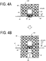
- a second composite 10A illustrated in FIG. 4A used in the electric circuit breaker device illustrated in FIG. 4B is the same as the cut composite 10 illustrated in FIG. 1A , except that the bottom clip 60 and the part corresponding to the cut composite 10 are integrally formed. However, the first connection portion 40 and the second connection portion 45 are attached with the same orientation as in the embodiment illustrated in FIG. 3 .
- the second composite 10A includes the projectile 30, the cut portion 20, the first connection portion 40, the second connection portion 45, and the bottom clip 60 all integrally formed together.
- the flat surface portion 21 of the cut portion 20 is in contact with the end surface 31 of the projectile 30, and the first through hole 22a of the first cut portion side surface portion 22 and the second through hole 23a of the second cut portion side surface portion 23 of the cut portion 20 are placed on, respectively, the first fixing pin 35 of the first side surface portion 32 and the second fixing pin 36 of the second side surface portion 33 of the projectile 30.
- a first attachment hole 43 of the first connection terminal 42 of the first connection portion 40 is placed on the first fixing pin 35 on which is placed the first through hole 22a of the cut portion 20, and the second attachment hole 48 of the second connection terminal 47 of the second connection portion 45 is placed on the second fixing pin 36 on which is placed the second through hole 23a of the cut portion 20.
- the end portion of the first fixing pin 35 on the opposite side from the connection portion of the first fixing pin 35 and the projectile 30 and the end portion of the second fixing pin 36 on the opposite side from the connection portion of the second fixing pin 36 and the projectile 30 are integrally formed with the inner wall surface of the recess portion 61 of the bottom clip 60.
- the first connection terminal 42 and the first cut portion side surface portion 22 of the cut portion 20 form two layers and are electrically connected.
- the second connection terminal 47 and the second cut portion side surface portion 23 of the cut portion 20 form two layers and are electrically connected.
- the conductor portion (the cut portion 20, the first connection portion 40, and the second connection portion 45) is disposed in a mold.
- the cut portion 20, the first connection portion 40, and the second connection portion 45 are aligned with the first through hole 22a of the cut portion 20 and the first attachment hole 43 of the first connection terminal 42 concentrically aligned and the second through hole 23a of the cut portion 20 and the second attachment hole 48 of the second connection terminal 47 concentrically aligned.
- the resin is injection molded and the second composite 10A illustrated in FIG. 4A is obtained.
- the second composite 10A of FIG. 4A is disposed in the mold, and the resin is injection molded to form the housing 51.
- the igniter 52 is inserted. In this way, the electric circuit breaker device 100 illustrated in FIG. 4B can be manufactured.
- a third composite 10B illustrated in FIG. 5A used in the electric circuit breaker device illustrated in FIG. 5B is the same as cut composite 10 illustrated in FIG. 1A , except that the housing 51 and the part corresponding to the cut composite 10 are integrally formed.
- the third composite 10B includes the projectile 30, the cut portion 20, the first connection portion 40, the second connection portion 45, and the housing 51 all integrally formed together.
- the flat surface portion 21 of the cut portion 20 is in contact with the end surface 31 of the projectile 30, and the first through hole 22a of the first cut portion side surface portion 22 and the second through hole 23a of the second cut portion side surface portion 23 of the cut portion 20 are placed on, respectively, the first fixing pin 35 of the first side surface portion 32 and the second fixing pin 36 of the second side surface portion 33 of the projectile 30.
- a first attachment hole 43 of the first connection terminal 42 of the first connection portion 40 is placed on the first fixing pin 35 on which is placed the first through hole 22a of the cut portion 20, and the second attachment hole 48 of the second connection terminal 47 of the second connection portion 45 is placed on the second fixing pin 36 on which is placed the second through hole 23a of the cut portion 20.
- the end portion of the first fixing pin 35 on the opposite side from the connection portion of the first fixing pin 35 and the projectile 30 and the end portion of the second fixing pin 36 on the opposite side from the connection portion of the second fixing pin 36 and the projectile 30 are integrally formed with the inner wall surface of the cylindrical space 55 of the housing 51.
- the first connection terminal 42 and the first cut portion side surface portion 22 of the cut portion 20 form two layers and are electrically connected.
- the second connection terminal 47 and the second cut portion side surface portion 23 of the cut portion 20 form two layers and are electrically connected.
- the housing 51 including the open ended cylindrical space 55 is disposed in a mold.
- the conductor portion (the first connection portion 40, the cut portion 20, and the second connection portion 45) is also disposed in the mold at the opening portion of the cylindrical space 55 of the housing 51 on the second end portion 50b side.
- the cut portion 20 includes a flat surface portion 21 with a quadrangular shape that includes a resin-injection hole that is a through hole (not illustrated), a first cut portion side surface portion 22 and a second cut portion side surface portion 23 extending down in the same direction from opposing edges of the flat surface portion 21 with a quadrangular shape, and a first through hole 22a and a second through hole 23a formed in the thickness direction of the first cut portion side surface portion 22 and the second cut portion side surface portion 23, respectively.
- the above-described resin-injection hole is not necessarily provided in the cut portion 20 used in the electric circuit breaker device 1 illustrated in FIGS. 1A to 1C , and a through hole may be provided instead.
- the first connection portion 40 and the second connection portion 45 are the same as those used in the electric circuit breaker device 1 illustrated in FIGS. 1A to 1C .
- the cut portion 20 and the first connection portion 40 are aligned with the first through hole 22a of the cut portion 20 and the first attachment hole 43 of the first connection terminal 42 concentrically aligned and the second through hole 23a of the cut portion 20 and the second attachment hole 48 of the second connection terminal 47 concentrically aligned.
- resin is injected from the resin-injection hole, i.e., through hole, of the cut portion 20 for injection molding, and the cut composite 10 is formed at the opening portion of the cylindrical space on the second end portion 50a side.
- the article (the third composite 10B) including the housing 51 and the cut composite 10 of FIG. 5A is placed in a mold, and resin is injection molded to form the bottom clip 60. In this way, an electric circuit breaker device 200 illustrated in FIG. 5B can be manufactured.
- the electric circuit breaker device of an embodiment of the present invention can be disposed in various types of electric circuits and is particularly suited to be used in an electric circuit including a battery (e.g., lithium ion battery) of a vehicle, an electric circuit of an electric vehicle, an electric circuit of an electric home appliance, a power station, a solar power generation device, a distribution board of various types of factories, and a stationary battery using an industrial battery such as an industrial lithium ion battery and an industrial lead storage battery.
- a battery e.g., lithium ion battery
Landscapes
- Engineering & Computer Science (AREA)
- Manufacturing & Machinery (AREA)
- Mechanical Engineering (AREA)
- Fuses (AREA)
- Connection Or Junction Boxes (AREA)
Claims (6)
- Dispositif disjoncteur électrique (1), comprenant :dans un boîtier (51) réalisé en résine synthétique comprenant un espace cylindrique (55) ouvert aux deux extrémités,un allumeur (52), un projectile en résine (30) et une partie conductrice qui forme une partie d'un circuit électrique disposés dans cet ordre à partir d'une première partie d'extrémité (50a) du côté de l'espace cylindrique (55) du boîtier (51) vers une deuxième partie d'extrémité axialement opposée (50b) du côté du boîtier (51) ; etune attache inférieure (60) réalisée en résine synthétique comprenant une partie évidée (61) qui forme un espace d'isolation (62) disposé sur un côté de la partie conductrice opposé à l'endroit où l'allumeur (52) et le projectile (30) sont disposés, l'espace d'isolation (62) étant formé par la partie évidée (61) de l'attache inférieure (60) fermant le boîtier (51) ; oùle projectile en résine (30) comprend une partie d'extrémité ayant une forme quadrangulaire, une première partie de surface latérale (32) et une deuxième partie de surface latérale (33) reliées à des bords opposés d'une surface d'extrémité (31) de la partie d'extrémité et une première broche de fixation (35) faisant saillie de la première partie de surface latérale (32) et une deuxième broche de fixation (36) faisant saillie de la deuxième partie de surface latérale (33) ;la première broche de fixation (35) comprend une première partie de cylindre (35a) située sur un côté de la première broche de fixation (35) plus proche de la première partie de surface latérale (32) et une première partie de diamètre augmenté d'extrémité (35b) située sur un côté de la première broche de fixation (35) plus proche d'une extrémité, un diamètre extérieur de la première partie de cylindre (35a) étant inférieur à un diamètre externe de la première partie de diamètre augmenté d'extrémité (35b) ;la deuxième broche de fixation (36) comprend une deuxième partie de cylindre (36a) située sur un côté de la deuxième broche de fixation (36) plus proche de la deuxième partie de surface latérale (33) et une deuxième partie de diamètre augmenté d'extrémité (36b) située sur un côté de la deuxième broche de fixation (36) plus proche d'une extrémité, un diamètre extérieur de la deuxième partie de cylindre (36a) étant inférieur à un diamètre externe de la deuxième partie de diamètre augmenté d'extrémité (36b) ;la partie conductrice est une partie de plaque comprenant une première partie de liaison (40) et une deuxième partie de liaison (45) sur des côtés opposés et une partie découpée (20) en tant que partie intermédiaire ;la partie découpée (20) comprend une partie de surface plate (21) ayant une forme quadrangulaire et une première partie de surface latérale de partie découpée (22) et une deuxième partie de surface latérale de partie découpée (23) s'étendant vers le bas dans une direction identique à partir de bords opposés de la partie de surface plate (21) ayant la forme quadrangulaire, la première partie de surface latérale de partie découpée (22) comprenant un premier trou traversant (22a) formé dans une direction d'épaisseur de la première partie de surface latérale de partie découpée (22) et la deuxième partie de surface latérale de partie découpée (23) comprenant un deuxième trou traversant (23a) formé dans une direction d'épaisseur de la deuxième partie de surface latérale de partie découpée (23) ;la première partie de liaison (40) comprend une première partie plate (41) ayant une forme rectangulaire dans une vue en plan et une première borne de liaison (42) s'étendant vers le bas depuis l'un des bords latéraux courts opposés de la première partie plate (41), la première borne de liaison (42) comprenant un premier trou de fixation (43) formé à travers la première borne de liaison (42) dans une direction d'épaisseur ;la deuxième partie de liaison (45) comprend une deuxième partie plate (46) ayant une forme rectangulaire dans une vue en plan et une deuxième borne de liaison (47) s'étendant vers le bas depuis l'un des bords latéraux courts opposés de la deuxième partie plate (46), la deuxième borne de liaison (47) comprenant un deuxième trou de fixation (48) formé à travers la deuxième borne de liaison (47) dans une direction d'épaisseur ;le projectile (30), la partie découpée (20), la première partie de liaison (40) et la deuxième partie de liaison (45) sont formés d'un seul tenant sous la forme d'un composite découpé (10) ;dans le composite découpé (10),la partie de surface plate (21) de la partie découpée (20) est en contact avec la surface d'extrémité du projectile (30),le premier trou traversant (22a) de la première partie de surface latérale de partie découpée (22) de la partie découpée (20) est placé sur la première partie de cylindre (35a) de la première broche de fixation (35) formée sur la première partie de surface latérale (32) du projectile (30), le premier trou de fixation (43) de la première borne de liaison (42) est également placé sur la première partie de cylindre (35a), une première surface (42a) du côté de la première borne de liaison (42) est en contact avec la première partie de surface latérale de partie découpée (22) et une deuxième surface (42b) du côté de la première borne de liaison (42) est en contact avec une surface intérieure de la première partie de diamètre augmenté d'extrémité (35b),le deuxième trou traversant (23a) de la deuxième partie de surface latérale de partie découpée (23) de la partie découpée (20) est placé sur la deuxième partie de cylindre (36a) de la deuxième broche de fixation (36) formée sur la deuxième partie de surface latérale (33) du projectile (30), le deuxième trou de fixation (48) de la deuxième borne de liaison (47) est également placé sur la deuxième partie de cylindre (36a), une première surface (47a) du côté de la deuxième borne de liaison (47) est en contact avec la deuxième partie de surface latérale de partie découpée (23) et une deuxième surface (47b) du côté de la deuxième borne de liaison (47) est en contact avec une surface intérieure de la deuxième partie de diamètre augmenté d'extrémité (36b) ; etla partie découpée (20) est orientée orthogonalement au boîtier (51) et disposée en face de l'espace d'isolation (62).
- Dispositif disjoncteur électrique (1), comprenant :dans un boîtier (51) réalisé en résine synthétique comprenant un espace cylindrique (55) ouvert aux deux extrémités,un allumeur (52), un projectile en résine (30) et une partie conductrice qui forme une partie d'un circuit électrique disposés dans cet ordre à partir d'une première partie d'extrémité (50a) du côté de l'espace cylindrique (55) du boîtier (51) vers une deuxième partie d'extrémité axialement opposée (50b) du côté du boîtier (51) ; etune attache inférieure (60) réalisée en résine synthétique comprenant une partie évidée (61) qui forme un espace d'isolation (62) disposé sur un côté de la partie conductrice opposé à l'endroit où l'allumeur (52) et le projectile (30) sont disposés, l'espace d'isolation (62) étant formé par la partie évidée (61) de l'attache inférieure (60) fermant le boîtier (51) ; oùle projectile en résine (30) comprend une partie d'extrémité ayant une forme quadrangulaire, une première partie de surface latérale (32) et une deuxième partie de surface latérale (33) reliées à des bords opposés d'une surface d'extrémité (31) de la partie d'extrémité et une première broche de fixation (35) faisant saillie de la première partie de surface latérale (32) et une deuxième broche de fixation (36) faisant saillie de la deuxième partie de surface latérale (33) ;la partie conductrice est une partie de plaque comprenant une première partie de liaison (40) et une deuxième partie de liaison (45) sur des côtés opposés et une partie découpée (20) en tant que partie intermédiaire ;la partie découpée (20) comprend une partie de surface plate (21) ayant une forme quadrangulaire et une première partie de surface latérale de partie découpée (22) et une deuxième partie de surface latérale de partie découpée (23) s'étendant vers le bas dans une direction identique à partir de bords opposés de la partie de surface plate (21) ayant la forme quadrangulaire, la première partie de surface latérale de partie découpée (22) comprenant un premier trou traversant (22a) formé dans une direction d'épaisseur de la première partie de surface latérale de partie découpée (22) et la deuxième partie de surface latérale de partie découpée (23) comprenant un deuxième trou traversant (23a) formé dans une direction d'épaisseur de la deuxième partie de surface latérale de partie découpée (23) ;la première partie de liaison (40) comprend une première partie plate (41) ayant une forme rectangulaire dans une vue en plan et une première borne de liaison (42) s'étendant vers le bas depuis l'un des bords latéraux courts opposés de la première partie plate (41), la première borne de liaison (42) comprenant un premier trou de fixation (43) formé à travers la première borne de liaison (42) dans une direction d'épaisseur ;la deuxième partie de liaison (45) comprend une deuxième partie plate (46) ayant une forme rectangulaire dans une vue en plan et une deuxième borne de liaison (47) s'étendant vers le bas depuis l'un des bords latéraux courts opposés de la deuxième partie plate (46), la deuxième borne de liaison (47) comprenant un deuxième trou de fixation (48) formé à travers la deuxième borne de liaison (47) dans une direction d'épaisseur ;le projectile (30), la partie découpée (20), la première partie de liaison (40) la deuxième partie de liaison (45) et l'attache inférieure (60) sont formés d'un seul tenant sous la forme d'un deuxième composite (10A) ;dans le deuxième composite (10A),la partie de surface plate (21) de la partie découpée (20) est en contact avec la surface d'extrémité du projectile (30),le premier trou traversant (22a) de la première partie de surface latérale de partie découpée (22) de la partie découpée (20) est placé sur la première broche de fixation (35) formée sur la première partie de surface latérale (32) du projectile (30), le premier trou de fixation (43) de la première borne de liaison (42) est également placé sur la première broche de fixation (35) et une première surface (42a) du côté de la première borne de liaison (42) est en contact avec la première partie de surface latérale de partie découpée (22),le deuxième trou traversant (23a) de la deuxième partie de surface latérale de partie découpée (23) de la partie découpée (20) est placé sur la deuxième broche de fixation (36) formée sur la deuxième partie de surface latérale (33) du projectile (30), le deuxième trou de fixation (48) de la deuxième borne de liaison (47) est également placé sur la deuxième broche de fixation (36), une deuxième surface (47a) du côté de la deuxième borne de liaison (47) est en contact avec la deuxième partie de surface latérale de partie découpée (23), etune partie d'extrémité de la première broche de fixation (35) sur un côté opposé de l'endroit où le projectile (30) est situé et une partie d'extrémité de la deuxième broche de fixation (36) sur un côté opposé de l'endroit où le projectile (30) est situé sont formées d'un seul tenant avec une surface de paroi intérieure de la partie évidée (61) de l'attache inférieure (60) ; etla partie découpée (20) est orientée orthogonalement au boîtier (51) et disposée en face de l'espace d'isolation (62).
- Dispositif disjoncteur électrique (200), comprenant :dans un boîtier (51) réalisé en résine synthétique comprenant un espace cylindrique (55) ouvert aux deux extrémités,un allumeur (52), un projectile en résine (30) et une partie conductrice qui forme une partie d'un circuit électrique disposés dans cet ordre à partir d'une première partie d'extrémité (50a) du côté de l'espace cylindrique (55) du boîtier (51) vers une deuxième partie d'extrémité axialement opposée (50b) du côté du boîtier (51) ; etune attache inférieure (60) réalisée en résine synthétique comprenant une partie évidée (61) qui forme un espace d'isolation (62) disposé sur un côté de la partie conductrice opposé à l'endroit où l'allumeur (52) et le projectile (30) sont disposés, l'espace d'isolation (62) étant formé par la partie évidée (61) de l'attache inférieure (60) fermant le boîtier (51) ; oùle projectile en résine (30) comprend une partie d'extrémité ayant une forme quadrangulaire, une première partie de surface latérale (32) et une deuxième partie de surface latérale (33) reliées à des bords opposés d'une surface d'extrémité (31) de la partie d'extrémité et une première broche de fixation (35) faisant saillie de la première partie de surface latérale (32) et une deuxième broche de fixation (36) faisant saillie de la deuxième partie de surface latérale (33) ;la partie conductrice est une partie de plaque comprenant une première partie de liaison (40) et une deuxième partie de liaison (45) sur des côtés opposés et une partie découpée (20) en tant que partie intermédiaire ;la partie découpée (20) comprend une partie de surface plate (21) ayant une forme quadrangulaire et une première partie de surface latérale de partie découpée (22) et une deuxième partie de surface latérale de partie découpée (23) s'étendant vers le bas dans une direction identique à partir de bords opposés de la partie de surface plate (21) ayant la forme quadrangulaire, la première partie de surface latérale de partie découpée (22) comprenant un premier trou traversant (22a) formé dans une direction d'épaisseur de la première partie de surface latérale de partie découpée (22) et la deuxième partie de surface latérale de partie découpée (23) comprenant un deuxième trou traversant (23a) formé dans une direction d'épaisseur de la deuxième partie de surface latérale de partie découpée (23) ;la première partie de liaison (40) comprend une première partie plate (41) ayant une forme rectangulaire dans une vue en plan et une première borne de liaison (42) s'étendant vers le bas depuis l'un des bords latéraux courts opposés de la première partie plate (41), la première borne de liaison (42) comprenant un premier trou de fixation (43) formé à travers la première borne de liaison (42) dans une direction d'épaisseur ;la deuxième partie de liaison (45) comprend une deuxième partie plate (46) ayant une forme rectangulaire dans une vue en plan et une deuxième borne de liaison (47) s'étendant vers le bas depuis l'un des bords latéraux courts opposés de la deuxième partie plate (46), la deuxième borne de liaison (47) comprenant un deuxième trou de fixation (48) formé à travers la deuxième borne de liaison (47) dans une direction d'épaisseur ;le projectile (30), la partie découpée (20), la première partie de liaison (40) et la deuxième partie de liaison (45) sont formés d'un seul tenant sous la forme d'un troisième composite (10B) ;dans le troisième composite (10B),la partie de surface plate (21) de la partie découpée (20) est en contact avec la surface d'extrémité du projectile (30),le premier trou traversant (22a) de la première partie de surface latérale de partie découpée (22) de la partie découpée (20) est placé sur une première broche de fixation (35) formée sur la première partie de surface latérale (32) du projectile (30), le premier trou de fixation (43) de la première borne de liaison (42) est également placé sur la première broche de fixation (35), une première surface (42a) du côté de la première borne de liaison (42) est en contact avec la première partie de surface latérale de partie découpée (22),le deuxième trou traversant (23a) de la deuxième partie de surface latérale de partie découpée (23) de la partie découpée (20) est placé sur la deuxième broche de fixation (36) formée sur une deuxième partie de surface latérale (33) du projectile (30), le deuxième trou de fixation (48) de la deuxième borne de liaison (47) est également placé sur la deuxième broche de fixation (36), une deuxième surface (47a) du côté de la deuxième borne de liaison (47) est en contact avec la deuxième partie de surface latérale de partie découpée (23), etune partie d'extrémité de la première broche de fixation (35) sur un côté opposé de l'endroit où le projectile (30) est situé et une partie d'extrémité de la deuxième broche de fixation (36) sur un côté opposé de l'endroit où le projectile (30) est situé sont formées d'un seul tenant avec une surface de paroi intérieure de l'espace cylindrique (55) du boîtier (51) ; etla partie découpée (20) est orientée orthogonalement au boîtier (51) et disposée en face de l'espace d'isolation (62).
- Procédé de fabrication du composite découpé (10) selon la revendication 1 comprenant le projectile (30), la partie découpée (20), la première partie de liaison (40) et la deuxième partie de liaison (45) formés ensemble d'un seul tenant, le procédé comprenant :1) la disposition d'une partie découpée (20) dans un moule, la partie découpée (20) comprenant une partie de surface plate (21) ayant une forme quadrangulaire et une première partie de surface latérale de partie découpée (22) et une deuxième partie de surface latérale de partie découpée (23) qui sont des parties de surface latérales s'étendant vers le bas dans une direction identique à partir de bords opposés de la partie de surface plate (21) ayant la forme quadrangulaire, la première partie de surface latérale de partie découpée (22) comprenant un premier trou traversant (22a) formé dans une direction d'épaisseur de la première partie de surface latérale de partie découpée (22) et la deuxième partie de surface latérale de partie découpée (23) comprenant un deuxième trou traversant (22a) formé dans une direction d'épaisseur de la deuxième partie de surface latérale de partie découpée (23) ;2) la formation d'un seul tenant par moulage par injection d'une résine pour former un projectile (30) et par moulage d'un seul tenant du projectile (30) et de la partie découpée (20) ensemble, une partie de surface plate (21) de la partie découpée (20) étant en contact avec une surface d'extrémité du projectile (30), un premier trou traversant (22a) d'une première partie de surface latérale de partie découpée (22) de la partie découpée (20) étant placé sur une première broche de fixation (35) formée sur une première partie de surface latérale (32) du projectile (30) et un deuxième trou traversant (23a) d'une deuxième partie de surface latérale de partie découpée (23) de la partie découpée (20) étant placé sur une deuxième broche de fixation (36) formée sur une deuxième partie de surface latérale (33) du projectile (30) ; et3) la formation d'un seul tenant du projectile (30), de la partie découpée (20), de la première partie de liaison (40) et de la deuxième partie de liaison (45) et l'obtention d'un composite découpé (10) en plaçant un premier trou de fixation (43) de la première partie de liaison (40) sur la première broche de fixation (35) et en plaçant un deuxième trou de fixation (48) de la deuxième partie de liaison (45) sur la deuxième broche de fixation (36), puis en déformant la première broche de fixation (35) et la deuxième broche de fixation (36).
- Procédé de fabrication du deuxième composite (10A) selon la revendication 2 comprenant le projectile (30), la partie découpée (20), la première partie de liaison (40), la deuxième partie de liaison (45) et l'attache inférieure (60) formés ensemble d'un seul tenant, le procédé comprenant :1) la disposition d'une partie découpée (20), d'une première partie de liaison (40) et d'une deuxième partie de liaison (45) dans un moule, la partie découpée (20) comprenant une partie de surface plate (21) ayant une forme quadrangulaire et une première partie de surface latérale de partie découpée (22) et une deuxième partie de surface latérale de partie découpée (23) qui sont des parties de surface latérales s'étendant vers le bas dans une direction identique à partir de bords opposés de la partie de surface plate (21) ayant la forme quadrangulaire, la première partie de surface latérale de partie découpée (22) comprenant un premier trou traversant (22a) formé dans une direction d'épaisseur de la première partie de surface latérale de partie découpée (22) et la deuxième partie de surface latérale de partie découpée (23) comprenant un deuxième trou traversant (23a) formé dans une direction d'épaisseur de la deuxième partie de surface latérale de partie découpée (23), la première partie de liaison (40) comprenant une première partie plate (41) ayant une forme rectangulaire dans une vue en plan et une première borne de liaison (42) s'étendant vers le bas depuis l'un des bords latéraux courts opposés de la première partie plate (41), la première borne de liaison (42) comprenant un premier trou de fixation (43) formé à travers la première borne de liaison (42) dans une direction d'épaisseur et la deuxième partie de liaison (45) comprenant une deuxième partie plate (46) ayant une forme rectangulaire dans une vue en plan et une deuxième borne de liaison (47) s'étendant vers le bas depuis l'un des bords latéraux courts opposés de la deuxième partie plate (46), la deuxième borne de liaison (47) comprenant un deuxième trou de fixation (48) formé à travers la deuxième borne de liaison (47) dans une direction d'épaisseur, d'une manière telle que le premier trou traversant (22a) de la partie découpée (20) et le premier trou de fixation (43) de la première partie de liaison (40) soient alignés de manière concentrique l'un par rapport à l'autre et que le deuxième trou traversant (23a) de la partie découpée (20) et le deuxième trou de fixation (48) de la deuxième borne de liaison (47) soient alignés de manière concentrique l'un par rapport à l'autre ; et2) l'obtention d'un deuxième composite (10A) par moulage par injection d'une résine.
- Procédé de fabrication du troisième composite (10B) selon la revendication 3 comprenant le projectile (30), la partie découpée (20), la première partie de liaison (40), la deuxième partie de liaison (45) et la surface de paroi intérieure de l'espace cylindrique (55) du boîtier (51) formés ensemble d'un seul tenant, le procédé comprenant :1) la disposition d'un boîtier (51) comprenant un espace cylindrique à extrémités ouvertes (55) dans un moule ;2) la disposition d'une première partie de liaison (40), d'une partie découpée (20) et d'une deuxième partie de liaison (45) dans le moule au niveau d'une partie d'ouverture d'un espace cylindrique (55) du boîtier (51) sur un côté d'une deuxième partie d'extrémité (50b), la partie découpée (20) comprenant une partie de surface plate (21) ayant une forme quadrangulaire comprenant un trou traversant qui forme un trou d'injection de résine et une première partie de surface latérale de partie découpée (22) et une deuxième partie de surface latérale de partie découpée (23) qui sont des parties de surface latérales s'étendant vers le bas dans une direction identique à partir de bords opposés de la partie de surface plate (21) ayant la forme quadrangulaire, la première partie de surface latérale de partie découpée (22) comprenant un premier trou traversant (22a) formé dans une direction d'épaisseur de la première partie de surface latérale de partie découpée (22) et la deuxième partie de surface latérale de partie découpée (23) comprenant un deuxième trou traversant (23a) formé dans une direction d'épaisseur de la deuxième partie de surface latérale de partie découpée (23), la première partie de liaison (40) comprenant une première partie plate (41) ayant une forme rectangulaire dans une vue en plan et une première borne de liaison (42) s'étendant vers le bas depuis l'un des bords latéraux courts opposés de la première partie plate (41), la première borne de liaison (42) comprenant un premier trou de fixation (43) formé à travers la première borne de liaison (42) dans une direction d'épaisseur et la deuxième partie de liaison (45) comprenant une deuxième partie plate (46) ayant une forme rectangulaire dans une vue en plan et une deuxième borne de liaison (47) s'étendant vers le bas depuis l'un des bords latéraux courts opposés de la deuxième partie plate (46), la deuxième borne de liaison (47) comprenant un deuxième trou de fixation (48) formé à travers la deuxième borne de liaison (47) dans une direction d'épaisseur, de manière à ce que le premier trou traversant (22a) de la partie découpée (20) et le premier trou de fixation (43) de la première partie de liaison (40) soient alignés de manière concentrique l'un par rapport à l'autre et que le deuxième trou traversant (23a) de la partie découpée (20) et le deuxième trou de fixation (48) de la deuxième borne de liaison (47) soient alignés de manière concentrique l'un par rapport à l'autre ; et3) la formation d'un composite découpé (10B) au niveau de la partie d'ouverture de l'espace cylindrique (55) du côté de la deuxième partie d'extrémité (50b) par moulage par injection d'une résine injectée depuis le trou traversant qui forme un trou d'injection de résine de la partie découpée (20).
Applications Claiming Priority (2)
| Application Number | Priority Date | Filing Date | Title |
|---|---|---|---|
| JP2017157846A JP6889065B2 (ja) | 2017-08-18 | 2017-08-18 | 発射体の組立体と電気回路遮断装置 |
| PCT/JP2018/030181 WO2019035440A1 (fr) | 2017-08-18 | 2018-08-13 | Ensemble projectile et dispositif d'interruption de circuit électrique |
Publications (3)
| Publication Number | Publication Date |
|---|---|
| EP3671796A1 EP3671796A1 (fr) | 2020-06-24 |
| EP3671796A4 EP3671796A4 (fr) | 2021-05-12 |
| EP3671796B1 true EP3671796B1 (fr) | 2022-04-27 |
Family
ID=65362504
Family Applications (1)
| Application Number | Title | Priority Date | Filing Date |
|---|---|---|---|
| EP18846279.0A Active EP3671796B1 (fr) | 2017-08-18 | 2018-08-13 | Ensemble projectile et dispositif d'interruption de circuit électrique |
Country Status (6)
| Country | Link |
|---|---|
| US (1) | US10910181B2 (fr) |
| EP (1) | EP3671796B1 (fr) |
| JP (1) | JP6889065B2 (fr) |
| KR (1) | KR102479202B1 (fr) |
| CN (1) | CN110914948B (fr) |
| WO (1) | WO2019035440A1 (fr) |
Families Citing this family (2)
| Publication number | Priority date | Publication date | Assignee | Title |
|---|---|---|---|---|
| CN114178849B (zh) * | 2021-12-31 | 2022-11-22 | 成都中科卓尔智能科技集团有限公司 | 一种底火压装生产系统 |
| AT525557B1 (de) * | 2022-01-25 | 2023-05-15 | Astotec Automotive Gmbh | Verfahren zur Herstellung eines Leiters für einen Stromtrenner, Leiter für einen Stromtrenner sowie Stromtrenner |
Family Cites Families (21)
| Publication number | Priority date | Publication date | Assignee | Title |
|---|---|---|---|---|
| US4224487A (en) * | 1978-02-23 | 1980-09-23 | Simonsen Bent P | Fast acting explosive circuit interrupter |
| JP2555202B2 (ja) * | 1989-09-29 | 1996-11-20 | 工業技術院長 | 高速大電流スイッチ |
| US6295930B1 (en) * | 1998-01-08 | 2001-10-02 | Harness System Technologies Research, Ltd. | Circuit breaker |
| JPH11232979A (ja) | 1998-02-17 | 1999-08-27 | Harness Syst Tech Res Ltd | 回路遮断装置 |
| US6222439B1 (en) | 1998-02-17 | 2001-04-24 | Sumitomo Wiring Systems, Ltd. | Circuit breaking device |
| DE19817133A1 (de) * | 1998-04-19 | 1999-10-28 | Lell Peter | Powerswitch |
| EP1492139B1 (fr) * | 2003-06-26 | 2016-01-06 | Autoliv Development AB | Ciseau pour element de séparation pyromecanique |
| EP1502683B1 (fr) * | 2003-07-29 | 2007-09-19 | Delphi Technologies, Inc. | Dispositif de découpe de matériaux massifs et compacts à entraînement pyrotechnique |
| US7123124B2 (en) | 2003-10-17 | 2006-10-17 | Special Devices, Inc. | Pyrotechnic circuit breaker |
| US7239225B2 (en) | 2003-10-17 | 2007-07-03 | Special Devices, Inc. | Pyrotechnic circuit breaker |
| FR2953324B1 (fr) * | 2009-11-27 | 2012-06-08 | Snpe Materiaux Energetiques | Interrupteur electrique a tiroir coulissant formant coupe-circuit ou commutateur |
| JP4985871B1 (ja) * | 2010-12-27 | 2012-07-25 | ダイキン工業株式会社 | 切断装置 |
| JP4973779B1 (ja) * | 2010-12-27 | 2012-07-11 | ダイキン工業株式会社 | 切断装置 |
| JP5545231B2 (ja) * | 2011-01-28 | 2014-07-09 | 豊田合成株式会社 | 導通遮断装置 |
| US20120234162A1 (en) | 2011-03-15 | 2012-09-20 | Special Devices, Inc. | Pyrotechnic actuator and method of actuating a pyrotechnic actuator |
| JP5874583B2 (ja) * | 2012-08-29 | 2016-03-02 | 豊田合成株式会社 | 導通遮断装置 |
| JP2014049300A (ja) | 2012-08-31 | 2014-03-17 | Toyoda Gosei Co Ltd | 導通遮断装置 |
| CN103247498A (zh) * | 2013-03-29 | 2013-08-14 | 厦门赛尔特电子有限公司 | 一种带双爪簧片的温度保险丝 |
| JP2015223962A (ja) * | 2014-05-28 | 2015-12-14 | 株式会社ダイセル | ガス発生器 |
| JP6414816B2 (ja) * | 2014-10-29 | 2018-10-31 | 株式会社ダイセル | 電気回路遮断装置 |
| JP6536378B2 (ja) * | 2015-11-24 | 2019-07-03 | 日立金属株式会社 | コネクタ及びその製造方法ならびにワイヤハーネス |
-
2017
- 2017-08-18 JP JP2017157846A patent/JP6889065B2/ja active Active
-
2018
- 2018-08-13 KR KR1020207004228A patent/KR102479202B1/ko active Active
- 2018-08-13 US US16/638,874 patent/US10910181B2/en active Active
- 2018-08-13 EP EP18846279.0A patent/EP3671796B1/fr active Active
- 2018-08-13 WO PCT/JP2018/030181 patent/WO2019035440A1/fr not_active Ceased
- 2018-08-13 CN CN201880047503.0A patent/CN110914948B/zh active Active
Also Published As
| Publication number | Publication date |
|---|---|
| CN110914948A (zh) | 2020-03-24 |
| US20200194203A1 (en) | 2020-06-18 |
| KR20200038476A (ko) | 2020-04-13 |
| CN110914948B (zh) | 2022-06-17 |
| EP3671796A4 (fr) | 2021-05-12 |
| EP3671796A1 (fr) | 2020-06-24 |
| JP6889065B2 (ja) | 2021-06-18 |
| WO2019035440A1 (fr) | 2019-02-21 |
| JP2019036480A (ja) | 2019-03-07 |
| US10910181B2 (en) | 2021-02-02 |
| KR102479202B1 (ko) | 2022-12-20 |
Similar Documents
| Publication | Publication Date | Title |
|---|---|---|
| CN102834889B (zh) | 车辆电力线路保险装置 | |
| CN113490829B (zh) | 发射体的组装体和电路切断装置 | |
| US10475610B2 (en) | Electric circuit breaker device | |
| US11004635B2 (en) | Electric circuit breaker device | |
| US8622765B2 (en) | Cable connecting device | |
| CN109416999B (zh) | 电路切断装置 | |
| US6046665A (en) | Fusible link, and link and cable assembly | |
| US7767921B2 (en) | Circuit breaker for electrical power leads of motor vehicles | |
| US11929222B2 (en) | Pyrotechnic device with riveted housing | |
| US10910181B2 (en) | Projectile assembly and electric circuit breaker device | |
| US12444561B2 (en) | Electric circuit breaker device that extinguishes an arc generated when conductor portion is cut | |
| US20170176223A1 (en) | Sensor Unit for a Vehicle | |
| WO2015096018A1 (fr) | Capteur de vitesse modulaire | |
| US11764013B2 (en) | Electrical disconnecting device, system comprising a disconnecting device, and method for producing a disconnecting device | |
| US20020130755A1 (en) | Protector device | |
| JP2017220386A (ja) | 感温ペレット型温度ヒューズ | |
| JP4859781B2 (ja) | 端子、端子台及び端子台の製造方法 | |
| KR101725759B1 (ko) | 저항 발열형 온도퓨즈 조립체 | |
| KR200398542Y1 (ko) | 보안장치 내장용 콘덴서 | |
| CN107255263B (zh) | 车灯中的线路板、插片和组合后盖的连接结构及连接方法 |
Legal Events
| Date | Code | Title | Description |
|---|---|---|---|
| STAA | Information on the status of an ep patent application or granted ep patent |
Free format text: STATUS: THE INTERNATIONAL PUBLICATION HAS BEEN MADE |
|
| PUAI | Public reference made under article 153(3) epc to a published international application that has entered the european phase |
Free format text: ORIGINAL CODE: 0009012 |
|
| STAA | Information on the status of an ep patent application or granted ep patent |
Free format text: STATUS: REQUEST FOR EXAMINATION WAS MADE |
|
| 17P | Request for examination filed |
Effective date: 20200214 |
|
| AK | Designated contracting states |
Kind code of ref document: A1 Designated state(s): AL AT BE BG CH CY CZ DE DK EE ES FI FR GB GR HR HU IE IS IT LI LT LU LV MC MK MT NL NO PL PT RO RS SE SI SK SM TR |
|
| AX | Request for extension of the european patent |
Extension state: BA ME |
|
| DAV | Request for validation of the european patent (deleted) | ||
| DAX | Request for extension of the european patent (deleted) | ||
| A4 | Supplementary search report drawn up and despatched |
Effective date: 20210412 |
|
| RIC1 | Information provided on ipc code assigned before grant |
Ipc: H01H 39/00 20060101AFI20210406BHEP |
|
| GRAP | Despatch of communication of intention to grant a patent |
Free format text: ORIGINAL CODE: EPIDOSNIGR1 |
|
| STAA | Information on the status of an ep patent application or granted ep patent |
Free format text: STATUS: GRANT OF PATENT IS INTENDED |
|
| GRAJ | Information related to disapproval of communication of intention to grant by the applicant or resumption of examination proceedings by the epo deleted |
Free format text: ORIGINAL CODE: EPIDOSDIGR1 |
|
| GRAP | Despatch of communication of intention to grant a patent |
Free format text: ORIGINAL CODE: EPIDOSNIGR1 |
|
| INTG | Intention to grant announced |
Effective date: 20211012 |
|
| INTG | Intention to grant announced |
Effective date: 20211027 |
|
| GRAJ | Information related to disapproval of communication of intention to grant by the applicant or resumption of examination proceedings by the epo deleted |
Free format text: ORIGINAL CODE: EPIDOSDIGR1 |
|
| STAA | Information on the status of an ep patent application or granted ep patent |
Free format text: STATUS: REQUEST FOR EXAMINATION WAS MADE |
|
| GRAP | Despatch of communication of intention to grant a patent |
Free format text: ORIGINAL CODE: EPIDOSNIGR1 |
|
| STAA | Information on the status of an ep patent application or granted ep patent |
Free format text: STATUS: GRANT OF PATENT IS INTENDED |
|
| INTC | Intention to grant announced (deleted) | ||
| GRAS | Grant fee paid |
Free format text: ORIGINAL CODE: EPIDOSNIGR3 |
|
| GRAA | (expected) grant |
Free format text: ORIGINAL CODE: 0009210 |
|
| STAA | Information on the status of an ep patent application or granted ep patent |
Free format text: STATUS: THE PATENT HAS BEEN GRANTED |
|
| INTG | Intention to grant announced |
Effective date: 20220310 |
|
| AK | Designated contracting states |
Kind code of ref document: B1 Designated state(s): AL AT BE BG CH CY CZ DE DK EE ES FI FR GB GR HR HU IE IS IT LI LT LU LV MC MK MT NL NO PL PT RO RS SE SI SK SM TR |
|
| REG | Reference to a national code |
Ref country code: GB Ref legal event code: FG4D |
|
| REG | Reference to a national code |
Ref country code: CH Ref legal event code: EP |
|
| REG | Reference to a national code |
Ref country code: AT Ref legal event code: REF Ref document number: 1487604 Country of ref document: AT Kind code of ref document: T Effective date: 20220515 |
|
| REG | Reference to a national code |
Ref country code: DE Ref legal event code: R096 Ref document number: 602018034658 Country of ref document: DE |
|
| REG | Reference to a national code |
Ref country code: IE Ref legal event code: FG4D |
|
| REG | Reference to a national code |
Ref country code: LT Ref legal event code: MG9D |
|
| REG | Reference to a national code |
Ref country code: NL Ref legal event code: MP Effective date: 20220427 |
|
| REG | Reference to a national code |
Ref country code: AT Ref legal event code: MK05 Ref document number: 1487604 Country of ref document: AT Kind code of ref document: T Effective date: 20220427 |
|
| PG25 | Lapsed in a contracting state [announced via postgrant information from national office to epo] |
Ref country code: NL Free format text: LAPSE BECAUSE OF FAILURE TO SUBMIT A TRANSLATION OF THE DESCRIPTION OR TO PAY THE FEE WITHIN THE PRESCRIBED TIME-LIMIT Effective date: 20220427 |
|
| PG25 | Lapsed in a contracting state [announced via postgrant information from national office to epo] |
Ref country code: SE Free format text: LAPSE BECAUSE OF FAILURE TO SUBMIT A TRANSLATION OF THE DESCRIPTION OR TO PAY THE FEE WITHIN THE PRESCRIBED TIME-LIMIT Effective date: 20220427 Ref country code: PT Free format text: LAPSE BECAUSE OF FAILURE TO SUBMIT A TRANSLATION OF THE DESCRIPTION OR TO PAY THE FEE WITHIN THE PRESCRIBED TIME-LIMIT Effective date: 20220829 Ref country code: NO Free format text: LAPSE BECAUSE OF FAILURE TO SUBMIT A TRANSLATION OF THE DESCRIPTION OR TO PAY THE FEE WITHIN THE PRESCRIBED TIME-LIMIT Effective date: 20220727 Ref country code: LT Free format text: LAPSE BECAUSE OF FAILURE TO SUBMIT A TRANSLATION OF THE DESCRIPTION OR TO PAY THE FEE WITHIN THE PRESCRIBED TIME-LIMIT Effective date: 20220427 Ref country code: HR Free format text: LAPSE BECAUSE OF FAILURE TO SUBMIT A TRANSLATION OF THE DESCRIPTION OR TO PAY THE FEE WITHIN THE PRESCRIBED TIME-LIMIT Effective date: 20220427 Ref country code: GR Free format text: LAPSE BECAUSE OF FAILURE TO SUBMIT A TRANSLATION OF THE DESCRIPTION OR TO PAY THE FEE WITHIN THE PRESCRIBED TIME-LIMIT Effective date: 20220728 Ref country code: FI Free format text: LAPSE BECAUSE OF FAILURE TO SUBMIT A TRANSLATION OF THE DESCRIPTION OR TO PAY THE FEE WITHIN THE PRESCRIBED TIME-LIMIT Effective date: 20220427 Ref country code: ES Free format text: LAPSE BECAUSE OF FAILURE TO SUBMIT A TRANSLATION OF THE DESCRIPTION OR TO PAY THE FEE WITHIN THE PRESCRIBED TIME-LIMIT Effective date: 20220427 Ref country code: BG Free format text: LAPSE BECAUSE OF FAILURE TO SUBMIT A TRANSLATION OF THE DESCRIPTION OR TO PAY THE FEE WITHIN THE PRESCRIBED TIME-LIMIT Effective date: 20220727 Ref country code: AT Free format text: LAPSE BECAUSE OF FAILURE TO SUBMIT A TRANSLATION OF THE DESCRIPTION OR TO PAY THE FEE WITHIN THE PRESCRIBED TIME-LIMIT Effective date: 20220427 |
|
| PG25 | Lapsed in a contracting state [announced via postgrant information from national office to epo] |
Ref country code: RS Free format text: LAPSE BECAUSE OF FAILURE TO SUBMIT A TRANSLATION OF THE DESCRIPTION OR TO PAY THE FEE WITHIN THE PRESCRIBED TIME-LIMIT Effective date: 20220427 Ref country code: PL Free format text: LAPSE BECAUSE OF FAILURE TO SUBMIT A TRANSLATION OF THE DESCRIPTION OR TO PAY THE FEE WITHIN THE PRESCRIBED TIME-LIMIT Effective date: 20220427 Ref country code: LV Free format text: LAPSE BECAUSE OF FAILURE TO SUBMIT A TRANSLATION OF THE DESCRIPTION OR TO PAY THE FEE WITHIN THE PRESCRIBED TIME-LIMIT Effective date: 20220427 Ref country code: IS Free format text: LAPSE BECAUSE OF FAILURE TO SUBMIT A TRANSLATION OF THE DESCRIPTION OR TO PAY THE FEE WITHIN THE PRESCRIBED TIME-LIMIT Effective date: 20220827 |
|
| REG | Reference to a national code |
Ref country code: DE Ref legal event code: R097 Ref document number: 602018034658 Country of ref document: DE |
|
| PG25 | Lapsed in a contracting state [announced via postgrant information from national office to epo] |
Ref country code: SM Free format text: LAPSE BECAUSE OF FAILURE TO SUBMIT A TRANSLATION OF THE DESCRIPTION OR TO PAY THE FEE WITHIN THE PRESCRIBED TIME-LIMIT Effective date: 20220427 Ref country code: SK Free format text: LAPSE BECAUSE OF FAILURE TO SUBMIT A TRANSLATION OF THE DESCRIPTION OR TO PAY THE FEE WITHIN THE PRESCRIBED TIME-LIMIT Effective date: 20220427 Ref country code: RO Free format text: LAPSE BECAUSE OF FAILURE TO SUBMIT A TRANSLATION OF THE DESCRIPTION OR TO PAY THE FEE WITHIN THE PRESCRIBED TIME-LIMIT Effective date: 20220427 Ref country code: EE Free format text: LAPSE BECAUSE OF FAILURE TO SUBMIT A TRANSLATION OF THE DESCRIPTION OR TO PAY THE FEE WITHIN THE PRESCRIBED TIME-LIMIT Effective date: 20220427 Ref country code: DK Free format text: LAPSE BECAUSE OF FAILURE TO SUBMIT A TRANSLATION OF THE DESCRIPTION OR TO PAY THE FEE WITHIN THE PRESCRIBED TIME-LIMIT Effective date: 20220427 Ref country code: CZ Free format text: LAPSE BECAUSE OF FAILURE TO SUBMIT A TRANSLATION OF THE DESCRIPTION OR TO PAY THE FEE WITHIN THE PRESCRIBED TIME-LIMIT Effective date: 20220427 |
|
| PLBE | No opposition filed within time limit |
Free format text: ORIGINAL CODE: 0009261 |
|
| STAA | Information on the status of an ep patent application or granted ep patent |
Free format text: STATUS: NO OPPOSITION FILED WITHIN TIME LIMIT |
|
| PG25 | Lapsed in a contracting state [announced via postgrant information from national office to epo] |
Ref country code: MC Free format text: LAPSE BECAUSE OF FAILURE TO SUBMIT A TRANSLATION OF THE DESCRIPTION OR TO PAY THE FEE WITHIN THE PRESCRIBED TIME-LIMIT Effective date: 20220427 Ref country code: AL Free format text: LAPSE BECAUSE OF FAILURE TO SUBMIT A TRANSLATION OF THE DESCRIPTION OR TO PAY THE FEE WITHIN THE PRESCRIBED TIME-LIMIT Effective date: 20220427 |
|
| REG | Reference to a national code |
Ref country code: CH Ref legal event code: PL |
|
| 26N | No opposition filed |
Effective date: 20230130 |
|
| GBPC | Gb: european patent ceased through non-payment of renewal fee |
Effective date: 20220813 |
|
| PG25 | Lapsed in a contracting state [announced via postgrant information from national office to epo] |
Ref country code: LU Free format text: LAPSE BECAUSE OF NON-PAYMENT OF DUE FEES Effective date: 20220813 Ref country code: LI Free format text: LAPSE BECAUSE OF NON-PAYMENT OF DUE FEES Effective date: 20220831 Ref country code: CH Free format text: LAPSE BECAUSE OF NON-PAYMENT OF DUE FEES Effective date: 20220831 |
|
| REG | Reference to a national code |
Ref country code: BE Ref legal event code: MM Effective date: 20220831 |
|
| PG25 | Lapsed in a contracting state [announced via postgrant information from national office to epo] |
Ref country code: SI Free format text: LAPSE BECAUSE OF FAILURE TO SUBMIT A TRANSLATION OF THE DESCRIPTION OR TO PAY THE FEE WITHIN THE PRESCRIBED TIME-LIMIT Effective date: 20220427 |
|
| PG25 | Lapsed in a contracting state [announced via postgrant information from national office to epo] |
Ref country code: IE Free format text: LAPSE BECAUSE OF NON-PAYMENT OF DUE FEES Effective date: 20220813 Ref country code: FR Free format text: LAPSE BECAUSE OF NON-PAYMENT OF DUE FEES Effective date: 20220831 |
|
| PG25 | Lapsed in a contracting state [announced via postgrant information from national office to epo] |
Ref country code: BE Free format text: LAPSE BECAUSE OF NON-PAYMENT OF DUE FEES Effective date: 20220831 |
|
| PG25 | Lapsed in a contracting state [announced via postgrant information from national office to epo] |
Ref country code: GB Free format text: LAPSE BECAUSE OF NON-PAYMENT OF DUE FEES Effective date: 20220813 |
|
| PG25 | Lapsed in a contracting state [announced via postgrant information from national office to epo] |
Ref country code: IT Free format text: LAPSE BECAUSE OF FAILURE TO SUBMIT A TRANSLATION OF THE DESCRIPTION OR TO PAY THE FEE WITHIN THE PRESCRIBED TIME-LIMIT Effective date: 20220427 |
|
| PG25 | Lapsed in a contracting state [announced via postgrant information from national office to epo] |
Ref country code: CY Free format text: LAPSE BECAUSE OF FAILURE TO SUBMIT A TRANSLATION OF THE DESCRIPTION OR TO PAY THE FEE WITHIN THE PRESCRIBED TIME-LIMIT Effective date: 20220427 |
|
| PG25 | Lapsed in a contracting state [announced via postgrant information from national office to epo] |
Ref country code: MK Free format text: LAPSE BECAUSE OF FAILURE TO SUBMIT A TRANSLATION OF THE DESCRIPTION OR TO PAY THE FEE WITHIN THE PRESCRIBED TIME-LIMIT Effective date: 20220427 Ref country code: HU Free format text: LAPSE BECAUSE OF FAILURE TO SUBMIT A TRANSLATION OF THE DESCRIPTION OR TO PAY THE FEE WITHIN THE PRESCRIBED TIME-LIMIT; INVALID AB INITIO Effective date: 20180813 |
|
| PG25 | Lapsed in a contracting state [announced via postgrant information from national office to epo] |
Ref country code: MT Free format text: LAPSE BECAUSE OF FAILURE TO SUBMIT A TRANSLATION OF THE DESCRIPTION OR TO PAY THE FEE WITHIN THE PRESCRIBED TIME-LIMIT Effective date: 20220427 |
|
| PG25 | Lapsed in a contracting state [announced via postgrant information from national office to epo] |
Ref country code: BG Free format text: LAPSE BECAUSE OF FAILURE TO SUBMIT A TRANSLATION OF THE DESCRIPTION OR TO PAY THE FEE WITHIN THE PRESCRIBED TIME-LIMIT Effective date: 20220427 |
|
| PG25 | Lapsed in a contracting state [announced via postgrant information from national office to epo] |
Ref country code: BG Free format text: LAPSE BECAUSE OF FAILURE TO SUBMIT A TRANSLATION OF THE DESCRIPTION OR TO PAY THE FEE WITHIN THE PRESCRIBED TIME-LIMIT Effective date: 20220427 |
|
| PGFP | Annual fee paid to national office [announced via postgrant information from national office to epo] |
Ref country code: DE Payment date: 20250820 Year of fee payment: 8 |
|
| PG25 | Lapsed in a contracting state [announced via postgrant information from national office to epo] |
Ref country code: TR Free format text: LAPSE BECAUSE OF FAILURE TO SUBMIT A TRANSLATION OF THE DESCRIPTION OR TO PAY THE FEE WITHIN THE PRESCRIBED TIME-LIMIT Effective date: 20220427 |