EP3671805B1 - Dispositif et procédé de revêtement et en particulier de revêtement plasma des récipients - Google Patents
Dispositif et procédé de revêtement et en particulier de revêtement plasma des récipients Download PDFInfo
- Publication number
- EP3671805B1 EP3671805B1 EP19217438.1A EP19217438A EP3671805B1 EP 3671805 B1 EP3671805 B1 EP 3671805B1 EP 19217438 A EP19217438 A EP 19217438A EP 3671805 B1 EP3671805 B1 EP 3671805B1
- Authority
- EP
- European Patent Office
- Prior art keywords
- coating
- voltage
- voltage pulses
- pulses
- electrode
- Prior art date
- Legal status (The legal status is an assumption and is not a legal conclusion. Google has not performed a legal analysis and makes no representation as to the accuracy of the status listed.)
- Active
Links
Images

Classifications
-
- C—CHEMISTRY; METALLURGY
- C23—COATING METALLIC MATERIAL; COATING MATERIAL WITH METALLIC MATERIAL; CHEMICAL SURFACE TREATMENT; DIFFUSION TREATMENT OF METALLIC MATERIAL; COATING BY VACUUM EVAPORATION, BY SPUTTERING, BY ION IMPLANTATION OR BY CHEMICAL VAPOUR DEPOSITION, IN GENERAL; INHIBITING CORROSION OF METALLIC MATERIAL OR INCRUSTATION IN GENERAL
- C23C—COATING METALLIC MATERIAL; COATING MATERIAL WITH METALLIC MATERIAL; SURFACE TREATMENT OF METALLIC MATERIAL BY DIFFUSION INTO THE SURFACE, BY CHEMICAL CONVERSION OR SUBSTITUTION; COATING BY VACUUM EVAPORATION, BY SPUTTERING, BY ION IMPLANTATION OR BY CHEMICAL VAPOUR DEPOSITION, IN GENERAL
- C23C16/00—Chemical coating by decomposition of gaseous compounds, without leaving reaction products of surface material in the coating, i.e. chemical vapour deposition [CVD] processes
- C23C16/44—Chemical coating by decomposition of gaseous compounds, without leaving reaction products of surface material in the coating, i.e. chemical vapour deposition [CVD] processes characterised by the method of coating
- C23C16/50—Chemical coating by decomposition of gaseous compounds, without leaving reaction products of surface material in the coating, i.e. chemical vapour deposition [CVD] processes characterised by the method of coating using electric discharges
- C23C16/517—Chemical coating by decomposition of gaseous compounds, without leaving reaction products of surface material in the coating, i.e. chemical vapour deposition [CVD] processes characterised by the method of coating using electric discharges using a combination of discharges covered by two or more of groups C23C16/503 - C23C16/515
-
- H—ELECTRICITY
- H01—ELECTRIC ELEMENTS
- H01J—ELECTRIC DISCHARGE TUBES OR DISCHARGE LAMPS
- H01J37/00—Discharge tubes with provision for introducing objects or material to be exposed to the discharge, e.g. for the purpose of examination or processing thereof
- H01J37/32—Gas-filled discharge tubes
- H01J37/32009—Arrangements for generation of plasma specially adapted for examination or treatment of objects, e.g. plasma sources
- H01J37/32082—Radio frequency generated discharge
- H01J37/32137—Radio frequency generated discharge controlling of the discharge by modulation of energy
-
- H—ELECTRICITY
- H01—ELECTRIC ELEMENTS
- H01J—ELECTRIC DISCHARGE TUBES OR DISCHARGE LAMPS
- H01J37/00—Discharge tubes with provision for introducing objects or material to be exposed to the discharge, e.g. for the purpose of examination or processing thereof
- H01J37/32—Gas-filled discharge tubes
- H01J37/32431—Constructional details of the reactor
- H01J37/32798—Further details of plasma apparatus not provided for in groups H01J37/3244 - H01J37/32788; special provisions for cleaning or maintenance of the apparatus
- H01J37/32889—Connection or combination with other apparatus
-
- C—CHEMISTRY; METALLURGY
- C23—COATING METALLIC MATERIAL; COATING MATERIAL WITH METALLIC MATERIAL; CHEMICAL SURFACE TREATMENT; DIFFUSION TREATMENT OF METALLIC MATERIAL; COATING BY VACUUM EVAPORATION, BY SPUTTERING, BY ION IMPLANTATION OR BY CHEMICAL VAPOUR DEPOSITION, IN GENERAL; INHIBITING CORROSION OF METALLIC MATERIAL OR INCRUSTATION IN GENERAL
- C23C—COATING METALLIC MATERIAL; COATING MATERIAL WITH METALLIC MATERIAL; SURFACE TREATMENT OF METALLIC MATERIAL BY DIFFUSION INTO THE SURFACE, BY CHEMICAL CONVERSION OR SUBSTITUTION; COATING BY VACUUM EVAPORATION, BY SPUTTERING, BY ION IMPLANTATION OR BY CHEMICAL VAPOUR DEPOSITION, IN GENERAL
- C23C16/00—Chemical coating by decomposition of gaseous compounds, without leaving reaction products of surface material in the coating, i.e. chemical vapour deposition [CVD] processes
- C23C16/04—Coating on selected surface areas, e.g. using masks
- C23C16/045—Coating cavities or hollow spaces, e.g. interior of tubes; Infiltration of porous substrates
-
- C—CHEMISTRY; METALLURGY
- C23—COATING METALLIC MATERIAL; COATING MATERIAL WITH METALLIC MATERIAL; CHEMICAL SURFACE TREATMENT; DIFFUSION TREATMENT OF METALLIC MATERIAL; COATING BY VACUUM EVAPORATION, BY SPUTTERING, BY ION IMPLANTATION OR BY CHEMICAL VAPOUR DEPOSITION, IN GENERAL; INHIBITING CORROSION OF METALLIC MATERIAL OR INCRUSTATION IN GENERAL
- C23C—COATING METALLIC MATERIAL; COATING MATERIAL WITH METALLIC MATERIAL; SURFACE TREATMENT OF METALLIC MATERIAL BY DIFFUSION INTO THE SURFACE, BY CHEMICAL CONVERSION OR SUBSTITUTION; COATING BY VACUUM EVAPORATION, BY SPUTTERING, BY ION IMPLANTATION OR BY CHEMICAL VAPOUR DEPOSITION, IN GENERAL
- C23C16/00—Chemical coating by decomposition of gaseous compounds, without leaving reaction products of surface material in the coating, i.e. chemical vapour deposition [CVD] processes
- C23C16/22—Chemical coating by decomposition of gaseous compounds, without leaving reaction products of surface material in the coating, i.e. chemical vapour deposition [CVD] processes characterised by the deposition of inorganic material, other than metallic material
- C23C16/30—Deposition of compounds, mixtures or solid solutions, e.g. borides, carbides, nitrides
- C23C16/40—Oxides
- C23C16/401—Oxides containing silicon
- C23C16/402—Silicon dioxide
-
- C—CHEMISTRY; METALLURGY
- C23—COATING METALLIC MATERIAL; COATING MATERIAL WITH METALLIC MATERIAL; CHEMICAL SURFACE TREATMENT; DIFFUSION TREATMENT OF METALLIC MATERIAL; COATING BY VACUUM EVAPORATION, BY SPUTTERING, BY ION IMPLANTATION OR BY CHEMICAL VAPOUR DEPOSITION, IN GENERAL; INHIBITING CORROSION OF METALLIC MATERIAL OR INCRUSTATION IN GENERAL
- C23C—COATING METALLIC MATERIAL; COATING MATERIAL WITH METALLIC MATERIAL; SURFACE TREATMENT OF METALLIC MATERIAL BY DIFFUSION INTO THE SURFACE, BY CHEMICAL CONVERSION OR SUBSTITUTION; COATING BY VACUUM EVAPORATION, BY SPUTTERING, BY ION IMPLANTATION OR BY CHEMICAL VAPOUR DEPOSITION, IN GENERAL
- C23C16/00—Chemical coating by decomposition of gaseous compounds, without leaving reaction products of surface material in the coating, i.e. chemical vapour deposition [CVD] processes
- C23C16/44—Chemical coating by decomposition of gaseous compounds, without leaving reaction products of surface material in the coating, i.e. chemical vapour deposition [CVD] processes characterised by the method of coating
- C23C16/50—Chemical coating by decomposition of gaseous compounds, without leaving reaction products of surface material in the coating, i.e. chemical vapour deposition [CVD] processes characterised by the method of coating using electric discharges
-
- C—CHEMISTRY; METALLURGY
- C23—COATING METALLIC MATERIAL; COATING MATERIAL WITH METALLIC MATERIAL; CHEMICAL SURFACE TREATMENT; DIFFUSION TREATMENT OF METALLIC MATERIAL; COATING BY VACUUM EVAPORATION, BY SPUTTERING, BY ION IMPLANTATION OR BY CHEMICAL VAPOUR DEPOSITION, IN GENERAL; INHIBITING CORROSION OF METALLIC MATERIAL OR INCRUSTATION IN GENERAL
- C23C—COATING METALLIC MATERIAL; COATING MATERIAL WITH METALLIC MATERIAL; SURFACE TREATMENT OF METALLIC MATERIAL BY DIFFUSION INTO THE SURFACE, BY CHEMICAL CONVERSION OR SUBSTITUTION; COATING BY VACUUM EVAPORATION, BY SPUTTERING, BY ION IMPLANTATION OR BY CHEMICAL VAPOUR DEPOSITION, IN GENERAL
- C23C16/00—Chemical coating by decomposition of gaseous compounds, without leaving reaction products of surface material in the coating, i.e. chemical vapour deposition [CVD] processes
- C23C16/44—Chemical coating by decomposition of gaseous compounds, without leaving reaction products of surface material in the coating, i.e. chemical vapour deposition [CVD] processes characterised by the method of coating
- C23C16/50—Chemical coating by decomposition of gaseous compounds, without leaving reaction products of surface material in the coating, i.e. chemical vapour deposition [CVD] processes characterised by the method of coating using electric discharges
- C23C16/515—Chemical coating by decomposition of gaseous compounds, without leaving reaction products of surface material in the coating, i.e. chemical vapour deposition [CVD] processes characterised by the method of coating using electric discharges using pulsed discharges
-
- C—CHEMISTRY; METALLURGY
- C23—COATING METALLIC MATERIAL; COATING MATERIAL WITH METALLIC MATERIAL; CHEMICAL SURFACE TREATMENT; DIFFUSION TREATMENT OF METALLIC MATERIAL; COATING BY VACUUM EVAPORATION, BY SPUTTERING, BY ION IMPLANTATION OR BY CHEMICAL VAPOUR DEPOSITION, IN GENERAL; INHIBITING CORROSION OF METALLIC MATERIAL OR INCRUSTATION IN GENERAL
- C23C—COATING METALLIC MATERIAL; COATING MATERIAL WITH METALLIC MATERIAL; SURFACE TREATMENT OF METALLIC MATERIAL BY DIFFUSION INTO THE SURFACE, BY CHEMICAL CONVERSION OR SUBSTITUTION; COATING BY VACUUM EVAPORATION, BY SPUTTERING, BY ION IMPLANTATION OR BY CHEMICAL VAPOUR DEPOSITION, IN GENERAL
- C23C16/00—Chemical coating by decomposition of gaseous compounds, without leaving reaction products of surface material in the coating, i.e. chemical vapour deposition [CVD] processes
- C23C16/44—Chemical coating by decomposition of gaseous compounds, without leaving reaction products of surface material in the coating, i.e. chemical vapour deposition [CVD] processes characterised by the method of coating
- C23C16/52—Controlling or regulating the coating process
-
- H—ELECTRICITY
- H01—ELECTRIC ELEMENTS
- H01J—ELECTRIC DISCHARGE TUBES OR DISCHARGE LAMPS
- H01J37/00—Discharge tubes with provision for introducing objects or material to be exposed to the discharge, e.g. for the purpose of examination or processing thereof
- H01J37/32—Gas-filled discharge tubes
- H01J37/32009—Arrangements for generation of plasma specially adapted for examination or treatment of objects, e.g. plasma sources
- H01J37/32082—Radio frequency generated discharge
- H01J37/32091—Radio frequency generated discharge the radio frequency energy being capacitively coupled to the plasma
-
- H—ELECTRICITY
- H01—ELECTRIC ELEMENTS
- H01J—ELECTRIC DISCHARGE TUBES OR DISCHARGE LAMPS
- H01J37/00—Discharge tubes with provision for introducing objects or material to be exposed to the discharge, e.g. for the purpose of examination or processing thereof
- H01J37/32—Gas-filled discharge tubes
- H01J37/32009—Arrangements for generation of plasma specially adapted for examination or treatment of objects, e.g. plasma sources
- H01J37/32082—Radio frequency generated discharge
- H01J37/32137—Radio frequency generated discharge controlling of the discharge by modulation of energy
- H01J37/32146—Amplitude modulation, includes pulsing
-
- H—ELECTRICITY
- H01—ELECTRIC ELEMENTS
- H01J—ELECTRIC DISCHARGE TUBES OR DISCHARGE LAMPS
- H01J37/00—Discharge tubes with provision for introducing objects or material to be exposed to the discharge, e.g. for the purpose of examination or processing thereof
- H01J37/32—Gas-filled discharge tubes
- H01J37/32009—Arrangements for generation of plasma specially adapted for examination or treatment of objects, e.g. plasma sources
- H01J37/32394—Treating interior parts of workpieces
-
- H—ELECTRICITY
- H01—ELECTRIC ELEMENTS
- H01J—ELECTRIC DISCHARGE TUBES OR DISCHARGE LAMPS
- H01J37/00—Discharge tubes with provision for introducing objects or material to be exposed to the discharge, e.g. for the purpose of examination or processing thereof
- H01J37/32—Gas-filled discharge tubes
- H01J37/32431—Constructional details of the reactor
- H01J37/3244—Gas supply means
-
- H—ELECTRICITY
- H01—ELECTRIC ELEMENTS
- H01J—ELECTRIC DISCHARGE TUBES OR DISCHARGE LAMPS
- H01J2237/00—Discharge tubes exposing object to beam, e.g. for analysis treatment, etching, imaging
- H01J2237/32—Processing objects by plasma generation
- H01J2237/33—Processing objects by plasma generation characterised by the type of processing
- H01J2237/332—Coating
Definitions
- the present invention relates to a device and a method for coating and in particular plasma coating of containers. It has long been known from the prior art that containers, in particular plastic containers, are coated, particularly on their (inner) surface. In this way, a diffusion of liquid or gas from the inside of the container to the outside or an entry of gases from outside into the product can be prevented.
- coatings with silicon oxide are known.
- one or two electrodes can be inserted into the interior of the container and subjected to voltage pulses.
- a silicon-containing precursor e.g. HMDSO, HMDSM, TEOS or other Si-containing compounds
- HMDSO, HMDSM, TEOS or other Si-containing compounds is vaporized and introduced into a vacuum together with oxygen.
- the gas molecules are then more or less completely broken down into their components by a plasma and then recombine to form new compounds, including SiOs, which are deposited on the surface.
- plastic bottles are coated to improve gas barrier properties, but a wide variety of surfaces are also coated in this way.
- the gas molecules are usually broken down by supplying energy, for example by intensive electromagnetic radiation, such as microwave, high frequency or low frequency (by forming a plasma).
- intensive electromagnetic radiation such as microwave, high frequency or low frequency (by forming a plasma).
- the recombination of the gas and the generation of a layer-forming species occurs primarily outside the plasma and without the supply of external energy.
- Pulsed plasmas are usually used for this purpose; the original gases are broken down in a short energy pulse, then the power supply is switched off. The gas fragments can now recombine. SiOs that forms can deposit as a layer on the substrate surface.
- the ideal pulse-to-pause times depend on the pressure conditions, the amount of gas supplied and the energy supplied in the form of high frequency or other electromagnetic radiation.
- the pulse length and pulse power should therefore be chosen so that the precursor molecules present reach the desired degree of dissociation. Longer pulses or extremely high pulse powers have no advantage if all gas molecules have already dissociated (saturation). Therefore, the pulses are chosen to be as short as possible and have a sufficiently high power.
- the ideal pulse length depends heavily on the existing geometry, the process pressure and the amount of gas supplied. Particularly preferably, everything should have reacted after the plasma pulse, the "exhaust gases" should have been transported away and the area surrounding the surface should be filled with a fresh precursor gas mixture.
- pause times are disadvantageous because unused gas is pumped out unnecessarily and the coating time is unnecessarily extended. If the pause times are too short, the concentration of the precursor is still too low and recombined molecules are dissociated again.
- the present invention is therefore based on the object of reducing the costs for such devices and also for their operation. This is achieved according to the invention by the subject matter of the independent patent claims.
- a device according to the invention for coating objects and in particular containers has at least a first and a second coating station, these coating stations each having at least a first coating electrode and a second coating electrode, as well as a supply device for electrically supplying at least one of the coating electrodes, i.e. in particular at least one of the two coating electrodes of each of the coating stations.
- the supply device has a high-frequency generator device for generating an alternating voltage and/or voltage pulses, as well as an alternating voltage distribution device, which distributes this alternating voltage to at least one electrode of the first coating station and the second coating station.
- the alternating voltage distribution device is suitable and intended to distribute the alternating voltages and/or the voltage pulses to the electrodes with a time offset and in particular to distribute them to the electrodes of at least two different and/or the at least two coating stations.
- two electrodes of two coating stations can be supplied with the voltage pulses at different times.
- different coating stations or their electrodes are preferably supplied with voltage pulses at different times.
- an alternating voltage is understood to mean a voltage that changes at least temporarily over time.
- voltage pulses such as those used for plasma coatings are also considered alternating voltages.
- At least one of the electrodes can be inserted into the container.
- the electrode can be inserted into the container via an opening.
- the device can have a drive device which causes a movement of the electrode and/or a movement of the container.
- the second electrode or the counter electrode can be arranged outside the container.
- both electrodes, in principle, to be inserted into the container at the same time.
- at least one electrode is designed as a rod-like body and in particular as a body which has a cross section that is smaller than a mouth cross section of a container.
- the electrode it would also be possible for the electrode to stand firmly in the chamber and for the container to be guided (in particular along the axis over the lance/electrode).
- the containers are preferably plastic containers and in particular containers made of PET.
- the device has a transport device which transports the containers and/or the coating stations along a predetermined transport path.
- This transport device transports the containers, especially during the plasma coating process. It is therefore possible for the at least one electrode to be inserted into the container while this container is being transported on the predetermined transport path.
- the device particularly preferably has a support on which a large number of coating stations are arranged.
- This is particularly preferably a rotatable carrier or a carrier wheel on which these several coating stations are provided or arranged.
- the coating stations are arranged stationary.
- the coating station(s) it would be possible for the coating station(s) to be permanently arranged in space and for the containers to be transported to a plasma chamber of this coating station (and away from it again after coating).
- at least one and preferably a plurality of coating stations are arranged in a stationary manner and the containers are fed to these.
- the device particularly preferably has at least three, preferably at least four, particularly preferably at least five coating stations.
- the power supplies described above are expensive. While in the prior art a single power supply is usually required for each plasma station, the invention proposes using one power supply for several stations. In the prior art, these power supplies are only activated for approximately 5 to 10 ms and then in a pause state for approximately 30 ms. In terms of hardware, in the prior art these power supplies are operated with a load of less than 25% and therefore in an inefficient manner. In connection with the invention, a more efficient utilization of the power supply units is possible.
- the alternating voltage distribution device is preferably a multiplexer.
- a multiplexer is a selection circuit in analog and digital electronics with which one can be selected from a number of input signals and switched through to the output. This makes multiplexers comparable to rotary switches that are not set by hand but with electronic signals. Integrated semiconductor circuits are preferably present, which switch these electrical connections.
- the invention therefore preferably proposes using a multiplexer which distributes the individual high-frequency pulses to the individual plasma stations according to a pattern and in particular a predetermined and uniform pattern.
- the pulses are distributed in such a way that only a maximum of a single plasma is active at any time, with the individual coating stations or plasma stations preferably being able to ignite at a time offset, for example at a time offset by a few milliseconds.
- a high-frequency generator is provided, by means of which a plasma pulse can be generated, the power that can be coupled in being adjustable based on a measured value of the reflected power. This could be done, for example, by adjusting the injected power or impedance adjustment. This ensures that the target value of the injected power is achieved.
- each plasma pulse can be adjusted individually based on a measured value of a test pulse.
- each plasma pulse is preceded by a pre-pulse with lower power and that the power of the plasma pulse can be adjusted to an individual target value based on a measured value of the reflected power.
- a high-frequency generator is also provided, by means of which a plasma pulse can be generated, the power that can be coupled in being adjustable based on a measured value of the reflected power.
- the adaptation of the power of the plasma pulse that can be coupled in is carried out on the basis of a measured value, preferably several measured values of one or preferably several previous plasma coatings.
- Another important advantage is the acceleration of the process, since a time of a few milliseconds is required for the pre-pulse, the measurement of the reflected energy and the setting of the power that can be coupled in based on this measured value.
- these intervals add up to total times that cause a significant slowdown in the coating process. This is particularly disadvantageous in high-throughput processes such as container treatment.
- a control device with a memory device which compares a predetermined target value for the next coating process with at least one measured value from a previous coating process.
- the parameters from the above group are determined and their influence on the calculation of the required power for a future plasma pulse is weighted with an individual factor.
- an individual factor is assigned to one, several or all of the above-mentioned parameters. This allows the calculation to be easily adjusted based on empirical values from previous calculations.
- an evaluation device which determines the factor with which a parameter is included in the calculation for determining a power that can be coupled in.
- This evaluation device preferably uses a comparison of parameters from past measurements to determine a factor for future coating processes.
- the factor(s) determined by the evaluation device is/are dynamically variable. It is particularly preferred that the determined factor(s) be re-determined after a predetermined number of coating processes. In this regard, it is conceivable that older measured values of a parameter are less taken into account when determining a factor. This can ensure that the evaluation device re-determines a factor at least at predetermined intervals and adjusts it if necessary.
- the evaluation device comprises an AI system. This allows the evaluation device to recognize patterns, for example, and adjust the factor(s) accordingly. Pattern recognition makes it possible to derive a prediction of how an upcoming individual pulse, an upcoming pulse sequence and/or the further process will behave. Taking this prediction into account, the factor(s) can be adjusted.
- a validation device is preferably provided which compares the ACTUAL and TARGET values of a pulse and/or coating process. Such a comparison can be used, for example, to protect the system. For example, if the power fed in is so high that its reflected power is very close to the power limit (for example 10% below the upper power limit) of the generator, the power could be forced.
- the validation device is preferably suitable for checking whether a change in the factor or factors has resulted in an improvement in the process.
- a coating result could be taken into account for validation.
- a corridor is defined within which parameters used for validation must move. This can ensure that a process is not permanently deteriorated (e.g. due to a process running incorrectly, an abort before the start of the process or an abort during the process). This means that when a corridor boundary is reached or approached, it can be prevented early on that the coating process leads to a defective product.
- a system with such a validation device detects that at least one parameter is outside the permissible range before impermissible values are reached outside the corridor. It can then initiate countermeasures. Particularly in combination with the Ki system and/or data from previous measurements stored in the system, at least one factor can be adjusted in order to keep the process within the defined corridor or to lead it back into the defined corridor.
- the evaluation device can take into account several measured values of the same parameter within a single pulse curve. This is particularly advantageous because individual parameters (for example the amount of fresh gas and/or the educt/e-product/e ratio of the chemical processes occurring during the coating (for example in the gas volume)) can change during a single pulse. Some parameters are influenced by the plasma itself. This can change the impedance of the plasma.
- the evaluation device can adapt the factor(s) in such a way that the coupled power counteracts this change in the parameter(s) under consideration in a particularly advantageous manner or supports this change. It is particularly advantageous that an AI system can do this Parameters are taken into account during a pulse and learns how to optimally provide the coupled power.
- the device has a media supply device which is suitable and intended for supplying a flowable and in particular gaseous medium to the container and/or containers.
- this is a gaseous medium which ultimately serves to coat the inner surface.
- a gas or a medium which has at least the elements silicon (Sl) and/or oxygen (O 2 ) can particularly preferably be used for the coating.
- SlO 2 could be deposited.
- the high-frequency generator device outputs the voltage in the form of voltage pulses. These are particularly preferably rectangular pulses which, as mentioned above, are delivered laterally offset to the individual coating stations.
- the high-frequency generator device can also output the voltage in the form of a combination of several voltage pulses.
- This is particularly preferably a plurality of rectangular pulses, for example a pre-pulse with lower power and a main pulse (plasma pulse), which, as mentioned above, can follow one another with a time delay.
- the alternating voltage distribution device distributes the pulses emitted by the high-frequency generator device completely to the individual electrodes. This means that each pulse is preferably assigned to exactly one coating station. There is also preferably no overlap between the pulses that go to the individual coating stations.
- the multiplexer device does not switch over during a pulse, but rather the pulse is completely delivered to a specific coating station.
- they are particularly preferably rectangular pulses.
- the AC voltage distribution device is triggered on the generator device.
- a time interval between two pulses is shorter than the time duration of the respective pulse.
- the present invention is further directed to a method for coating objects and in particular containers, using at least a first and a second coating station.
- These coating stations each have at least a first coating electrode and a second coating electrode, and at least one of the coating electrodes is supplied with electrical energy using a supply device.
- a supply device provides an alternating voltage and in particular voltage pulses by means of a high-frequency generator device and an alternating voltage distribution device distributes this alternating voltage and/or these voltage pulses to at least one electrode of the first coating station and at least one electrode of the second coating station.
- the alternating voltage distribution device distributes the alternating voltages to the respective electrodes and/or the coating stations at different times.
- the alternating voltage is preferably distributed over time to the respective electrodes of the two coating stations.
- a control device controls the high-frequency generator device in such a way that voltage pulses are emitted at predetermined time intervals.
- the length of a voltage pulse is particularly preferably longer than the time interval between two pulses.
- the pulses preferably have a pulse length that is greater than 2 ms, preferably greater than 3 ms, preferably greater than 4 ms and particularly preferably greater than 5 ms.
- the voltage pulses have a time length that is less than 40 ms, preferably less than 30 ms, preferably less than 20 ms, preferably less than 15 ms and preferably less than 10 ms.
- a pulse power of the voltage pulses is greater than 0.4 kW, preferably greater than 0.5 kW, preferably greater than 0.6 kW and preferably greater than 0.7 kW.
- a pulse power of said pulses is less than 4 kW, preferably less than 3 kW, preferably less than 2 kW and particularly preferably less than 1.7 kW.
- the pause times between two pulses are preferably less than 20 ms, preferably less than 15 ms, preferably less than 10 ms, preferably less than 7 ms, preferably less than 5 ms and particularly preferably less than 3 ms.
- the pause times between two pulses that the high-frequency generator device emits also depend on the number of stations to be supplied.
- the pulse pause duration is 30 ms and the pulse duration to be 8 ms for each individual coating station.
- the pulses that the generator outputs and then distributes to the individual stations are ideally so far apart in time that they are evenly distributed.
- the second pulse is in the middle of the pause in the first station.
- the pulse sequence of the generator is then 8 ms 'on' - 11 ms 'off' - 8 ms 'on' - 11 ms 'off' etc. In this case, each individual station sees 8 ms on - 30 ms 'off'.
- the two electrodes or the electrodes of the two coating stations are preferably operated independently of one another.
- the high-frequency generator device outputs the alternating voltage in the form of voltage pulses. These are particularly preferably rectangular pulses.
- a control device controls the high-frequency generator device in such a way that the voltage pulses are emitted at predetermined time intervals.
- the voltage pulses are emitted at essentially constant time intervals.
- the AC voltage distribution device distributes the voltage pulses in such a way that no more than one coating station is supplied with voltage at a given time.
- the individual stations are particularly preferably supplied in a predetermined order.
- Fig. 1 shows a representation of a design known from the prior art.
- a high-frequency generator device 62 is provided, which generates voltage P, which is output to a coating station 2 at predetermined time intervals from one another.
- a high-frequency generator device is provided for each coating station.
- Fig. 2 shows a representation of a device according to the invention.
- a high-frequency generator device 62 is also provided here, which outputs voltage pulses P.
- these voltage pulses are emitted at significantly shorter intervals than in the case of Fig. 1 situation shown.
- an AC voltage distribution device such as in particular a multiplexer 64, which distributes the individual pulses P in the form of pulses P2, P4, P20 and P40 that are offset in time from one another to four coating stations 2, 4, 20, 40.
- the reference symbol T denotes the interval in which all pulses are emitted. It can be seen that the individual pulses P2, P4, P20 and P40 are offset in time from one another.
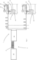
- Fig. 3 shows a more detailed representation of a device 1 according to the invention.
- the reference number 6 refers to a supply device which has the high-frequency generator device 62 and the alternating voltage distribution device 64.
- the voltage pulses are divided into two coating stations with a time offset.
- These coating stations 2, 4 each have a first electrode 22 or 42, which can be inserted into a container 10 to be coated.
- the coating stations 2, 4 each had a second electrode 24, 44, which is arranged outside the container 10. These second electrodes 24, 44 are preferably grounded here.
- the reference numeral 32 denotes a media reservoir, such as a reservoir for a gas mixture, such as a mixture of HMDSO + O 2 .
- the reference numeral 34 denotes a supply line for supplying the medium to the containers and the reference numeral 36 denotes a control device which controls the supply of the medium into the containers 10. SiO 2 is only created in the plasma in the container, more precisely between two plasma pulses.
Landscapes
- Chemical & Material Sciences (AREA)
- Engineering & Computer Science (AREA)
- Physics & Mathematics (AREA)
- Plasma & Fusion (AREA)
- Analytical Chemistry (AREA)
- Chemical Kinetics & Catalysis (AREA)
- General Chemical & Material Sciences (AREA)
- Materials Engineering (AREA)
- Mechanical Engineering (AREA)
- Metallurgy (AREA)
- Organic Chemistry (AREA)
- Inorganic Chemistry (AREA)
- Chemical Vapour Deposition (AREA)
- Plasma Technology (AREA)
- Details Of Rigid Or Semi-Rigid Containers (AREA)
Claims (15)
- Dispositif pour le revêtement d'objets (10) et en particulier de récipients (10) avec au moins un premier et un deuxième poste de revêtement (2, 4), dans lequel ces postes de revêtement (2, 4) présentent respectivement au moins une première électrode de revêtement (22, 42) et une deuxième électrode de revêtement (24, 44) et avec un équipement d'alimentation (6) pour l'alimentation électrique de respectivement au moins l'une des électrodes de revêtement (22, 24),
dans lequel
l'équipement d'alimentation (6) présente un équipement de générateur haute fréquence (62) pour la production d'impulsions de tension (P, P2, P4, P20, P40), dans lequel les impulsions de tension présentent une longueur temporelle qui est inférieure à 40 ms, et un équipement de répartition de tension alternative (64), lequel répartit ces impulsions de tension (P, P2, P4, P20, P40) sur respectivement au moins une électrode du premier poste de revêtement (2) et du deuxième poste de revêtement (4), dans lequel l'équipement de répartition de tension alternative est adapté pour et destiné à répartir les impulsions de tension (P, P2, P4, P20, P40) sur les électrodes de façon décalée dans le temps, dans lequel le dispositif présente un équipement de transport, lequel transporte les récipients et/ou les postes de revêtement le long d'un trajet de transport prédéfini. - Dispositif (1) selon la revendication 1,
dans lequel
l'équipement de répartition de tension alternative (64) est réalisé en tant que multiplexeur. - Dispositif (1) selon au moins l'une des revendications précédentes, dans lequel
le dispositif (1) présente un équipement de transport mobile et en particulier rotatif, sur lequel les postes de revêtement (2, 4) sont disposés. - Dispositif (1) selon au moins l'une des revendications précédentes,
dans lequel
les postes de revêtement (2, 4) sont disposés de manière fixe. - Dispositif (1) selon au moins l'une des revendications précédentes,
dans lequel
le dispositif présente un équipement d'amenée de milieu (32, 34, 36), lequel est adapté pour et destiné à amener un milieu coulant et en particulier gazeux au récipient. - Dispositif (1) selon au moins l'une des revendications précédentes,
dans lequel
l'équipement de générateur haute fréquence délivre la tension sous forme d'impulsions de tension (P, P2, P4, P20, P40). - Dispositif (1) selon la revendication précédente,
dans lequel
l'équipement de répartition de tension alternative répartit les impulsions délivrées par l'équipement de générateur haute fréquence respectivement intégralement sur les électrodes individuelles. - Dispositif (1) selon au moins l'une des revendications précédentes,
dans lequel
la puissance pouvant être injectée de l'équipement de générateur haute fréquence peut être adaptée sur la base d'une valeur de mesure de la puissance réfléchie. - Dispositif (1) selon la revendication précédente,
dans lequel
il comprend un équipement de commande avec un équipement de mémoire, au moyen duquel une valeur de consigne prédéfinie pour un processus de revêtement suivant peut être comparée à au moins une valeur de mesure d'un processus de revêtement précédent, dans lequel de préférence au moins une valeur de mesure est une valeur de mesure d'un paramètre qui est choisi dans un groupe, lequel comprend une puissance réfléchie, une puissance introduite, une différence entre une puissance introduite et une puissance réfléchie, la puissance injectée dans le plasma, une émission optique du plasma, un débit volumétrique de gaz, une composition de gaz, une température de la lance à gaz et une température d'une surface de récipient seuls ou en combinaison. - Dispositif (1) selon la revendication précédente,
dans lequel
il comprend un équipement d'évaluation, par lequel un facteur peut être déterminé, avec lequel un paramètre est intégré dans le calcul pour la détermination d'une puissance à injecter, dans lequel de préférence le facteur est variable de manière dynamique. - Dispositif (1) selon la revendication précédente,
dans lequel
l'équipement d'évaluation est un système IA pour la reconnaissance de motifs et pour l'adaptation du facteur sur la base de celle-ci. - Procédé pour le revêtement d'objets (10) et en particulier de récipients (10) avec au moins un premier et un deuxième poste de revêtement (2, 4), dans lequel ces postes de revêtement (2, 4) présentent respectivement au moins une première électrode de revêtement (22, 42) et une deuxième électrode de revêtement (24, 44) et dans lequel respectivement au moins l'une des électrodes de revêtement (22, 24) est alimentée en énergie électrique avec un équipement d'alimentation (6), dans lequel
l'équipement d'alimentation (6) fournit des impulsions de tension (P, P2, P4, P20, P40) au moyen d'un équipement de générateur haute fréquence (62), dans lequel les impulsions de tension présentent une longueur temporelle qui est inférieure à 40 ms, et un équipement de répartition de tension alternative (64) répartit ces impulsions de tension (P, P2, P4, P20, P40) sur respectivement au moins une électrode du premier poste de revêtement (2) et au moins une électrode du deuxième poste de revêtement (4), dans lequel l'équipement de répartition de tension alternative répartit les impulsions de tension (P, P2, P4, P20, P40) sur les électrodes de façon décalée dans le temps, dans lequel le dispositif présente un équipement de transport, lequel transporte les récipients et/ou les postes de revêtement le long d'un trajet de transport prédéfini. - Procédé selon la revendication 12,
dans lequel
l'équipement de générateur haute fréquence (62) délivre la tension alternative sous forme d'impulsions de tension. - Procédé selon la revendication précédente,
dans lequel
un équipement de commande commande l'équipement de générateur haute fréquence (62) de telle sorte que les impulsions de tension sont délivrées par intervalles de temps prédéfinis. - Procédé selon au moins l'une des revendications précédentes 12-14, dans lequel
l'équipement de répartition de tension alternative répartit les impulsions de tension de telle sorte qu'à un moment prédéfini pas plus d'un poste de revêtement (2, 4) est alimenté en tension.
Applications Claiming Priority (1)
| Application Number | Priority Date | Filing Date | Title |
|---|---|---|---|
| DE102018132700.5A DE102018132700A1 (de) | 2018-12-18 | 2018-12-18 | Vorrichtung und Verfahren zum Beschichten und insbesondere Plasmabeschichten von Behältnissen |
Publications (2)
| Publication Number | Publication Date |
|---|---|
| EP3671805A1 EP3671805A1 (fr) | 2020-06-24 |
| EP3671805B1 true EP3671805B1 (fr) | 2023-09-13 |
Family
ID=68944598
Family Applications (1)
| Application Number | Title | Priority Date | Filing Date |
|---|---|---|---|
| EP19217438.1A Active EP3671805B1 (fr) | 2018-12-18 | 2019-12-18 | Dispositif et procédé de revêtement et en particulier de revêtement plasma des récipients |
Country Status (4)
| Country | Link |
|---|---|
| US (1) | US11776790B2 (fr) |
| EP (1) | EP3671805B1 (fr) |
| CN (1) | CN111334783B (fr) |
| DE (1) | DE102018132700A1 (fr) |
Families Citing this family (2)
| Publication number | Priority date | Publication date | Assignee | Title |
|---|---|---|---|---|
| KR102886124B1 (ko) | 2019-07-29 | 2025-11-14 | 에이이에스 글로벌 홀딩스 피티이 리미티드 | 다수의 부하의 펄스 구동을 위한 채널 오프셋을 갖는 멀티플렉싱된 전력 발생기 출력 |
| DE102020119167A1 (de) * | 2020-07-21 | 2022-01-27 | Krones Aktiengesellschaft | Vorrichtung zum Beschichten von Behältnissen mit Wechseleinrichtung |
Citations (2)
| Publication number | Priority date | Publication date | Assignee | Title |
|---|---|---|---|---|
| DE4447977B4 (de) * | 1993-05-03 | 2009-09-10 | Oc Oerlikon Balzers Ag | Vorrichtung und Verfahren zur Plasmabehandlung von flachen Werkstücken, insbesondere flachen, aktiven Bildschirmen, sowie Verwendung der Vorrichtung |
| EP2151510A1 (fr) * | 2008-08-08 | 2010-02-10 | Krones AG | Dispositif et procédé destinés au traitement plasma de corps creux |
Family Cites Families (12)
| Publication number | Priority date | Publication date | Assignee | Title |
|---|---|---|---|---|
| DE19634795C2 (de) | 1996-08-29 | 1999-11-04 | Schott Glas | Plasma-CVD-Anlage mit einem Array von Mikrowellen-Plasmaelektroden und Plasma-CVD-Verfahren |
| WO2002013225A2 (fr) * | 2000-08-08 | 2002-02-14 | Tokyo Electron Limited | Procede et appareil d'amelioration de l'uniformite du traitement au plasma |
| JP4238015B2 (ja) | 2002-11-19 | 2009-03-11 | 大日本印刷株式会社 | プラスチック製容器の製造法 |
| JP4451392B2 (ja) * | 2003-01-16 | 2010-04-14 | 独立行政法人科学技術振興機構 | プラズマ発生装置 |
| US8025915B2 (en) * | 2006-01-11 | 2011-09-27 | Schott Ag | Method of preparing a macromolecule deterrent surface on a pharmaceutical package |
| DE102007037527B4 (de) * | 2006-11-10 | 2013-05-08 | Schott Ag | Verfahren zum Beschichten von Gegenständen mit Wechselschichten |
| JP5334787B2 (ja) * | 2009-10-09 | 2013-11-06 | 株式会社日立ハイテクノロジーズ | プラズマ処理装置 |
| JP5170216B2 (ja) | 2010-11-16 | 2013-03-27 | 株式会社デンソー | プラズマ発生装置 |
| DE102011104730A1 (de) * | 2011-06-16 | 2012-12-20 | Khs Corpoplast Gmbh | Verfahren zur Plasmabehandlung von Werkstücken sowie Werkstück mit Gasbarriereschicht |
| DE102012204690A1 (de) * | 2012-03-23 | 2013-09-26 | Krones Ag | Vorrichtung zum Plasmabeschichten von Füllgutbehältern, wie Flaschen |
| JP2018123370A (ja) * | 2017-01-31 | 2018-08-09 | アドバンストマテリアルテクノロジーズ株式会社 | プラズマcvd装置及び成膜方法 |
| DE102018204585A1 (de) | 2017-03-31 | 2018-10-04 | centrotherm international AG | Plasmagenerator, Plasma-Behandlungsvorrichtung und Verfahren zum gepulsten Bereitstellen von elektrischer Leistung |
-
2018
- 2018-12-18 DE DE102018132700.5A patent/DE102018132700A1/de not_active Withdrawn
-
2019
- 2019-12-06 US US16/705,298 patent/US11776790B2/en active Active
- 2019-12-13 CN CN201911282530.9A patent/CN111334783B/zh active Active
- 2019-12-18 EP EP19217438.1A patent/EP3671805B1/fr active Active
Patent Citations (2)
| Publication number | Priority date | Publication date | Assignee | Title |
|---|---|---|---|---|
| DE4447977B4 (de) * | 1993-05-03 | 2009-09-10 | Oc Oerlikon Balzers Ag | Vorrichtung und Verfahren zur Plasmabehandlung von flachen Werkstücken, insbesondere flachen, aktiven Bildschirmen, sowie Verwendung der Vorrichtung |
| EP2151510A1 (fr) * | 2008-08-08 | 2010-02-10 | Krones AG | Dispositif et procédé destinés au traitement plasma de corps creux |
Also Published As
| Publication number | Publication date |
|---|---|
| CN111334783A (zh) | 2020-06-26 |
| US11776790B2 (en) | 2023-10-03 |
| US20200194232A1 (en) | 2020-06-18 |
| EP3671805A1 (fr) | 2020-06-24 |
| DE102018132700A1 (de) | 2020-06-18 |
| CN111334783B (zh) | 2025-08-05 |
Similar Documents
| Publication | Publication Date | Title |
|---|---|---|
| DE19634795C2 (de) | Plasma-CVD-Anlage mit einem Array von Mikrowellen-Plasmaelektroden und Plasma-CVD-Verfahren | |
| EP1864313B1 (fr) | Generateur de plasma sous vide | |
| EP1921656A1 (fr) | Procédé et dispositif de dépôt chimique en phase vapeur assisté de plasma | |
| EP3671805B1 (fr) | Dispositif et procédé de revêtement et en particulier de revêtement plasma des récipients | |
| DE102008037159A1 (de) | Vorrichtung und Verfahren zur Plasmabehandlung von Hohlkörpern | |
| DE102009020436A1 (de) | Verfahren und Vorrichtung zur Plasmabehandlung eines flachen Substrats | |
| DE102006052061A1 (de) | Verfahren zur Ansteuerung von zumindest zwei HF-Leistungsgeneratoren | |
| EP2630273B1 (fr) | Procédé de traitement au plasma de pièces | |
| WO1999014390A2 (fr) | Procede de revetement de surfaces au moyen d'une installation dotee d'electrodes de depot par pulverisation | |
| EP3289113A1 (fr) | Procédé de fabrication de substrats revêtus | |
| WO2019121723A1 (fr) | Dispositif de traitement de récipients | |
| EP1753011A1 (fr) | Méthode de fournir les signaux de commande pour les générateurs de puissance à haute-fréquence | |
| EP3798158A1 (fr) | Dispositif de manipulation de conception modulaire pour récipients | |
| DE102020124030B4 (de) | Vorrichtung, System und Verfahren zur plasmaunterstützten chemischen Gasphasenabscheidung | |
| DE102008027363B4 (de) | Vorrichtung zur Behandlung großvolumiger Substrate im Plasma und Verfahren zur Anwendung | |
| EP0257620B1 (fr) | Procédé et dispositif pour former une couche par déposition chimique à plasma | |
| WO2019233750A1 (fr) | Source de plasma à micro-ondes linéaire comportant des espaces à plasma séparés | |
| WO2012119700A1 (fr) | Dispositif et procédé de traitement assisté par plasma d'au moins deux substrats | |
| WO2011064084A1 (fr) | Dispositif de production de plasma à l'aide de micro-ondes | |
| DE102009026249A1 (de) | Plasma unterstütztes Abscheideverfahren, Halbleitervorrichtung und Abscheidevorrichtung | |
| DE102008062619B4 (de) | Mikrowellenplasmaquelle und Verfahren zur Bildung eines linear langgestreckten Plasma bei Atmosphärendruckbedingen | |
| DE102004030523A1 (de) | Transportsystem für Nanopartikel und Verfahren zu dessen Betrieb | |
| WO2018224454A1 (fr) | Procédé pour le dépôt de delo | |
| DE102007021386A1 (de) | Kurztaktniederdruckplasmaanlage | |
| DE60023781T2 (de) | Apparat und Verfahren zur Herstellung von Halbleitervorrichtungen |
Legal Events
| Date | Code | Title | Description |
|---|---|---|---|
| PUAI | Public reference made under article 153(3) epc to a published international application that has entered the european phase |
Free format text: ORIGINAL CODE: 0009012 |
|
| STAA | Information on the status of an ep patent application or granted ep patent |
Free format text: STATUS: THE APPLICATION HAS BEEN PUBLISHED |
|
| AK | Designated contracting states |
Kind code of ref document: A1 Designated state(s): AL AT BE BG CH CY CZ DE DK EE ES FI FR GB GR HR HU IE IS IT LI LT LU LV MC MK MT NL NO PL PT RO RS SE SI SK SM TR |
|
| AX | Request for extension of the european patent |
Extension state: BA ME |
|
| STAA | Information on the status of an ep patent application or granted ep patent |
Free format text: STATUS: REQUEST FOR EXAMINATION WAS MADE |
|
| 17P | Request for examination filed |
Effective date: 20201216 |
|
| RBV | Designated contracting states (corrected) |
Designated state(s): AL AT BE BG CH CY CZ DE DK EE ES FI FR GB GR HR HU IE IS IT LI LT LU LV MC MK MT NL NO PL PT RO RS SE SI SK SM TR |
|
| STAA | Information on the status of an ep patent application or granted ep patent |
Free format text: STATUS: EXAMINATION IS IN PROGRESS |
|
| 17Q | First examination report despatched |
Effective date: 20211109 |
|
| GRAP | Despatch of communication of intention to grant a patent |
Free format text: ORIGINAL CODE: EPIDOSNIGR1 |
|
| STAA | Information on the status of an ep patent application or granted ep patent |
Free format text: STATUS: GRANT OF PATENT IS INTENDED |
|
| INTG | Intention to grant announced |
Effective date: 20230208 |
|
| GRAS | Grant fee paid |
Free format text: ORIGINAL CODE: EPIDOSNIGR3 |
|
| GRAJ | Information related to disapproval of communication of intention to grant by the applicant or resumption of examination proceedings by the epo deleted |
Free format text: ORIGINAL CODE: EPIDOSDIGR1 |
|
| GRAL | Information related to payment of fee for publishing/printing deleted |
Free format text: ORIGINAL CODE: EPIDOSDIGR3 |
|
| STAA | Information on the status of an ep patent application or granted ep patent |
Free format text: STATUS: EXAMINATION IS IN PROGRESS |
|
| P01 | Opt-out of the competence of the unified patent court (upc) registered |
Effective date: 20230523 |
|
| GRAP | Despatch of communication of intention to grant a patent |
Free format text: ORIGINAL CODE: EPIDOSNIGR1 |
|
| STAA | Information on the status of an ep patent application or granted ep patent |
Free format text: STATUS: GRANT OF PATENT IS INTENDED |
|
| INTC | Intention to grant announced (deleted) | ||
| GRAA | (expected) grant |
Free format text: ORIGINAL CODE: 0009210 |
|
| STAA | Information on the status of an ep patent application or granted ep patent |
Free format text: STATUS: THE PATENT HAS BEEN GRANTED |
|
| INTG | Intention to grant announced |
Effective date: 20230718 |
|
| AK | Designated contracting states |
Kind code of ref document: B1 Designated state(s): AL AT BE BG CH CY CZ DE DK EE ES FI FR GB GR HR HU IE IS IT LI LT LU LV MC MK MT NL NO PL PT RO RS SE SI SK SM TR |
|
| REG | Reference to a national code |
Ref country code: CH Ref legal event code: EP |
|
| REG | Reference to a national code |
Ref country code: DE Ref legal event code: R096 Ref document number: 502019009331 Country of ref document: DE |
|
| REG | Reference to a national code |
Ref country code: IE Ref legal event code: FG4D Free format text: LANGUAGE OF EP DOCUMENT: GERMAN |
|
| REG | Reference to a national code |
Ref country code: LT Ref legal event code: MG9D |
|
| REG | Reference to a national code |
Ref country code: NL Ref legal event code: MP Effective date: 20230913 |
|
| PG25 | Lapsed in a contracting state [announced via postgrant information from national office to epo] |
Ref country code: GR Free format text: LAPSE BECAUSE OF FAILURE TO SUBMIT A TRANSLATION OF THE DESCRIPTION OR TO PAY THE FEE WITHIN THE PRESCRIBED TIME-LIMIT Effective date: 20231214 |
|
| PG25 | Lapsed in a contracting state [announced via postgrant information from national office to epo] |
Ref country code: SE Free format text: LAPSE BECAUSE OF FAILURE TO SUBMIT A TRANSLATION OF THE DESCRIPTION OR TO PAY THE FEE WITHIN THE PRESCRIBED TIME-LIMIT Effective date: 20230913 Ref country code: RS Free format text: LAPSE BECAUSE OF FAILURE TO SUBMIT A TRANSLATION OF THE DESCRIPTION OR TO PAY THE FEE WITHIN THE PRESCRIBED TIME-LIMIT Effective date: 20230913 Ref country code: NO Free format text: LAPSE BECAUSE OF FAILURE TO SUBMIT A TRANSLATION OF THE DESCRIPTION OR TO PAY THE FEE WITHIN THE PRESCRIBED TIME-LIMIT Effective date: 20231213 Ref country code: LV Free format text: LAPSE BECAUSE OF FAILURE TO SUBMIT A TRANSLATION OF THE DESCRIPTION OR TO PAY THE FEE WITHIN THE PRESCRIBED TIME-LIMIT Effective date: 20230913 Ref country code: LT Free format text: LAPSE BECAUSE OF FAILURE TO SUBMIT A TRANSLATION OF THE DESCRIPTION OR TO PAY THE FEE WITHIN THE PRESCRIBED TIME-LIMIT Effective date: 20230913 Ref country code: HR Free format text: LAPSE BECAUSE OF FAILURE TO SUBMIT A TRANSLATION OF THE DESCRIPTION OR TO PAY THE FEE WITHIN THE PRESCRIBED TIME-LIMIT Effective date: 20230913 Ref country code: GR Free format text: LAPSE BECAUSE OF FAILURE TO SUBMIT A TRANSLATION OF THE DESCRIPTION OR TO PAY THE FEE WITHIN THE PRESCRIBED TIME-LIMIT Effective date: 20231214 Ref country code: FI Free format text: LAPSE BECAUSE OF FAILURE TO SUBMIT A TRANSLATION OF THE DESCRIPTION OR TO PAY THE FEE WITHIN THE PRESCRIBED TIME-LIMIT Effective date: 20230913 |
|
| PG25 | Lapsed in a contracting state [announced via postgrant information from national office to epo] |
Ref country code: NL Free format text: LAPSE BECAUSE OF FAILURE TO SUBMIT A TRANSLATION OF THE DESCRIPTION OR TO PAY THE FEE WITHIN THE PRESCRIBED TIME-LIMIT Effective date: 20230913 |
|
| PG25 | Lapsed in a contracting state [announced via postgrant information from national office to epo] |
Ref country code: IS Free format text: LAPSE BECAUSE OF FAILURE TO SUBMIT A TRANSLATION OF THE DESCRIPTION OR TO PAY THE FEE WITHIN THE PRESCRIBED TIME-LIMIT Effective date: 20240113 |
|
| PG25 | Lapsed in a contracting state [announced via postgrant information from national office to epo] |
Ref country code: ES Free format text: LAPSE BECAUSE OF FAILURE TO SUBMIT A TRANSLATION OF THE DESCRIPTION OR TO PAY THE FEE WITHIN THE PRESCRIBED TIME-LIMIT Effective date: 20230913 |
|
| PG25 | Lapsed in a contracting state [announced via postgrant information from national office to epo] |
Ref country code: SM Free format text: LAPSE BECAUSE OF FAILURE TO SUBMIT A TRANSLATION OF THE DESCRIPTION OR TO PAY THE FEE WITHIN THE PRESCRIBED TIME-LIMIT Effective date: 20230913 Ref country code: RO Free format text: LAPSE BECAUSE OF FAILURE TO SUBMIT A TRANSLATION OF THE DESCRIPTION OR TO PAY THE FEE WITHIN THE PRESCRIBED TIME-LIMIT Effective date: 20230913 Ref country code: IS Free format text: LAPSE BECAUSE OF FAILURE TO SUBMIT A TRANSLATION OF THE DESCRIPTION OR TO PAY THE FEE WITHIN THE PRESCRIBED TIME-LIMIT Effective date: 20240113 Ref country code: ES Free format text: LAPSE BECAUSE OF FAILURE TO SUBMIT A TRANSLATION OF THE DESCRIPTION OR TO PAY THE FEE WITHIN THE PRESCRIBED TIME-LIMIT Effective date: 20230913 Ref country code: EE Free format text: LAPSE BECAUSE OF FAILURE TO SUBMIT A TRANSLATION OF THE DESCRIPTION OR TO PAY THE FEE WITHIN THE PRESCRIBED TIME-LIMIT Effective date: 20230913 Ref country code: CZ Free format text: LAPSE BECAUSE OF FAILURE TO SUBMIT A TRANSLATION OF THE DESCRIPTION OR TO PAY THE FEE WITHIN THE PRESCRIBED TIME-LIMIT Effective date: 20230913 Ref country code: SK Free format text: LAPSE BECAUSE OF FAILURE TO SUBMIT A TRANSLATION OF THE DESCRIPTION OR TO PAY THE FEE WITHIN THE PRESCRIBED TIME-LIMIT Effective date: 20230913 Ref country code: PT Free format text: LAPSE BECAUSE OF FAILURE TO SUBMIT A TRANSLATION OF THE DESCRIPTION OR TO PAY THE FEE WITHIN THE PRESCRIBED TIME-LIMIT Effective date: 20240115 |
|
| PG25 | Lapsed in a contracting state [announced via postgrant information from national office to epo] |
Ref country code: PL Free format text: LAPSE BECAUSE OF FAILURE TO SUBMIT A TRANSLATION OF THE DESCRIPTION OR TO PAY THE FEE WITHIN THE PRESCRIBED TIME-LIMIT Effective date: 20230913 |
|
| REG | Reference to a national code |
Ref country code: DE Ref legal event code: R097 Ref document number: 502019009331 Country of ref document: DE |
|
| PG25 | Lapsed in a contracting state [announced via postgrant information from national office to epo] |
Ref country code: DK Free format text: LAPSE BECAUSE OF FAILURE TO SUBMIT A TRANSLATION OF THE DESCRIPTION OR TO PAY THE FEE WITHIN THE PRESCRIBED TIME-LIMIT Effective date: 20230913 |
|
| PLBE | No opposition filed within time limit |
Free format text: ORIGINAL CODE: 0009261 |
|
| STAA | Information on the status of an ep patent application or granted ep patent |
Free format text: STATUS: NO OPPOSITION FILED WITHIN TIME LIMIT |
|
| PG25 | Lapsed in a contracting state [announced via postgrant information from national office to epo] |
Ref country code: DK Free format text: LAPSE BECAUSE OF FAILURE TO SUBMIT A TRANSLATION OF THE DESCRIPTION OR TO PAY THE FEE WITHIN THE PRESCRIBED TIME-LIMIT Effective date: 20230913 |
|
| REG | Reference to a national code |
Ref country code: CH Ref legal event code: PL |
|
| 26N | No opposition filed |
Effective date: 20240614 |
|
| PG25 | Lapsed in a contracting state [announced via postgrant information from national office to epo] |
Ref country code: LU Free format text: LAPSE BECAUSE OF NON-PAYMENT OF DUE FEES Effective date: 20231218 |
|
| PG25 | Lapsed in a contracting state [announced via postgrant information from national office to epo] |
Ref country code: MC Free format text: LAPSE BECAUSE OF FAILURE TO SUBMIT A TRANSLATION OF THE DESCRIPTION OR TO PAY THE FEE WITHIN THE PRESCRIBED TIME-LIMIT Effective date: 20230913 |
|
| GBPC | Gb: european patent ceased through non-payment of renewal fee |
Effective date: 20231218 |
|
| REG | Reference to a national code |
Ref country code: BE Ref legal event code: MM Effective date: 20231231 |
|
| PG25 | Lapsed in a contracting state [announced via postgrant information from national office to epo] |
Ref country code: MC Free format text: LAPSE BECAUSE OF FAILURE TO SUBMIT A TRANSLATION OF THE DESCRIPTION OR TO PAY THE FEE WITHIN THE PRESCRIBED TIME-LIMIT Effective date: 20230913 Ref country code: LU Free format text: LAPSE BECAUSE OF NON-PAYMENT OF DUE FEES Effective date: 20231218 |
|
| REG | Reference to a national code |
Ref country code: IE Ref legal event code: MM4A |
|
| PG25 | Lapsed in a contracting state [announced via postgrant information from national office to epo] |
Ref country code: IE Free format text: LAPSE BECAUSE OF NON-PAYMENT OF DUE FEES Effective date: 20231218 |
|
| PG25 | Lapsed in a contracting state [announced via postgrant information from national office to epo] |
Ref country code: GB Free format text: LAPSE BECAUSE OF NON-PAYMENT OF DUE FEES Effective date: 20231218 |
|
| PG25 | Lapsed in a contracting state [announced via postgrant information from national office to epo] |
Ref country code: BE Free format text: LAPSE BECAUSE OF NON-PAYMENT OF DUE FEES Effective date: 20231231 |
|
| PG25 | Lapsed in a contracting state [announced via postgrant information from national office to epo] |
Ref country code: CH Free format text: LAPSE BECAUSE OF NON-PAYMENT OF DUE FEES Effective date: 20231231 |
|
| PG25 | Lapsed in a contracting state [announced via postgrant information from national office to epo] |
Ref country code: SI Free format text: LAPSE BECAUSE OF FAILURE TO SUBMIT A TRANSLATION OF THE DESCRIPTION OR TO PAY THE FEE WITHIN THE PRESCRIBED TIME-LIMIT Effective date: 20230913 |
|
| PG25 | Lapsed in a contracting state [announced via postgrant information from national office to epo] |
Ref country code: SI Free format text: LAPSE BECAUSE OF FAILURE TO SUBMIT A TRANSLATION OF THE DESCRIPTION OR TO PAY THE FEE WITHIN THE PRESCRIBED TIME-LIMIT Effective date: 20230913 Ref country code: IE Free format text: LAPSE BECAUSE OF NON-PAYMENT OF DUE FEES Effective date: 20231218 Ref country code: GB Free format text: LAPSE BECAUSE OF NON-PAYMENT OF DUE FEES Effective date: 20231218 Ref country code: CH Free format text: LAPSE BECAUSE OF NON-PAYMENT OF DUE FEES Effective date: 20231231 Ref country code: BE Free format text: LAPSE BECAUSE OF NON-PAYMENT OF DUE FEES Effective date: 20231231 |
|
| PG25 | Lapsed in a contracting state [announced via postgrant information from national office to epo] |
Ref country code: BG Free format text: LAPSE BECAUSE OF FAILURE TO SUBMIT A TRANSLATION OF THE DESCRIPTION OR TO PAY THE FEE WITHIN THE PRESCRIBED TIME-LIMIT Effective date: 20230913 |
|
| PG25 | Lapsed in a contracting state [announced via postgrant information from national office to epo] |
Ref country code: BG Free format text: LAPSE BECAUSE OF FAILURE TO SUBMIT A TRANSLATION OF THE DESCRIPTION OR TO PAY THE FEE WITHIN THE PRESCRIBED TIME-LIMIT Effective date: 20230913 |
|
| PG25 | Lapsed in a contracting state [announced via postgrant information from national office to epo] |
Ref country code: CY Free format text: LAPSE BECAUSE OF FAILURE TO SUBMIT A TRANSLATION OF THE DESCRIPTION OR TO PAY THE FEE WITHIN THE PRESCRIBED TIME-LIMIT; INVALID AB INITIO Effective date: 20191218 |
|
| PG25 | Lapsed in a contracting state [announced via postgrant information from national office to epo] |
Ref country code: HU Free format text: LAPSE BECAUSE OF FAILURE TO SUBMIT A TRANSLATION OF THE DESCRIPTION OR TO PAY THE FEE WITHIN THE PRESCRIBED TIME-LIMIT; INVALID AB INITIO Effective date: 20191218 |
|
| PG25 | Lapsed in a contracting state [announced via postgrant information from national office to epo] |
Ref country code: TR Free format text: LAPSE BECAUSE OF FAILURE TO SUBMIT A TRANSLATION OF THE DESCRIPTION OR TO PAY THE FEE WITHIN THE PRESCRIBED TIME-LIMIT Effective date: 20230913 |
|
| PGFP | Annual fee paid to national office [announced via postgrant information from national office to epo] |
Ref country code: DE Payment date: 20251104 Year of fee payment: 7 |
|
| PGFP | Annual fee paid to national office [announced via postgrant information from national office to epo] |
Ref country code: IT Payment date: 20251121 Year of fee payment: 7 |
|
| PGFP | Annual fee paid to national office [announced via postgrant information from national office to epo] |
Ref country code: FR Payment date: 20251110 Year of fee payment: 7 |
|
| REG | Reference to a national code |
Ref country code: AT Ref legal event code: MM01 Ref document number: 1612176 Country of ref document: AT Kind code of ref document: T Effective date: 20241218 |
|
| PG25 | Lapsed in a contracting state [announced via postgrant information from national office to epo] |
Ref country code: AT Free format text: LAPSE BECAUSE OF NON-PAYMENT OF DUE FEES Effective date: 20241218 |
|
| PGFP | Annual fee paid to national office [announced via postgrant information from national office to epo] |
Ref country code: AT Payment date: 20260410 Year of fee payment: 5 |