EP3671886B1 - Batterie secondaire de type poche et poche pour batterie secondaire - Google Patents
Batterie secondaire de type poche et poche pour batterie secondaire Download PDFInfo
- Publication number
- EP3671886B1 EP3671886B1 EP19854713.5A EP19854713A EP3671886B1 EP 3671886 B1 EP3671886 B1 EP 3671886B1 EP 19854713 A EP19854713 A EP 19854713A EP 3671886 B1 EP3671886 B1 EP 3671886B1
- Authority
- EP
- European Patent Office
- Prior art keywords
- layer
- pouch
- negative electrode
- metal foil
- secondary battery
- Prior art date
- Legal status (The legal status is an assumption and is not a legal conclusion. Google has not performed a legal analysis and makes no representation as to the accuracy of the status listed.)
- Active
Links
Images




Classifications
-
- H—ELECTRICITY
- H01—ELECTRIC ELEMENTS
- H01M—PROCESSES OR MEANS, e.g. BATTERIES, FOR THE DIRECT CONVERSION OF CHEMICAL ENERGY INTO ELECTRICAL ENERGY
- H01M50/00—Constructional details or processes of manufacture of the non-active parts of electrochemical cells other than fuel cells, e.g. hybrid cells
- H01M50/10—Primary casings; Jackets or wrappings
- H01M50/102—Primary casings; Jackets or wrappings characterised by their shape or physical structure
- H01M50/105—Pouches or flexible bags
-
- H—ELECTRICITY
- H01—ELECTRIC ELEMENTS
- H01M—PROCESSES OR MEANS, e.g. BATTERIES, FOR THE DIRECT CONVERSION OF CHEMICAL ENERGY INTO ELECTRICAL ENERGY
- H01M50/00—Constructional details or processes of manufacture of the non-active parts of electrochemical cells other than fuel cells, e.g. hybrid cells
- H01M50/10—Primary casings; Jackets or wrappings
- H01M50/116—Primary casings; Jackets or wrappings characterised by the material
- H01M50/124—Primary casings; Jackets or wrappings characterised by the material having a layered structure
-
- H—ELECTRICITY
- H01—ELECTRIC ELEMENTS
- H01M—PROCESSES OR MEANS, e.g. BATTERIES, FOR THE DIRECT CONVERSION OF CHEMICAL ENERGY INTO ELECTRICAL ENERGY
- H01M50/00—Constructional details or processes of manufacture of the non-active parts of electrochemical cells other than fuel cells, e.g. hybrid cells
- H01M50/10—Primary casings; Jackets or wrappings
- H01M50/116—Primary casings; Jackets or wrappings characterised by the material
- H01M50/124—Primary casings; Jackets or wrappings characterised by the material having a layered structure
- H01M50/126—Primary casings; Jackets or wrappings characterised by the material having a layered structure comprising three or more layers
- H01M50/129—Primary casings; Jackets or wrappings characterised by the material having a layered structure comprising three or more layers with two or more layers of only organic material
-
- B—PERFORMING OPERATIONS; TRANSPORTING
- B32—LAYERED PRODUCTS
- B32B—LAYERED PRODUCTS, i.e. PRODUCTS BUILT-UP OF STRATA OF FLAT OR NON-FLAT, e.g. CELLULAR OR HONEYCOMB, FORM
- B32B15/00—Layered products comprising a layer of metal
- B32B15/04—Layered products comprising a layer of metal comprising metal as the main or only constituent of a layer, which is next to another layer of the same or of a different material
-
- B—PERFORMING OPERATIONS; TRANSPORTING
- B32—LAYERED PRODUCTS
- B32B—LAYERED PRODUCTS, i.e. PRODUCTS BUILT-UP OF STRATA OF FLAT OR NON-FLAT, e.g. CELLULAR OR HONEYCOMB, FORM
- B32B15/00—Layered products comprising a layer of metal
- B32B15/04—Layered products comprising a layer of metal comprising metal as the main or only constituent of a layer, which is next to another layer of the same or of a different material
- B32B15/08—Layered products comprising a layer of metal comprising metal as the main or only constituent of a layer, which is next to another layer of the same or of a different material of synthetic resin
- B32B15/09—Layered products comprising a layer of metal comprising metal as the main or only constituent of a layer, which is next to another layer of the same or of a different material of synthetic resin comprising polyesters
-
- B—PERFORMING OPERATIONS; TRANSPORTING
- B32—LAYERED PRODUCTS
- B32B—LAYERED PRODUCTS, i.e. PRODUCTS BUILT-UP OF STRATA OF FLAT OR NON-FLAT, e.g. CELLULAR OR HONEYCOMB, FORM
- B32B15/00—Layered products comprising a layer of metal
- B32B15/20—Layered products comprising a layer of metal comprising aluminium or copper
-
- H—ELECTRICITY
- H01—ELECTRIC ELEMENTS
- H01M—PROCESSES OR MEANS, e.g. BATTERIES, FOR THE DIRECT CONVERSION OF CHEMICAL ENERGY INTO ELECTRICAL ENERGY
- H01M50/00—Constructional details or processes of manufacture of the non-active parts of electrochemical cells other than fuel cells, e.g. hybrid cells
- H01M50/10—Primary casings; Jackets or wrappings
- H01M50/116—Primary casings; Jackets or wrappings characterised by the material
- H01M50/117—Inorganic material
- H01M50/119—Metals
-
- H—ELECTRICITY
- H01—ELECTRIC ELEMENTS
- H01M—PROCESSES OR MEANS, e.g. BATTERIES, FOR THE DIRECT CONVERSION OF CHEMICAL ENERGY INTO ELECTRICAL ENERGY
- H01M50/00—Constructional details or processes of manufacture of the non-active parts of electrochemical cells other than fuel cells, e.g. hybrid cells
- H01M50/10—Primary casings; Jackets or wrappings
- H01M50/116—Primary casings; Jackets or wrappings characterised by the material
- H01M50/121—Organic material
-
- H—ELECTRICITY
- H01—ELECTRIC ELEMENTS
- H01M—PROCESSES OR MEANS, e.g. BATTERIES, FOR THE DIRECT CONVERSION OF CHEMICAL ENERGY INTO ELECTRICAL ENERGY
- H01M50/00—Constructional details or processes of manufacture of the non-active parts of electrochemical cells other than fuel cells, e.g. hybrid cells
- H01M50/10—Primary casings; Jackets or wrappings
- H01M50/116—Primary casings; Jackets or wrappings characterised by the material
- H01M50/124—Primary casings; Jackets or wrappings characterised by the material having a layered structure
- H01M50/1243—Primary casings; Jackets or wrappings characterised by the material having a layered structure characterised by the internal coating on the casing
-
- H—ELECTRICITY
- H01—ELECTRIC ELEMENTS
- H01M—PROCESSES OR MEANS, e.g. BATTERIES, FOR THE DIRECT CONVERSION OF CHEMICAL ENERGY INTO ELECTRICAL ENERGY
- H01M50/00—Constructional details or processes of manufacture of the non-active parts of electrochemical cells other than fuel cells, e.g. hybrid cells
- H01M50/10—Primary casings; Jackets or wrappings
- H01M50/116—Primary casings; Jackets or wrappings characterised by the material
- H01M50/124—Primary casings; Jackets or wrappings characterised by the material having a layered structure
- H01M50/1245—Primary casings; Jackets or wrappings characterised by the material having a layered structure characterised by the external coating on the casing
-
- H—ELECTRICITY
- H01—ELECTRIC ELEMENTS
- H01M—PROCESSES OR MEANS, e.g. BATTERIES, FOR THE DIRECT CONVERSION OF CHEMICAL ENERGY INTO ELECTRICAL ENERGY
- H01M50/00—Constructional details or processes of manufacture of the non-active parts of electrochemical cells other than fuel cells, e.g. hybrid cells
- H01M50/10—Primary casings; Jackets or wrappings
- H01M50/116—Primary casings; Jackets or wrappings characterised by the material
- H01M50/124—Primary casings; Jackets or wrappings characterised by the material having a layered structure
- H01M50/126—Primary casings; Jackets or wrappings characterised by the material having a layered structure comprising three or more layers
- H01M50/128—Primary casings; Jackets or wrappings characterised by the material having a layered structure comprising three or more layers with two or more layers of only inorganic material
-
- H—ELECTRICITY
- H01—ELECTRIC ELEMENTS
- H01M—PROCESSES OR MEANS, e.g. BATTERIES, FOR THE DIRECT CONVERSION OF CHEMICAL ENERGY INTO ELECTRICAL ENERGY
- H01M50/00—Constructional details or processes of manufacture of the non-active parts of electrochemical cells other than fuel cells, e.g. hybrid cells
- H01M50/10—Primary casings; Jackets or wrappings
- H01M50/14—Primary casings; Jackets or wrappings for protecting against damage caused by external factors
-
- H—ELECTRICITY
- H01—ELECTRIC ELEMENTS
- H01M—PROCESSES OR MEANS, e.g. BATTERIES, FOR THE DIRECT CONVERSION OF CHEMICAL ENERGY INTO ELECTRICAL ENERGY
- H01M50/00—Constructional details or processes of manufacture of the non-active parts of electrochemical cells other than fuel cells, e.g. hybrid cells
- H01M50/10—Primary casings; Jackets or wrappings
- H01M50/172—Arrangements of electric connectors penetrating the casing
- H01M50/174—Arrangements of electric connectors penetrating the casing adapted for the shape of the cells
- H01M50/178—Arrangements of electric connectors penetrating the casing adapted for the shape of the cells for pouch or flexible bag cells
-
- H—ELECTRICITY
- H01—ELECTRIC ELEMENTS
- H01M—PROCESSES OR MEANS, e.g. BATTERIES, FOR THE DIRECT CONVERSION OF CHEMICAL ENERGY INTO ELECTRICAL ENERGY
- H01M50/00—Constructional details or processes of manufacture of the non-active parts of electrochemical cells other than fuel cells, e.g. hybrid cells
- H01M50/50—Current conducting connections for cells or batteries
- H01M50/531—Electrode connections inside a battery casing
-
- H—ELECTRICITY
- H01—ELECTRIC ELEMENTS
- H01M—PROCESSES OR MEANS, e.g. BATTERIES, FOR THE DIRECT CONVERSION OF CHEMICAL ENERGY INTO ELECTRICAL ENERGY
- H01M50/00—Constructional details or processes of manufacture of the non-active parts of electrochemical cells other than fuel cells, e.g. hybrid cells
- H01M50/50—Current conducting connections for cells or batteries
- H01M50/531—Electrode connections inside a battery casing
- H01M50/536—Electrode connections inside a battery casing characterised by the method of fixing the leads to the electrodes, e.g. by welding
-
- H—ELECTRICITY
- H01—ELECTRIC ELEMENTS
- H01M—PROCESSES OR MEANS, e.g. BATTERIES, FOR THE DIRECT CONVERSION OF CHEMICAL ENERGY INTO ELECTRICAL ENERGY
- H01M50/00—Constructional details or processes of manufacture of the non-active parts of electrochemical cells other than fuel cells, e.g. hybrid cells
- H01M50/50—Current conducting connections for cells or batteries
- H01M50/543—Terminals
- H01M50/547—Terminals characterised by the disposition of the terminals on the cells
- H01M50/55—Terminals characterised by the disposition of the terminals on the cells on the same side of the cell
-
- H—ELECTRICITY
- H01—ELECTRIC ELEMENTS
- H01M—PROCESSES OR MEANS, e.g. BATTERIES, FOR THE DIRECT CONVERSION OF CHEMICAL ENERGY INTO ELECTRICAL ENERGY
- H01M50/00—Constructional details or processes of manufacture of the non-active parts of electrochemical cells other than fuel cells, e.g. hybrid cells
- H01M50/50—Current conducting connections for cells or batteries
- H01M50/543—Terminals
- H01M50/552—Terminals characterised by their shape
- H01M50/553—Terminals adapted for prismatic, pouch or rectangular cells
- H01M50/557—Plate-shaped terminals
-
- H—ELECTRICITY
- H01—ELECTRIC ELEMENTS
- H01M—PROCESSES OR MEANS, e.g. BATTERIES, FOR THE DIRECT CONVERSION OF CHEMICAL ENERGY INTO ELECTRICAL ENERGY
- H01M50/00—Constructional details or processes of manufacture of the non-active parts of electrochemical cells other than fuel cells, e.g. hybrid cells
- H01M50/50—Current conducting connections for cells or batteries
- H01M50/543—Terminals
- H01M50/562—Terminals characterised by the material
-
- B—PERFORMING OPERATIONS; TRANSPORTING
- B32—LAYERED PRODUCTS
- B32B—LAYERED PRODUCTS, i.e. PRODUCTS BUILT-UP OF STRATA OF FLAT OR NON-FLAT, e.g. CELLULAR OR HONEYCOMB, FORM
- B32B2307/00—Properties of the layers or laminate
- B32B2307/20—Properties of the layers or laminate having particular electrical or magnetic properties, e.g. piezoelectric
- B32B2307/206—Insulating
-
- B—PERFORMING OPERATIONS; TRANSPORTING
- B32—LAYERED PRODUCTS
- B32B—LAYERED PRODUCTS, i.e. PRODUCTS BUILT-UP OF STRATA OF FLAT OR NON-FLAT, e.g. CELLULAR OR HONEYCOMB, FORM
- B32B2307/00—Properties of the layers or laminate
- B32B2307/70—Other properties
- B32B2307/724—Permeability to gases, adsorption
- B32B2307/7242—Non-permeable
-
- B—PERFORMING OPERATIONS; TRANSPORTING
- B32—LAYERED PRODUCTS
- B32B—LAYERED PRODUCTS, i.e. PRODUCTS BUILT-UP OF STRATA OF FLAT OR NON-FLAT, e.g. CELLULAR OR HONEYCOMB, FORM
- B32B2439/00—Containers; Receptacles
- B32B2439/40—Closed containers
- B32B2439/46—Bags
-
- B—PERFORMING OPERATIONS; TRANSPORTING
- B32—LAYERED PRODUCTS
- B32B—LAYERED PRODUCTS, i.e. PRODUCTS BUILT-UP OF STRATA OF FLAT OR NON-FLAT, e.g. CELLULAR OR HONEYCOMB, FORM
- B32B2457/00—Electrical equipment
- B32B2457/10—Batteries
-
- H—ELECTRICITY
- H01—ELECTRIC ELEMENTS
- H01M—PROCESSES OR MEANS, e.g. BATTERIES, FOR THE DIRECT CONVERSION OF CHEMICAL ENERGY INTO ELECTRICAL ENERGY
- H01M2220/00—Batteries for particular applications
- H01M2220/20—Batteries in motive systems, e.g. vehicle, ship, plane
-
- H—ELECTRICITY
- H01—ELECTRIC ELEMENTS
- H01M—PROCESSES OR MEANS, e.g. BATTERIES, FOR THE DIRECT CONVERSION OF CHEMICAL ENERGY INTO ELECTRICAL ENERGY
- H01M2220/00—Batteries for particular applications
- H01M2220/30—Batteries in portable systems, e.g. mobile phone, laptop
-
- Y—GENERAL TAGGING OF NEW TECHNOLOGICAL DEVELOPMENTS; GENERAL TAGGING OF CROSS-SECTIONAL TECHNOLOGIES SPANNING OVER SEVERAL SECTIONS OF THE IPC; TECHNICAL SUBJECTS COVERED BY FORMER USPC CROSS-REFERENCE ART COLLECTIONS [XRACs] AND DIGESTS
- Y02—TECHNOLOGIES OR APPLICATIONS FOR MITIGATION OR ADAPTATION AGAINST CLIMATE CHANGE
- Y02E—REDUCTION OF GREENHOUSE GAS [GHG] EMISSIONS, RELATED TO ENERGY GENERATION, TRANSMISSION OR DISTRIBUTION
- Y02E60/00—Enabling technologies; Technologies with a potential or indirect contribution to GHG emissions mitigation
- Y02E60/10—Energy storage using batteries
-
- Y—GENERAL TAGGING OF NEW TECHNOLOGICAL DEVELOPMENTS; GENERAL TAGGING OF CROSS-SECTIONAL TECHNOLOGIES SPANNING OVER SEVERAL SECTIONS OF THE IPC; TECHNICAL SUBJECTS COVERED BY FORMER USPC CROSS-REFERENCE ART COLLECTIONS [XRACs] AND DIGESTS
- Y02—TECHNOLOGIES OR APPLICATIONS FOR MITIGATION OR ADAPTATION AGAINST CLIMATE CHANGE
- Y02P—CLIMATE CHANGE MITIGATION TECHNOLOGIES IN THE PRODUCTION OR PROCESSING OF GOODS
- Y02P70/00—Climate change mitigation technologies in the production process for final industrial or consumer products
- Y02P70/50—Manufacturing or production processes characterised by the final manufactured product
Definitions
- the present invention relates to a pouch-type secondary battery, according to claim 1 and a pouch for a pouch-type secondary battery, according to claim 10, that reduces a heat generation rate and easily releases heat to the outside to reduce a risk of explosion even if a sharp nail passes therethrough, and a pouch for a secondary battery.
- secondary batteries include nickelcadmium batteries, nickel-hydrogen batteries, lithium ion batteries, and lithium ion polymer batteries.
- Such a secondary battery is being applied to and used in small-sized products such as digital cameras, P-DVDs, MP3Ps, mobile phones, PDAs, portable game devices, power tools, E-bikes, and the like as well as large-sized products requiring high power such as electric vehicles and hybrid vehicles, power storage devices for storing surplus power or renewable energy, and backup power storage devices.
- Such a secondary battery is classified into a pouch type secondary battery and a can type secondary battery according to a material of a case accommodating the electrode assembly.
- a pouch type secondary battery an electrode assembly is accommodated in a pouch made of a flexible polymer material.
- an electrode assembly is accommodated in a case made of a metal or plastic material.
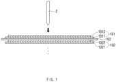
- FIG. 1 is a schematic view illustrating a state in which a nail 2 approaches an electrode assembly 10 according to the related art
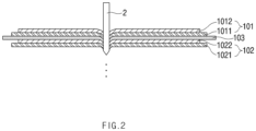
- FIG. 2 is a schematic view illustrating a state in which the nail 2 passes through the electrode assembly 10 according to the related art.
- the electrode assembly 10 To manufacture the electrode assembly 10, first, slurry of a positive electrode active material 1012 is applied to a positive electrode collector 1011, and slurry of a negative electrode active material 1022 is applied to a negative electrode collector 1021 to manufacture a positive electrode 101 and a negative electrode 102. Also, a separator 103 is disposed between the positive electrode 101 and the negative electrode 102, which are manufactured, and then, the positive electrode 101, the separator 103, and the negative electrode 102 are laminated to manufacture the electrode assembly 10 as illustrated in FIG. 1 . Although only one unit cell in which one positive electrode 101, one negative electrode 102, and one separator 103 are laminated is illustrated in FIG. 1 , the electrode assembly 10 is not limited thereto. For example, a plurality of unit cells may be further laminated.
- a secondary battery 1 When the electrode assembly 10 is accommodated in a case to be sealed, a secondary battery 1 is manufactured. However, while the secondary battery 1 is actually used, an accident may occur due to a collision with the outside. For example, a sharp object may pass through the secondary battery 1, and thus, the positive electrode 101 and the negative electrode 102 may directly contact each other to cause short circuit. Due to the short circuit, a large amount of gas may be generated at a high speed in a short time, and a high temperature rise may occur. Furthermore, large explosion may occur to lead to a major accident.
- a penetration test of a nail 2, in which the nail 2 is penetrated to determine an explosion risk is performed as one of safety tests.
- the secondary battery 1 may reach the highest temperature quickly when the positive electrode collector 1011 and the negative electrode active material 1022 contact each other, and thus, large explosion may occur.
- the contact between the positive electrode collector 1011 and the negative electrode active material 1022 is known as the most dangerous contact.
- the positive electrode 101 is laminated on the outermost side of the electrode assembly 10, as illustrated in FIG. 2 , there is a problem that possibility of occurrence of the large explosion is very high because the positive electrode collector 1011 and the negative electrode active material 1022 are the closest to each other.
- a problem to be solved by the present invention is to provide a pouch-type secondary battery that reduces a heat generation rate and easily releases heat to the outside to reduce a risk of explosion even if a sharp nail passes therethrough, and a pouch for a secondary battery.
- a pouch-type secondary battery includes: an electrode assembly (10) in which a positive electrode (101), a separator (103), and a negative electrode (102) are laminated; and a pouch comprising an upper pouch (131) and a lower pouch (132) and configured to accommodate the electrode assembly (10), wherein the pouch comprises: a surface protection layer (1352) made of a first polymer and formed at an outermost layer; a sealant layer (1353) made of a second polymer and formed at an innermost layer; a gas barrier layer (1351) made of a first metal and laminated between the surface protection layer and the sealant layer; and a metal foil layer (1354) made of a second metal, laminated between the surface protection layer and the sealant layer, and connected to the negative electrode of the electrode assembly, wherein the metal foil layer (1354) is connected to a negative electrode lead extending from the negative electrode so as to be connected to the negative electrode, and portions of the surface protection layer, the sealant layer, and the gas barrier layer
- the negative electrode lead may be welded and connected to the metal foil layer exposed through the specific area.
- the pouch-type secondary battery may further include an insulation layer, which insulates the gas barrier layer from the metal foil layer, between the gas barrier layer and the metal foil layer.
- the metal foil layer may be clad-rolled together with the gas barrier layer.
- the first polymer may include polyethylene terephthalate (PET).
- PET polyethylene terephthalate
- the first metal may include aluminum.
- the second metal may include the same kind of metal as a metal contained in a negative electrode collector of the negative electrode.
- the second metal may include copper.
- the second polymer may include polypropylene.
- a pouch for a pouch-type secondary battery which is configured to accommodate an electrode assembly in which a positive electrode, a separator, and a negative electrode are laminated, according to an embodiment of the present invention includes: a surface protection layer made of a first polymer and formed at an outermost layer; a sealant layer made of a second polymer and formed at an innermost layer; a gas barrier layer made of a first metal and laminated between the surface protection layer and the sealant layer; and a metal foil layer made of a second metal, laminated between the surface protection layer and the sealant layer, and connected to the negative electrode of the electrode assembly, wherein portions of the surface protection layer, the sealant layer, and the gas barrier layer are removed from a specific area to expose the metal foil layer to the outside and the specific area corresponds to an area on which a negative electrode lead (122) extending from the negative electrode exists in the upper pouch (131) and the lower pouch (132) when the electrode assembly is accommodated.
- the pouch for the pouch-type secondary battery may further include an insulation layer, which insulates the gas barrier layer from the metal foil layer, between the gas barrier layer and the metal foil layer.
- the metal foil layer may be clad-rolled together with the gas barrier layer.
- the embodiments of the present invention may have at least the following effects.
- the short circuit between the metal foil layer and the positive electrode active material may be induced first before the most dangerous short circuit between the positive electrode collector and the negative electrode active material to reduce the heat generation rate and easily release the heat to the outside, thereby reducing the risk of the explosion.
- FIG. 3 is an assembled view of a secondary battery 1 according to an embodiment of the present invention.
- slurry of a positive electrode active material 1012 is applied to a positive electrode collector 1011
- slurry of a negative electrode active material 1022 is applied to a negative electrode collector 1021 to manufacture a positive electrode 101 and a negative electrode 102.
- the positive electrode 101 and the negative electrode 102 may be laminated on both sides of a separator 103 to manufacture an electrode assembly 10 having a predetermined shape.
- the electrode assembly 10 may be accommodated in a battery case, and then, an electrolyte may be injected into the battery case to seal the battery case.
- the electrode assembly 10 includes an electrode tab 11.
- the electrode tab 11 is connected to each of the positive electrode 101 and the negative electrode 102 of the electrode assembly 10 to protrude to the outside of the electrode assembly 10, thereby providing a path, through which electrons move, between the inside and outside of the electrode assembly 10.
- the electrode collector of the electrode assembly 10 is constituted by a portion coated with slurry of electrode active materials 1012 and 1022 and a distal end, on which the slurry of the electrode active materials 1012 and 1022 are not applied, i.e., a non-coating portion.
- the electrode tab 11 may be formed by cutting the non-coating portion or by connecting a separate conductive member to the non-coating portion through ultrasonic welding.
- the electrode tabs 11 may protrude from one side of the electrode assembly 10 in the same direction, but the present invention is not limited thereto.
- the electrode tabs 11 may protrude in directions different from each other.
- the electrode lead 12 is connected to the electrode tab 11 through spot welding. Also, a portion of the electrode lead 12 is surrounded by an insulation part 14.
- the insulation part 14 may be disposed to be limited within a sealing part 134, to which an upper pouch 131 and a lower pouch 132 of a pouch 13 are thermally fused, so that the electrode lead 12 is bonded to the pouch 13. Also, electricity generated from the electrode assembly 10 may be prevented from flowing to the pouch 13 through the electrode lead 12, and the sealing of the pouch 13 may be maintained.
- the insulation part 14 may be made of a nonconductor having non-conductivity, which is not electrically conductive.
- the present invention is not limited thereto.
- various members may be used as the insulation part 14 as long as the members are capable of insulating the electrode lead 12.
- the insulation part 14 surrounds only the periphery of the positive electrode lead 121 of the electrode lead 12 and does not surround the periphery of the negative electrode lead 122.
- the electrode lead 12 may extend in the same direction or extend in directions different from each other according to the formation positions of the positive electrode tab 111 and the negative electrode tab 112.
- the positive electrode lead 121 and the negative electrode lead 122 may be made of materials different from each other. That is, the positive electrode lead 121 may be made of the same material as the positive electrode collector 1011, i.e., an aluminum (Al) material, and the negative electrode lead 122 may be made of the same material as the negative electrode collector, i.e., a copper-containing metal material such as a copper (Cu) material or a copper material coated with nickel (Ni).
- a portion of the electrode lead 12, which protrudes to the outside of the pouch 13, may be provided as a terminal part so as to be electrically connected to an external terminal.
- the negative electrode lead 122 is connected to a metal foil layer 1354 provided in the pouch 13. This will be described below in detail.
- the battery case may be the pouch 13 made of a flexible material.
- the pouch 13 accommodates the electrode assembly 10 so that a portion of the electrode lead 12, i.e., the terminal part is exposed and then is sealed.
- the pouch 13 includes an upper pouch 131 and a lower pouch 132.
- a cup part 133 having an accommodation space 1331 capable of accommodating the electrode assembly 10 is formed in the lower pouch 132, and the upper pouch 131 covers an upper portion of the accommodation space 1331 to prevent the electrode assembly 10 from being separated to the outside of the pouch 13.
- the cup part 133 having the accommodation space 1331 may be formed in the upper pouch 131 to accommodate the electrode assembly 10 in the upper portion.
- one side of the upper pouch 131 and one side of the lower pouch 132 may be connected to each other.
- the present invention is not limited thereto.
- the upper pouch 131 and the lower pouch may be separately manufactured to be separated from each other.
- the sealing part 134 formed on an edge may be sealed.
- some layers may be removed from a partial specific area 1341 of the sealing part 134 of the pouch 13 to expose the metal foil layer 1354.
- the negative electrode lead 122 may be easily welded and connected to the metal foil layer 1354. This will be described below in detail.
- the electrode assembly 10 when the electrode lead 12 is connected to the electrode tab 11 of the electrode assembly 10, and the insulation part 14 is formed on a portion of the electrode lead 12, particularly, the positive electrode lead 121, the electrode assembly 10 may be accommodated in the accommodation space 1331 provided in the lower pouch 132, and the upper pouch 131 may cover the upper side of the accommodation space 1331. Also, when the electrolyte is injected, and the sealing part 154 formed on the edge of each of the upper pouch 131 and the lower pouch 132 is sealed, the secondary battery 1 is manufactured.
- FIG. 4 is a partial cross-sectional view of the pouch 13 according to an embodiment of the present invention.
- the secondary battery 1 includes: an electrode assembly 10 in which a positive electrode 101, a separator 103, and a negative electrode 102 are laminated; and a pouch 13 accommodating the electrode assembly 10.
- the pouch 13 includes: a surface protection layer 1352 made of a first polymer and formed at the outermost layer; a sealant layer 1353 made of a second polymer and formed at the innermost layer; a gas barrier layer 1351 made of a first metal and laminated between the surface protection layer 1352 and the sealant layer 1353; and a metal foil layer 1354 made of a second metal, laminated between the surface protection layer 1352 and the sealant layer 1353, and connected to the negative electrode 102 of the electrode assembly 10. Also, portions of the surface protection layer 1352, the sealant layer 1353, and the gas barrier layer 1351 may be removed from a specific area 1341 of the pouch 13 to expose the metal foil layer 1354 to the outside.
- the pouch 13 is manufactured by drawing a pouch film 135. That is, the pouch film 135 is elongated by using a punch or the like to form a cup part 133, thereby manufacturing the pouch 13.
- the pouch film 135 includes the gas barrier layer 1351, the surface protection layer 1352, the sealant layer 1353, and the metal foil layer 1354.
- the gas barrier layer 1351 may secure mechanical strength of the pouch 13, block introduction and discharge of a gas or moisture outside the secondary battery 1, and prevent the electrolyte from leaking.
- the gas barrier layer 1351 is made of the first metal, and the first metal may include aluminum.
- Aluminum may secure the mechanical strength of a predetermined level or more, but be light in weight. Thus, aluminum may secure complement and heat dissipation for electrochemical properties of the electrode assembly 10 and the electrolyte.
- the present invention is not limited thereto.
- the gas barrier layer 1351 may be made of various materials.
- the gas barrier layer 1351 may be made of one material or a mixture of two or more materials selected from the group consisting of Fe, C, Cr, Mn, Ni and Al.
- the gas barrier layer 1351 is made of a material containing iron, the mechanical strength may be improved.
- the gas barrier layer 1351 is made of a material containing aluminum, flexibility may be improved.
- the material forming the gas barrier layer 1351 may be used in consideration of the characteristics of the gas barrier layer 1351.
- the surface protection layer 1352 is made of the first polymer and disposed at the outermost layer to protect the secondary battery 1 against external friction and collision and also electrically insulates the electrode assembly 10 from the outside.
- the outermost layer represents a layer disposed at the last when oriented in a direction opposite to the direction in which the electrode assembly 10 is disposed with respect to the gas barrier layer 1351.
- the first polymer forming the surface protection layer 1352 may include at least one or more materials selected from the group consisting of polyethylene, polypropylene, polycarbonate, polyethylene terephthalate (PET), polyvinyl chloride, acrylic polymer, polyacrylonitrile, polyimide, polyamide, cellulose, aramid, nylon, polyester, polyparaphenylene benzobisoxazole, polyarylate, teflon, and glass fiber.
- PET polyethylene terephthalate
- acrylic polymer polyacrylonitrile
- polyimide polyamide
- cellulose cellulose
- aramid nylon
- polyester polyparaphenylene benzobisoxazole
- polyarylate teflon
- glass fiber glass fiber.
- a polymer such as a nylon resin or polyethylene terephthalate (PET) having mainly abrasion resistance and heat resistance is used.
- the surface protection layer 1352 may have a single layer structure made of one material or a composite layer structure in which two or
- the sealant layer 1353 is made of the second polymer and disposed at the innermost layer to directly contact the electrode assembly 10.
- the innermost layer represents a layer disposed at the last when oriented in a direction opposite to the direction in which the electrode assembly 10 is disposed with respect to the gas barrier layer 1351.
- the pouch 13 having a pouch shape may be manufactured while a portion of the pouch film 135 is stretched to form the cup part 133 having the accommodation space 1331 with a bag shape when the pouch film 135 having the lamination structure as described above is drawn by using the punch or the like. Also, when the electrode assembly 10 is accommodated in the accommodation space 1331, the electrolyte is injected.
- the sealant layers 1353 may be bonded to each other to seal the pouch 13.
- the sealant layer 1353 since the sealant layer 1353 directly contacts the electrode assembly 10, the sealant layer 1353 may have to have insulating properties. Also, since the sealant layer 1353 contacts the electrolyte, the sealant layer 1353 may have to have corrosion resistance. Also, since the inside of the battery case 13 is completely sealed to prevent materials from moving between the inside and outside of the battery case 13, high sealability has to be realized. That is, the sealing part 134 in which the sealant layers 1353 are bonded to each other should have superior bonding strength.
- the second polymer forming the sealant layer 1353 may include at least one or more materials selected from the group consisting of polyethylene, polypropylene, polycarbonate, polyethylene terephthalate, polyvinyl chloride, acrylic polymer, polyacrylonitrile, polyimide, polyamide, cellulose, aramid, nylon, polyester, polyparaphenylene benzobisoxazole, polyarylate, teflon, and glass fiber.
- a polyolefin-based resin such as polypropylene (PP) or polyethylene (PE) may be used for the sealant layer 1353.
- Polypropylene (PP) is excellent in mechanical properties such as tensile strength, rigidity, surface hardness, abrasion resistance, and heat resistance and chemical properties such as corrosion resistance and thus is mainly used for manufacturing the sealant layer 1353.
- the sealant layer 1353 may be made of a casted polypropylene, an acid-treated polypropylene, or a polypropylene-butylene-ethylene terpolymer.
- the acid-treated polypropylene may be maleic anhydride polypropylene (MAH PP).
- the sealant layer 1353 may have a single layer structure made of one material or a composite layer structure in which two or more materials are respectively formed as layers.
- the metal foil layer 1354 is laminated between the surface protection layer 1352 and the sealant layer 1353 and connected to the negative electrode 102 of the electrode assembly 10.
- the metal foil layer 1354 may have a negative polarity to induce short circuit between the metal foil layer 1354 and the positive electrode active material 1012 even though the nail 2 passes therethrough, thereby reducing the risk of the explosion.
- the metal foil layer 1354 is made of the second metal, and the second metal includes the same kind of metal as the metal contained in the negative electrode collector 1021.
- the second metal may include a copper (Cu) material or a copper material coated with nickel (Ni), which is the same as that of the negative electrode collector 1021.
- the positions of the metal foil layer 1354 and the gas barrier layer 1351 may be exchanged with each other. That is, as illustrated in FIG. 4 , the metal foil layer 1354 may be disposed above the gas barrier layer 1351, but is not limited thereto. For example, the metal foil layer 1354 may be disposed below the gas barrier layer 1351. If the metal foil layer 1354 is disposed below the gas barrier layer 1351, a distance between the metal foil layer 1354 and the positive electrode active material 1012 may be more reduced so that the metal foil layer 1354 and the positive electrode active material 1012 may more easily contact each other when the nail 2 passes. However, since the metal foil layer 1354 is connected to the negative electrode 102, the metal foil layer 1354 may have a negative polarity.
- the insulation layer 1355 which insulates the metal foil layer 1354 from the gas barrier layer 1351, may be further laminated between the metal foil layer 1354 and the gas barrier layer 1351.
- the insulation layer 1355 may be provided as a nonconductor having non-conductivity, which is not electrically conductive.
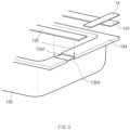
- FIG. 5 is a detailed assembled view illustrating a state in which the metal foil layer 1354 and a negative electrode lead 122 are connected to each other according to an embodiment of the present invention.
- the metal foil layer 1354 is connected to the negative electrode 102 of the electrode assembly 10, particularly, the negative electrode lead 122 extending from the negative electrode 102.
- the surface protection layer 1352, the sealant layer 1353, and the gas barrier layer 1351 are removed from the specific area 1341 of the sealing part 134 formed on the edge of the pouch 13, which corresponds to an area on which the negative electrode lead 122 exists.
- the metal foil layer 1354 may be exposed to the outside.
- the negative electrode lead 122 contacts the metal foil layer 1354 exposed through the specific area 1341 in the pouch 13.
- the negative electrode lead 122 and the metal foil layer 1354 may be easily welded to each other through laser welding or ultrasonic welding and then be connected to each other.
- the metal foil layer 1354 and the negative electrode lead 122 are exposed to the outside as well as the inside on the specific area 1341.
- the surface protection layer 1352 is removed also from the specific area 1341.
- the connection between the metal foil layer 1354 and the negative electrode lead 122 is not interrupted.
- the negative electrode lead 122 and the metal foil layer 1354 are welded to each other without removing the surface protection layer 1352, only the sealant layer 1353 and the gas barrier layer 1351 may be removed from the specific area 1341, and the surface protection layer 1352 may not be removed.
- FIG. 5 illustrates a state in which the metal foil layer 1354 is exposed on only the sealing part 134 of the lower pouch 132 and connected to the negative electrode lead 122.
- the upper pouch 131 and the lower pouch 132 may be separated from each other so as to be separately manufactured.
- a portion of the metal foil layer 1354 may be cut while being folded.
- the metal foil layer 1354 of the upper pouch 131 and the metal foil layer 1354 of the lower pouch 132 may be electrically disconnected from each other.
- the negative electrode lead 122 is connected to only the metal foil layer 1354 of the lower pouch 132, the risk of the explosion may not be reduced when the nail 2 passes from a side of the upper pouch 131.
- the surface protection layer 1352, the sealant layer 1353, and the gas barrier layer 1351 may be removed from the area corresponding to the negative electrode lead 122 in the upper pouch 131 as well as the lower pouch 132 to expose the metal foil layer 1354.
- the negative electrode lead 122 is connected to the metal foil layer 1354 on each of the top and bottom surface thereof.
- a stepped portion may be formed on the specific area 1341 of the sealing part 134 of the pouch 13.
- the insulation part 14 surrounds the periphery of the positive electrode lead 121, whereas the insulation part 14 does not surround the periphery of the negative electrode lead 122.
- the negative electrode lead 122 is directly welded and connected to the metal foil layer 1354, a deviation in sealing thickness between the positive electrode lead 121 and the negative electrode lead 122 may not be large.
- the negative electrode lead 122 may have a thickness greater than that of the positive electrode lead 121, or a protrusion protruding from the negative electrode lead 122 toward the metal foil layer 1354 may be formed to reduce the deviation.
- FIG. 6 is a schematic view illustrating a state in which the nail 2 approaches the secondary battery 1 according to an embodiment
- FIG. 7 is a schematic view illustrating a state in which the nail 2 passes through the secondary battery 1 according to an embodiment of the prevent invention.
- the metal foil layer 1354 may have a negative polarity.
- the metal foil layer 1354 and the positive electrode active material 1012 may contact each other first. That is, before the most dangerous short circuit between the positive electrode collector 1011 and the negative electrode active material 1022 occurs, the short circuit between the metal foil layer 1354 and the positive electrode active material 1012 may be induced first. Therefore, the heat generation rate may be reduced.
- the metal foil layer 1354 may be laminated all over the inside of the pouch 13. That is, the metal foil layer 1354 may have a relatively large surface area when compared to the electrode assembly 10 and be disposed at the outside. Thus, even though the metal foil layer 1354 and the positive electrode active material 1012 are short-circuited to raise a temperature of the metal foil layer 1354, heat may be easily released to the outside when compared to the short circuit that occurs within the electrode assembly 10 to raise a temperature. Therefore, the risk of the explosion may be reduced.
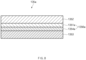
- FIG. 8 is a partial cross-sectional view of the pouch 13 according to an embodiment of the present invention.
- the metal foil layer 1354 and the gas barrier layer 1351 which are provided in the pouch film 135, may be separate layers. Also, to prevent the gas barrier layer 1351 from having the polarity, the insulation layer 1355, which insulates the metal foil layer 1354 from the gas barrier layer 1351, may be further laminated between the metal foil layer 1354 and the gas barrier layer 1351. Thus, the metal foil layer 1354 and the gas barrier layer 1351 may not be connected to each other.
- the first metal forming the gas barrier layer 1351 may be aluminum as described above.
- the aluminum has advantages that it is light in weight, has strong corrosion resistance against water or oxygen, and has weak salt resistance against salt and the like. Thus, if the sealant layer 1353 is partially broken due to deterioration of the pouch 13 or initial failure of the product, aluminum may contact the electrolyte within the pouch 13 and thus be corroded.
- a gas barrier layer 1351a and a metal foil layer 1354a which are provided in a pouch film 135a, may be clad-rolled to be mechanically bonded to each other in a state of overlapping each other, thereby forming a clad-rolled layer 1356a.
- the clad is a metal rolling method in which various metals are bonded to each other to take only advantages of each metal.
- a first metal of the gas barrier layer 1351a is disposed above a second metal of the metal foil layer 1354a.
- the second metal may be copper.
- the copper is stronger in salt water resistance than aluminum.
Landscapes
- Chemical & Material Sciences (AREA)
- Chemical Kinetics & Catalysis (AREA)
- Electrochemistry (AREA)
- General Chemical & Material Sciences (AREA)
- Inorganic Chemistry (AREA)
- Sealing Battery Cases Or Jackets (AREA)
- Connection Of Batteries Or Terminals (AREA)
- Battery Mounting, Suspending (AREA)
Claims (11)
- Batterie secondaire de type poche comprenant :un assemblage d'électrodes (10) dans lequel une électrode positive (101), un séparateur (103) et une électrode négative (102) sont stratifiés ; etune poche comprenant une poche supérieure (131) et une poche inférieure (132) etconfigurée pour loger l'assemblage d'électrodes (10),dans laquelle la poche comprend :une couche de protection de surface (1352) constituée d'un premier polymère et formée au niveau d'une couche la plus à l'extérieur ;une couche d'étanchéité (1353) constituée d'un deuxième polymère et formée au niveau d'une couche la plus à l'intérieur ;une couche barrière aux gaz (1351) constituée d'un premier métal et stratifiée entre la couche de protection de surface et la couche d'étanchéité ; etune couche de feuille métallique (1354) constituée d'un deuxième métal, stratifiée entre la couche de protection de surface et la couche d'étanchéité, et connectée à l'électrode négative de l'ensemble d'électrodes,dans laquelle la couche de feuille métallique (1354) est connectée à un fil d'électrode négative s'étendant à partir de l'électrode négative de façon à être connectée à l'électrode négative, etdes parties de la couche de protection de surface, de la couche d'étanchéité et de la couche barrière aux gaz sont retirées d'une zone spécifique correspondant à une zone sur laquelle le fil d'électrode négative existe dans la poche supérieure (131) et la poche inférieure (132).
- Batterie secondaire de type poche selon la revendication 1, dans laquelle le fil d'électrode négative (122) est configuré pour être soudé et connecté à la couche de feuille métallique (1354) exposée à travers la zone spécifique.
- Batterie secondaire de type poche selon la revendication 1, comprenant en outre une couche d'isolation (1355), qui isole la couche barrière aux gaz (1351) de la couche de feuille métallique (1354), entre la couche barrière aux gaz (1351) et la couche de feuille métallique (1354).
- Batterie secondaire de type poche selon la revendication 1, dans laquelle la couche de feuille métallique (1354) est configurée pour être laminée et plaquée conjointement avec la couche barrière aux gaz (1351).
- Batterie secondaire de type poche selon la revendication 1, dans laquelle le premier polymère comprend du polyéthylène téréphtalate (PET).
- Batterie secondaire de type poche selon la revendication 1, dans laquelle le premier métal comprend de l'aluminium.
- Batterie secondaire de type poche selon la revendication 1, dans laquelle le deuxième métal comprend le même type de métal que le métal contenu dans un collecteur d'électrode négative (1021) de l'électrode négative.
- Batterie secondaire de type poche selon la revendication 7, dans laquelle le deuxième métal comprend du cuivre.
- Batterie secondaire de type poche selon la revendication 1, dans laquelle le deuxième polymère comprend du polypropylène.
- Poche pour une batterie secondaire de type poche, qui est destinée à loger un assemblage d'électrodes dans lequel une électrode positive (101), un séparateur (103) et une électrode négative (102) sont stratifiés, la poche comprenant une poche supérieure (131) et une poche inférieure (132) et comprenant :une couche de protection de surface (1352) constituée d'un premier polymère et formée au niveau d'une couche la plus à l'extérieur ;une couche d'étanchéité (1353) constituée d'un deuxième polymère et formée au niveau d'une couche la plus à l'intérieur ;une couche barrière aux gaz (1351) constituée d'un premier métal et stratifiée entre la couche de protection de surface et la couche d'étanchéité ; etune couche de feuille métallique (1354) constituée d'un deuxième métal, stratifiée entre la couche de protection de surface et la couche d'étanchéité, et connectée à l'électrode négative de l'assemblage d'électrodes,dans laquelle des parties de la couche de protection de surface, de la couche d'étanchéité et de la couche barrière aux gaz sont retirées d'une zone spécifique pour exposer la couche de feuille métallique à l'extérieur ; etla zone spécifique correspond à une zone sur laquelle un fil d'électrode négative (122) s'étendant à partir de l'électrode négative existe dans la poche supérieure (131) et la poche inférieure (132) lorsque l'ensemble d'électrodes est logé.
- Poche selon la revendication 10, comprenant en outre une couche d'isolation (1355), qui isole la couche barrière aux gaz (1351) de la couche de feuille métallique (1354), entre la couche barrière aux gaz et la couche de feuille métallique.
Applications Claiming Priority (2)
| Application Number | Priority Date | Filing Date | Title |
|---|---|---|---|
| KR1020180101950A KR102325036B1 (ko) | 2018-08-29 | 2018-08-29 | 파우치형 이차 전지 및 이차 전지용 파우치 |
| PCT/KR2019/008076 WO2020045814A1 (fr) | 2018-08-29 | 2019-07-02 | Batterie secondaire de type poche et poche pour batterie secondaire |
Publications (3)
| Publication Number | Publication Date |
|---|---|
| EP3671886A1 EP3671886A1 (fr) | 2020-06-24 |
| EP3671886A4 EP3671886A4 (fr) | 2020-12-23 |
| EP3671886B1 true EP3671886B1 (fr) | 2024-05-15 |
Family
ID=69644536
Family Applications (1)
| Application Number | Title | Priority Date | Filing Date |
|---|---|---|---|
| EP19854713.5A Active EP3671886B1 (fr) | 2018-08-29 | 2019-07-02 | Batterie secondaire de type poche et poche pour batterie secondaire |
Country Status (10)
| Country | Link |
|---|---|
| US (1) | US11682809B2 (fr) |
| EP (1) | EP3671886B1 (fr) |
| JP (1) | JP7049550B2 (fr) |
| KR (1) | KR102325036B1 (fr) |
| CN (1) | CN111108622B (fr) |
| ES (1) | ES2981317T3 (fr) |
| HU (1) | HUE066960T2 (fr) |
| PL (1) | PL3671886T3 (fr) |
| TW (2) | TWI862504B (fr) |
| WO (1) | WO2020045814A1 (fr) |
Families Citing this family (13)
| Publication number | Priority date | Publication date | Assignee | Title |
|---|---|---|---|---|
| HUE070118T2 (hu) * | 2020-04-14 | 2025-05-28 | Lg Energy Solution Ltd | Tasak típusú teleptok és tasak típusú újratölthetõ telep |
| CN215955369U (zh) * | 2020-06-09 | 2022-03-04 | 株式会社Lg化学 | 袋膜、袋型电池壳体、和袋型二次电池 |
| EP4199201A4 (fr) * | 2020-08-19 | 2024-09-04 | LG Energy Solution, Ltd. | Batterie secondaire de type poche et son procédé de fabrication |
| KR102757256B1 (ko) * | 2020-11-10 | 2025-01-20 | 주식회사 엘지에너지솔루션 | 레이저 용접법으로 회로기판과 전극 리드를 직접 접합한 배터리 팩 |
| CN112864498A (zh) * | 2021-03-19 | 2021-05-28 | 惠州锂威新能源科技有限公司 | 一种多极耳电芯及其制备方法 |
| CN115870948B (zh) * | 2021-08-10 | 2025-11-07 | 华为技术有限公司 | 柔性驱动单元和柔性驱动器 |
| JP7812205B2 (ja) * | 2021-08-16 | 2026-02-09 | 株式会社Dnp高機能マテリアル彦根 | 全固体電池用外装材および全固体電池 |
| WO2023017683A1 (fr) * | 2021-08-11 | 2023-02-16 | 昭和電工パッケージング株式会社 | Matériau d'emballage externe pour des batteries tout solides, et batterie tout solide |
| JP7747463B2 (ja) * | 2021-08-16 | 2025-10-01 | 株式会社Dnp高機能マテリアル彦根 | 全固体電池用外装材および全固体電池 |
| CN113588668B (zh) * | 2021-09-01 | 2024-07-05 | 广东奥普特科技股份有限公司 | 一种基于机器视觉的极耳漏金属检测方法及检测系统 |
| WO2023039706A1 (fr) * | 2021-09-14 | 2023-03-23 | 宁德新能源科技有限公司 | Élément de batterie, batterie et dispositif électrique |
| DE202023003118U1 (de) * | 2022-10-14 | 2026-02-24 | Lg Energy Solution, Ltd. | Sekundärbatterie |
| WO2025105921A1 (fr) * | 2023-11-14 | 2025-05-22 | 주식회사 엘지에너지솔루션 | Stratifié de film de poche, son procédé de fabrication et batterie secondaire de type poche |
Family Cites Families (34)
| Publication number | Priority date | Publication date | Assignee | Title |
|---|---|---|---|---|
| US6632538B1 (en) * | 1998-02-05 | 2003-10-14 | Dai Nippon Printing Co., Ltd. | Sheet for cell and cell device |
| JP2000251857A (ja) | 1999-03-02 | 2000-09-14 | Mitsubishi Chemicals Corp | 非水系二次電池 |
| JP2001297795A (ja) * | 2000-04-11 | 2001-10-26 | Mitsubishi Chemicals Corp | 電 池 |
| KR100544119B1 (ko) * | 2003-06-24 | 2006-01-23 | 삼성에스디아이 주식회사 | 파우치형 리튬 이차 전지 |
| JP4949022B2 (ja) * | 2003-07-11 | 2012-06-06 | エルジー・ケム・リミテッド | 二次電池及び電池包装材 |
| JP2005183051A (ja) | 2003-12-16 | 2005-07-07 | Mitsubishi Electric Corp | 電池 |
| US8722235B2 (en) | 2004-04-21 | 2014-05-13 | Blue Spark Technologies, Inc. | Thin printable flexible electrochemical cell and method of making the same |
| KR101089161B1 (ko) | 2007-12-17 | 2011-12-02 | 주식회사 엘지화학 | 파우치형 이차전지 |
| KR101405621B1 (ko) | 2008-01-08 | 2014-06-10 | 주식회사 엘지화학 | 이차전지용 파우치 포장재 및 파우치형 이차전지 |
| KR101065379B1 (ko) * | 2009-07-10 | 2011-09-16 | 삼성에스디아이 주식회사 | 전지 모듈 |
| KR101156240B1 (ko) * | 2009-12-08 | 2012-06-13 | 삼성에스디아이 주식회사 | 이차전지 |
| KR101183557B1 (ko) | 2009-12-21 | 2012-09-17 | 주식회사 이아이지 | 난연 물질 및 내열 물질이 포함되어 안전성이 향상된 전기 화학 소자용 외장재 및 상기 외장재를 구비한 전기 화학 소자 |
| US8518569B2 (en) | 2010-03-01 | 2013-08-27 | Apple Inc. | Integrated frame battery cell |
| US8551633B2 (en) | 2011-08-18 | 2013-10-08 | Samsung Sdi Co., Ltd. | Secondary battery |
| JP2013222687A (ja) | 2012-04-19 | 2013-10-28 | Gs Yuasa Corp | 電池 |
| JP2014086361A (ja) | 2012-10-26 | 2014-05-12 | Toray Advanced Film Co Ltd | 二次電池外装材用アルミニウム箔積層シートおよび二次電池外装材 |
| KR20140059650A (ko) * | 2012-11-08 | 2014-05-16 | 주식회사 엘지화학 | 안전성이 향상된 이차전지용 파우치 외장재 및 이를 포함하는 이차전지 |
| KR20140147041A (ko) * | 2013-06-18 | 2014-12-29 | 주식회사 엘지화학 | 셀 포장재료 및 그 제조방법 |
| KR20140148121A (ko) * | 2013-06-21 | 2014-12-31 | 주식회사 엘지화학 | 파우치 외장재 및 이를 포함하는 이차 전지 |
| JP6492402B2 (ja) | 2014-02-18 | 2019-04-03 | 凸版印刷株式会社 | 蓄電デバイス用外装材 |
| WO2015163025A1 (fr) * | 2014-04-25 | 2015-10-29 | Necエナジーデバイス株式会社 | Batterie secondaire |
| JP6629514B2 (ja) * | 2014-05-08 | 2020-01-15 | 昭和電工パッケージング株式会社 | ラミネート外装材の製造方法 |
| JP6426934B2 (ja) * | 2014-07-29 | 2018-11-21 | 昭和電工パッケージング株式会社 | 電気化学デバイスおよびその製造方法 |
| KR101744120B1 (ko) | 2014-08-11 | 2017-06-07 | 주식회사 엘지화학 | 침상 관통 테스트 안전성이 향상된 파우치형 이차전지 |
| JP6412388B2 (ja) | 2014-09-30 | 2018-10-24 | 昭和電工パッケージング株式会社 | 成形用包装材 |
| KR101883536B1 (ko) | 2015-04-29 | 2018-07-30 | 주식회사 엘지화학 | 파우치형 이차전지 및 그 제조방법 |
| JP2017041390A (ja) | 2015-08-21 | 2017-02-23 | 昭和電工パッケージング株式会社 | ラミネート外装材 |
| WO2017110062A1 (fr) | 2015-12-25 | 2017-06-29 | パナソニックIpマネジメント株式会社 | Matière de film pour extérieur de batterie, et batterie souple la comprenant |
| KR102065128B1 (ko) | 2016-03-29 | 2020-01-10 | 주식회사 엘지화학 | 파우치형 이차 전지 |
| CN105742529A (zh) * | 2016-04-14 | 2016-07-06 | 东莞新能源科技有限公司 | 一种锂离子电池包装用复合膜,其封装外壳及制备方法 |
| KR101966359B1 (ko) * | 2016-09-13 | 2019-04-08 | 주식회사 엘지화학 | 2차 전지 |
| KR101905991B1 (ko) * | 2016-10-26 | 2018-10-08 | 현대자동차주식회사 | 관통 안정성이 향상된 파우치형 배터리 셀 |
| KR102334019B1 (ko) | 2017-10-17 | 2021-12-02 | 주식회사 엘지에너지솔루션 | 다종 금속 차단층을 포함하는 전지케이스 및 이를 포함하고 있는 전지셀 |
| CN207381438U (zh) | 2017-10-30 | 2018-05-18 | 东莞市卓越新材料科技有限公司 | 耐腐蚀的铜塑膜 |
-
2018
- 2018-08-29 KR KR1020180101950A patent/KR102325036B1/ko active Active
-
2019
- 2019-07-02 HU HUE19854713A patent/HUE066960T2/hu unknown
- 2019-07-02 EP EP19854713.5A patent/EP3671886B1/fr active Active
- 2019-07-02 JP JP2020519971A patent/JP7049550B2/ja active Active
- 2019-07-02 PL PL19854713.5T patent/PL3671886T3/pl unknown
- 2019-07-02 WO PCT/KR2019/008076 patent/WO2020045814A1/fr not_active Ceased
- 2019-07-02 US US16/755,796 patent/US11682809B2/en active Active
- 2019-07-02 ES ES19854713T patent/ES2981317T3/es active Active
- 2019-07-02 CN CN201980004498.XA patent/CN111108622B/zh active Active
- 2019-07-11 TW TW108124446A patent/TWI862504B/zh active
- 2019-07-11 TW TW112121451A patent/TWI863339B/zh active
Also Published As
| Publication number | Publication date |
|---|---|
| TW202339337A (zh) | 2023-10-01 |
| TW202010166A (zh) | 2020-03-01 |
| PL3671886T3 (pl) | 2024-08-05 |
| US20210083233A1 (en) | 2021-03-18 |
| JP2020537291A (ja) | 2020-12-17 |
| WO2020045814A1 (fr) | 2020-03-05 |
| ES2981317T3 (es) | 2024-10-08 |
| EP3671886A4 (fr) | 2020-12-23 |
| KR20200025101A (ko) | 2020-03-10 |
| US11682809B2 (en) | 2023-06-20 |
| CN111108622A (zh) | 2020-05-05 |
| JP7049550B2 (ja) | 2022-04-07 |
| TWI862504B (zh) | 2024-11-21 |
| EP3671886A1 (fr) | 2020-06-24 |
| TWI863339B (zh) | 2024-11-21 |
| CN111108622B (zh) | 2022-11-11 |
| HUE066960T2 (hu) | 2024-09-28 |
| KR102325036B1 (ko) | 2021-11-11 |
Similar Documents
| Publication | Publication Date | Title |
|---|---|---|
| EP3671886B1 (fr) | Batterie secondaire de type poche et poche pour batterie secondaire | |
| US11289782B2 (en) | Secondary battery | |
| US12206120B2 (en) | Battery case for secondary battery and method for manufacturing pouch type secondary battery | |
| KR20230047904A (ko) | 파우치 필름 적층체 및 이차 전지 | |
| KR101375398B1 (ko) | 전기절연성과 수분침투성이 개선된 파우치형 이차전지 | |
| EP4303989A2 (fr) | Compartiment de batterie pour batterie secondaire et procédé de fabrication de partie de décharge de gaz | |
| KR101984265B1 (ko) | 파우치형 이차전지 및 그 제조방법 | |
| KR20220040347A (ko) | 사이드 폴딩 장치 및 방법 | |
| US20200220134A1 (en) | Secondary battery | |
| EP3758133B1 (fr) | Poche pour batterie secondaire et batterie secondaire de type poche | |
| US20230105613A1 (en) | Apparatus and Method for Folding Side | |
| JP2023502614A (ja) | 二次電池およびシールブロック | |
| KR20100016719A (ko) | 전기절연성과 수분침투성이 개선된 파우치형 이차전지 | |
| KR102876527B1 (ko) | 파우치형 이차 전지 | |
| KR20170014293A (ko) | 이차 전지 모듈 및 그 제조 방법과 이를 구비하는 전지 팩 | |
| KR20250159609A (ko) | 파우치형 이차 전지 | |
| KR101785573B1 (ko) | 이차 전지 모듈 및 그 제조 방법과 이를 구비하는 전지 팩 | |
| US20240106036A1 (en) | Pouch Film Laminate and Secondary Battery | |
| KR102475343B1 (ko) | 이차 전지 및 그의 제조 방법 | |
| KR20230063178A (ko) | 안전성이 향상된 파우치형 전지셀 | |
| KR102373583B1 (ko) | 파우치형 이차전지 | |
| US12580252B2 (en) | Pouch-type battery case and pouch-type secondary battery | |
| JP2025539911A (ja) | パウチフィルム積層体及び二次電池 |
Legal Events
| Date | Code | Title | Description |
|---|---|---|---|
| STAA | Information on the status of an ep patent application or granted ep patent |
Free format text: STATUS: THE INTERNATIONAL PUBLICATION HAS BEEN MADE |
|
| PUAI | Public reference made under article 153(3) epc to a published international application that has entered the european phase |
Free format text: ORIGINAL CODE: 0009012 |
|
| STAA | Information on the status of an ep patent application or granted ep patent |
Free format text: STATUS: REQUEST FOR EXAMINATION WAS MADE |
|
| 17P | Request for examination filed |
Effective date: 20200319 |
|
| AK | Designated contracting states |
Kind code of ref document: A1 Designated state(s): AL AT BE BG CH CY CZ DE DK EE ES FI FR GB GR HR HU IE IS IT LI LT LU LV MC MK MT NL NO PL PT RO RS SE SI SK SM TR |
|
| AX | Request for extension of the european patent |
Extension state: BA ME |
|
| A4 | Supplementary search report drawn up and despatched |
Effective date: 20201120 |
|
| RIC1 | Information provided on ipc code assigned before grant |
Ipc: H01M 2/30 20060101ALI20201116BHEP Ipc: B32B 15/09 20060101ALI20201116BHEP Ipc: B32B 15/20 20060101ALI20201116BHEP Ipc: H01M 2/26 20060101ALI20201116BHEP Ipc: H01M 2/02 20060101AFI20201116BHEP |
|
| DAV | Request for validation of the european patent (deleted) | ||
| DAX | Request for extension of the european patent (deleted) | ||
| RAP1 | Party data changed (applicant data changed or rights of an application transferred) |
Owner name: LG ENERGY SOLUTION LTD. |
|
| RAP3 | Party data changed (applicant data changed or rights of an application transferred) |
Owner name: LG ENERGY SOLUTION, LTD. |
|
| REG | Reference to a national code |
Ref country code: DE Ref legal event code: R079 Free format text: PREVIOUS MAIN CLASS: H01M0002020000 Ipc: H01M0050105000 Ref country code: DE Ref legal event code: R079 Ref document number: 602019052382 Country of ref document: DE Free format text: PREVIOUS MAIN CLASS: H01M0002020000 Ipc: H01M0050105000 |
|
| RIC1 | Information provided on ipc code assigned before grant |
Ipc: H01M 50/562 20210101ALI20230824BHEP Ipc: H01M 50/557 20210101ALI20230824BHEP Ipc: H01M 50/55 20210101ALI20230824BHEP Ipc: H01M 50/536 20210101ALI20230824BHEP Ipc: B32B 15/20 20060101ALI20230824BHEP Ipc: B32B 15/09 20060101ALI20230824BHEP Ipc: H01M 50/178 20210101ALI20230824BHEP Ipc: H01M 50/14 20210101ALI20230824BHEP Ipc: H01M 50/128 20210101ALI20230824BHEP Ipc: H01M 50/129 20210101ALI20230824BHEP Ipc: H01M 50/124 20210101ALI20230824BHEP Ipc: H01M 50/121 20210101ALI20230824BHEP Ipc: H01M 50/119 20210101ALI20230824BHEP Ipc: H01M 50/105 20210101AFI20230824BHEP |
|
| GRAP | Despatch of communication of intention to grant a patent |
Free format text: ORIGINAL CODE: EPIDOSNIGR1 |
|
| STAA | Information on the status of an ep patent application or granted ep patent |
Free format text: STATUS: GRANT OF PATENT IS INTENDED |
|
| INTG | Intention to grant announced |
Effective date: 20231019 |
|
| GRAJ | Information related to disapproval of communication of intention to grant by the applicant or resumption of examination proceedings by the epo deleted |
Free format text: ORIGINAL CODE: EPIDOSDIGR1 |
|
| STAA | Information on the status of an ep patent application or granted ep patent |
Free format text: STATUS: REQUEST FOR EXAMINATION WAS MADE |
|
| P01 | Opt-out of the competence of the unified patent court (upc) registered |
Effective date: 20231030 |
|
| INTC | Intention to grant announced (deleted) | ||
| GRAP | Despatch of communication of intention to grant a patent |
Free format text: ORIGINAL CODE: EPIDOSNIGR1 |
|
| STAA | Information on the status of an ep patent application or granted ep patent |
Free format text: STATUS: GRANT OF PATENT IS INTENDED |
|
| INTG | Intention to grant announced |
Effective date: 20240117 |
|
| GRAS | Grant fee paid |
Free format text: ORIGINAL CODE: EPIDOSNIGR3 |
|
| GRAA | (expected) grant |
Free format text: ORIGINAL CODE: 0009210 |
|
| STAA | Information on the status of an ep patent application or granted ep patent |
Free format text: STATUS: THE PATENT HAS BEEN GRANTED |
|
| AK | Designated contracting states |
Kind code of ref document: B1 Designated state(s): AL AT BE BG CH CY CZ DE DK EE ES FI FR GB GR HR HU IE IS IT LI LT LU LV MC MK MT NL NO PL PT RO RS SE SI SK SM TR |
|
| REG | Reference to a national code |
Ref country code: CH Ref legal event code: EP |
|
| REG | Reference to a national code |
Ref country code: DE Ref legal event code: R096 Ref document number: 602019052382 Country of ref document: DE |
|
| REG | Reference to a national code |
Ref country code: IE Ref legal event code: FG4D |
|
| REG | Reference to a national code |
Ref country code: SE Ref legal event code: TRGR |
|
| REG | Reference to a national code |
Ref country code: LT Ref legal event code: MG9D |
|
| REG | Reference to a national code |
Ref country code: NL Ref legal event code: MP Effective date: 20240515 |
|
| REG | Reference to a national code |
Ref country code: HU Ref legal event code: AG4A Ref document number: E066960 Country of ref document: HU |
|
| PG25 | Lapsed in a contracting state [announced via postgrant information from national office to epo] |
Ref country code: IS Free format text: LAPSE BECAUSE OF FAILURE TO SUBMIT A TRANSLATION OF THE DESCRIPTION OR TO PAY THE FEE WITHIN THE PRESCRIBED TIME-LIMIT Effective date: 20240915 |
|
| PG25 | Lapsed in a contracting state [announced via postgrant information from national office to epo] |
Ref country code: BG Free format text: LAPSE BECAUSE OF FAILURE TO SUBMIT A TRANSLATION OF THE DESCRIPTION OR TO PAY THE FEE WITHIN THE PRESCRIBED TIME-LIMIT Effective date: 20240515 |
|
| REG | Reference to a national code |
Ref country code: ES Ref legal event code: FG2A Ref document number: 2981317 Country of ref document: ES Kind code of ref document: T3 Effective date: 20241008 |
|
| PG25 | Lapsed in a contracting state [announced via postgrant information from national office to epo] |
Ref country code: FI Free format text: LAPSE BECAUSE OF FAILURE TO SUBMIT A TRANSLATION OF THE DESCRIPTION OR TO PAY THE FEE WITHIN THE PRESCRIBED TIME-LIMIT Effective date: 20240515 Ref country code: HR Free format text: LAPSE BECAUSE OF FAILURE TO SUBMIT A TRANSLATION OF THE DESCRIPTION OR TO PAY THE FEE WITHIN THE PRESCRIBED TIME-LIMIT Effective date: 20240515 |
|
| PG25 | Lapsed in a contracting state [announced via postgrant information from national office to epo] |
Ref country code: GR Free format text: LAPSE BECAUSE OF FAILURE TO SUBMIT A TRANSLATION OF THE DESCRIPTION OR TO PAY THE FEE WITHIN THE PRESCRIBED TIME-LIMIT Effective date: 20240816 |
|
| PG25 | Lapsed in a contracting state [announced via postgrant information from national office to epo] |
Ref country code: PT Free format text: LAPSE BECAUSE OF FAILURE TO SUBMIT A TRANSLATION OF THE DESCRIPTION OR TO PAY THE FEE WITHIN THE PRESCRIBED TIME-LIMIT Effective date: 20240916 |
|
| REG | Reference to a national code |
Ref country code: AT Ref legal event code: MK05 Ref document number: 1687648 Country of ref document: AT Kind code of ref document: T Effective date: 20240515 |
|
| PG25 | Lapsed in a contracting state [announced via postgrant information from national office to epo] |
Ref country code: NL Free format text: LAPSE BECAUSE OF FAILURE TO SUBMIT A TRANSLATION OF THE DESCRIPTION OR TO PAY THE FEE WITHIN THE PRESCRIBED TIME-LIMIT Effective date: 20240515 |
|
| PG25 | Lapsed in a contracting state [announced via postgrant information from national office to epo] |
Ref country code: AT Free format text: LAPSE BECAUSE OF FAILURE TO SUBMIT A TRANSLATION OF THE DESCRIPTION OR TO PAY THE FEE WITHIN THE PRESCRIBED TIME-LIMIT Effective date: 20240515 |
|
| PG25 | Lapsed in a contracting state [announced via postgrant information from national office to epo] |
Ref country code: LV Free format text: LAPSE BECAUSE OF FAILURE TO SUBMIT A TRANSLATION OF THE DESCRIPTION OR TO PAY THE FEE WITHIN THE PRESCRIBED TIME-LIMIT Effective date: 20240515 |
|
| PG25 | Lapsed in a contracting state [announced via postgrant information from national office to epo] |
Ref country code: PT Free format text: LAPSE BECAUSE OF FAILURE TO SUBMIT A TRANSLATION OF THE DESCRIPTION OR TO PAY THE FEE WITHIN THE PRESCRIBED TIME-LIMIT Effective date: 20240916 Ref country code: NO Free format text: LAPSE BECAUSE OF FAILURE TO SUBMIT A TRANSLATION OF THE DESCRIPTION OR TO PAY THE FEE WITHIN THE PRESCRIBED TIME-LIMIT Effective date: 20240815 Ref country code: NL Free format text: LAPSE BECAUSE OF FAILURE TO SUBMIT A TRANSLATION OF THE DESCRIPTION OR TO PAY THE FEE WITHIN THE PRESCRIBED TIME-LIMIT Effective date: 20240515 Ref country code: LV Free format text: LAPSE BECAUSE OF FAILURE TO SUBMIT A TRANSLATION OF THE DESCRIPTION OR TO PAY THE FEE WITHIN THE PRESCRIBED TIME-LIMIT Effective date: 20240515 Ref country code: IS Free format text: LAPSE BECAUSE OF FAILURE TO SUBMIT A TRANSLATION OF THE DESCRIPTION OR TO PAY THE FEE WITHIN THE PRESCRIBED TIME-LIMIT Effective date: 20240915 Ref country code: HR Free format text: LAPSE BECAUSE OF FAILURE TO SUBMIT A TRANSLATION OF THE DESCRIPTION OR TO PAY THE FEE WITHIN THE PRESCRIBED TIME-LIMIT Effective date: 20240515 Ref country code: GR Free format text: LAPSE BECAUSE OF FAILURE TO SUBMIT A TRANSLATION OF THE DESCRIPTION OR TO PAY THE FEE WITHIN THE PRESCRIBED TIME-LIMIT Effective date: 20240816 Ref country code: FI Free format text: LAPSE BECAUSE OF FAILURE TO SUBMIT A TRANSLATION OF THE DESCRIPTION OR TO PAY THE FEE WITHIN THE PRESCRIBED TIME-LIMIT Effective date: 20240515 Ref country code: BG Free format text: LAPSE BECAUSE OF FAILURE TO SUBMIT A TRANSLATION OF THE DESCRIPTION OR TO PAY THE FEE WITHIN THE PRESCRIBED TIME-LIMIT Effective date: 20240515 Ref country code: AT Free format text: LAPSE BECAUSE OF FAILURE TO SUBMIT A TRANSLATION OF THE DESCRIPTION OR TO PAY THE FEE WITHIN THE PRESCRIBED TIME-LIMIT Effective date: 20240515 Ref country code: RS Free format text: LAPSE BECAUSE OF FAILURE TO SUBMIT A TRANSLATION OF THE DESCRIPTION OR TO PAY THE FEE WITHIN THE PRESCRIBED TIME-LIMIT Effective date: 20240815 |
|
| PG25 | Lapsed in a contracting state [announced via postgrant information from national office to epo] |
Ref country code: DK Free format text: LAPSE BECAUSE OF FAILURE TO SUBMIT A TRANSLATION OF THE DESCRIPTION OR TO PAY THE FEE WITHIN THE PRESCRIBED TIME-LIMIT Effective date: 20240515 |
|
| PG25 | Lapsed in a contracting state [announced via postgrant information from national office to epo] |
Ref country code: EE Free format text: LAPSE BECAUSE OF FAILURE TO SUBMIT A TRANSLATION OF THE DESCRIPTION OR TO PAY THE FEE WITHIN THE PRESCRIBED TIME-LIMIT Effective date: 20240515 |
|
| PG25 | Lapsed in a contracting state [announced via postgrant information from national office to epo] |
Ref country code: CZ Free format text: LAPSE BECAUSE OF FAILURE TO SUBMIT A TRANSLATION OF THE DESCRIPTION OR TO PAY THE FEE WITHIN THE PRESCRIBED TIME-LIMIT Effective date: 20240515 |
|
| PG25 | Lapsed in a contracting state [announced via postgrant information from national office to epo] |
Ref country code: SK Free format text: LAPSE BECAUSE OF FAILURE TO SUBMIT A TRANSLATION OF THE DESCRIPTION OR TO PAY THE FEE WITHIN THE PRESCRIBED TIME-LIMIT Effective date: 20240515 Ref country code: RO Free format text: LAPSE BECAUSE OF FAILURE TO SUBMIT A TRANSLATION OF THE DESCRIPTION OR TO PAY THE FEE WITHIN THE PRESCRIBED TIME-LIMIT Effective date: 20240515 |
|
| PG25 | Lapsed in a contracting state [announced via postgrant information from national office to epo] |
Ref country code: SM Free format text: LAPSE BECAUSE OF FAILURE TO SUBMIT A TRANSLATION OF THE DESCRIPTION OR TO PAY THE FEE WITHIN THE PRESCRIBED TIME-LIMIT Effective date: 20240515 |
|
| PG25 | Lapsed in a contracting state [announced via postgrant information from national office to epo] |
Ref country code: SM Free format text: LAPSE BECAUSE OF FAILURE TO SUBMIT A TRANSLATION OF THE DESCRIPTION OR TO PAY THE FEE WITHIN THE PRESCRIBED TIME-LIMIT Effective date: 20240515 Ref country code: SK Free format text: LAPSE BECAUSE OF FAILURE TO SUBMIT A TRANSLATION OF THE DESCRIPTION OR TO PAY THE FEE WITHIN THE PRESCRIBED TIME-LIMIT Effective date: 20240515 Ref country code: RO Free format text: LAPSE BECAUSE OF FAILURE TO SUBMIT A TRANSLATION OF THE DESCRIPTION OR TO PAY THE FEE WITHIN THE PRESCRIBED TIME-LIMIT Effective date: 20240515 Ref country code: EE Free format text: LAPSE BECAUSE OF FAILURE TO SUBMIT A TRANSLATION OF THE DESCRIPTION OR TO PAY THE FEE WITHIN THE PRESCRIBED TIME-LIMIT Effective date: 20240515 Ref country code: DK Free format text: LAPSE BECAUSE OF FAILURE TO SUBMIT A TRANSLATION OF THE DESCRIPTION OR TO PAY THE FEE WITHIN THE PRESCRIBED TIME-LIMIT Effective date: 20240515 Ref country code: CZ Free format text: LAPSE BECAUSE OF FAILURE TO SUBMIT A TRANSLATION OF THE DESCRIPTION OR TO PAY THE FEE WITHIN THE PRESCRIBED TIME-LIMIT Effective date: 20240515 |
|
| PG25 | Lapsed in a contracting state [announced via postgrant information from national office to epo] |
Ref country code: MC Free format text: LAPSE BECAUSE OF FAILURE TO SUBMIT A TRANSLATION OF THE DESCRIPTION OR TO PAY THE FEE WITHIN THE PRESCRIBED TIME-LIMIT Effective date: 20240515 Ref country code: IT Free format text: LAPSE BECAUSE OF FAILURE TO SUBMIT A TRANSLATION OF THE DESCRIPTION OR TO PAY THE FEE WITHIN THE PRESCRIBED TIME-LIMIT Effective date: 20240515 |
|
| REG | Reference to a national code |
Ref country code: DE Ref legal event code: R097 Ref document number: 602019052382 Country of ref document: DE |
|
| REG | Reference to a national code |
Ref country code: CH Ref legal event code: PL |
|
| PG25 | Lapsed in a contracting state [announced via postgrant information from national office to epo] |
Ref country code: LU Free format text: LAPSE BECAUSE OF NON-PAYMENT OF DUE FEES Effective date: 20240702 |
|
| PLBE | No opposition filed within time limit |
Free format text: ORIGINAL CODE: 0009261 |
|
| STAA | Information on the status of an ep patent application or granted ep patent |
Free format text: STATUS: NO OPPOSITION FILED WITHIN TIME LIMIT |
|
| PG25 | Lapsed in a contracting state [announced via postgrant information from national office to epo] |
Ref country code: LU Free format text: LAPSE BECAUSE OF NON-PAYMENT OF DUE FEES Effective date: 20240702 |
|
| 26N | No opposition filed |
Effective date: 20250218 |
|
| PG25 | Lapsed in a contracting state [announced via postgrant information from national office to epo] |
Ref country code: SI Free format text: LAPSE BECAUSE OF FAILURE TO SUBMIT A TRANSLATION OF THE DESCRIPTION OR TO PAY THE FEE WITHIN THE PRESCRIBED TIME-LIMIT Effective date: 20240515 Ref country code: BE Free format text: LAPSE BECAUSE OF NON-PAYMENT OF DUE FEES Effective date: 20240731 Ref country code: CH Free format text: LAPSE BECAUSE OF NON-PAYMENT OF DUE FEES Effective date: 20240731 |
|
| REG | Reference to a national code |
Ref country code: BE Ref legal event code: MM Effective date: 20240731 |
|
| PGFP | Annual fee paid to national office [announced via postgrant information from national office to epo] |
Ref country code: PL Payment date: 20250625 Year of fee payment: 7 |
|
| PGFP | Annual fee paid to national office [announced via postgrant information from national office to epo] |
Ref country code: GB Payment date: 20250624 Year of fee payment: 7 |
|
| PGFP | Annual fee paid to national office [announced via postgrant information from national office to epo] |
Ref country code: FR Payment date: 20250624 Year of fee payment: 7 |
|
| PG25 | Lapsed in a contracting state [announced via postgrant information from national office to epo] |
Ref country code: IE Free format text: LAPSE BECAUSE OF NON-PAYMENT OF DUE FEES Effective date: 20240702 |
|
| PGFP | Annual fee paid to national office [announced via postgrant information from national office to epo] |
Ref country code: SE Payment date: 20250624 Year of fee payment: 7 |
|
| PGFP | Annual fee paid to national office [announced via postgrant information from national office to epo] |
Ref country code: HU Payment date: 20250721 Year of fee payment: 7 |
|
| PGFP | Annual fee paid to national office [announced via postgrant information from national office to epo] |
Ref country code: ES Payment date: 20250822 Year of fee payment: 7 |
|
| PGFP | Annual fee paid to national office [announced via postgrant information from national office to epo] |
Ref country code: DE Payment date: 20250624 Year of fee payment: 7 |
|
| PG25 | Lapsed in a contracting state [announced via postgrant information from national office to epo] |
Ref country code: CY Free format text: LAPSE BECAUSE OF FAILURE TO SUBMIT A TRANSLATION OF THE DESCRIPTION OR TO PAY THE FEE WITHIN THE PRESCRIBED TIME-LIMIT; INVALID AB INITIO Effective date: 20190702 |