EP3671891A1 - Batteriepack und elektrische vorrichtung - Google Patents
Batteriepack und elektrische vorrichtung Download PDFInfo
- Publication number
- EP3671891A1 EP3671891A1 EP18846806.0A EP18846806A EP3671891A1 EP 3671891 A1 EP3671891 A1 EP 3671891A1 EP 18846806 A EP18846806 A EP 18846806A EP 3671891 A1 EP3671891 A1 EP 3671891A1
- Authority
- EP
- European Patent Office
- Prior art keywords
- battery pack
- terminal
- signal
- device body
- control unit
- Prior art date
- Legal status (The legal status is an assumption and is not a legal conclusion. Google has not performed a legal analysis and makes no representation as to the accuracy of the status listed.)
- Pending
Links
Images


Classifications
-
- H—ELECTRICITY
- H02—GENERATION; CONVERSION OR DISTRIBUTION OF ELECTRIC POWER
- H02J—ELECTRIC POWER NETWORKS; CIRCUIT ARRANGEMENTS OR SYSTEMS FOR SUPPLYING OR DISTRIBUTING ELECTRIC POWER; SYSTEMS FOR STORING ELECTRIC ENERGY
- H02J7/00—Circuit arrangements for charging or discharging batteries or for supplying loads from batteries
- H02J7/40—Circuit arrangements for charging or discharging batteries or for supplying loads from batteries characterised by the exchange of charge or discharge related data
-
- H—ELECTRICITY
- H02—GENERATION; CONVERSION OR DISTRIBUTION OF ELECTRIC POWER
- H02J—ELECTRIC POWER NETWORKS; CIRCUIT ARRANGEMENTS OR SYSTEMS FOR SUPPLYING OR DISTRIBUTING ELECTRIC POWER; SYSTEMS FOR STORING ELECTRIC ENERGY
- H02J7/00—Circuit arrangements for charging or discharging batteries or for supplying loads from batteries
- H02J7/60—Circuit arrangements for charging or discharging batteries or for supplying loads from batteries including safety or protection arrangements
- H02J7/63—Circuit arrangements for charging or discharging batteries or for supplying loads from batteries including safety or protection arrangements against overdischarge
-
- H—ELECTRICITY
- H01—ELECTRIC ELEMENTS
- H01M—PROCESSES OR MEANS, e.g. BATTERIES, FOR THE DIRECT CONVERSION OF CHEMICAL ENERGY INTO ELECTRICAL ENERGY
- H01M10/00—Secondary cells; Manufacture thereof
- H01M10/42—Methods or arrangements for servicing or maintenance of secondary cells or secondary half-cells
- H01M10/425—Structural combination with electronic components, e.g. electronic circuits integrated to the outside of the casing
- H01M10/4257—Smart batteries, e.g. electronic circuits inside the housing of the cells or batteries
-
- H—ELECTRICITY
- H01—ELECTRIC ELEMENTS
- H01M—PROCESSES OR MEANS, e.g. BATTERIES, FOR THE DIRECT CONVERSION OF CHEMICAL ENERGY INTO ELECTRICAL ENERGY
- H01M10/00—Secondary cells; Manufacture thereof
- H01M10/42—Methods or arrangements for servicing or maintenance of secondary cells or secondary half-cells
- H01M10/44—Methods for charging or discharging
- H01M10/441—Methods for charging or discharging for several batteries or cells simultaneously or sequentially
-
- H—ELECTRICITY
- H01—ELECTRIC ELEMENTS
- H01M—PROCESSES OR MEANS, e.g. BATTERIES, FOR THE DIRECT CONVERSION OF CHEMICAL ENERGY INTO ELECTRICAL ENERGY
- H01M10/00—Secondary cells; Manufacture thereof
- H01M10/42—Methods or arrangements for servicing or maintenance of secondary cells or secondary half-cells
- H01M10/44—Methods for charging or discharging
- H01M10/443—Methods for charging or discharging in response to temperature
-
- H—ELECTRICITY
- H01—ELECTRIC ELEMENTS
- H01M—PROCESSES OR MEANS, e.g. BATTERIES, FOR THE DIRECT CONVERSION OF CHEMICAL ENERGY INTO ELECTRICAL ENERGY
- H01M10/00—Secondary cells; Manufacture thereof
- H01M10/42—Methods or arrangements for servicing or maintenance of secondary cells or secondary half-cells
- H01M10/44—Methods for charging or discharging
- H01M10/448—End of discharge regulating measures
-
- H—ELECTRICITY
- H01—ELECTRIC ELEMENTS
- H01M—PROCESSES OR MEANS, e.g. BATTERIES, FOR THE DIRECT CONVERSION OF CHEMICAL ENERGY INTO ELECTRICAL ENERGY
- H01M10/00—Secondary cells; Manufacture thereof
- H01M10/42—Methods or arrangements for servicing or maintenance of secondary cells or secondary half-cells
- H01M10/48—Accumulators combined with arrangements for measuring, testing or indicating the condition of cells, e.g. the level or density of the electrolyte
- H01M10/482—Accumulators combined with arrangements for measuring, testing or indicating the condition of cells, e.g. the level or density of the electrolyte for several batteries or cells simultaneously or sequentially
-
- H—ELECTRICITY
- H01—ELECTRIC ELEMENTS
- H01M—PROCESSES OR MEANS, e.g. BATTERIES, FOR THE DIRECT CONVERSION OF CHEMICAL ENERGY INTO ELECTRICAL ENERGY
- H01M10/00—Secondary cells; Manufacture thereof
- H01M10/42—Methods or arrangements for servicing or maintenance of secondary cells or secondary half-cells
- H01M10/48—Accumulators combined with arrangements for measuring, testing or indicating the condition of cells, e.g. the level or density of the electrolyte
- H01M10/486—Accumulators combined with arrangements for measuring, testing or indicating the condition of cells, e.g. the level or density of the electrolyte for measuring temperature
-
- H—ELECTRICITY
- H01—ELECTRIC ELEMENTS
- H01M—PROCESSES OR MEANS, e.g. BATTERIES, FOR THE DIRECT CONVERSION OF CHEMICAL ENERGY INTO ELECTRICAL ENERGY
- H01M10/00—Secondary cells; Manufacture thereof
- H01M10/42—Methods or arrangements for servicing or maintenance of secondary cells or secondary half-cells
- H01M10/48—Accumulators combined with arrangements for measuring, testing or indicating the condition of cells, e.g. the level or density of the electrolyte
- H01M10/488—Cells or batteries combined with indicating means for external visualization of the condition, e.g. by change of colour or of light density
-
- H—ELECTRICITY
- H01—ELECTRIC ELEMENTS
- H01M—PROCESSES OR MEANS, e.g. BATTERIES, FOR THE DIRECT CONVERSION OF CHEMICAL ENERGY INTO ELECTRICAL ENERGY
- H01M50/00—Constructional details or processes of manufacture of the non-active parts of electrochemical cells other than fuel cells, e.g. hybrid cells
- H01M50/20—Mountings; Secondary casings or frames; Racks, modules or packs; Suspension devices; Shock absorbers; Transport or carrying devices; Holders
- H01M50/204—Racks, modules or packs for multiple batteries or multiple cells
-
- H—ELECTRICITY
- H02—GENERATION; CONVERSION OR DISTRIBUTION OF ELECTRIC POWER
- H02J—ELECTRIC POWER NETWORKS; CIRCUIT ARRANGEMENTS OR SYSTEMS FOR SUPPLYING OR DISTRIBUTING ELECTRIC POWER; SYSTEMS FOR STORING ELECTRIC ENERGY
- H02J7/00—Circuit arrangements for charging or discharging batteries or for supplying loads from batteries
- H02J7/40—Circuit arrangements for charging or discharging batteries or for supplying loads from batteries characterised by the exchange of charge or discharge related data
- H02J7/44—Circuit arrangements for charging or discharging batteries or for supplying loads from batteries characterised by the exchange of charge or discharge related data between battery management systems and power sources
-
- H—ELECTRICITY
- H02—GENERATION; CONVERSION OR DISTRIBUTION OF ELECTRIC POWER
- H02J—ELECTRIC POWER NETWORKS; CIRCUIT ARRANGEMENTS OR SYSTEMS FOR SUPPLYING OR DISTRIBUTING ELECTRIC POWER; SYSTEMS FOR STORING ELECTRIC ENERGY
- H02J7/00—Circuit arrangements for charging or discharging batteries or for supplying loads from batteries
- H02J7/60—Circuit arrangements for charging or discharging batteries or for supplying loads from batteries including safety or protection arrangements
- H02J7/65—Circuit arrangements for charging or discharging batteries or for supplying loads from batteries including safety or protection arrangements against overtemperature
-
- H—ELECTRICITY
- H02—GENERATION; CONVERSION OR DISTRIBUTION OF ELECTRIC POWER
- H02J—ELECTRIC POWER NETWORKS; CIRCUIT ARRANGEMENTS OR SYSTEMS FOR SUPPLYING OR DISTRIBUTING ELECTRIC POWER; SYSTEMS FOR STORING ELECTRIC ENERGY
- H02J7/00—Circuit arrangements for charging or discharging batteries or for supplying loads from batteries
- H02J7/60—Circuit arrangements for charging or discharging batteries or for supplying loads from batteries including safety or protection arrangements
- H02J7/68—Circuit arrangements for charging or discharging batteries or for supplying loads from batteries including safety or protection arrangements using circuits for correcting or protecting against reverse-polarity
-
- H—ELECTRICITY
- H02—GENERATION; CONVERSION OR DISTRIBUTION OF ELECTRIC POWER
- H02J—ELECTRIC POWER NETWORKS; CIRCUIT ARRANGEMENTS OR SYSTEMS FOR SUPPLYING OR DISTRIBUTING ELECTRIC POWER; SYSTEMS FOR STORING ELECTRIC ENERGY
- H02J7/00—Circuit arrangements for charging or discharging batteries or for supplying loads from batteries
- H02J7/80—Circuit arrangements for charging or discharging batteries or for supplying loads from batteries including monitoring or indicating arrangements
-
- H—ELECTRICITY
- H01—ELECTRIC ELEMENTS
- H01M—PROCESSES OR MEANS, e.g. BATTERIES, FOR THE DIRECT CONVERSION OF CHEMICAL ENERGY INTO ELECTRICAL ENERGY
- H01M10/00—Secondary cells; Manufacture thereof
- H01M10/42—Methods or arrangements for servicing or maintenance of secondary cells or secondary half-cells
- H01M10/425—Structural combination with electronic components, e.g. electronic circuits integrated to the outside of the casing
- H01M2010/4278—Systems for data transfer from batteries, e.g. transfer of battery parameters to a controller, data transferred between battery controller and main controller
-
- Y—GENERAL TAGGING OF NEW TECHNOLOGICAL DEVELOPMENTS; GENERAL TAGGING OF CROSS-SECTIONAL TECHNOLOGIES SPANNING OVER SEVERAL SECTIONS OF THE IPC; TECHNICAL SUBJECTS COVERED BY FORMER USPC CROSS-REFERENCE ART COLLECTIONS [XRACs] AND DIGESTS
- Y02—TECHNOLOGIES OR APPLICATIONS FOR MITIGATION OR ADAPTATION AGAINST CLIMATE CHANGE
- Y02E—REDUCTION OF GREENHOUSE GAS [GHG] EMISSIONS, RELATED TO ENERGY GENERATION, TRANSMISSION OR DISTRIBUTION
- Y02E60/00—Enabling technologies; Technologies with a potential or indirect contribution to GHG emissions mitigation
- Y02E60/10—Energy storage using batteries
Definitions
- the present invention relates to a battery pack and an electrical apparatus such as an electric tool to which the battery pack can be connected.
- the present invention also relates to a battery pack having a communication function that can be connected to an electrical apparatus, and an electrical apparatus that performs communication between the battery pack and a device body.
- Patent Literature 1 discloses a battery pack to which various functions (for example, a function for communication with a charging device) are added by a microcomputer built into the battery pack, and a charging device corresponding to the battery pack.
- the microcomputer of the battery pack When the battery pack is mounted in the charging device, the microcomputer of the battery pack outputs a pulse signal indicating charging conditions of a battery set to the charging device, and the charging device performs charging of the battery set on the basis of the charging conditions.
- the battery pack has an overdischarge protection function and stops supply of a current when the battery pack enters an overdischarge (low voltage) state.
- a body of the electrical apparatus connected to the battery pack may also have an overdischarge protection function for a battery pack, and a voltage value at which it is determined that the battery pack is overdischarged is set for each electrical apparatus (Patent Literature 2.
- a time immediately after the battery pack is connected to a device body is not always optimal. Since an optimal timing varies depending on a type of device body, it is difficult for the optimal timing to be specified by the battery pack side. Further, a voltage at which the body of the electrical apparatus determines that the battery pack is overdischarged may be lower than a voltage at which the battery pack determines that the battery pack is overdischarged. In this case, overdischarge detection is performed in the device body prior to the overdischarge detection in the battery pack. When threshold values for various controls of the battery pack are the same regardless of an electrical apparatus to which the battery pack has been connected, appropriate control may not be performed in cases other than the overdischarge detection.
- a remaining capacity display of the battery pack becomes a display showing that there is a remaining capacity even though the device body has been stopped due to overdischarge detection. There is a problem in that an operation and a display are not consistent with each other.
- An aspect of the present invention is an electrical apparatus.
- This electrical apparatus is an electrical apparatus including a battery pack, and a device body connected to the battery pack, wherein when the device body transmits a predetermined signal to the battery pack, the battery pack transmits a signal indicating information of the battery pack to the device body.
- the device body may include a motor, and a switch configured to switch between driving and stopping of the motor, and the device body may transmit a predetermined signal to the battery pack at a timing when the switch is turned OFF.
- the predetermined signal may be a signal for specifying information, the device body requesting the information from the battery pack, and when the battery pack receives the predetermined signal, the battery pack may transmit a signal indicating information specified by the predetermined signal among information of the battery pack to the device body.
- This electrical apparatus is an electrical apparatus including a battery pack, and a device body connected to the battery pack, wherein when the battery pack transmits a predetermined signal to the electrical apparatus, the electrical apparatus transmits a signal indicating information of the electrical apparatus to the battery pack.
- the predetermined signal may be a signal for specifying information, the battery pack requesting the information from the device body, and when the device body receives the predetermined signal, the device body may transmit a signal indicating information specified by the predetermined signal among information of the device body to the battery pack.
- Yet another aspect of the present invention is a battery pack connectable to an electrical apparatus, the battery pack including a plurality of first communication circuits; a first battery-side communication terminal selectively connected to any one of the plurality of first communication circuits; a first switching circuit provided between the plurality of first communication circuits and the first battery-side communication terminal; and a battery-side switching terminal connected to the first switching circuit, wherein the first switching circuit switches among the plurality of first communication circuits to be connected to the first battery-side communication terminal according to a signal input from the battery-side switching terminal.
- One of the plurality of first communication circuits may be a circuit configured to output an analog voltage indicating information of the battery pack.
- the battery pack may include a battery-side control unit; a plurality of second communication circuits; a second battery-side communication terminal selectively connected to any one of the plurality of second communication circuits; and a second switching circuit provided between the plurality of second communication circuits and the second battery-side communication terminal, wherein the second switching circuit switches among the plurality of second communication circuits to be connected to the second battery-side communication terminal according to a signal input from the battery-side control unit.
- One of the plurality of first communication circuits may be a reception circuit configured to receive a signal from an electrical apparatus, and the battery-side control unit may determine a voltage to be input to the second switching circuit according to the signal received via the reception circuit.
- One of the plurality of second communication circuits may be a circuit configured to output an analog voltage indicating information of the battery pack.
- One of the plurality of second communication circuits may be a transmission circuit configured to transmit a signal to an electrical apparatus.
- This electrical apparatus is an electrical apparatus including a battery pack and a device body connected to the battery pack, wherein the device body includes a body-side control unit; a first body-side communication terminal connected to the first battery-side communication terminal; and a body-side switching terminal connected to the battery-side switching terminal, and the body-side control unit inputs a signal to the first switching circuit via the body-side switching terminal and the battery-side switching terminal.
- Yet another aspect of the present invention is an electrical apparatus to which a battery pack is connectable, the electrical apparatus including a plurality of communication circuits; a body-side communication terminal selectively connected to any one of the plurality of communication circuits; a switching circuit provided between the plurality of communication circuits and the body-side communication terminal; and a body-side switching terminal connected to the switching circuit, wherein the switching circuit switches among the plurality of communication circuits to be connected to the body-side communication terminal according to a signal input from the body-side switching terminal.
- One of the plurality of communication circuits may be a circuit configured to receive a discharge permission/prohibition signal from the battery pack.
- Yet another aspect of the present invention is a battery pack connectable to an electrical apparatus, wherein the battery pack switches between control threshold values according to a signal received from the electrical apparatus to which the battery pack has been connected.
- the threshold value may be a threshold value for abnormality detection.
- the threshold value may include at least one of an overdischarge threshold value, an overcurrent threshold value, and a high temperature protection threshold value of a battery cell.
- the threshold value may be threshold value for switching between notifications of a remaining capacity of the battery pack.
- Yet another aspect of the present invention is a battery pack connectable to an electrical apparatus, wherein when the battery pack receives an overdischarge detection signal from the electrical apparatus to which the battery pack has been connected, the battery pack notifies that a remaining capacity of the battery pack is low or zero.
- Yet another aspect of the present invention is a battery pack connectable to an electrical apparatus, wherein the battery pack switches between notifications of the remaining capacity of the battery pack according to a signal from the electrical apparatus to which the battery pack has been connected.
- Yet another aspect of the present invention is an electrical apparatus including a battery pack and a device body connected to the battery pack, wherein the device body transmits an abnormality detection signal when an abnormality has been detected to the battery pack.
- the battery pack When the battery pack receives the abnormality information, the battery pack notifies that there is an abnormality.
- Yet another aspect of the present invention is an electrical apparatus including a battery pack and a device body connected to the battery pack, wherein the device body transmits abnormality information of the device body to the battery pack to cause the abnormality information to be displayed on the battery pack.
- Yet another aspect of the present invention is an electrical apparatus including a battery pack and a device body connected to the battery pack, wherein when the device body has been stopped due to detection of an abnormality, the device body transmits a signal indicating that the device body has been stopped to the battery pack.
- a reference value for an abnormality discrimination may be different between the device body and the battery pack.
- Yet another aspect of the present invention is an electrical apparatus including a battery pack and a device body connected to the battery pack, wherein when an abnormality has been detected in one of the battery pack and the device body, the one notifies that the abnormality has been detected.
- Yet another aspect of the present invention is an electrical apparatus including a battery pack and a device body connected to the battery pack, wherein when an abnormality has been detected in one of the battery pack and the device body, the other thereof notifies that the abnormality has been detected.
- Yet another aspect of the present invention is an electrical apparatus including a battery pack and a device body connected to the battery pack, wherein the battery pack and the device body include a remaining capacity display unit configured to display a remaining capacity of the battery pack, display states of both the remaining capacity display units matching each other.
- the present invention it is possible to provide a battery pack and an electrical apparatus capable of transmitting information from the battery pack to the device body at an appropriate timing. Further, according to the present invention, it is possible to provide a battery pack capable of appropriate control according to an electrical apparatus to which the battery pack has been connected, and an electrical apparatus capable of appropriately controlling the battery pack.
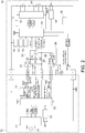
- FIG. 1 is a block diagram of an embodiment of the present invention, and is a block diagram of a state in which a battery pack 10 is connected to an electric tool 50.
- FIG. 2 is a block diagram of the embodiment of the present invention, and is a block diagram of a state in which the battery pack 10 is connected to a charger 70.
- each of the battery pack 10 and the electric tool 50 includes a positive terminal, an LS terminal, a V terminal, a T terminal, an LD terminal, and a negative terminal. Terminals having the same name in the battery pack 10 and the electric tool 50 are electrically connected to each other. As illustrated in FIG.
- the charger 70 includes a positive terminal, an LS terminal, a V terminal, a T terminal, and a negative terminal. Terminals having the same name in the battery pack 10 and the charger 70 are electrically connected to each other.
- the LS terminal of the battery pack 10 is an example of a first battery-side communication terminal, and the LS terminals of the electric tool 50 and the charger 70 are examples of a first body-side communication terminal.
- the T terminal of the battery pack 10 is an example of a second battery-side communication terminal, and the T terminals of the electric tool 50 and the charger 70 are examples of a second body-side communication terminal.
- the V terminal of the battery pack 10 is an example of a battery-side switching terminal, and the V terminals of the electric tool 50 and the charger 70 are examples of a body-side switching terminal.
- the battery pack 10 includes a plurality of (here, five) secondary battery cells 11 connected in series between the positive terminal and the negative terminal.
- a cell voltage monitoring IC 12 monitors a voltage of each secondary battery cell 11, determines that the battery pack 10 is overdischarged when a voltage of at least one secondary battery cell 11 falls below a predetermined value, determines that the battery pack 10 is overcharged when the voltage of the at least one secondary battery cell 11 exceeds a predetermined value for overcharge, and transmits an overdischarge detection signal or overcharge detection signal to a control unit (battery-side control unit) 15.
- a resistor R1 for current detection is connected in series with the secondary battery cell 11.
- a current detection circuit 14 detects an output current of the secondary battery cell 11 on the basis of a voltage across the resistor R1, and transmits a detection result to the control unit 15.
- a power supply circuit 13 generates an operation voltage VDD1 for the cell voltage monitoring IC 12 and the control unit 15 from the output voltage of the secondary battery cell 11.
- a battery voltage detection circuit 16 detects the output voltage of the secondary battery cell 11 and transmits a detection result to the control unit 15.
- a remaining capacity display means 17 is, for example, an LED, and displays (notifies) a remaining capacity of the battery pack 10 to a user under the control of the control unit 15.
- a cell temperature detection means 18 detects a temperature of the secondary battery cell 11 on the basis of a voltage of a thermistor TH disposed near the secondary battery cell 11 and outputs a voltage value corresponding to the temperature to the control unit 15.
- a remaining capacity display switch 19 is a switch for allowing the user to instruct the remaining capacity display means 17 to display the remaining capacity.
- the battery pack 10 includes a serial communication reception circuit 31 that forms a path for causing the control unit 15 to receive a serial communication signal (a digital signal) transmitted from the electric tool 50, and a temperature information transmission circuit 32 that forms a path for transmitting an analog voltage (temperature information of the secondary battery cell 11) at one terminal of the thermistor TH to the electric tool 50.
- the serial communication reception circuit 31 and the temperature information transmission circuit 32 are examples of a first communication circuit.
- the LS terminal of the battery pack 10 is selectively connected to either the serial communication reception circuit 31 or the temperature information transmission circuit 32 via a first switching circuit 21.
- the first switching circuit 21 includes a terminal connected to the LS terminal, a control terminal connected to the V terminal, and the other terminal selectively connected to either the serial communication reception circuit 31 or the temperature information transmission circuit 32 according to a signal input from the V terminal.
- the other terminal of the first switching circuit 21 is connected to the serial communication reception circuit 31, and when the signal from the V terminal is at a high level, the other terminal of the first switching circuit 21 is connected to the temperature information transmission circuit 32.
- the one terminal of the thermistor TH is connected to the other terminal of the first switching circuit 21.
- a switching element Q1 such as an FET is provided between the other terminal of the thermistor TH and a ground.
- a third switching circuit 23 includes one terminal connected to the V terminal, a control terminal connected to the control unit 15, and the other terminal selectively connected to either a control terminal (a gate) of the switching element Q1 or the one terminal (the other terminal of the first switching circuit 21) of the thermistor TH according to a signal input from the control unit 15.
- the battery pack 10 includes an identification information transmission circuit 35 that forms a path for transmitting an analog voltage (identification information of the battery pack 10) at one terminal of an identification resistor Ra to the electric tool 50, and a serial communication transmission circuit 36 that forms a path for transmitting a serial communication signal (a digital signal) directed from the control unit 15 to the electric tool 50.
- the identification information transmission circuit 35 and the serial communication transmission circuit 36 are examples of a second communication circuit.
- the T terminal of the battery pack 10 is selectively connected to either the identification information transmission circuit 35 or the serial communication transmission circuit 36 via a second switching circuit 22.
- the second switching circuit 22 includes one terminal connected to the T terminal, a control terminal connected to the control unit 15, and the other terminal selectively connected to either the identification information transmission circuit 35 or the serial communication transmission circuit 36 according to a signal input from the control unit 15.
- the one terminal of the identification resistor Ra is connected to the other terminal of the second switching circuit 22.
- An identification resistor Rb and a switching element Q2 such as an FET are connected in parallel between the other terminal of the identification resistor Ra and the ground.
- a control terminal (a gate) of the switching element Q2 is connected to the V terminal.
- a switching element Q3 such as an FET is provided between the LD terminal and the ground.
- a control terminal (a gate) of the switching element Q3 is connected to the control unit 15. When a signal input from the control unit 15 to the control terminal is at a high level, the switching element Q3 is turned ON, and when the signal is at a low level, the switching element Q3 is turned OFF.
- the electric tool 50 which is an example of an electrical apparatus, includes a motor 51 serving as a driving source, a trigger switch 52, a switching element Q5 such as an FET, and a resistor R5, which are connected in series between the positive terminal and the negative terminal.
- the motor 51 is a motor with a brush herein, but may be a brushless motor.
- a control terminal (a gate) of the switching element Q5 is connected to a control unit (body-side control unit) 55.
- a switch state detection circuit 53 detects on/off of the trigger switch 52 on the basis of a terminal voltage on the motor 51 side of the trigger switch 52 and transmits a detection result to the control unit 55.
- the control unit 55 When the trigger switch 52 is turned ON, the control unit 55 turns ON the switching element Q5 continuously or intermittently so that a driving current is supplied to the motor 51. Being intermittently ON is, for example, PWM control.
- a current detection circuit 54 detects a current flowing through the motor 51 on the basis of a voltage across the resistor R5, and transmits a detection result to the control unit 55.
- a power supply circuit 56 generates an operation voltage VDD2 of the control unit 55 from an input voltage from a positive terminal (the output voltage of the secondary battery cell 11).
- a battery voltage detection circuit 57 detects the output voltage of the secondary battery cell 11 on the basis of a voltage at the positive terminal, and transmits a detection result to the control unit 55.
- a remaining capacity display means 58 is, for example, an LED, and displays (notifies) a remaining capacity of the battery pack 10 to the user under the control of the control unit 55.
- the remaining capacity display switch 59 is a switch for allowing the user to instruct the remaining capacity display means 58 to display the remaining capacity.
- the control unit 55 includes terminals respectively connected to the LS terminal, the V terminal, the T terminal, and the LD terminal.
- One terminal of a resistor R6 is connected to a power supply line.
- a resistor R7 and a switching element Q6 such as an FET are connected in series between the other terminal of the resistor R6 and the ground.
- An interconnection point of the resistor R6 and the resistor R7 is connected to the LS terminal.
- a control terminal (a gate) of the switching element Q6 is connected to the control unit 55.
- a resistor R8 is provided between the power supply line and the T terminal.
- a resistor R9 is provided between the power supply line and the LD terminal.
- the charger 70 which is an example of an electrical apparatus, includes a charging circuit 71 between the positive terminal and the negative terminal.
- the charging circuit 71 generates charging power for the secondary battery cell 11 from power supplied from an AC power source 72 under the control of the control unit (a body-side control unit) 75.
- a resistor R11 is connected in series to the charging circuit 71.
- a current detection circuit 74 detects an output current of the charging circuit 71 (a charging current directed to the secondary battery cell 11) on the basis of a voltage across the resistor R11, and transmits a detection result to a control unit 75.
- a battery voltage detection circuit 77 detects the output voltage of the secondary battery cell 11 on the basis of a voltage at the positive terminal, and transmits the detection result to the control unit 75.
- the control unit 75 includes terminals respectively connected to the LS terminal, the V terminal, and the T terminal.
- One terminal of a resistor R12 is connected to the power supply line.
- a resistor R13 and a switching element Q8 such as an FET are connected in series between the other terminal of the resistor R12 and the ground.
- An interconnection point of the resistor R12 and the resistor R13 is connected to the LS terminal.
- a control terminal (a gate) of the switching element Q8 is connected to the control unit 75.
- a resistor R14 is provided between the power supply line and the T terminal.
- the control unit 55 of the electric tool 50 can switch between functions of the LS terminal on the basis of a signal transmitted to the battery pack 10 via the V terminal. Specifically, when the control unit 55 transmits a high-level signal from the V terminal, a connection destination of the other terminal of the first switching circuit 21 becomes the temperature information transmission circuit 32, and the control unit 55 can receive a voltage at the one terminal of the thermistor TH via the first switching circuit 21 and the LS terminal.
- the switching element Q1 Since the control unit 15 of the battery pack 10 normally sets a connection destination of the other terminal of the third switching circuit 23 to the control terminal of the switching element Q1, the switching element Q1 is turned ON when the signal at the V terminal is at a high level, such that an analog voltage according to the temperature of the secondary battery cell 11 is output to the one terminal (the temperature information transmission circuit 32) of the thermistor TH. Further, when the signal at the V terminal is at the high level, the switching element Q2 is turned ON, and the voltage at the T terminal becomes a first identification voltage obtained by dividing a power supply voltage VDD2 of the electric tool 50 using the resistor R8 and the resistor Ra.
- the control unit 55 transmits a low-level signal from the V terminal, the connection destination of the other terminal of the first switching circuit 21 becomes the serial communication reception circuit 31, and the serial communication signal can be transmitted to the control unit 15 of the battery pack 10 via the LS terminal.
- the serial communication signal is created by the switching element Q6 being ON and OFF.
- the switching element Q2 is turned OFF, and the voltage at the T terminal becomes a second identification voltage obtained by dividing the power supply voltage VDD2 of the electric tool 50 using the resistor R8 and a series combined resistor of the resistor Ra and the resistor Rb.
- the control unit 55 can obtain information of the battery pack 10 on the basis of both the first and second identification voltages.
- the control unit 75 of the charger 70 can switch between the functions of the LS terminal using a signal that is transmitted to the battery pack 10 via the V terminal, and can switch a voltage that is received from the T terminal to any one of the first and second identification voltages, similar to the control unit 55 of the electric tool 50.
- the control unit 15 of the battery pack 10 can switch functions of the T terminal by switching a connection destination of the other terminal of the second switching circuit 22. Specifically, when the connection destination of the other terminal of the second switching circuit 22 is the serial communication transmission circuit 36, the control unit 15 can transmit the serial communication signal to the electric tool 50 or the charger 70 via the second switching circuit 22 and the T terminal. On the other hand, when the connection destination of the second switching circuit 22 is the identification information transmission circuit 35, the control unit 15 can output an analog voltage at the one terminal of the identification resistor Ra to the electric tool 50 or the charger 70 via the second switching circuit 22 and the T terminal.
- Content of the serial communication signal that is transmitted from the electric tool 50 to the battery pack 10 include, for example, a type or model number of the electric tool 50, an overdischarge stop notification, an overdischarge display instruction, a threshold value for abnormality detection (for example, an overdischarge threshold value, an overcurrent threshold value, or a high temperature protection threshold value of the secondary battery cell 11), a display threshold value for a remaining amount display (a threshold value for switching between remaining capacity displays), an error log, use history information, and information from the battery pack 10 to be requested. All of pieces of information may be transmitted from the electric tool 50 to the battery pack 10 or only information requested from the battery pack 10 may be transmitted.
- Content of the serial communication signal that is transmitted from the charger 70 to the battery pack 10 includes, for example, a type or model number of the charger 70, an error log, use history information, and information from the battery pack 10 to be requested. All of pieces of information may be transmitted from the charger 70 to the battery pack 10, or only information requested from the battery pack 10 may be transmitted.
- Content of the serial communication signal that is transmitted from the battery pack 10 to the electric tool 50 includes, for example, a type or model number of the battery pack 10, a type of the secondary battery cell 11, an error log, use history information, and information from the electric tool 50 to be requested. All pieces of information may be transmitted from the battery pack 10 to the electric tool 50, or only information requested from the electric tool 50 may be transmitted.
- Content of the serial communication signal that is transmitted from the battery pack 10 to the charger 70 include, for example, a type or model number of the battery pack 10, a type of the secondary battery cell 11, charging conditions, an error log, use history information, and information from the charger 70 to be requested. All of pieces of information may be transmitted from the battery pack 10 to the charger 70, or only information requested from the charger 70 may be transmitted.
- the serial communication it is possible to notify of the identification information of the battery pack 10 more or in greater detail than voltages of the identification resistors Ra and Rb.
- a high signal or a low signal output from one control unit a microcomputer
- the other control unit a microcomputer
- the control unit 15 of the battery pack 10 sets the connection destination of the other terminal of the third switching circuit 23 to the one terminal of the thermistor TH (the other terminal of the first switching circuit 21). Since the control unit 75 of the charger 70 sets the signal at the V terminal to a high level during charging as will be described below, the connection destination of the other terminal of the first switching circuit 21 is the temperature information transmission circuit 32. Therefore, the signal (at a high level) at the V terminal is transmitted to the control unit 75 of the charger 70 via the third switching circuit 23, the first switching circuit 21, and the LS terminal, and the control unit 75 is notified that charging has been stopped.
- control unit 15 of the battery pack 10 detects any one of overcurrent, overdischarge, and an abnormally high temperature of the secondary battery cell 11, the control unit 15 turns ON the switching element Q3. Accordingly, the voltage at the LD terminal decreases from the power supply voltage VDD2 of the electric tool 50 to the ground potential, and the control unit 55 is notified that discharge is prohibited.
- FIG. 3 is a control flowchart of the electric tool 50.
- the control unit 55 turns ON the switching element Q5 continuously or intermittently so that the driving current is supplied to the motor 51 (S5).
- the operable state is a state in which all of a condition that a signal from the battery pack 10 indicates discharge permission (a signal from the LD terminal is at a high level), a condition that the battery pack 10 is not overdischarged, a condition that a current is not overcurrent, and a condition that the secondary battery cell 11 is not abnormally hot are satisfied.
- the control unit 55 turns OFF the switching element Q5, stops the supply of the driving current to the motor 51, and stops the motor 51 (S11).
- the motor 51 being no longer in the operable state includes that the control unit 15 detects falling of a motor current (that the motor current no longer flow) in a state in which the switch state detection circuit 53 is detecting ON of the trigger switch 52, in addition to the fact that at least one of the conditions that the motor 51 enters the operable state is no longer satisfied.
- the control unit 55 sets a signal to be output to the V terminal to a high level.
- the control unit 55 switches the signal to be output to the V terminal to a low level (S13). Accordingly, the battery pack 10 is switched from a mode in which the temperature information is output to the LS terminal to a mode in which the serial communication signal is received via the LS terminal.
- the control unit 55 executes communication control (S15). When the communication signal is not received for a predetermined time during execution of the communication control (YES in S17), the control unit 55 interrupts the serial communication (S20), switches the signal to be output to the V terminal to a high level (S23), and returns to step S1.
- the control unit 55 interrupts the serial communication (S19), switches the signal to be output to the V terminal to a high level (S21), returns to step S5 when the electric tool 50 is in the operable state (YES in S25), and returns to step S13 when the electric tool 50 is not in the operable state (NO in S25).
- the signal to be output to the V terminal is switched to the high level in steps S21 and S23, the battery pack 10 is switched from the mode in which the serial communication signal is received via the LS terminal to the mode in which the temperature information is output to the LS terminal.
- FIG. 4 is a flowchart illustrating a first example of the communication control (S15) of the electric tool 50 illustrated in FIG. 3 .
- an overdischarge stop command communication progression flag is not established (is not set) (NO in S151)
- the control unit 55 recognizes that a cause of stopping of the motor 51 is overdischarge (YES in S153).
- an overdischarge stop command communication end flag is not established (NO in S155)
- the control unit 55 transmits an overdischarge stop command to the battery pack 10 via the LS terminal (S157), establishes (sets) the overdischarge stop command communication progression flag (S159), and waits for a signal from the battery pack 10 (S17).
- the control unit 55 When the overdischarge stop command communication progression flag is set (YES in S151) and the control unit 55 receives an OK response to the overdischarge stop command from the battery pack 10 via the T terminal (YES in S161), the control unit 55 establishes the discharge stop command communication end flag (S163), and clears the overdischarge stop command communication progression flag (S165).
- the control unit 55 waits for a signal from the battery pack 10 (S17).
- control unit 55 When the control unit 55 does not receive the communication signal for a predetermined time (YES in S17), the control unit 55 clears the overdischarge stop command communication progression flag and interrupts the serial communication (S20). When the trigger switch 52 is turned ON (YES in S18), the control unit 55 clears the overdischarge stop command communication progression flag and interrupts the serial communication (S19).
- the control unit 55 may have a function of transmitting the overcurrent stop command to the battery pack 10 when the cause of stopping of the motor 51 is an overcurrent. In this case, the "overdischarge" in FIG. 4 and the above description regarding FIG. 4 can be replaced with an "overcurrent" for application.
- the control unit 15 of the battery pack 10 can discriminate that the electric tool 50 is no longer in the operable state. Specifically, in a case in which an abnormality signal (a signal from the LD terminal) is not input from the battery pack 10, the control unit 55 of the electric tool 50 or the control unit 15 of the battery pack 10 can determine that the electric tool 50 becomes abnormal (is no longer in the operable state) when a current is no longer detected in the resistor R5 or the resistor R1 by the current detection circuit 54 or the current detection circuit 14 even though the switch state detection circuit 53 detects ON of the trigger switch 52.
- an abnormality signal a signal from the LD terminal
- a trigger switch state detection means (not illustrated) of the electric tool 50 is provided on the battery pack 10 side, and when the control unit 15 detects, through the current detection circuit 14, falling of a motor current flowing through the motor 51 (that the motor current no longer flows) in a state in which an ON state of the trigger switch 52 is continued, the battery pack 10 can discriminate that the electric tool 50 is no longer in the operable state. In this case, the remaining capacity display means 17 and 58 can be used to inform that the electric tool 50 is no longer in the operable state for some reasons.
- the control unit 55 may have a function of transmitting a high temperature abnormality stop command to the battery pack 10 when a cause of stopping of the motor 51 is a high temperature abnormality of the secondary battery cell 11. In this case, the "overdischarge" in FIG. 4 and the above description regarding FIG. 4 is replaced with as an "high temperature abnormality" for application.
- FIG. 5 is a control flowchart of the battery pack 10.
- the control unit 15 sets a signal applied to the control terminal of the switching element Q3 to a low level (releases a discharge stop signal) (S45).
- the control unit 15 sets the signal applied to the control terminal of the switching element Q3 to a high level (outputs the discharge stop signal) (S47).
- the control unit 15 may determine that the current is an overcurrent in a case in which the control unit 15 receives the overcurrent stop command from the control unit 55 of the electric tool 50, in addition to the case in which the motor current exceeds a set overcurrent threshold value thereof, in the determination as to whether or not there is an overcurrent (S41).
- the control unit 15 may determine that the secondary battery cell 11 is at an abnormally high temperature in a case in which the control unit 15 receives the high temperature abnormal stop command from the control unit 55 of the electric tool 50, in addition to a case in which the temperature of the secondary battery cell 11 has exceeded the set high temperature protection threshold value thereof, in the determination (S43) as to whether the secondary battery cell 11 is at an abnormally high temperature.
- the control unit 15 sets the connection destination of the other terminal of the third switching circuit 23 to the control terminal of the switching element Q1 such that a charge stop signal is not output from the LS terminal (S51).
- the chargeable state is a state in which all of a condition that the battery pack 10 is not overcharged, a condition that a current is not an overcurrent, and a condition that the secondary battery cell 11 is not at an abnormally high temperature are satisfied.
- control unit 15 sets the connection destination of the other terminal of the third switching circuit 23 to the one terminal of the thermistor TH (the other terminal of the first switching circuit 21) such that the charge stop signal is output from the LS terminal (S53).
- the control unit 15 When a communication flag is not established (NO in S55) and the control unit 15 receives the serial communication signal from the electric tool 50 or the charger 70 via the LS terminal (S71), the control unit 15 establishes the communication flag (S73), sets the connection destination of the other terminal of the second switching circuit 22 to the serial communication transmission circuit 36, switches a mode from a mode in which the identification information of the battery pack 10 is output to the T terminal to a mode in which the serial communication signal is transmitted via the T terminal (S75), and executes communication control (S59). When the communication flag is established (YES in S55) and a state in which no communication signal is received for a predetermined time does not continue (NO in S57), the control unit 15 executes communication control (S59).
- the control unit 15 clears the communication flag (S77), sets the connection destination of the other terminal of the second switching circuit 22 to the identification information transmission circuit 35, and switches the mode from the mode in which the serial communication signal is transmitted via the T terminal to the mode in which the identification information of the battery pack 10 is output to the T terminal (S79).
- the control unit 15 executes remaining capacity display control (S60).
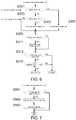
- FIG. 6 is a flowchart illustrating a first example of the overdischarge determination (S30) of the battery pack 10 illustrated in FIG. 5 .
- the control unit 15 clears an overdischarge (voltage) flag (S305).
- the control unit 15 establishes the overdischarge (voltage) flag (S307).
- the control unit 15 clears an overdischarge (communication) flag (S311).
- the overdischarge (voltage) flag is established (YES in S313) or when the overdischarge (communication) flag is established (YES in S315), the control unit 15 determines that the battery pack 10 is overdischarged.
- the overdischarge (voltage) flag is not established (NO in S313) and the overdischarge (communication) flag is not established (NO in S315), the control unit 15 determines that the battery pack 10 is not overdischarged.
- FIG. 7 is a flowchart illustrating a first example of the communication control (S59) of the battery pack 10 illustrated in FIG. 5 .
- the control unit 15 receives the overdischarge stop command from the electric tool 50 via the LS terminal (YES in S591), the control unit 15 establishes the overdischarge (communication) flag (S592) and transmits an OK response via the T terminal (S593).
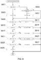
- FIG. 8 is a flowchart of the remaining capacity display control (S60) of the battery pack 10 illustrated in FIG. 5 .
- the remaining capacity display means 17 includes four LEDs.
- the control unit 15 establishes a display ON flag (S603).
- the remaining capacity display switch 19 is not turned ON (NO in S601) and when three seconds or more have elapsed after the remaining capacity display switch 19 is turned OFF (YES in S605), the control unit 15 clears the display ON flag (S607).
- the display ON flag is not established (NO in S609), the control unit 15 turns OFF the LEDs of the remaining capacity display means 17 (S611).
- the control unit 15 causes one of the LEDs of the remaining capacity display means 17 to blink (S615).
- the control unit 15 turns ON the four LEDs of the remaining capacity display means 17 (S619).
- the control unit 15 When the voltage of the secondary battery cell 11 is equal to or lower than a first display threshold value V4 (NO in S617) and higher than a second display threshold value V3 (YES in S621), the control unit 15 turns on the three LEDS of the LEDs of the remaining capacity display means 17 (S623). When the voltage of the secondary battery cell 11 is equal to or lower than the second display threshold value V3 (NO in S621) and higher than the third display threshold value V2 (YES in S625), the control unit 15 turns on the two LEDS of the LEDs of the remaining capacity display means 17 (S627).
- the control unit 15 When the voltage of the secondary battery cell 11 is equal to or lower than the third display threshold value V2 (NO in S625), the control unit 15 turns on one of the LEDs of the remaining capacity display means 17 (S629).
- the control unit 15 may cause the LEDs of the remaining capacity display means 17 to blink in an aspect different from those at the time overdischarge (S615) regardless of the operation of the remaining capacity display switch 19 or may cause the number of LEDs different from those at the time overdischarge (S615) to blink.
- control unit 15 may cause the LEDs of the remaining capacity display means 17 to blink in aspects different from those at the time overdischarge (S615) and at the time of overcurrent regardless of the operation of the remaining capacity display switch 19 or may cause the number of LEDs different from those at the time overdischarge (S615) and at the time of overcurrent to blink.
- FIG. 9 is a flowchart illustrating a second example of the communication control (S15) of the electric tool 50 illustrated in FIG 3 .
- the control unit 55 transmits an overdischarge threshold value to the battery pack 10 via the LS terminal (S157a), establishes (sets) the overdischarge threshold value communication progression flag (S159a), and waits for a signal from the battery pack 10 (S17).
- the control unit 55 When the overdischarge threshold value communication progression flag is established (YES in S151a) and the control unit 55 receives an OK response to the overdischarge threshold value from the battery pack 10 via the T terminal (YES in S161a), the control unit 55 establishes the overdischarge threshold value communication end flag (S163a), clears the overdischarge threshold value communication progression flag (S165a), and waits for a signal from the battery pack 10 (S17). When the overdischarge threshold value communication end flag is set (YES in S155a) or when an OK response to the overdischarge threshold value is not received from the battery pack 10 (NO in S161a), the control unit 55 waits for a signal from the battery pack 10 (S17).
- control unit 55 When the control unit 55 does not receive the communication signal for a predetermined time (YES in S17), the control unit 55 clears the overdischarge threshold value communication progression flag and interrupts the serial communication (S20). When the trigger switch 52 is turned ON (YES in S18), the control unit 55 clears the overdischarge threshold value communication progression flag and interrupts the serial communication (S19). The control unit 55 may transmit an overcurrent threshold value to the battery pack 10. In this case, the "overdischarge" in FIG. 9 and the above description regarding FIG. 9 is replaced with as an "overcurrent" for application.
- the control unit 15 of the battery pack 10 may determine that there is an overcurrent in a case in which the motor current has exceeded the overcurrent threshold value received from the control unit 55 of the electric tool 50, in addition to the case in which the motor current exceeds a set overcurrent threshold value thereof.
- the control unit 55 may transmit the high temperature protection threshold value to the battery pack 10. In this case, the "overdischarge" in FIG. 9 and the above description regarding FIG. 9 is replaced with as "high temperature protection" for application.
- the determination as to whether or not the secondary battery cell 11 is at an abnormally high temperature S43 in FIG.
- the control unit 15 of the battery pack 10 may determine that the secondary battery cell 11 is at an abnormally high temperature in a case in which the temperature of the secondary battery cell 11 has exceeded the high temperature protection threshold value received from the control unit 55 of the electric tool 50, in addition to a case in which the temperature of the secondary battery cell 11 has exceeded the set high temperature protection threshold value thereof.
- the control unit 15 of the battery pack 10 may determine that the secondary battery cell 11 is at an abnormally high temperature in a case in which the temperature of the secondary battery cell 11 has exceeded the high temperature protection threshold value received from the control unit 55 of the electric tool 50, in addition to a case in which the temperature of the secondary battery cell 11 has exceeded the set high temperature protection threshold value thereof.
- a high-output tool it is possible to suitably cope with a time lag of a voltage of the thermistor TH by setting a high temperature protection threshold value in the electric tool 50 to be lower than that of the battery pack 10.
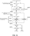
- FIG. 10 is a flowchart illustrating a second example of the overdischarge determination (S30) of the battery pack 10 illustrated in FIG. 5 .
- This flowchart is different from that in the first example illustrated in FIG. 6 in that a process of establishing the overdischarge (communication) flag (S310) when the voltage of the secondary battery cell 11 is lower than an overdischarge detection voltage VLO' (YES in S308) is added, and a process of putting 0 into the overdischarge detection voltage VLO' (S312) when the charging current has been detected (YES in S309) is added, and is the same as that in the first example illustrated in FIG. 6 in other points.
- the overdischarge detection voltages VLO and VLO' are both threshold values for determining whether or not the battery pack 10 is overdischarged.
- VLO is a threshold value that is held by the battery pack 10 itself in advance
- VLO' is a threshold value transmitted from the electric tool 50.
- FIG. 11 is a flowchart illustrating a second example of the communication control (S59) of the battery pack 10 illustrated in FIG. 5 .
- the control unit 15 receives the overdischarge threshold value from the electric tool 50 via the LS terminal (YES in S591a)
- the control unit 15 puts the received overdischarge threshold value into VLO' (S592a) and transmits an OK response via the T terminal. (S593a).
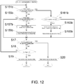
- FIG. 12 is a flowchart illustrating a third example of the communication control (S15) of the electric tool 50 illustrated in FIG. 3 .
- This flowchart is different from that of the second example illustrated in FIG. 9 in that a display threshold value for switching a remaining amount display in addition to the overdischarge threshold value is also transmitted from the electric tool 50 to the battery pack 10, and is the same as from that of the second example illustrated in FIG. 9 in other respects.
- the control unit 55 transmits the display and overdischarge threshold values to the battery pack 10 via the LS terminal (S157b), establishes (sets) the display and overdischarge threshold value communication progression flag (S159b), and waits for a signal from the battery pack 10 (S17).
- the control unit 55 establishes the display and overdischarge threshold value communication end flag (S163b), clears the display and overdischarge threshold value communication progression flag (S165b), and waits for a signal from the battery pack 10 (S17).
- the control unit 55 waits for a signal from the battery pack 10 (S17).
- the control unit 55 clears the display and overdischarge threshold value communication progression flag and interrupts the serial communication (S20).
- the trigger switch 52 is turned ON (YES in S18)
- the control unit 55 clears the display and overdischarge threshold value communication progression flag and interrupts serial communication (S19).
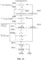
- FIG. 13 is a flowchart illustrating a third example of the overdischarge determination (S30) of the battery pack 10 illustrated in FIG. 5 .
- This flowchart is different from the second example illustrated in FIG. 10 in that a process of detecting a charging current (YES in S309), putting 0 into the overdischarge detection voltage VLO' (S312), and putting respective initial values V4bat, V3bat, and V2bat into the first display threshold value V4, the second display threshold value V3, and the third display threshold value V2 (S312a) is added, and is the same as in the second example in other respects.
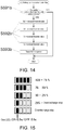
- FIG. 14 is a flowchart illustrating a third example of the communication control (S59) of the battery pack 10 illustrated in FIG. 5 .
- the control unit 15 receives the display and overdischarge threshold values from the electric tool 50 via the LS terminal (YES in S591b)
- the control unit 15 puts the received overdischarge threshold value into VLO' (S592b), puts the received display threshold value into V4, V3, and V2 (S592b), and transmits an OK response via the T terminal (S593b).
- FIG. 15 is an illustrative diagram illustrating a display example of the remaining capacity display means 17 of the battery pack 10.
- Five display examples illustrated in FIG. 15 are arranged from the top in descending order of remaining capacity.
- ON of four LEDs at the top corresponds to a case in which the voltage of the secondary battery cell 11 is higher than V4, and the remaining capacity is 100 to 75%.
- ON of three LEDs that is second one from the top corresponds to a case in which the voltage of the secondary battery cell 11 is equal to or lower than the first display threshold value V4 and higher than the second display threshold value V3, and the remaining capacity is 75 to 50%.
- ON of two LEDs that is third one from the top corresponds to a case in which the voltage of the secondary battery cell 11 is equal to or lower than the second display threshold value V3 and higher than the third display threshold value V2, and the remaining capacity is 50 to 25%.
- ON of one LED that is fourth one from the top corresponds to a case in which the voltage of the secondary battery cell 11 is equal to or lower than the third display threshold value V2 but the battery pack 10 is not overdischarged, and the remaining capacity is 25% or less.
- Blinking of one LED that is fifth one from the top both ON and OFF are, for example, at intervals of 0.5 seconds) corresponds to a case of overdischarge, and this is in a state in which discharge has been prohibited.
- FIG. 16 is a time chart illustrating an example of an operation in the block diagram illustrated in FIG 1 .
- the trigger switch 52 is turned ON at time t1
- a current begins to flow through the motor 51.
- the LS terminal of the battery pack 10 is in a temperature detection mode, an analog voltage indicating the temperature information of the secondary battery cell 11 is output from the LS terminal, and the analog voltage start to increase at the same time as the current starts to flow through the motor 51.
- the T terminal of the battery pack 10 is in a battery discrimination mode, and an analog voltage indicating the identification information of the battery pack 10 is output from the T terminal.
- the control unit 55 of the electric tool 50 detects overdischarge at time t2
- the control unit 55 turns OFF the switching element Q5 connected in series with the motor 51 to interrupt the current flowing through the motor 51.
- the control unit 55 switches the signal at the V terminal to a low level. Accordingly, the LS terminal is switched to a communication mode.
- the control unit 55 transmits a serial communication signal to the control unit 15 of the battery pack 10 via the LS terminal.
- This serial communication signal includes the overdischarge stop command indicating that the electric tool 50 has detected overdischarge and stopped the motor 51.
- the control unit 15 switches the T terminal to the communication mode and transmits the serial communication signal to the control unit 55 of the electric tool 50 via the T terminal.
- the control unit 15 of the battery pack 10 switches the signal at the LD terminal from the high level to the low level by setting a voltage at the control terminal of the switching element Q3 connected to the LD terminal to a high level. This is because it has been notified that there is overdischarge using the serial communication signal from the control unit 55 of the electric tool 50.
- the control unit 55 of the electric tool 50 switches the signal at the V terminal to the high level, the LS terminal of the battery pack 10 enters the temperature detection mode, and the T terminal enters the battery discrimination mode.
- Serial communication is performed in a state in which the motor 51 does not rotate.
- serial communication is performed after the overdischarge has been detected in FIG. 16 , a configuration in which, after the trigger switch 52 is turned OFF or when a switch for starting serial communication is operated in a case in which the switch for starting serial communication is provided, the voltage at the V terminal is switched to a low level may be adopted.
- FIG. 17 is a control flowchart of the charger 70.
- the control unit 75 When the battery pack 10 is connected (YES in S81), the control unit 75 outputs a low-level signal to the V terminal, switches the LS terminal to the communication mode (S83), and executes communication control (S85).
- the control unit 75 can recognize the connection of the battery pack 10 to the charger 70 from a voltage at the LS terminal or a voltage at the T terminal.
- the control unit 75 does not receive a communication signal for a predetermined time (YES in S87)
- the control unit 75 outputs a high-level signal to the V terminal and switches the LS terminal to the temperature detection mode (S89).
- the control unit 75 sets a charging voltage on the basis of the voltage at the T terminal (the analog voltage indicating the identification information of the battery pack 10) or the identification information of the battery pack 10 obtained through serial communication (S91), sets a charging current (S92), and turns ON a charging output (starts supply of the charging current) (S93).
- the chargeable state is a state in which all of a condition that the battery pack 10 is mounted (a discrimination from the voltages at the LS terminal and the T terminal), a condition that no charge stop signal is transmitted from the battery pack 10 (a discrimination from the voltage at the LS terminal), a condition that the secondary battery cell 11 is not at an abnormally high temperature (a discrimination from the voltage at the LS terminal), a condition that the secondary battery cell 11 is a type of battery that can be charged by the charger 70 (a discrimination from the voltage at the T terminal), and a condition that the battery pack 10 is not fully charged (a discrimination from the voltage at the positive terminal) are satisfied.
- the control unit 75 turns OFF the charging output (stops the supply of the charging current) (S95). In the determination as to the chargeable state in step S94, it is not necessary to check whether or not the secondary battery cell 11 is a type of battery that can be charged by the charger 70, unlike the discrimination in step S90.
- the control unit 75 returns to step S81.
- FIG. 18 is a block diagram of another embodiment of the present invention, and is a block diagram illustrating a state in which the battery pack 10 has been connected to the electric tool 50.
- the battery pack 10 includes a switching element Q9 such as an FET between the T terminal and the ground.
- a control terminal (a gate) of the switching element Q9 is connected to the control unit 15.
- an LD terminal is selectively connected to either a serial communication reception circuit 62 or a discharge permission/prohibition signal reception circuit 61 via a fourth switching circuit 60.
- the fourth switching circuit 60 includes one terminal connected to the LD terminal, a control terminal connected to the T terminal, and the other terminal selectively connected to any one of the serial communication reception circuit 62 and the discharge permission/prohibition signal reception circuit 61 according to a signal input from the T terminal.
- the other terminal of the fourth switching circuit 60 is connected to the serial communication reception circuit 62, and when the signal from the T terminal is at a high level, the other terminal of the fourth switching circuit 60 is connected to the discharge permission/prohibition signal reception circuit 61.
- the control unit 15 sets the signal input to the control terminal of the switching element Q9 to a high level, the voltage at the T terminal reaches a low level (a ground level), and the circuit of the LD terminal of the electric tool 50 is switched to the communication mode (a connection destination of the other terminal of the fourth switching circuit 60 is the serial communication reception circuit 62).
- a voltage of the discharge permission/prohibition signal reception circuit 61 becomes indefinite, but the control unit 55 regards this as discharge permission and performs control.
- the control unit 55 receives the serial communication signal.
- the control unit 55 sets the signal to be output to the V terminal to a low level, switches the LS terminal to the communication mode, and responds to the serial communication signal.
- Discharge permission/prohibition is desired to be transferred to the battery pack 10, and the communication can be started at any timing in a discharge permission state. Even when the discharge is desired to be prohibited, there is no problem if the communication is interrupted and a discharge prohibition signal is output after the communication is started to detect ON of the trigger switch 52 or the motor current.
- the control unit 15 can determine (set) that no communication is performed when the temperature of the secondary battery cell 11 is high, when a current is flowing, or when the voltage of the secondary battery cell 11 is low or high.
Landscapes
- Engineering & Computer Science (AREA)
- General Chemical & Material Sciences (AREA)
- Chemical & Material Sciences (AREA)
- Chemical Kinetics & Catalysis (AREA)
- Electrochemistry (AREA)
- Manufacturing & Machinery (AREA)
- Power Engineering (AREA)
- Microelectronics & Electronic Packaging (AREA)
- Secondary Cells (AREA)
- Charge And Discharge Circuits For Batteries Or The Like (AREA)
- Battery Mounting, Suspending (AREA)
- Portable Power Tools In General (AREA)
- Protection Of Static Devices (AREA)
Applications Claiming Priority (3)
| Application Number | Priority Date | Filing Date | Title |
|---|---|---|---|
| JP2017156314 | 2017-08-14 | ||
| JP2017156315 | 2017-08-14 | ||
| PCT/JP2018/028262 WO2019035338A1 (ja) | 2017-08-14 | 2018-07-27 | 電池パック及び電気機器 |
Publications (2)
| Publication Number | Publication Date |
|---|---|
| EP3671891A1 true EP3671891A1 (de) | 2020-06-24 |
| EP3671891A4 EP3671891A4 (de) | 2021-04-14 |
Family
ID=65362281
Family Applications (1)
| Application Number | Title | Priority Date | Filing Date |
|---|---|---|---|
| EP18846806.0A Pending EP3671891A4 (de) | 2017-08-14 | 2018-07-27 | Batteriepack und elektrische vorrichtung |
Country Status (5)
| Country | Link |
|---|---|
| US (1) | US11637433B2 (de) |
| EP (1) | EP3671891A4 (de) |
| JP (2) | JP7103360B2 (de) |
| CN (1) | CN111033792B (de) |
| WO (1) | WO2019035338A1 (de) |
Cited By (1)
| Publication number | Priority date | Publication date | Assignee | Title |
|---|---|---|---|---|
| EP4358357A1 (de) * | 2022-10-12 | 2024-04-24 | Techtronic Cordless GP | Batteriepack |
Families Citing this family (9)
| Publication number | Priority date | Publication date | Assignee | Title |
|---|---|---|---|---|
| WO2019105465A1 (zh) | 2017-11-30 | 2019-06-06 | 南京德朔实业有限公司 | 电动工具系统及用于该系统的升级方法 |
| US11029941B2 (en) | 2017-11-30 | 2021-06-08 | Nanjing Chervon Industry Co., Ltd. | Electrical device and program update method thereof |
| CN109946532B (zh) * | 2017-12-21 | 2024-03-19 | 南京泉峰科技有限公司 | 适用于工具系统部件的诊断装置和诊断方法 |
| JP7136207B2 (ja) * | 2018-07-31 | 2022-09-13 | 工機ホールディングス株式会社 | 直流電源装置 |
| JP7336264B2 (ja) * | 2019-05-29 | 2023-08-31 | 株式会社マキタ | バッテリパック |
| JP7452388B2 (ja) * | 2020-02-17 | 2024-03-19 | トヨタ自動車株式会社 | バッテリー制御装置、方法、プログラム、及び車両 |
| WO2022138506A1 (ja) * | 2020-12-23 | 2022-06-30 | 工機ホールディングス株式会社 | 電池パック及び電気機器システム |
| CN118826184A (zh) * | 2023-04-17 | 2024-10-22 | 创科无线普通合伙 | 电池包 |
| CN121420441A (zh) * | 2023-06-29 | 2026-01-27 | 工机控股株式会社 | 电气设备主体及电气设备 |
Family Cites Families (28)
| Publication number | Priority date | Publication date | Assignee | Title |
|---|---|---|---|---|
| JPH04147076A (ja) * | 1990-10-09 | 1992-05-20 | Fujitsu Ltd | 電源装置及びそのバックアップ電源のチェック方式 |
| US5939856A (en) | 1997-05-30 | 1999-08-17 | Motorola, Inc. | Battery and charging system using switchable coding devices |
| JPH11150809A (ja) * | 1997-09-15 | 1999-06-02 | Honda Motor Co Ltd | バッテリ・レンタルシステム |
| JP3715089B2 (ja) * | 1997-09-15 | 2005-11-09 | 本田技研工業株式会社 | バッテリ充電装置 |
| JP4206917B2 (ja) * | 2003-12-01 | 2009-01-14 | 株式会社ニコン | 電池、カメラ、カメラシステムおよび携帯機器 |
| JP2005235676A (ja) * | 2004-02-23 | 2005-09-02 | Matsushita Electric Ind Co Ltd | 電池パック |
| JP2007104745A (ja) * | 2005-09-30 | 2007-04-19 | Nec Corp | 移動体通信端末装置および電池パック |
| JP4943882B2 (ja) * | 2007-02-08 | 2012-05-30 | パナソニック株式会社 | 認証装置、被認証装置、及び電池認証システム |
| JP4933298B2 (ja) | 2007-02-19 | 2012-05-16 | 株式会社マキタ | 通信システム、電池パック、及び電池パック接続機器 |
| JP5097468B2 (ja) * | 2007-07-31 | 2012-12-12 | パナソニック株式会社 | 電池パック、電気機器、及び遠隔制御システム |
| JP5085284B2 (ja) * | 2007-11-09 | 2012-11-28 | ソニーモバイルコミュニケーションズ株式会社 | 携帯電話端末および通信システム |
| JP5815195B2 (ja) | 2008-09-11 | 2015-11-17 | ミツミ電機株式会社 | 電池状態検知装置及びそれを内蔵する電池パック |
| JP5206989B2 (ja) * | 2009-09-01 | 2013-06-12 | 三菱自動車工業株式会社 | 車両用二次電池装置 |
| JP2011211861A (ja) | 2010-03-30 | 2011-10-20 | Hitachi Koki Co Ltd | 電池パック及び電動工具 |
| JP5497594B2 (ja) | 2010-09-10 | 2014-05-21 | 関西電力株式会社 | 蓄電装置を用いたアンシラリーサービス提供装置 |
| JP5498414B2 (ja) | 2011-02-28 | 2014-05-21 | 株式会社東芝 | 試験装置および電池パックの試験方法 |
| JP2013050358A (ja) * | 2011-08-30 | 2013-03-14 | Sanyo Electric Co Ltd | 二次電池の残容量の算出方法、電池駆動装置、パック電池及び情報処理システム |
| JP5542781B2 (ja) | 2011-11-10 | 2014-07-09 | 株式会社日立製作所 | 蓄電池制御システム及び蓄電池制御方法 |
| JP2014073020A (ja) * | 2012-09-28 | 2014-04-21 | Hitachi Koki Co Ltd | 電池パック及び充電装置 |
| WO2014050152A1 (en) * | 2012-09-28 | 2014-04-03 | Hitachi Koki Co., Ltd. | Battery charger and battery pack |
| JP2014072945A (ja) | 2012-09-28 | 2014-04-21 | Hitachi Koki Co Ltd | 充電システム、電池パック、及び充電装置 |
| JP6053442B2 (ja) * | 2012-10-10 | 2016-12-27 | キヤノン株式会社 | 通信システム、受信装置、送信装置、制御方法、及びプログラム |
| JP2014103717A (ja) * | 2012-11-16 | 2014-06-05 | Toshiba Corp | 充放電指示装置、充放電システム、充放電管理方法ならびにプログラム |
| JP2014144699A (ja) * | 2013-01-29 | 2014-08-14 | Sanyo Electric Co Ltd | 電動自転車及び充電器、回路 |
| CN105009401B (zh) * | 2013-03-22 | 2019-06-28 | 工机控股株式会社 | 电池组和电气设备 |
| JP6233212B2 (ja) * | 2014-07-03 | 2017-11-22 | 株式会社デンソー | 組電池システム |
| JP6706844B2 (ja) * | 2014-07-11 | 2020-06-10 | パナソニックIpマネジメント株式会社 | 蓄電池パック |
| CN107636479B (zh) * | 2015-09-11 | 2021-06-08 | 工机控股株式会社 | 电池诊断装置及电池组 |
-
2018
- 2018-07-27 WO PCT/JP2018/028262 patent/WO2019035338A1/ja not_active Ceased
- 2018-07-27 JP JP2019536719A patent/JP7103360B2/ja active Active
- 2018-07-27 US US16/638,757 patent/US11637433B2/en active Active
- 2018-07-27 CN CN201880052649.4A patent/CN111033792B/zh active Active
- 2018-07-27 EP EP18846806.0A patent/EP3671891A4/de active Pending
-
2022
- 2022-07-06 JP JP2022108864A patent/JP7494881B2/ja active Active
Cited By (1)
| Publication number | Priority date | Publication date | Assignee | Title |
|---|---|---|---|---|
| EP4358357A1 (de) * | 2022-10-12 | 2024-04-24 | Techtronic Cordless GP | Batteriepack |
Also Published As
| Publication number | Publication date |
|---|---|
| US11637433B2 (en) | 2023-04-25 |
| CN111033792A (zh) | 2020-04-17 |
| EP3671891A4 (de) | 2021-04-14 |
| JP2022140450A (ja) | 2022-09-26 |
| US20200227931A1 (en) | 2020-07-16 |
| CN111033792B (zh) | 2023-07-11 |
| JP7103360B2 (ja) | 2022-07-20 |
| JP7494881B2 (ja) | 2024-06-04 |
| JPWO2019035338A1 (ja) | 2020-08-20 |
| WO2019035338A1 (ja) | 2019-02-21 |
Similar Documents
| Publication | Publication Date | Title |
|---|---|---|
| EP3671891A1 (de) | Batteriepack und elektrische vorrichtung | |
| US10270263B2 (en) | System and method for charging a battery pack | |
| CN109698532B (zh) | 充电控制装置、蓄电池组以及充电器 | |
| EP2929612B1 (de) | Ladevorrichtung | |
| CN114448010A (zh) | 一种充放电的控制系统、方法及电池包 | |
| CN112366789A (zh) | 智能连接装置、启动电源以及电瓶夹 | |
| JP7336264B2 (ja) | バッテリパック | |
| JP2023549947A (ja) | スマート接続装置、始動電源及びバッテリークランプ | |
| JP2001283934A (ja) | 電池パック識別装置及び電池パック | |
| EP3352324A1 (de) | Ladeadapter für zwei akkus | |
| WO2014050152A1 (en) | Battery charger and battery pack | |
| CN120300966A (zh) | 一种电池包 | |
| CN112087007A (zh) | 一种电池包 | |
| CN112087010B (zh) | 一种电池包 | |
| JP7272371B2 (ja) | 電気機器システム | |
| JP2022047802A (ja) | 電子機器、電池パック、制御方法およびプログラム | |
| JPWO2017014007A1 (ja) | 電池パック | |
| WO2015166907A1 (ja) | 電池パック及び充電装置 | |
| CN119582387A (zh) | 一种充电系统 | |
| JP2021045006A (ja) | バッテリパック及び充電システム | |
| CN112087009A (zh) | 一种电池包 | |
| JPH0637699A (ja) | コードレス電話装置 | |
| CN118696476A (zh) | 充电适配器、充电器以及电池组的充电方法 | |
| JP2013143789A (ja) | 電力供給装置、電力供給方法及びプログラム | |
| CN112087008A (zh) | 一种电池包工作状态的识别方法及电池包 |
Legal Events
| Date | Code | Title | Description |
|---|---|---|---|
| STAA | Information on the status of an ep patent application or granted ep patent |
Free format text: STATUS: THE INTERNATIONAL PUBLICATION HAS BEEN MADE |
|
| PUAI | Public reference made under article 153(3) epc to a published international application that has entered the european phase |
Free format text: ORIGINAL CODE: 0009012 |
|
| STAA | Information on the status of an ep patent application or granted ep patent |
Free format text: STATUS: REQUEST FOR EXAMINATION WAS MADE |
|
| 17P | Request for examination filed |
Effective date: 20200213 |
|
| AK | Designated contracting states |
Kind code of ref document: A1 Designated state(s): AL AT BE BG CH CY CZ DE DK EE ES FI FR GB GR HR HU IE IS IT LI LT LU LV MC MK MT NL NO PL PT RO RS SE SI SK SM TR |
|
| AX | Request for extension of the european patent |
Extension state: BA ME |
|
| DAV | Request for validation of the european patent (deleted) | ||
| DAX | Request for extension of the european patent (deleted) | ||
| REG | Reference to a national code |
Ref country code: DE Ref legal event code: R079 Free format text: PREVIOUS MAIN CLASS: H01M0002100000 Ipc: H01M0010480000 |
|
| A4 | Supplementary search report drawn up and despatched |
Effective date: 20210315 |
|
| RIC1 | Information provided on ipc code assigned before grant |
Ipc: H01M 10/48 20060101AFI20210309BHEP Ipc: H02J 7/00 20060101ALI20210309BHEP Ipc: B25F 5/02 20060101ALI20210309BHEP Ipc: H01M 50/20 20210101ALI20210309BHEP |
|
| STAA | Information on the status of an ep patent application or granted ep patent |
Free format text: STATUS: EXAMINATION IS IN PROGRESS |
|
| 17Q | First examination report despatched |
Effective date: 20220627 |