EP3671930A1 - Électrolyte hybride à semi-conducteur - Google Patents
Électrolyte hybride à semi-conducteur Download PDFInfo
- Publication number
- EP3671930A1 EP3671930A1 EP18214047.5A EP18214047A EP3671930A1 EP 3671930 A1 EP3671930 A1 EP 3671930A1 EP 18214047 A EP18214047 A EP 18214047A EP 3671930 A1 EP3671930 A1 EP 3671930A1
- Authority
- EP
- European Patent Office
- Prior art keywords
- ion conductive
- solid state
- ceramic
- conductive matrix
- state electrolyte
- Prior art date
- Legal status (The legal status is an assumption and is not a legal conclusion. Google has not performed a legal analysis and makes no representation as to the accuracy of the status listed.)
- Withdrawn
Links
- 239000007787 solid Substances 0.000 title claims abstract description 100
- 239000003792 electrolyte Substances 0.000 title claims abstract description 99
- 239000011159 matrix material Substances 0.000 claims abstract description 113
- 229910010293 ceramic material Inorganic materials 0.000 claims abstract description 69
- 229910052751 metal Inorganic materials 0.000 claims abstract description 30
- 239000002184 metal Substances 0.000 claims abstract description 30
- 229920000642 polymer Polymers 0.000 claims abstract description 30
- 150000003839 salts Chemical class 0.000 claims abstract description 16
- 150000002500 ions Chemical class 0.000 claims description 127
- 239000000463 material Substances 0.000 claims description 44
- 239000000919 ceramic Substances 0.000 claims description 36
- 238000000034 method Methods 0.000 claims description 34
- 239000012700 ceramic precursor Substances 0.000 claims description 19
- 239000000376 reactant Substances 0.000 claims description 19
- 239000007773 negative electrode material Substances 0.000 claims description 16
- 238000004519 manufacturing process Methods 0.000 claims description 15
- 230000015572 biosynthetic process Effects 0.000 claims description 12
- 229910052744 lithium Inorganic materials 0.000 claims description 12
- 239000007774 positive electrode material Substances 0.000 claims description 11
- 239000012808 vapor phase Substances 0.000 claims description 11
- 238000006243 chemical reaction Methods 0.000 claims description 10
- 229910001416 lithium ion Inorganic materials 0.000 claims description 10
- WHXSMMKQMYFTQS-UHFFFAOYSA-N Lithium Chemical compound [Li] WHXSMMKQMYFTQS-UHFFFAOYSA-N 0.000 claims description 7
- HBBGRARXTFLTSG-UHFFFAOYSA-N Lithium ion Chemical compound [Li+] HBBGRARXTFLTSG-UHFFFAOYSA-N 0.000 claims description 7
- 238000005229 chemical vapour deposition Methods 0.000 claims description 7
- 239000007784 solid electrolyte Substances 0.000 claims description 7
- 238000000231 atomic layer deposition Methods 0.000 claims description 6
- 238000000151 deposition Methods 0.000 claims description 6
- 239000004020 conductor Substances 0.000 claims description 5
- 238000005470 impregnation Methods 0.000 claims description 5
- 238000005240 physical vapour deposition Methods 0.000 claims description 5
- 239000000126 substance Substances 0.000 claims description 5
- 238000005524 ceramic coating Methods 0.000 claims description 2
- 239000010410 layer Substances 0.000 description 126
- XLYOFNOQVPJJNP-UHFFFAOYSA-N water Substances O XLYOFNOQVPJJNP-UHFFFAOYSA-N 0.000 description 15
- 239000007772 electrode material Substances 0.000 description 12
- 229910001251 solid state electrolyte alloy Inorganic materials 0.000 description 12
- 210000001787 dendrite Anatomy 0.000 description 10
- 230000008595 infiltration Effects 0.000 description 9
- 238000001764 infiltration Methods 0.000 description 9
- 239000005518 polymer electrolyte Substances 0.000 description 6
- 239000010409 thin film Substances 0.000 description 6
- 229910021525 ceramic electrolyte Inorganic materials 0.000 description 5
- 239000011244 liquid electrolyte Substances 0.000 description 5
- 239000011148 porous material Substances 0.000 description 5
- 239000010408 film Substances 0.000 description 4
- 239000002346 layers by function Substances 0.000 description 4
- 239000000203 mixture Substances 0.000 description 4
- 239000012071 phase Substances 0.000 description 4
- 229910052493 LiFePO4 Inorganic materials 0.000 description 3
- 230000001070 adhesive effect Effects 0.000 description 3
- 210000004027 cell Anatomy 0.000 description 3
- 238000009826 distribution Methods 0.000 description 3
- GNTDGMZSJNCJKK-UHFFFAOYSA-N divanadium pentaoxide Chemical compound O=[V](=O)O[V](=O)=O GNTDGMZSJNCJKK-UHFFFAOYSA-N 0.000 description 3
- 239000002001 electrolyte material Substances 0.000 description 3
- 239000007789 gas Substances 0.000 description 3
- 238000002347 injection Methods 0.000 description 3
- 239000007924 injection Substances 0.000 description 3
- 229910044991 metal oxide Inorganic materials 0.000 description 3
- 150000004706 metal oxides Chemical class 0.000 description 3
- 230000035515 penetration Effects 0.000 description 3
- -1 polypropylene Polymers 0.000 description 3
- 239000002243 precursor Substances 0.000 description 3
- 229910052710 silicon Inorganic materials 0.000 description 3
- 239000010703 silicon Substances 0.000 description 3
- 239000000758 substrate Substances 0.000 description 3
- OKTJSMMVPCPJKN-UHFFFAOYSA-N Carbon Chemical compound [C] OKTJSMMVPCPJKN-UHFFFAOYSA-N 0.000 description 2
- RWSOTUBLDIXVET-UHFFFAOYSA-N Dihydrogen sulfide Chemical compound S RWSOTUBLDIXVET-UHFFFAOYSA-N 0.000 description 2
- 229910012735 LiCo1/3Ni1/3Mn1/3O2 Inorganic materials 0.000 description 2
- 229910002097 Lithium manganese(III,IV) oxide Inorganic materials 0.000 description 2
- 229910015658 LixMny Inorganic materials 0.000 description 2
- 229920003171 Poly (ethylene oxide) Polymers 0.000 description 2
- 239000000853 adhesive Substances 0.000 description 2
- 230000000052 comparative effect Effects 0.000 description 2
- 230000008021 deposition Effects 0.000 description 2
- 238000009792 diffusion process Methods 0.000 description 2
- 229910002804 graphite Inorganic materials 0.000 description 2
- 239000010439 graphite Substances 0.000 description 2
- 229910000037 hydrogen sulfide Inorganic materials 0.000 description 2
- 238000003780 insertion Methods 0.000 description 2
- 230000037431 insertion Effects 0.000 description 2
- NUJOXMJBOLGQSY-UHFFFAOYSA-N manganese dioxide Chemical compound O=[Mn]=O NUJOXMJBOLGQSY-UHFFFAOYSA-N 0.000 description 2
- 229910021645 metal ion Inorganic materials 0.000 description 2
- 239000002105 nanoparticle Substances 0.000 description 2
- 230000001590 oxidative effect Effects 0.000 description 2
- 229920001451 polypropylene glycol Polymers 0.000 description 2
- 229910052596 spinel Inorganic materials 0.000 description 2
- 239000011029 spinel Substances 0.000 description 2
- 238000005507 spraying Methods 0.000 description 2
- ZXMGHDIOOHOAAE-UHFFFAOYSA-N 1,1,1-trifluoro-n-(trifluoromethylsulfonyl)methanesulfonamide Chemical class FC(F)(F)S(=O)(=O)NS(=O)(=O)C(F)(F)F ZXMGHDIOOHOAAE-UHFFFAOYSA-N 0.000 description 1
- VEXZGXHMUGYJMC-UHFFFAOYSA-M Chloride anion Chemical compound [Cl-] VEXZGXHMUGYJMC-UHFFFAOYSA-M 0.000 description 1
- 239000004593 Epoxy Substances 0.000 description 1
- KRHYYFGTRYWZRS-UHFFFAOYSA-M Fluoride anion Chemical compound [F-] KRHYYFGTRYWZRS-UHFFFAOYSA-M 0.000 description 1
- 229910018472 Li V2 Inorganic materials 0.000 description 1
- 229910004499 Li(Ni1/3Mn1/3Co1/3)O2 Inorganic materials 0.000 description 1
- 229910009719 Li2FePO4F Inorganic materials 0.000 description 1
- 229910011730 Li4.4 Si Inorganic materials 0.000 description 1
- 229910011721 Li4.4Ge Inorganic materials 0.000 description 1
- 229910002986 Li4Ti5O12 Inorganic materials 0.000 description 1
- 229910013458 LiC6 Inorganic materials 0.000 description 1
- 229910011279 LiCoPO4 Inorganic materials 0.000 description 1
- 229910010722 LiFePO4F Inorganic materials 0.000 description 1
- 229910000668 LiMnPO4 Inorganic materials 0.000 description 1
- 229910014063 LiNi1-xCoxO2 Inorganic materials 0.000 description 1
- 229910014402 LiNi1—xCoxO2 Inorganic materials 0.000 description 1
- 229910003005 LiNiO2 Inorganic materials 0.000 description 1
- 229910013410 LiNixCoyAlzO2 Inorganic materials 0.000 description 1
- 229910018957 MClx Inorganic materials 0.000 description 1
- 229910017925 MgMn2O4 Inorganic materials 0.000 description 1
- 229910019330 NaMn2O4 Inorganic materials 0.000 description 1
- 229910019142 PO4 Inorganic materials 0.000 description 1
- 239000004721 Polyphenylene oxide Substances 0.000 description 1
- 239000004743 Polypropylene Substances 0.000 description 1
- XUIMIQQOPSSXEZ-UHFFFAOYSA-N Silicon Chemical compound [Si] XUIMIQQOPSSXEZ-UHFFFAOYSA-N 0.000 description 1
- NINIDFKCEFEMDL-UHFFFAOYSA-N Sulfur Chemical compound [S] NINIDFKCEFEMDL-UHFFFAOYSA-N 0.000 description 1
- UCKMPCXJQFINFW-UHFFFAOYSA-N Sulphide Chemical compound [S-2] UCKMPCXJQFINFW-UHFFFAOYSA-N 0.000 description 1
- 239000005864 Sulphur Substances 0.000 description 1
- 229910003069 TeO2 Inorganic materials 0.000 description 1
- 229910008560 TiSx Inorganic materials 0.000 description 1
- ATJFFYVFTNAWJD-UHFFFAOYSA-N Tin Chemical compound [Sn] ATJFFYVFTNAWJD-UHFFFAOYSA-N 0.000 description 1
- RTAQQCXQSZGOHL-UHFFFAOYSA-N Titanium Chemical compound [Ti] RTAQQCXQSZGOHL-UHFFFAOYSA-N 0.000 description 1
- 239000000654 additive Substances 0.000 description 1
- 229910052782 aluminium Inorganic materials 0.000 description 1
- 150000001450 anions Chemical class 0.000 description 1
- QVGXLLKOCUKJST-UHFFFAOYSA-N atomic oxygen Chemical compound [O] QVGXLLKOCUKJST-UHFFFAOYSA-N 0.000 description 1
- 229920001400 block copolymer Polymers 0.000 description 1
- 229910052791 calcium Inorganic materials 0.000 description 1
- 238000001311 chemical methods and process Methods 0.000 description 1
- 239000007795 chemical reaction product Substances 0.000 description 1
- 229920001940 conductive polymer Polymers 0.000 description 1
- 238000005336 cracking Methods 0.000 description 1
- 230000003247 decreasing effect Effects 0.000 description 1
- 230000032798 delamination Effects 0.000 description 1
- 230000000779 depleting effect Effects 0.000 description 1
- 238000005137 deposition process Methods 0.000 description 1
- 238000007599 discharging Methods 0.000 description 1
- 239000006185 dispersion Substances 0.000 description 1
- 238000001035 drying Methods 0.000 description 1
- 230000000694 effects Effects 0.000 description 1
- 230000005684 electric field Effects 0.000 description 1
- 230000007613 environmental effect Effects 0.000 description 1
- 238000010574 gas phase reaction Methods 0.000 description 1
- 229910052732 germanium Inorganic materials 0.000 description 1
- GNPVGFCGXDBREM-UHFFFAOYSA-N germanium atom Chemical compound [Ge] GNPVGFCGXDBREM-UHFFFAOYSA-N 0.000 description 1
- 150000004820 halides Chemical class 0.000 description 1
- 150000003949 imides Chemical class 0.000 description 1
- 239000013067 intermediate product Substances 0.000 description 1
- 239000002608 ionic liquid Substances 0.000 description 1
- 229910000625 lithium cobalt oxide Inorganic materials 0.000 description 1
- 229910002102 lithium manganese oxide Inorganic materials 0.000 description 1
- BFZPBUKRYWOWDV-UHFFFAOYSA-N lithium;oxido(oxo)cobalt Chemical compound [Li+].[O-][Co]=O BFZPBUKRYWOWDV-UHFFFAOYSA-N 0.000 description 1
- VLXXBCXTUVRROQ-UHFFFAOYSA-N lithium;oxido-oxo-(oxomanganiooxy)manganese Chemical compound [Li+].[O-][Mn](=O)O[Mn]=O VLXXBCXTUVRROQ-UHFFFAOYSA-N 0.000 description 1
- 229910052749 magnesium Inorganic materials 0.000 description 1
- 229910001425 magnesium ion Inorganic materials 0.000 description 1
- 229910001510 metal chloride Inorganic materials 0.000 description 1
- 229910001512 metal fluoride Inorganic materials 0.000 description 1
- 229910052976 metal sulfide Inorganic materials 0.000 description 1
- 229910052752 metalloid Inorganic materials 0.000 description 1
- 150000002738 metalloids Chemical class 0.000 description 1
- 150000002739 metals Chemical class 0.000 description 1
- 150000004767 nitrides Chemical class 0.000 description 1
- 150000002902 organometallic compounds Chemical class 0.000 description 1
- 239000001301 oxygen Substances 0.000 description 1
- 229910052760 oxygen Inorganic materials 0.000 description 1
- 239000002245 particle Substances 0.000 description 1
- VLTRZXGMWDSKGL-UHFFFAOYSA-N perchloric acid Chemical class OCl(=O)(=O)=O VLTRZXGMWDSKGL-UHFFFAOYSA-N 0.000 description 1
- 235000021317 phosphate Nutrition 0.000 description 1
- 150000003013 phosphoric acid derivatives Chemical class 0.000 description 1
- 229920001748 polybutylene Polymers 0.000 description 1
- 229920000570 polyether Polymers 0.000 description 1
- 229920000573 polyethylene Polymers 0.000 description 1
- 229920001155 polypropylene Polymers 0.000 description 1
- 229910052700 potassium Inorganic materials 0.000 description 1
- 229910052708 sodium Inorganic materials 0.000 description 1
- 229910001415 sodium ion Inorganic materials 0.000 description 1
- 239000000243 solution Substances 0.000 description 1
- IAHFWCOBPZCAEA-UHFFFAOYSA-N succinonitrile Chemical compound N#CCCC#N IAHFWCOBPZCAEA-UHFFFAOYSA-N 0.000 description 1
- 238000010399 three-hybrid screening Methods 0.000 description 1
- 229910052718 tin Inorganic materials 0.000 description 1
- 239000011135 tin Substances 0.000 description 1
- 238000001771 vacuum deposition Methods 0.000 description 1
- 238000007740 vapor deposition Methods 0.000 description 1
- 238000007704 wet chemistry method Methods 0.000 description 1
- 238000009736 wetting Methods 0.000 description 1
Images


Classifications
-
- H—ELECTRICITY
- H01—ELECTRIC ELEMENTS
- H01M—PROCESSES OR MEANS, e.g. BATTERIES, FOR THE DIRECT CONVERSION OF CHEMICAL ENERGY INTO ELECTRICAL ENERGY
- H01M10/00—Secondary cells; Manufacture thereof
- H01M10/05—Accumulators with non-aqueous electrolyte
- H01M10/056—Accumulators with non-aqueous electrolyte characterised by the materials used as electrolytes, e.g. mixed inorganic/organic electrolytes
- H01M10/0564—Accumulators with non-aqueous electrolyte characterised by the materials used as electrolytes, e.g. mixed inorganic/organic electrolytes the electrolyte being constituted of organic materials only
- H01M10/0565—Polymeric materials, e.g. gel-type or solid-type
-
- H—ELECTRICITY
- H01—ELECTRIC ELEMENTS
- H01M—PROCESSES OR MEANS, e.g. BATTERIES, FOR THE DIRECT CONVERSION OF CHEMICAL ENERGY INTO ELECTRICAL ENERGY
- H01M10/00—Secondary cells; Manufacture thereof
- H01M10/05—Accumulators with non-aqueous electrolyte
- H01M10/052—Li-accumulators
-
- H—ELECTRICITY
- H01—ELECTRIC ELEMENTS
- H01M—PROCESSES OR MEANS, e.g. BATTERIES, FOR THE DIRECT CONVERSION OF CHEMICAL ENERGY INTO ELECTRICAL ENERGY
- H01M10/00—Secondary cells; Manufacture thereof
- H01M10/05—Accumulators with non-aqueous electrolyte
- H01M10/052—Li-accumulators
- H01M10/0525—Rocking-chair batteries, i.e. batteries with lithium insertion or intercalation in both electrodes; Lithium-ion batteries
-
- H—ELECTRICITY
- H01—ELECTRIC ELEMENTS
- H01M—PROCESSES OR MEANS, e.g. BATTERIES, FOR THE DIRECT CONVERSION OF CHEMICAL ENERGY INTO ELECTRICAL ENERGY
- H01M10/00—Secondary cells; Manufacture thereof
- H01M10/05—Accumulators with non-aqueous electrolyte
- H01M10/056—Accumulators with non-aqueous electrolyte characterised by the materials used as electrolytes, e.g. mixed inorganic/organic electrolytes
- H01M10/0564—Accumulators with non-aqueous electrolyte characterised by the materials used as electrolytes, e.g. mixed inorganic/organic electrolytes the electrolyte being constituted of organic materials only
- H01M10/0566—Liquid materials
- H01M10/0568—Liquid materials characterised by the solutes
-
- H—ELECTRICITY
- H01—ELECTRIC ELEMENTS
- H01M—PROCESSES OR MEANS, e.g. BATTERIES, FOR THE DIRECT CONVERSION OF CHEMICAL ENERGY INTO ELECTRICAL ENERGY
- H01M10/00—Secondary cells; Manufacture thereof
- H01M10/42—Methods or arrangements for servicing or maintenance of secondary cells or secondary half-cells
- H01M10/4235—Safety or regulating additives or arrangements in electrodes, separators or electrolyte
-
- H—ELECTRICITY
- H01—ELECTRIC ELEMENTS
- H01M—PROCESSES OR MEANS, e.g. BATTERIES, FOR THE DIRECT CONVERSION OF CHEMICAL ENERGY INTO ELECTRICAL ENERGY
- H01M50/00—Constructional details or processes of manufacture of the non-active parts of electrochemical cells other than fuel cells, e.g. hybrid cells
- H01M50/40—Separators; Membranes; Diaphragms; Spacing elements inside cells
- H01M50/409—Separators, membranes or diaphragms characterised by the material
- H01M50/431—Inorganic material
- H01M50/434—Ceramics
-
- H—ELECTRICITY
- H01—ELECTRIC ELEMENTS
- H01M—PROCESSES OR MEANS, e.g. BATTERIES, FOR THE DIRECT CONVERSION OF CHEMICAL ENERGY INTO ELECTRICAL ENERGY
- H01M50/00—Constructional details or processes of manufacture of the non-active parts of electrochemical cells other than fuel cells, e.g. hybrid cells
- H01M50/40—Separators; Membranes; Diaphragms; Spacing elements inside cells
- H01M50/409—Separators, membranes or diaphragms characterised by the material
- H01M50/446—Composite material consisting of a mixture of organic and inorganic materials
-
- H—ELECTRICITY
- H01—ELECTRIC ELEMENTS
- H01M—PROCESSES OR MEANS, e.g. BATTERIES, FOR THE DIRECT CONVERSION OF CHEMICAL ENERGY INTO ELECTRICAL ENERGY
- H01M50/00—Constructional details or processes of manufacture of the non-active parts of electrochemical cells other than fuel cells, e.g. hybrid cells
- H01M50/40—Separators; Membranes; Diaphragms; Spacing elements inside cells
- H01M50/46—Separators, membranes or diaphragms characterised by their combination with electrodes
- H01M50/461—Separators, membranes or diaphragms characterised by their combination with electrodes with adhesive layers between electrodes and separators
-
- H—ELECTRICITY
- H01—ELECTRIC ELEMENTS
- H01M—PROCESSES OR MEANS, e.g. BATTERIES, FOR THE DIRECT CONVERSION OF CHEMICAL ENERGY INTO ELECTRICAL ENERGY
- H01M2300/00—Electrolytes
- H01M2300/0017—Non-aqueous electrolytes
- H01M2300/0065—Solid electrolytes
- H01M2300/0082—Organic polymers
-
- H—ELECTRICITY
- H01—ELECTRIC ELEMENTS
- H01M—PROCESSES OR MEANS, e.g. BATTERIES, FOR THE DIRECT CONVERSION OF CHEMICAL ENERGY INTO ELECTRICAL ENERGY
- H01M2300/00—Electrolytes
- H01M2300/0088—Composites
- H01M2300/0091—Composites in the form of mixtures
-
- H—ELECTRICITY
- H01—ELECTRIC ELEMENTS
- H01M—PROCESSES OR MEANS, e.g. BATTERIES, FOR THE DIRECT CONVERSION OF CHEMICAL ENERGY INTO ELECTRICAL ENERGY
- H01M2300/00—Electrolytes
- H01M2300/0088—Composites
- H01M2300/0094—Composites in the form of layered products, e.g. coatings
-
- Y—GENERAL TAGGING OF NEW TECHNOLOGICAL DEVELOPMENTS; GENERAL TAGGING OF CROSS-SECTIONAL TECHNOLOGIES SPANNING OVER SEVERAL SECTIONS OF THE IPC; TECHNICAL SUBJECTS COVERED BY FORMER USPC CROSS-REFERENCE ART COLLECTIONS [XRACs] AND DIGESTS
- Y02—TECHNOLOGIES OR APPLICATIONS FOR MITIGATION OR ADAPTATION AGAINST CLIMATE CHANGE
- Y02E—REDUCTION OF GREENHOUSE GAS [GHG] EMISSIONS, RELATED TO ENERGY GENERATION, TRANSMISSION OR DISTRIBUTION
- Y02E60/00—Enabling technologies; Technologies with a potential or indirect contribution to GHG emissions mitigation
- Y02E60/10—Energy storage using batteries
-
- Y—GENERAL TAGGING OF NEW TECHNOLOGICAL DEVELOPMENTS; GENERAL TAGGING OF CROSS-SECTIONAL TECHNOLOGIES SPANNING OVER SEVERAL SECTIONS OF THE IPC; TECHNICAL SUBJECTS COVERED BY FORMER USPC CROSS-REFERENCE ART COLLECTIONS [XRACs] AND DIGESTS
- Y02—TECHNOLOGIES OR APPLICATIONS FOR MITIGATION OR ADAPTATION AGAINST CLIMATE CHANGE
- Y02P—CLIMATE CHANGE MITIGATION TECHNOLOGIES IN THE PRODUCTION OR PROCESSING OF GOODS
- Y02P70/00—Climate change mitigation technologies in the production process for final industrial or consumer products
- Y02P70/50—Manufacturing or production processes characterised by the final manufactured product
Definitions
- the present disclosure relates to solid state polymer electrolytes for alkaline (earth) metal batteries and a method for the manufacturing thereof.
- the negative electrode is comprises an electrochemically active metal. Due to safety issues, e.g. due to flammability, state-of-art in metal-ion batteries, e.g. lithium-ion batteries with liquid electrolytes, are not suitable for application in metal batteries. In stead, solid state electrolytes, e.g. polymer and ceramic electrolytes may be used. Polymer based electrolytes, compared to ceramic electrolytes may be preferred because of easier processing of such materials. However, the use of solid state polymer electrolytes at ambient conditions, e.g. at room temperature, often leads to poor battery performance. It is believed that poor battery performance may originate from high contact resistance between the polymer electrolyte and the metal electrode material.
- the bulk ion conductivity of solid electrolytes is decreased when the temperature is lowered.
- polymer electrolytes at lower temperatures, polymer chains are internally less mobile.
- an incompatible interface may be formed with high resistance.
- Better performance may be obtained by operating a metal-polymer-battery at elevated temperatures.
- Lithium Metal Polymer (LMP®) batteries produced by Blue Solutions SA (a subsidiary of the Bolloré Group), contain a polymer electrolyte and operate at temperatures above 60 °C for good performance.
- electronic circuits may be equipped with current collectors of a type such as in electrochemical devices.
- an electrochemical device is a battery such as a rechargeable Li-ion solid-state battery having current collector of non-planar design.
- the anode In discharging battery mode, the anode is the "negative electrode” to which the positive current flows, from the cathode, being the “positive electrode”. During charge these functions are reversed.
- the electrochemical relationship may be characterized by charge exchange between a negative electrode material and a positive electrode material, the negative electrode material having a workfunction or redox potential that is lower than the workfunction or redox potential of the positive electrode material.
- known negative electrode (anode during battery discharge) materials are Li4Ti5O12 (Lithium Titanate spinel or LTO); LiC6 (Graphite); Li4.4 Si (Silicon) and Li4.4Ge (Germanium) known positive electrode (cathode) materials are LiCoO2 (Lithium Cobalt oxide or LCO), LiCoPO4, (doped) LiMn2O4 (Lithium manganese oxide spinel or LMO), LiMnPO4, LiFePO4 (LFP), LiFePO4F(LFPF) or LiCo1/3Ni1/3Mn1/3O2 (LCNMO).
- Thin film batteries including those of the thin film solid state lithium ion type, can be prepared from various deposition techniques to fabricate negative electrode, positive electrode, and electrolyte materials bonded together to form the battery. Such techniques may typically include depositing thin films of such materials using vacuum deposition or other techniques that result in similar thin films, to produce the "thin film” batteries. Thin film batteries are often employed in applications in which space and weight may preferably be conserved and extremely long cycle life may be desired. When batteries comprising a polymer solid state electrolyte are operated at high temperatures the polymer electrolyte softens which makes the system susceptible to dendrite growth.
- US2018026302 describes a porous polyethene separator, for use in combination with a liquid electrolyte, that is coated with a ceramic material to prevent dendrite propagation.
- the described electrolyte does not address the contact resistance problems and moreover uses liquid electrolyte which could lead to safety issues, for example when the cell temperature is high and, as a result of a short circuit, the liquid electrolyte may catch fire.
- ion conductive ceramic materials may be used as electrolyte material. Such material may form a more compatible interface with electrode materials.
- ceramic electrolyte materials have typically limited bulk ion conductivity and are further typically difficult to handle and very brittle which makes batteries comprising solid state ceramic electrolytes prone to cracking and/or other forms of failure.
- a publication by S. Zekloll et al. in Energy & Environmental Science, 2018, 11, pages 185-201 describes a microporous 3D-printed ion conductive ceramic electrolyte structure, wherein the pores are filled with polypropylene or epoxy polymer. The disclosed polymer/ceramic microstructured electrolyte shows improved mechanical properties but at the cost of ion conductivity.
- the present disclose aims to provide a solid state electrolyte, and process for the manufacture thereof, which mitigates one or more of the described limitations by providing a solid state electrolyte comprising a polymer matrix with an infiltrated ceramic phase.
- the solid state electrolyte comprises: an ion conductive matrix comprising a polymer, a metal salt dispersed in the ion conductive matrix, and a first ceramic material, wherein at least one of the faces of the ion conductive matrix for connecting to the negative or positive electrode, is infiltrated with the first ceramic material to form a first hybrid interface layer with improved ion conductivity between at least one of the negative and positive electrodes in the battery and the ion conductive matrix.
- the present disclosure relates to a solid state electrolyte, wherein both faces of the ion conductive matrix for connecting to the electrodes of a battery, are infiltrated with ceramic material to form first and second hybrid layers.
- the second hybrid layer may comprise a second ceramic material, different from the fist.
- the second hybrid layer may comprise the same ceramic material as the first hybrid layer.
- one or more of the faces of the ion conductive matrix for connecting to the electrodes is provided with a first capping layer.
- the first capping layer comprises one or more of an ion conductive ceramic material, and a ceramic material that forms an ion conductive material from a reaction between the ceramic material and a negative electrode material.
- aspects of the present disclosure further relate a process for the manufacture of the disclosed solid state electrolytes.
- the process comprises: providing an ion conductive matrix comprising a polymer and dispersed metal salt; and exposing a first face of the ion conductive matrix with a vapor phase ceramic precursor material.
- the vapor phase ceramic precursor material infiltrates the ion conductive matrix, and reacts with a co-reactant to form a hybrid layer.
- Such an infiltration potentially leads to dispersion of the ceramic (nano) particles within the polymer matrix and may help in increasing the ion conductivity through it.
- the co-reactant comprises one or more from a group consisting of: water, hydrogen sulfide, and an oxidizing plasma.
- the co-reactant may be provided to the ion conductive matrix 10m from the gas phase.
- the co-reactant may be present within the ion conductive matrix.
- suitable amounts of water may be introduced into the ion conductive matrix in a step of forming the ion conductive matrix.
- the process comprises providing a ceramic capping layer.
- FIG 1A schematically illustrates a cross-section view of a comparative battery stack 100.
- the depicted comparative battery stack comprises a solid state bottom current collector 6, a solid state negative electrode layer 2 (anode), a solid state electrolyte layer 1 consisting of a mixture of a metal salt and an ion conductive polymer, a solid state positive electrode layer 3 (cathode), and solid state top current collector 5.
- the solid state electrolyte layer serves as a layer that facilitates the transport of ions, or in other words conduct ions, from the negative electrode to the positive electrode during a discharge cycle of the battery and vice-versa during a charging cycle of the battery.
- the negative electrode comprises lithium metal
- the solid state electrolyte comprises a polymer matrix suitable for the conduction of lithium ions.
- FIG 1A further illustrates a typical dendrite formation problem that may occur with such battery when, for example, operated at elevated temperatures, e.g. at temperatures above 60 °C.
- dendrites D e.g. sharp needles or spikes
- Such dendrites may grow until these eventually pierce through solid state electrolyte layer and reach the positive electrode material where they cause dangerous short circuits SC.
- number of factors play an important factor in this process. Besides operating conditions such as charging rate, temperature and potential, these factors include: electrolyte layer thickness, electrolyte layer hardness, and field distribution during charging. Uneven field distribution may lead to uneven and localized electrode material deposition which may lead to further uneven field distribution and thus aggravate dendrite formation. Soft and/or thin solid state electrolyte layers may further increase the risk of dendrite formation.
- FIG 1B schematically illustrates a cross-section of a battery 101 comprising a solid state electrolyte 10 according to one or more aspects of the present invention.
- the battery is formed from a stack of layers comprising a negative electrode 2 and a positive electrode 3 separated from each other by solid state electrolyte 10. Top and bottom current collectors are not shown.
- the solid state electrolyte 10 comprises an ion conductive matrix 10m.
- the solid state electrolyte 10 comprises a hybrid layer 10h and a capping layer 10c at the face connecting to the negative electrode. The thickness z of the hybrid layer 10h is indicated.
- Thickness z of the hybrid layer preferably is within a range from 10 nm up to 50 ⁇ m, more preferably in a range between 50 nm and 20 ⁇ m, most preferably in a range between 100 nm and 10 ⁇ m, e.g. 250 nm or 1 ⁇ m.
- solid sate electrolyte may span je majority of the thickness of the solid state electrolyte layer.
- the herein disclosed solid state electrolyte 10 comprises an ion conductive matrix 10m.
- Disclosed solid state electrolytes 10 are suitable for providing an ion conductive connection between a positive and a negative electrode of a battery, e.g. a rechargeable battery.
- the negative electrode (anode) of a battery may comprise one or more metals of a group consisting of Li, Na, K, Mg, Ca, and Al, silicon and tin, graphite.
- the negative electrode may comprise conversion materials, e.g. corresponding metal oxides MO, or mixtures thereof.
- the positive electrode (cathode) may comprise insertion or conversion based materials. Suitable materials may, for example, be selected from a group consisting of metal oxides, silicon, graphitic materials, sulphur, phosphates, oxygen, and air.
- Li-ion batteries it may for example comprise LiCoO 2 , MnO 2 , LiMn 2 O 4 , LiNiO 2 , Li x Mn y Ni z O 2 , LiNi 1-x Co x O 2 , LiNi x Co y Al z O2, Li(Ni 1/3 Mn 1/3 Co 1/3 )O 2 , Li(Ni x Mn y Co 1-x-y )O 2 , Li(Li x Mn y Ni z Co 1-x-y-z )O2, LiFePO 4 , Li 2 FePO 4 F, V 2 O 5 , V 2 O 5 -TeO 2 , WO 3 -V 2 O 5 , TiS x O y , metal oxides MO x , metal fluorides MF x , metal chlorides MCl x , metal sulphides MS x or Li-V 2 O.
- the positive electrode layer may for example comprise similar materials as listed above for Li-ion batteries, but with the Li being substituted by the other ion.
- the first electrode layer 12 may e.g. comprise NaMn 2 O 4 ;
- the first electrode layer may e.g. comprise MgMn 2 O 4 ;
- the first electrode layer may e.g. comprise Al x V 2 O 3 , the present disclosure not being limited thereto.
- the ion conductive matrix comprises a polymer P, and a metal salt S.
- the metal salt S is dispersed in the ion conductive matrix 10m.
- the ion conductive matrix 10m forms an ion conductive medium.
- the medium may be homogeneous.
- the ion conductive matrix 10m may form a dense layer of material.
- the ion conductive matrix 10m may comprise nanopores.
- small voids may nevertheless be present, for example in the form of interstitial spaces. Such interstices may for example be present between adjacent polymer chains comprised in the medium.
- further voids may be presents in the form of (nano) pores.
- the ion conductive matrix 10m may comprise a gelled polymer.
- the ion conductive matrix 10m typically comprises polyether-type polymers. Such polymers may be selected from a group consisting of, but not limited to: polyethylene oxide (PEO), polypropylene oxide (PPO), polybutylene oxide, and/or blends and/or derivatives of thereof, e.g. block copolymers.
- the ion conductive matrix 10m further comprises a metal salt, preferably the metal salt comprises weakly coordinating anions, such as but not limited to: perchlorates (ClO 4 ), bis(trifluoromethane)sulfonimides (TFSI), bis(fluorosulfonyl)imides (FSI), and fluorophosphates (PF 6 ).
- the ion conductive matrix 10m may also comprise a gel-based electrolyte, e.g. a gelled mixture of polymer and a liquid electrolyte or other additives like succinonitrile and/or ionic liquids
- a gel-based electrolyte e.g. a gelled mixture of polymer and a liquid electrolyte or other additives like succinonitrile and/or ionic liquids
- the metal salt S comprises a metal ion that corresponds to the metal comprised in the negative electrode of a battery the solid state electrolyte 10 is suitable for.
- the metal salt S comprises a lithium ion.
- the ion conductive matrix 10m comprises a first ceramic material C1. This material is disposed to the ion conductive matrix 10m such that at least one of the faces of the ion conductive matrix 10m for connecting to the negative or positive electrode, is infiltrated with the first ceramic material C1.
- the ion conductive matrix 10m has a thickness below 100 micrometer, preferably below 25 micrometer, for example, in a range between 25 micrometer and 5 micrometer, or between 10 micrometer and 1 micrometer.
- the ceramic material penetrates in to the solid state electrolyte 10 layer from a face towards the bulk.
- the first ceramic material C1 is infiltrated into the ion conductive matrix 10m, forming a first hybrid layer 10h1 that extends from a first face of the solid state electrolyte 10 into the bulk of the solid state electrolyte.
- the thickness of the first hybrid layer z is preferably at least 1% of the thickness of the ion conductive matrix 10m.
- the first hybrid layer may be ticker, e.g. 5%, 20%, 50%, or more, up to 100%, extending all the way to the opposing face of the ion conductive matrix 10m.
- the ceramic is formed in small ceramic domains.
- the ceramic domains comprise at least one dimension on a mesoscopic scale.
- the ceramic domains in the hybrid layer preferably have at least one dimension, e.g. a diameter, which has a size in a range larger than an atomic scale but smaller than a macroscopic scale.
- the mesoscopic ceramic domains comprise at least one dimension in the range of 1 nm to 5 ⁇ m, preferably in a range between 5 nm and 1 ⁇ m, more preferably between 10 nm and 500 nm.
- An increased interface area between polymeric matrix and infiltrated ceramic surface may reduce contact resistance between on electrode and formed solid state electrolyte 10.
- the interface contact resistance is believed to be governed by the interface area between polymer and electrode.
- By creating a hybrid material interface resistance may separated into an interface contact resistance between the ceramic and electrode and an interface resistance between polymer matrix and ceramic inside the hybrid layer.
- By increasing the area between ceramic and ion conductive matrix 10m the overall interface contact resistance may be reduced.
- the interface area between ceramic and ion conductive matrix 10m may be improved by a) infiltrating the polymer matrix with an amount of ceramic material, b) deceasing the size of ceramic domains in the hybrid layer 10h1, and/or c) forming a hybrid layer with increasing volume, e.g. increasing the thickness of the hybrid layer.
- the hybrid layer comprises at least 5 volume percent of ceramic material, preferably between 10 and 90% by volume, more preferably between 20 and 80 vol%, even more preferably between 30 and 60 vol%.
- Providing the hybrid layer with more equal volumes of ceramic material and ion conductive matrix 10m may increase the interface area between these materials. Inventors find that such an infiltration may also increase the bulk conductivity of the hybrid because the nanoparticles helps in lowering the Tg of the polymer matrix.
- the first ceramic material C1 may comprise one more of: a single oxide of a metal or metalloid; (MO); a binary oxide; (M1M2O); or a higher order oxide, e.g. ternary oxide (M1M2M3O); a sulfide; a nitride; or a halide, e.g. chloride or fluoride.
- the ion conductive properties of the polymer and dispersed metal salt may advantageously be maintained.
- a ceramic material into the ion conductive matrix an interface is formed having a large surface area.
- the ceramic may be present in the interstices of the ion conductive matrix 10m.
- Providing a hybrid layer with a large interface area may improve adhesion between the ceramic material and matrix.
- Providing a hybrid layer with a large interface area may improve the ion conductivity within said layer. For example, ions may preferentially diffuse along an interface between the ceramic domains and matrix material.
- Providing the solid state electrolyte 10 with a ceramic material may improve the contact, e.g. by reducing the interface resistance, between the solid state electrolyte 10 and other functional layers, e.g. electrode material layers, in a battery stack.
- the interface ceramic material could also be chosen so as to have an enhanced ion-injection behavior to/from the electrodes; at least better than the intrinsic polymer-electrodes ion-injection properties.
- a suitable hybrid layer may reduce interface resistance.
- the interface ceramic material could be chosen so as to have an enhanced ion-injection behavior to/from the electrodes.
- a battery wherein the solid state electrolyte 10 is provided with a hybrid layer at the interface for connecting to the negative electrode may, for example during a charging cycle, has improved performance at low temperatures. Such improved performance may be the result of reduced contact resistance. Further such battery maybe provided with improved charging characteristics due of improved homogeneity of the electric field at the interface between negative electrode and solid state electrolyte 10. Providing the hybrid layer with small ceramic domains may further improve said effects. Alternatively or additionally, providing the solid state electrolyte 10 with a ceramic material may improve mechanical contact, e.g. improve adherence, between interfaces and layers in a battery stack. Improved mechanical contact may mitigate damage to battery stacks, for example cause by delamination of functional layers.
- providing the solid state electrolyte 10 with a ceramic material may improve the mechanical properties of the solid state electrolyte. This may improve handling of a layer of solid state electrolyte 10 and reduce the risk of damage to the solid state electrolyte 10 for example due to tearing.
- both faces of the ion conductive matrix 10m for connecting to the electrodes are infiltrated with ceramic material C1,C2 to form first and second hybrid layers 10h1, 10h2.
- the second hybrid layer may comprise the same ceramic material as the first hybrid layer.
- the second hybrid layer may comprise a second ceramic material C2.
- the thickness of the first and second hybrid layers may be different, and tuned independently from each other, wherein each layer encompasses at least 1% of the thickness of the ion conductive matrix 10m.
- the hybrid layers may by both or individually thicker, e.g. 5%, 20%, 50%, or more, up to 99%, for example, extending all the way to the opposing hybrid layer.
- the solid state electrolyte 10 is further provided with one or more capping layers 10c. These capping layers may be provided to one or more of the faces for connecting to the electrode.
- the one or more capping layers preferably comprise an ion conductive ceramic material.
- the capping layer may, alternatively or in addition, comprise a ceramic material that forms an ion conductive material from a reaction between the ceramic material and a negative electrode material.
- both faces of the solid state electrolyte 10 for connecting to the electrodes are provided with a capping layer wherein the first and second capping layer may comprise the same or different capping materials
- the ceramic material comprised in the one or more capping layers may comprise one or more of: an ion conductive ceramic material, and a ceramic material that forms an ion conductive material from a reaction between the ceramic material and a negative electrode material.
- the ceramic material comprised in the one or more hybrid layers may also comprise one or more of: an ion conductive ceramic material, and a ceramic material that forms an ion conductive material from a reaction between the ceramic material and a negative electrode material.
- the ceramic material comprised in the one or more hybrid layers may also comprise a material that is not ion-conductive. In such case ion conductivity in the hybrid layer may be provided by one or more of the ion conductive matrix 10m and the interface between the ceramic and the ion conductive matrix.
- the capping layers comprise a ceramic material that provides a good interface with the respective electrode material it may be contacted with.
- a battery may be manufactured with improved interface properties between solid state electrolyte 10 and the positive electrode material and/or with improved interface properties between solid state electrolyte 10 and the negative electrode material.
- Improved interface properties may be classified by improved adhesive properties e.g. adhesive strength and/or reduced contact resistance and/or improved ion conduction and/or improved (electro-)chemical stability and/or to mitigate dendrite penetration.
- the ceramic material forming the capping layer is selected to form a capping layer with good adhesion properties to an electrode material, e.g. wetting properties.
- the solid state electrolyte 10 is for use with a lithium metal negative electrode
- the solid state electrolyte 10 is preferably provided with a capping comprising a lithiophilic material.
- the capping preferably has a modulus higher than the modulus of the negative metal electrode.
- the hardness of the capping layer preferably exceeds 4.9 GPa.
- a further ceramic capping is provided onto a first capping layer, forming a laminate multilayer solid state electrolyte 10, e.g. a solid state electrolyte (10) comprising a stack of capping layers, wherein the further ceramic capping material is ionically conductive or the reaction product of a metal electrode material and the further ceramic capping material is ionically conductive.
- a laminate multilayer solid state electrolyte 10 e.g. a solid state electrolyte (10) comprising a stack of capping layers, wherein the further ceramic capping material is ionically conductive or the reaction product of a metal electrode material and the further ceramic capping material is ionically conductive.
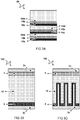
- FIG 2A-D schematically depict cross-section views of four embodiments of solid state electrolytes 10 wherein one or more of the hereinabove described features are incorporated.
- FIG 2A depicts an exemplary embodiment of the solid state electrolyte 10, wherein two opposing faces of the ion conductive matrix 10m are provided with hybrid layers 10h1 and 10h2 having differing thicknesses z1 and z2.
- FIG 2B depicts an exemplary embodiment of the solid state electrolyte 10 wherein two opposing faces of the ion conductive matrix 10m are provided with hybrid layers and wherein one of the faces of the solid state electrolyte 10 is further provided with a ceramic capping layer 10c.
- FIG 2C depicts an exemplary embodiment of the solid state electrolyte 10 comprising a capping layer and a hybrid layer on a first face and a second capping layer 10c at the opposing face of the solid state electrolyte 10.
- FIG 2D depicts an exemplary embodiment of the solid state electrolyte 10 wherein the hybrid layer in infiltrated over the complete thickness of the ion conductive matrix and wherein the infiltrated ion conductive matrix 10m is further provided with first and second capping layers 10c1, 10c2 on opposing faces. It will be appreciated that the depicted exemplary embodiments are not to be understood as limiting examples.
- the invention further relates to solid state electrolytes 10 comprising different or further combinations of ion conductive matrices, hybrid layers, and ceramic capping layers.
- the ion conductive matrix 10m may be provided with a first ceramic capping at the face for connecting with a negative electrode material (anode) and may be impregnated with a second ceramic material at a face for interfacing with a positive electrode material (cathode).
- the ion conductive matrix 10m may be provided with a first ceramic capping at a face for connecting with a positive electrode material (cathode) and impregnated with a second ceramic material at a face for interfacing with a negative electrode material (anode).
- the solid electrolyte 10 comprises capping layers at both faces of the ion conductive matrix 10m for connecting to the electrodes.
- the one or more hybrid layers and one or more capping layers may be formed using same ceramic materials.
- the ceramic materials comprised in the hybrid and/or capping layers may selected independently.
- the conductive and interface properties of the formed solid state electrolyte may be optimized independently. For example, a first ceramic material may be selected to impregnate the ion conductive matrix 10m, whereas a second, possibly different, ceramic material may be selected for optimal mechanical properties and/or optimal contact resistance at an interface with an electrode material.
- the disclose further relates to a multi-layered solid state electrolyte 20.
- the multi-layered solid state electrolyte may be formed by a stack of two or more of the solid state electrolyte layers 10 according to the invention.
- the multi-layered solid state electrolyte comprises a three ion conductive matrices 10m, 11m, and 12m, three hybrid layers 10h, 11h, and 12h, and three capping layers 10c, 11c, and 12c.
- the multi-layered solid state electrolyte 20 is not limited to the embodiment as shown. Other stacks formed from two or more of any of the solid state electrolytes 10 as described herein as envisioned as well.
- a battery 102 is formed with an essentially 2D layered architecture.
- the exemplary 2D battery stack is depicted in a cross section view and comprises a negative electrode layer 2 connected to a current collector 2c; a positive electrode layer 3 connected to a current collected 3c; and a solid state electrolyte 10 according any of the solid state electrolytes 10 describe herein.
- the process for the manufacturing of the solid state electrolyte 10 according to the invention may also be compatible with manufacturing processes of 3D batteries.
- a 3D battery typically comprises a structured current collector formed of a base structure comprising an array of conductive elements spaced at a distance from one another and extending in a direction away from said base.
- these elements further functional layers, e.g. electrode, and/or electrolyte, are provided, preferably in a conformal way such that the 3D cell comprises a larger interface area between functional layers, and may provide larger currents, than a corresponding 2D cell.
- the present disclosure further relates to a battery 103 comprising a 3D-current collector structure, wherein at least one electrode material largely follows the 3D-structure.
- more of the layers in the stack follow the 3D-structure at least partially.
- FIG 3C depicts a cross-section view of a 3D battery comprising a negative electrode layer 2 connected to a 3D structured current collector 2c; a positive electrode layer 3 connected to a current collected 3c; and a solid state electrolyte 10 according any of the solid state electrolytes according to the invention.
- the battery comprises: a negative electrode comprising metal lithium, a metal salt comprising lithium ions.
- the solid state electrolyte 10 may be provided with a ceramic coating comprising a lithiophilic material.
- aspects of the present disclosure further relate to a process for the manufacture of solid state electrolytes.
- the manufacturing process comprises obtaining an ion conductive matrix 10m comprising a polymer P and a metal salt S dispersed in the ion conductive matrix.
- the ion conductive matrix 10m may be obtained in the form of a film wherein the film may be provided on a carrier substrate or alternatively, the ion conductive matrix may be provided as a free-standing film.
- the process for the manufacture of the disclosed solid state electrolytes further comprises feeding the ion conductive matrix 10m to a station for impregnating the layer with a ceramic material. In a preferred embodiment, impregnating may be performed by chemical vapor infiltration.
- Chemical vapor infiltration comprises exposing a face of the ion conductive matrix 10m with a vapor phase ceramic precursor material.
- the vapor phase ceramic precursor material infiltrates into the ion conductive matrix 10m, and reacts with a co-reactant to form a hybrid layer.
- the ceramic precursor material infiltrates the ion conductive matrix 10m across the whole thickness of the matrix forming a hybrid layer that extends over the complete thickness of the ion conductive matrix 10m.
- Suitable ceramic precursor materials typically comprise metalorganic compounds with low vapor pressure.
- Suitable co-reactants may be selected from a group consisting of water, H 2 S, and oxidizing plasma. The co-reactant may also be provided in the gas phase.
- the ion conductive matrix 10m may be provided on a substrate.
- the solid state electrolyte 10 may be manufactured using a free standing ion conductive matrix 10m film.
- the manufacturing process of the solid state electrolyte 10 may be integrated into a manufacturing process of a battery comprising the solid state electrolyte 10 according to any of the preceding claims.
- the substrate may comprise one or more of a current collector and an electrode material, e.g. an intermediate product during a layer-by-layer production process of a layered battery.
- the infiltration process is performed using a chemical vapor deposition process such as, chemical vapor deposition (CVD), physical vapor deposition (PVD) and atomic layer deposition (ALD) or spatially resolved version of thereof (sALD) or a gas-phase reaction within the matrix.
- CVD chemical vapor deposition
- PVD physical vapor deposition
- ALD atomic layer deposition
- sALD spatially resolved version of thereof
- the infiltration process may be performed using wet-chemical processes.
- the ceramic precursor material and/or co-reactants are added in a time or spatially resolved way. By providing the ceramic precursor material and/or co-reactants in a time resolved or spatially resolved way, control over the reaction process, e.g. the amount and infiltration depth of formed ceramic material, may be obtained.
- fabrication of the solid state electrolyte (10) may advantageously be integrated into a roll-to-roll production process.
- one or more of the aspects (i-vi) allow for formation of the hybrid layer: (i) by exposing a face of the ion conductive matrix 10m to a ceramic precursor material, e.g., a vapor phase ceramic precursor material, said precursor material may infiltrate, e.g.
- a ceramic precursor material e.g., a vapor phase ceramic precursor material
- said co-reactant may also be provided in the vapor phase in which case it may also penetrate the ion conductive matrix 10m; (vi) by providing the ceramic precursor material and co-reaction in a time and/or spatially resolved way control may be obtained over the amount and/or penetration depth of said reactants into the ion conductive matrix 10m.
- the amount of vapor phase ceramic precursor material that impregnates the ion conductive matrix 10m and the depth it impregnates into the matrix may be controlled by one or more of the exposure concentration and/or pressure, exposure temperature, exposure time and delay time between consecutive exposures. For example, increasing the exposure concentration, pressure, and/or time may increase the amount of formed ceramic. Increasing the delay between consecutive exposures may increase the time the precursor material can diffuse down into the ion conductive matrix 10m before reacting with a co-reactant, thus increasing the impregnation depth. Increased exposure temperature increases diffusion speed and may accordingly increase impregnation depth. In some preferred embodiments water is the intended co-reactant.
- the ceramic precursor material may react to form a hybrid layer using water that may be dispersed throughout the ion conductive matrix 10m.
- the polymer P comprised in the ion conductive matrix 10m is typically a polyether type polymer which take up water well.
- Incorporated water may be remnant from a formation or deposition process of said ion conductive matrix 10m.
- the amount of water dispersed throughout the matrix may be controlled by application of one or more of a pressure and temperature gradient. In other words, suitable amounts of water may be provided to the matrix by controlled partial drying of a wet ion conductive matrix 10m.
- the infiltration depth of the ceramic precursor material may be controlled. For example, by partially depleting water from the matrix near its surface, ceramic vapors may diffuse further down into the bulk of the matrix before reacting with water, or in other words, increasing the thickness of the hybrid layer. By increasing the amount of water throughout the matrix may cause reactive vapors to react closer to the surface, thus reducing the infiltration depth, or in other words, reducing the thickness of the hybrid layer.
- the process further comprises providing one or more ceramic capping layers. Said ceramic material may be formed from a reaction between a suitable ceramic precursor material and a co-reactant.
- said reactants are provided using chemical vapor deposition process such as CVD, PVD, ALD, and sALD.
- reactants may be provided by wet chemical techniques including, but not limited to: spray coating, e.g. spray coating of nanoparticles.
- forming of the hybrid layer and the ceramic capping layer may be performed using the same tool, e.g. using the same process.
- the capping layer may be formed using a different vapor deposition method.
- the capping layer maybe formed from a different ceramic material.
- further capping layers may be provided onto the formed capping layer.
- one or more of: the ion conductive hybrid layer formation, and the capping layer formation are also performed on a second face of the ion conductive matrix 10m.
- the process further comprises depositing an electrode material.
- the process may be integrated into a process for the manufacturing of a battery. Accordingly, following the formation of the solid state electrolyte 10, the process may comprise deposition of a positive electrode material onto the solid state electrolyte 10. Alternatively, a negative electrode material may be deposited following the formation of the solid state electrolyte 10.
Landscapes
- Chemical & Material Sciences (AREA)
- Engineering & Computer Science (AREA)
- General Chemical & Material Sciences (AREA)
- Chemical Kinetics & Catalysis (AREA)
- Electrochemistry (AREA)
- Manufacturing & Machinery (AREA)
- Inorganic Chemistry (AREA)
- Physics & Mathematics (AREA)
- Condensed Matter Physics & Semiconductors (AREA)
- General Physics & Mathematics (AREA)
- Materials Engineering (AREA)
- Dispersion Chemistry (AREA)
- Ceramic Engineering (AREA)
- Composite Materials (AREA)
- Secondary Cells (AREA)
- Battery Electrode And Active Subsutance (AREA)
- Conductive Materials (AREA)
Priority Applications (7)
| Application Number | Priority Date | Filing Date | Title |
|---|---|---|---|
| EP18214047.5A EP3671930A1 (fr) | 2018-12-19 | 2018-12-19 | Électrolyte hybride à semi-conducteur |
| US17/414,645 US12368185B2 (en) | 2018-12-19 | 2019-12-19 | Hybrid solid state electrolyte |
| JP2021533286A JP7641221B2 (ja) | 2018-12-19 | 2019-12-19 | ハイブリッド固体電解質 |
| CN201980085785.8A CN113228369B (zh) | 2018-12-19 | 2019-12-19 | 混合固态电解质 |
| PCT/NL2019/050856 WO2020130822A1 (fr) | 2018-12-19 | 2019-12-19 | Électrolyte à l'état solide hybride |
| EP19831932.9A EP3900096A1 (fr) | 2018-12-19 | 2019-12-19 | Électrolyte à l'état solide hybride |
| JP2024155384A JP2025000665A (ja) | 2018-12-19 | 2024-09-09 | ハイブリッド固体電解質 |
Applications Claiming Priority (1)
| Application Number | Priority Date | Filing Date | Title |
|---|---|---|---|
| EP18214047.5A EP3671930A1 (fr) | 2018-12-19 | 2018-12-19 | Électrolyte hybride à semi-conducteur |
Publications (1)
| Publication Number | Publication Date |
|---|---|
| EP3671930A1 true EP3671930A1 (fr) | 2020-06-24 |
Family
ID=64746169
Family Applications (2)
| Application Number | Title | Priority Date | Filing Date |
|---|---|---|---|
| EP18214047.5A Withdrawn EP3671930A1 (fr) | 2018-12-19 | 2018-12-19 | Électrolyte hybride à semi-conducteur |
| EP19831932.9A Pending EP3900096A1 (fr) | 2018-12-19 | 2019-12-19 | Électrolyte à l'état solide hybride |
Family Applications After (1)
| Application Number | Title | Priority Date | Filing Date |
|---|---|---|---|
| EP19831932.9A Pending EP3900096A1 (fr) | 2018-12-19 | 2019-12-19 | Électrolyte à l'état solide hybride |
Country Status (5)
| Country | Link |
|---|---|
| US (1) | US12368185B2 (fr) |
| EP (2) | EP3671930A1 (fr) |
| JP (2) | JP7641221B2 (fr) |
| CN (1) | CN113228369B (fr) |
| WO (1) | WO2020130822A1 (fr) |
Families Citing this family (6)
| Publication number | Priority date | Publication date | Assignee | Title |
|---|---|---|---|---|
| CN110690391B (zh) * | 2019-10-12 | 2022-04-22 | 福建师范大学 | 高安全隔膜的涂覆方法 |
| US11721801B2 (en) * | 2020-08-17 | 2023-08-08 | International Business Machines Corporation, Armonk | Low resistance composite silicon-based electrode |
| CN113193227B (zh) * | 2021-04-26 | 2024-07-30 | 上海科技大学 | 一种通过气相渗透法改性的固态电解质聚合物的制备方法及其应用 |
| CN113327769A (zh) * | 2021-06-01 | 2021-08-31 | 吴永德 | 基于巨介电陶瓷材料的长效储能电容器 |
| WO2023097474A1 (fr) * | 2021-11-30 | 2023-06-08 | 宁德时代新能源科技股份有限公司 | Batterie secondaire, module de batterie, bloc-batterie et dispositif électrique |
| CN115472442B (zh) * | 2022-09-15 | 2023-05-16 | 西湖大学 | 一种基于电解质的自定义结构储能器件及其制备方法 |
Citations (3)
| Publication number | Priority date | Publication date | Assignee | Title |
|---|---|---|---|---|
| EP1598896A1 (fr) * | 2004-04-24 | 2005-11-23 | Electronics and Telecommunications Research Institute | Électrolyte à composite polymère contenant une charge inorganique conductrice d'ions lithium pour une battérie secondaire au lithium et méthode de fabrication d'un tel électrolyte |
| KR20170102001A (ko) * | 2015-01-09 | 2017-09-06 | 어플라이드 머티어리얼스, 인코포레이티드 | 배터리 세퍼레이터들 상의 리튬 금속 코팅 |
| US20180026302A1 (en) | 2016-07-20 | 2018-01-25 | University Of Dayton | High-performance ceramic-polymer separators for lithium batteries |
Family Cites Families (17)
| Publication number | Priority date | Publication date | Assignee | Title |
|---|---|---|---|---|
| CA2268316C (fr) | 1999-04-07 | 2003-09-23 | Hydro-Quebec | Composite enduction lipo3 |
| US6645675B1 (en) * | 1999-09-02 | 2003-11-11 | Lithium Power Technologies, Inc. | Solid polymer electrolytes |
| KR100496642B1 (ko) * | 2003-04-25 | 2005-06-20 | 한국전자통신연구원 | 단이온 전도체를 포함하는 리튬 이차전지용 복합 고분자전해질 및 그 제조 방법 |
| JP5153065B2 (ja) * | 2005-08-31 | 2013-02-27 | 株式会社オハラ | リチウムイオン二次電池および固体電解質 |
| CA2552282A1 (fr) | 2006-07-18 | 2008-01-18 | Hydro Quebec | Materiau multi-couches a base de lithium vif, procedes de preparation et applications dans les generateurs electrochimiques |
| JP5211527B2 (ja) * | 2007-03-29 | 2013-06-12 | Tdk株式会社 | 全固体リチウムイオン二次電池及びその製造方法 |
| CA2820635A1 (fr) | 2013-06-21 | 2014-12-21 | Hydro-Quebec | Cellules electrochimiques polymere li-s a l'etat solide et leurs procedes de fabrication |
| JP6607871B2 (ja) * | 2015-02-12 | 2019-11-20 | 富士フイルム株式会社 | 全固体二次電池、それに用いる固体電解質組成物、これを用いた電池用電極シート、ならびに電池用電極シートおよび全固体二次電池の製造方法 |
| JP2016219130A (ja) * | 2015-05-15 | 2016-12-22 | セイコーエプソン株式会社 | 固体電解質電池、電極複合体、複合固体電解質および固体電解質電池の製造方法 |
| JP6757797B2 (ja) * | 2015-12-28 | 2020-09-23 | シーオ インコーポレーテッドSeeo, Inc. | リチウムポリマー電池用セラミック‐ポリマー複合電解質 |
| KR20170111439A (ko) * | 2016-03-28 | 2017-10-12 | 주식회사 세븐킹에너지 | 다층 구조를 가지는 이차전지용 복합 전해질 |
| WO2018027477A1 (fr) * | 2016-08-08 | 2018-02-15 | 肖飞 | Composé de carbonate de polyéthylène glycol d'indolone spirocyclique, composition, procédé de préparation et utilisation de ceux-ci |
| CN106784966B (zh) * | 2016-12-07 | 2019-10-01 | 中国科学院化学研究所 | 一类低界面电阻、高机械强度全固态电池的制备方法及应用 |
| CN107834104B (zh) * | 2017-12-12 | 2020-08-21 | 清陶(昆山)能源发展有限公司 | 一种复合固态电解质及其制备方法以及在全固态锂电池中的应用 |
| CN108598560B (zh) * | 2018-02-27 | 2020-02-21 | 北京匠芯电池科技有限公司 | 复合固体电解质及其制备方法和应用 |
| CN108963317B (zh) * | 2018-07-13 | 2020-03-27 | 东莞塔菲尔新能源科技有限公司 | 一种混合型全固态电池 |
| CN109004271B (zh) * | 2018-08-01 | 2020-09-15 | 惠州亿纬锂能股份有限公司 | 一种复合固态电解质膜及其制备方法和用途 |
-
2018
- 2018-12-19 EP EP18214047.5A patent/EP3671930A1/fr not_active Withdrawn
-
2019
- 2019-12-19 EP EP19831932.9A patent/EP3900096A1/fr active Pending
- 2019-12-19 WO PCT/NL2019/050856 patent/WO2020130822A1/fr not_active Ceased
- 2019-12-19 US US17/414,645 patent/US12368185B2/en active Active
- 2019-12-19 CN CN201980085785.8A patent/CN113228369B/zh active Active
- 2019-12-19 JP JP2021533286A patent/JP7641221B2/ja active Active
-
2024
- 2024-09-09 JP JP2024155384A patent/JP2025000665A/ja active Pending
Patent Citations (3)
| Publication number | Priority date | Publication date | Assignee | Title |
|---|---|---|---|---|
| EP1598896A1 (fr) * | 2004-04-24 | 2005-11-23 | Electronics and Telecommunications Research Institute | Électrolyte à composite polymère contenant une charge inorganique conductrice d'ions lithium pour une battérie secondaire au lithium et méthode de fabrication d'un tel électrolyte |
| KR20170102001A (ko) * | 2015-01-09 | 2017-09-06 | 어플라이드 머티어리얼스, 인코포레이티드 | 배터리 세퍼레이터들 상의 리튬 금속 코팅 |
| US20180026302A1 (en) | 2016-07-20 | 2018-01-25 | University Of Dayton | High-performance ceramic-polymer separators for lithium batteries |
Non-Patent Citations (1)
| Title |
|---|
| S. ZEKLOLL ET AL., ENERGY & ENVIRONMENTAL SCIENCE, vol. 11, 2018, pages 185 - 201 |
Also Published As
| Publication number | Publication date |
|---|---|
| JP2022512217A (ja) | 2022-02-02 |
| WO2020130822A1 (fr) | 2020-06-25 |
| JP2025000665A (ja) | 2025-01-07 |
| CN113228369B (zh) | 2025-04-18 |
| US12368185B2 (en) | 2025-07-22 |
| JP7641221B2 (ja) | 2025-03-06 |
| US20220052378A1 (en) | 2022-02-17 |
| CN113228369A (zh) | 2021-08-06 |
| EP3900096A1 (fr) | 2021-10-27 |
Similar Documents
| Publication | Publication Date | Title |
|---|---|---|
| Jiang et al. | Reducing the interfacial resistance in all‐solid‐state lithium batteries based on oxide ceramic electrolytes | |
| US10700377B2 (en) | Solid electrolyte for a negative electrode of a secondary battery including first and second solid electrolytes with different affinities for metal deposition electronchemical cell and method of manufacturing | |
| US10840513B2 (en) | Solid electrolyte for a negative electrode of a secondary battery and methods for the manufacture of an electrochemical cell | |
| US12368185B2 (en) | Hybrid solid state electrolyte | |
| US20200335818A1 (en) | Porous Ceramic Fibers for Electrolyte Support and Processing | |
| JP7048846B2 (ja) | リチウム電極、この製造方法及びこれを含むリチウム二次電池 | |
| KR102378583B1 (ko) | 리튬-함유 복합체의 코팅층을 구비한 세퍼레이터, 이를 포함하는 리튬 이차전지 및 상기 이차전지의 제조방법 | |
| KR20210048607A (ko) | 애노드 활성 물질, 캐소드 활성 물질, 및 고체-상태 전해질에 대한 나노-엔지니어링된 코팅 및 나노-엔지니어링된 코팅을 함유하는 배터리의 제조 방법 | |
| EP4310938A2 (fr) | Anode pour batterie au lithium-métal, batterie au lithium-métal comprenant une anode et procédé de fabrication d'anode pour batterie au lithium-métal | |
| CN108028383A (zh) | 用于电池组单元的经涂覆的阴极活性材料 | |
| CN105190969A (zh) | 用于电极的保护结构 | |
| CN109565019A (zh) | 隔膜和包含该隔膜的锂硫电池 | |
| EP4024503A1 (fr) | Batterie secondaire au lithium | |
| CN114497449A (zh) | 用于快速充电的电极架构 | |
| CN111211291A (zh) | 具有均匀的沉积行为的复合电极 | |
| US20240030501A1 (en) | Electrochemical cells including anodes comprising a protective layer, and related methods | |
| Raja et al. | High performance multi-functional trilayer membranes as permselective separators for lithium–sulfur batteries | |
| KR102543245B1 (ko) | 리튬 전극, 이의 제조방법 및 이를 포함하는 리튬 이차전지 | |
| KR20190042671A (ko) | 리튬이온 배터리용 전극 재료 | |
| JP2024533465A (ja) | 高電圧リチウム含有電気化学セルおよび関連方法 | |
| KR102881954B1 (ko) | 이온 전도성이 있는 엣지부재를 적용한 무음극 전고체 전지 및 이의 제조방법 | |
| KR102903847B1 (ko) | 음극 및 이를 포함하는 리튬전지 | |
| US20200388854A1 (en) | Cermet electrode for solid state and lithium ion batteries | |
| KR20210037358A (ko) | 전고체 전지용 전극 및 이를 포함하는 전고체 전지 | |
| US20240322169A1 (en) | Anode and lithium battery including the anode |
Legal Events
| Date | Code | Title | Description |
|---|---|---|---|
| PUAI | Public reference made under article 153(3) epc to a published international application that has entered the european phase |
Free format text: ORIGINAL CODE: 0009012 |
|
| STAA | Information on the status of an ep patent application or granted ep patent |
Free format text: STATUS: THE APPLICATION HAS BEEN PUBLISHED |
|
| AK | Designated contracting states |
Kind code of ref document: A1 Designated state(s): AL AT BE BG CH CY CZ DE DK EE ES FI FR GB GR HR HU IE IS IT LI LT LU LV MC MK MT NL NO PL PT RO RS SE SI SK SM TR |
|
| AX | Request for extension of the european patent |
Extension state: BA ME |
|
| STAA | Information on the status of an ep patent application or granted ep patent |
Free format text: STATUS: THE APPLICATION IS DEEMED TO BE WITHDRAWN |
|
| 18D | Application deemed to be withdrawn |
Effective date: 20210112 |