EP3671936A2 - Lithium metal secondary battery and battery module including same - Google Patents
Lithium metal secondary battery and battery module including same Download PDFInfo
- Publication number
- EP3671936A2 EP3671936A2 EP19751730.3A EP19751730A EP3671936A2 EP 3671936 A2 EP3671936 A2 EP 3671936A2 EP 19751730 A EP19751730 A EP 19751730A EP 3671936 A2 EP3671936 A2 EP 3671936A2
- Authority
- EP
- European Patent Office
- Prior art keywords
- secondary battery
- lithium metal
- metal secondary
- negative electrode
- battery
- Prior art date
- Legal status (The legal status is an assumption and is not a legal conclusion. Google has not performed a legal analysis and makes no representation as to the accuracy of the status listed.)
- Granted
Links
Images

Classifications
-
- H—ELECTRICITY
- H01—ELECTRIC ELEMENTS
- H01M—PROCESSES OR MEANS, e.g. BATTERIES, FOR THE DIRECT CONVERSION OF CHEMICAL ENERGY INTO ELECTRICAL ENERGY
- H01M10/00—Secondary cells; Manufacture thereof
- H01M10/42—Methods or arrangements for servicing or maintenance of secondary cells or secondary half-cells
- H01M10/44—Methods for charging or discharging
-
- H—ELECTRICITY
- H01—ELECTRIC ELEMENTS
- H01M—PROCESSES OR MEANS, e.g. BATTERIES, FOR THE DIRECT CONVERSION OF CHEMICAL ENERGY INTO ELECTRICAL ENERGY
- H01M10/00—Secondary cells; Manufacture thereof
- H01M10/04—Construction or manufacture in general
- H01M10/0468—Compression means for stacks of electrodes and separators
-
- H—ELECTRICITY
- H01—ELECTRIC ELEMENTS
- H01M—PROCESSES OR MEANS, e.g. BATTERIES, FOR THE DIRECT CONVERSION OF CHEMICAL ENERGY INTO ELECTRICAL ENERGY
- H01M10/00—Secondary cells; Manufacture thereof
- H01M10/05—Accumulators with non-aqueous electrolyte
- H01M10/052—Li-accumulators
-
- H—ELECTRICITY
- H01—ELECTRIC ELEMENTS
- H01M—PROCESSES OR MEANS, e.g. BATTERIES, FOR THE DIRECT CONVERSION OF CHEMICAL ENERGY INTO ELECTRICAL ENERGY
- H01M10/00—Secondary cells; Manufacture thereof
- H01M10/05—Accumulators with non-aqueous electrolyte
- H01M10/058—Construction or manufacture
-
- H—ELECTRICITY
- H01—ELECTRIC ELEMENTS
- H01M—PROCESSES OR MEANS, e.g. BATTERIES, FOR THE DIRECT CONVERSION OF CHEMICAL ENERGY INTO ELECTRICAL ENERGY
- H01M4/00—Electrodes
- H01M4/02—Electrodes composed of, or comprising, active material
- H01M4/04—Processes of manufacture in general
- H01M4/043—Processes of manufacture in general involving compressing or compaction
-
- H—ELECTRICITY
- H01—ELECTRIC ELEMENTS
- H01M—PROCESSES OR MEANS, e.g. BATTERIES, FOR THE DIRECT CONVERSION OF CHEMICAL ENERGY INTO ELECTRICAL ENERGY
- H01M4/00—Electrodes
- H01M4/02—Electrodes composed of, or comprising, active material
- H01M4/04—Processes of manufacture in general
- H01M4/0438—Processes of manufacture in general by electrochemical processing
- H01M4/044—Activating, forming or electrochemical attack of the supporting material
- H01M4/0445—Forming after manufacture of the electrode, e.g. first charge, cycling
- H01M4/0447—Forming after manufacture of the electrode, e.g. first charge, cycling of complete cells or cells stacks
-
- H—ELECTRICITY
- H01—ELECTRIC ELEMENTS
- H01M—PROCESSES OR MEANS, e.g. BATTERIES, FOR THE DIRECT CONVERSION OF CHEMICAL ENERGY INTO ELECTRICAL ENERGY
- H01M4/00—Electrodes
- H01M4/02—Electrodes composed of, or comprising, active material
- H01M4/13—Electrodes for accumulators with non-aqueous electrolyte, e.g. for lithium-accumulators; Processes of manufacture thereof
- H01M4/134—Electrodes based on metals, Si or alloys
-
- H—ELECTRICITY
- H01—ELECTRIC ELEMENTS
- H01M—PROCESSES OR MEANS, e.g. BATTERIES, FOR THE DIRECT CONVERSION OF CHEMICAL ENERGY INTO ELECTRICAL ENERGY
- H01M4/00—Electrodes
- H01M4/02—Electrodes composed of, or comprising, active material
- H01M4/36—Selection of substances as active materials, active masses, active liquids
- H01M4/38—Selection of substances as active materials, active masses, active liquids of elements or alloys
- H01M4/381—Alkaline or alkaline earth metals elements
- H01M4/382—Lithium
-
- H—ELECTRICITY
- H01—ELECTRIC ELEMENTS
- H01M—PROCESSES OR MEANS, e.g. BATTERIES, FOR THE DIRECT CONVERSION OF CHEMICAL ENERGY INTO ELECTRICAL ENERGY
- H01M50/00—Constructional details or processes of manufacture of the non-active parts of electrochemical cells other than fuel cells, e.g. hybrid cells
- H01M50/10—Primary casings; Jackets or wrappings
- H01M50/102—Primary casings; Jackets or wrappings characterised by their shape or physical structure
- H01M50/105—Pouches or flexible bags
-
- H—ELECTRICITY
- H01—ELECTRIC ELEMENTS
- H01M—PROCESSES OR MEANS, e.g. BATTERIES, FOR THE DIRECT CONVERSION OF CHEMICAL ENERGY INTO ELECTRICAL ENERGY
- H01M50/00—Constructional details or processes of manufacture of the non-active parts of electrochemical cells other than fuel cells, e.g. hybrid cells
- H01M50/20—Mountings; Secondary casings or frames; Racks, modules or packs; Suspension devices; Shock absorbers; Transport or carrying devices; Holders
- H01M50/204—Racks, modules or packs for multiple batteries or multiple cells
- H01M50/207—Racks, modules or packs for multiple batteries or multiple cells characterised by their shape
- H01M50/211—Racks, modules or packs for multiple batteries or multiple cells characterised by their shape adapted for pouch cells
-
- H—ELECTRICITY
- H01—ELECTRIC ELEMENTS
- H01M—PROCESSES OR MEANS, e.g. BATTERIES, FOR THE DIRECT CONVERSION OF CHEMICAL ENERGY INTO ELECTRICAL ENERGY
- H01M50/00—Constructional details or processes of manufacture of the non-active parts of electrochemical cells other than fuel cells, e.g. hybrid cells
- H01M50/20—Mountings; Secondary casings or frames; Racks, modules or packs; Suspension devices; Shock absorbers; Transport or carrying devices; Holders
- H01M50/218—Mountings; Secondary casings or frames; Racks, modules or packs; Suspension devices; Shock absorbers; Transport or carrying devices; Holders characterised by the material
- H01M50/22—Mountings; Secondary casings or frames; Racks, modules or packs; Suspension devices; Shock absorbers; Transport or carrying devices; Holders characterised by the material of the casings or racks
- H01M50/227—Organic material
-
- Y—GENERAL TAGGING OF NEW TECHNOLOGICAL DEVELOPMENTS; GENERAL TAGGING OF CROSS-SECTIONAL TECHNOLOGIES SPANNING OVER SEVERAL SECTIONS OF THE IPC; TECHNICAL SUBJECTS COVERED BY FORMER USPC CROSS-REFERENCE ART COLLECTIONS [XRACs] AND DIGESTS
- Y02—TECHNOLOGIES OR APPLICATIONS FOR MITIGATION OR ADAPTATION AGAINST CLIMATE CHANGE
- Y02E—REDUCTION OF GREENHOUSE GAS [GHG] EMISSIONS, RELATED TO ENERGY GENERATION, TRANSMISSION OR DISTRIBUTION
- Y02E60/00—Enabling technologies; Technologies with a potential or indirect contribution to GHG emissions mitigation
- Y02E60/10—Energy storage using batteries
-
- Y—GENERAL TAGGING OF NEW TECHNOLOGICAL DEVELOPMENTS; GENERAL TAGGING OF CROSS-SECTIONAL TECHNOLOGIES SPANNING OVER SEVERAL SECTIONS OF THE IPC; TECHNICAL SUBJECTS COVERED BY FORMER USPC CROSS-REFERENCE ART COLLECTIONS [XRACs] AND DIGESTS
- Y02—TECHNOLOGIES OR APPLICATIONS FOR MITIGATION OR ADAPTATION AGAINST CLIMATE CHANGE
- Y02P—CLIMATE CHANGE MITIGATION TECHNOLOGIES IN THE PRODUCTION OR PROCESSING OF GOODS
- Y02P70/00—Climate change mitigation technologies in the production process for final industrial or consumer products
- Y02P70/50—Manufacturing or production processes characterised by the final manufactured product
Definitions
- the present disclosure relates to a lithium metal secondary battery and a battery module including the same. More particularly, the present disclosure relates to a lithium metal secondary battery having improved cycle characteristics and a battery module including the same.
- lithium metal secondary battery using lithium metal or lithium alloy as a negative electrode having high energy density has been given many attentions.
- a lithium metal secondary battery refers to a secondary battery using lithium metal or a lithium alloy as a negative electrode.
- Lithium metal has a low density of 0.54 g/cm 3 and a significantly low standard reduction potential of -3.045V (SHE: based on the standard hydrogen electrode), and thus has been most spotlighted as an electrode material for a high-energy density battery.
- Such a lithium metal secondary battery has not been commercialized due to its poor cycle characteristics. This is because dendritic plating of lithium occurs during charge to cause an increase in surface area of an electrode and side reactions with an electrolyte.
- the present disclosure is directed to providing a lithium metal secondary battery which can provide improved cycle characteristics by applying a predetermined pressure during charge to prevent dendritic plating of lithium physically, and a battery module including the same.
- a lithium metal secondary battery according to any one of the following embodiments.
- a lithium metal secondary battery which includes:
- the lithium metal secondary battery according to the first embodiment wherein the pressure applied during charge is 3-150 psi.
- the lithium metal secondary battery according to the first or the second embodiment wherein the pressure applied during charge is 40-100 psi.
- the lithium metal secondary battery according to the first to the third embodiments wherein the pressure applied during discharge is 1-10 psi, when the lithium metal secondary battery is discharged under a pressurized state.
- the lithium metal secondary battery according to the first to the fourth embodiments wherein the current density during charge is 0.01-4 mA/cm 2 .
- the lithium metal secondary battery according to the first to the fifth embodiments wherein the current density during charge is 0.05-3.5 mA/cm 2 .
- the lithium metal secondary battery according to the first to the sixth embodiments wherein the temperature during charge is 25-45°C.
- the lithium metal secondary battery according to the first to the seventh embodiments which is charged at a temperature of 25-45°C under a pressure of 40-100 psi with a charging current density of 0.05-3.5 mA/cm 2 , and is discharged under a non-pressurized state or under a pressure of 1-10 psi.
- the lithium metal secondary battery according to the first to the eighth embodiments which is a pouch-type lithium metal secondary battery.
- a battery module according to any one of the following embodiments.
- a battery module including a plurality of unit cells and a module casing for receiving the unit cells, wherein the unit cell is the lithium metal secondary battery as defined in any one of the first to the ninth embodiments.
- the battery module as defined in the tenth embodiment, wherein the lithium metal secondary battery is a pouch-type lithium metal secondary battery.
- the battery module as defined in the tenth or the eleventh embodiment, wherein the module casing includes a rubber material.
- the battery module as defined in any one of the tenth to the twelfth embodiments, wherein a portion of the module casing that is in contact with the large-area surface of the unit cell includes a rubber material.
- a battery pack including the battery module as defined in the tenth embodiment.
- the lithium metal secondary battery is charged under a pressurized state and discharged under a non-pressurized state or pressurized state.
- a pressurized state and discharged under a non-pressurized state or pressurized state.
- pressure is applied merely during charge and pressure may not be applied or a predetermined level of pressure may be applied during discharge. Therefore, it is possible to provide higher efficiency as compared to charge/discharge under pressure application.
- the lithium metal secondary battery includes: an electrode assembly including a negative electrode, a positive electrode and a separator interposed between the negative electrode and the positive electrode; a non-aqueous electrolyte with which the electrode assembly is impregnated; and a battery casing in which the electrode assembly and the non-aqueous electrolyte are received, wherein the negative electrode includes a negative electrode current collector and a lithium metal layer formed on at least one surface of the negative electrode current collector, the charge/discharge condition of the lithium metal secondary battery includes charging the lithium metal secondary battery under a pressurized state and discharging the lithium metal secondary battery under a non-pressurized or pressurized state, and when the lithium secondary battery is discharged under a pressurized state, the pressure applied during discharge is controlled to be smaller than the pressure applied during charge.
- the lithium metal secondary battery according to the present disclosure is subjected to a controlled charge/discharge condition so that it is charged under pressurization using a pressurization device to inhibit swelling of its appearance, and is discharged without pressurization (under a non-pressurized state) or under a pressurized state with a pressure smaller than the pressure applied during charge.
- the lithium metal secondary battery according to the present disclosure is not subjected to pressure application at all times, but is subjected to pressure application merely during the charge of the battery and is not subjected to pressure application during the discharge of the battery. Otherwise, the lithium metal secondary battery is subjected to pressure application during charge of the battery and is also subjected to application of a predetermined range of pressure during discharge of the battery. Thus, undesired pressure is not used during discharge to provide convenience of use. Otherwise, the charge/discharge condition is controlled to apply lower pressure during discharge as compared to the pressure applied during charge. As a result, when both electrodes are spaced from each other undesirably due to a swelling phenomenon after the completion of charge cycles, it is possible to compress them to reinforce the contact between both electrodes, and thus to improve battery performance.
- 'pressurize a lithium metal secondary battery' or 'pressure is applied to a lithium metal secondary battery' means that pressure is applied in the thickness direction of the lithium metal secondary battery or to the large-area surface thereof.
- the pressure applied during charge of the lithium metal secondary battery may be 3-150 psi, or 40-100 psi.
- the pressure applied during charge is within the above-defined range, it is possible to effectively prevent dendritic plating of lithium occurring during charge, and to avoid leakage of a non-aqueous electrolyte, an increase in cell resistance and compression of a separator, caused by excessive pressurization, thereby ensuring cell safety.
- the pressure applied during discharge may be 1-10 psi, or 5-10 psi.
- the pressure applied during discharge is within the above-defined range, it is possible to minimize a space between both electrodes, and thus to reduce cell resistance.
- pressurization to the lithium metal secondary battery may be carried out through a charger provided with a pressurization device (pressure application device).
- the charger provided with a pressurization device may include a pressurization device formed integrally with a charger, or a conventional charger to which a pressurization device is linked.
- the charger provided with a pressurization device may include: a storage member in which a secondary battery cell is received; a pressurization member facing the storage member with the secondary battery cell interposed therebetween, and spaced apart from the storage member with a variable distance; a pressurization means configured to pressurize the secondary battery cell received in the storage member, in the thickness direction of the secondary battery cell by pushing or pulling the pressurization member toward or from the storage member; a measuring means configured to measure the pressure applied to the pressurization member and/or the distance between the storage member and the pressurization member at a predetermined time interval; a controlling unit configured to receive the values of the pressure applied to the pressurization member and the distance between the storage member and the pressurization member at a predetermined time interval, and to maintain the distance constantly or to change the distance in order to keep the pressure constant.; and a charging unit configured to charge the secondary battery cell received in the storage member.
- Pressurization modes of the lithium metal secondary battery during charge/discharge thereof may be classified into a constant-pressure pressurization mode, constant-distance pressurization mode and a combined constant-pressure/constant-distance pressurization mode, depending on the pressure-controlling mode in the charger provided with the pressurization means.
- the pressure applied to the pressurization member is maintained constantly.
- the distance between the storage member and the pressurization member is maintained constantly.
- the pressure and the distance are controlled simultaneously or sequentially.
- the distance between the storage member and the pressurization member is maintained constantly.
- higher pressure may be applied to the lithium metal secondary battery.
- pressure fixed by the pressurization means is applied to the lithium metal secondary battery, and thus the distance between the storage member and the pressurization member may be changed during the pressurization.
- the optimum voltage range may be slightly higher as compared to the constant-distance pressurization mode.
- the lithium metal secondary battery when the lithium metal secondary battery is discharged under a non-pressurized state, the lithium metal secondary battery may be removed from the charger after completing charge under a pressurized state with the charger provided with a pressurization means, or the pressure of the charger may be controlled to 0 psi.
- the pressure applied to the lithium metal secondary battery may be controlled to be lower than the pressure applied during charge, after completing charge under a pressurized state with the charger provided with a pressurization means.
- the current density during charge may be 0.01-4 mA/cm 2 , or 0.05-3.5 mA/cm 2 .
- the current density during charge is within the above-defined range, delocalization of current is reduced and lithium plating is formed evenly to prevent deterioration of the battery.
- the temperature during charge is 25-45°C.
- activation energy for chemical energy is satisfied to reduce resistance, and thus to improve capacity maintenance.
- the lithium metal secondary battery may be charged at a temperature of 25-45°C under a pressure of 40-100 psi with a charging current density of 0.05-3.5 mA/cm 2 , and may be discharged under a non-pressurized state or under a pressure of 1-10 psi.
- the negative electrode includes a negative electrode current collector and a lithium metal layer formed on the negative electrode current collector.
- the lithium metal layer is a sheet-like metal and may have a width controllable depending on electrode shape to facilitate manufacture of an electrode.
- the lithium metal layer may have a thickness of 0-300 ⁇ m.
- 'lithium metal layer having a thickness of 0 ⁇ m' means that no lithium metal layer is formed on the negative electrode current collector right after the assemblage of the lithium metal secondary battery. Even when no lithium metal layer is formed on the negative electrode current collector, lithium ions are transported from the positive electrode, during charge, to produce a lithium metal layer on the surface of the negative electrode current collector. Therefore, it is possible to operate the lithium metal secondary battery.
- non-limiting examples of the negative electrode current collector include foil made of copper, gold, nickel, copper alloy or a combination thereof.
- the positive electrode may include a positive electrode current collector and a positive electrode active material layer coated on either surface or both surfaces thereof.
- the positive electrode current collector include foil made of aluminum, nickel or a combination thereof.
- the positive electrode active material contained in the positive electrode active material layer may be any one selected from the group consisting of LiCoO 2 , LiNiO 2 , LiMn 2 O 4 , LiCoPO 4 , LiFePO 4 , LiNi 1/3 Mn 1/3 Co 1/3 O 2 , LiNi 1-x-y-z Co x M1 y M2 z O 2 (wherein each of M1 and M2 independently represents any one selected from the group consisting of Al, Ni, Co, Fe, Mn, V, Cr, Ti, W, Ta, Mg and Mo, each of x, y and z independently represents the atomic ratio of an element forming oxide, and 0 ⁇ x ⁇ 0.5, 0 ⁇ y ⁇ 0.5, 0 ⁇ z ⁇ 0.5, and 0
- the positive electrode active material layer may further include a conductive material to improve electrical conductivity.
- the conductive material is not particularly limited, as long as it is an electrically conductive material causing no chemical change in the lithium metal secondary battery.
- carbon black, graphite, carbon fibers, carbon nanotubes, metal powder, conductive metal oxide or an organic conductive material may be used.
- Commercially available products of such conductive materials include acetylene black (available from Chevron Chemical Company or Gulf Oil Company), Ketjen Black EC series (available from Armak Company), Vulcan XC-72 (available from Cabot Company) and Super P (available from MMM Company).
- acetylene black, carbon black or graphite may be used.
- binders which serve to retain the positive electrode active material on the positive electrode current collector and to interconnect active material particles may be used.
- binders include polyvinylidene fluoride-co-hexafluoroprpylene (PVDF-co-HFP), polyvinylidene fluoride (PVDF), polymethyl methacrylate, styrene butadiene rubber (SBR), carboxymethyl cellulose (CMC), or the like.
- the separator may include a porous polymer substrate.
- the porous polymer substrate may be any porous polymer substrate used conventionally for a lithium secondary battery, and particular examples thereof include a polyolefin-based porous membrane or non-woven web but are not limited thereto.
- polystyrene-based porous membrane may include those formed of polymers including polyethylene, such as high-density polyethylene, linear low-density polyethylene, low-density polyethylene and ultrahigh-molecular weight polyethylene, polypropylene, polybutylene and polypentene, alone or in combination.
- polyethylene such as high-density polyethylene, linear low-density polyethylene, low-density polyethylene and ultrahigh-molecular weight polyethylene, polypropylene, polybutylene and polypentene, alone or in combination.
- non-woven web may include those formed of polymers including polyethylene terephthalate, polybutylene terephthalate, polyester, polyacetal, polyamide, polycarbonate, polyimide, polyether ether ketone, polyether sulfone, polyphenylene oxide, polyether sulfone, polyphenylene oxide, polyphenylene sulfide, polyethylene naphthalene, or the like, alone or in combination.
- the non-woven web structure may be a spun-bonded non-woven web including long fibers or a melt blown non-woven web.
- the thickness of the porous polymer substrate is not particularly limited but may be 1-100 ⁇ m, or 5-50 ⁇ m.
- the size of pores and the porosity present in the porous polymer substrate are not particularly limited.
- the pore size and porosity may be 0.001-50 ⁇ m and 10-95%, respectively.
- the electrolyte salt contained in the non-aqueous electrolyte that may be used in the present disclosure is a lithium salt.
- Any lithium salt used conventionally for an electrolyte for a lithium secondary battery may be used without particular limitation.
- the anion of the lithium salt may be any one selected from the group consisting of F - , Cl - , Br - , I - , NO 3 - , N(CN) 2 - , BF 4 - , ClO 4 - , PF 6 - , (CF 3 ) 2 PF 4 - , (CF 3 ) 3 PF 3 - , (CF 3 ) 4 PF 2 - , (CF 3 ) 5 PF - , (CF 3 ) 6 P - , CF 3 SO 3 - , CF 3 CF 2 SO 3 - , (CF 3 SO 2 ) 2 N - , (FSO 2 ) 2 N - , CF 3 CF 2 (CF 3 )
- organic solvent for example, it is possible to use ethers, esters, amides, linear carbonates or cyclic carbonates, alone or in combination.
- Typical examples of the organic solvent may include carbonate compounds, such as cyclic carbonates, linear carbonates or mixtures thereof.
- cyclic carbonate compounds include any one selected from the group consisting of ethylene carbonate (EC), propylene carbonate (PC), 1,2-butylene carbonate, 2,3-butylene carbonate, 1,2-pentylene carbonate, 2,3-pentylene carbonate, vinylene carbonate, halides thereof, and combinations thereof.
- halides include fluoroethylene carbonate (FEC) but are not limited thereto.
- linear carbonate compounds include any one selected from the group consisting of dimethyl carbonate (DMC), diethyl carbonate (DEC), dipropyl carbonate, ethyl methyl carbonate (EMC), methyl propyl carbonate, ethyl propyl carbonate and combinations thereof, but are not limited thereto.
- ethylene carbonate and propylene carbonate which are cyclic carbonates among the carbonate organic solvents, have a high dielectric constant and dissociate the lithium salt in an electrolyte well.
- ethers may include any one selected from the group consisting of dimethyl ether, diethyl ether, dipropyl ether, methyl ethyl ether, methyl propyl ether, ethyl propyl ether, and combinations thereof, but are not limited thereto.
- esters include any one selected from the group consisting of methyl acetate, ethyl acetate, propyl acetate, methyl propionate, ethyl propionate, ⁇ -butyrolactone, ⁇ -valerolactone, ⁇ -caprolactone, ⁇ -valerolactone, ⁇ -caprolactone and combinations thereof, but are not limited thereto.
- Injection of the non-aqueous electrolyte may be carried out in an adequate step during the process for manufacturing a lithium secondary battery depending on the manufacturing process of a final product and properties required for a final product. In other words, injection of the non-aqueous electrolyte may be carried out before the assemblage of a lithium secondary battery or in the final step of the assemblage of a lithium secondary battery.
- the lithium secondary battery according to the present disclosure may be subjected to a lamination or stacking step of a separator with electrodes and a folding step, in addition to the conventional winding step.
- the battery casing may have a cylindrical, prismatic, pouch-like or coin-like shape.
- the lithium metal secondary battery may be a cylindrical-type lithium metal secondary battery, a prismatic-type lithium metal secondary battery, a pouch-type lithium metal secondary battery or a coin-type lithium metal secondary battery, particularly a pouch-type lithium metal secondary battery.
- the battery module according to the present disclosure includes a plurality of unit cells and a module casing in which the unit cells are received, wherein the unit cell is the above-defined lithium metal secondary battery.
- the battery module may include two or more pouch-type unit cells and a module casing in which the pouch-type unit cells are received, wherein the module casing may include a rubber material.
- the pouch-type lithium metal secondary battery according to the present disclosure undergoes an increase in volume during charge and a decrease in volume during discharge. Pressurization during charge can prevent a significant increase in volume according to the present disclosure. However, such an increase in volume cannot be prevented perfectly. In addition, a decrease in volume during discharge is inevitable.
- the module casing may include a rubber material in order to alleviate an increase/decrease in volume during charge/discharge of the unit cells.
- the module casing may totally include a rubber material, or only a portion that is in contact with the large-area surface of the unit cell may include a rubber material.
- a battery pack including the battery module and a device including the battery pack as a power source.
- particular examples of the device may include, but are not limited to: power tools driven by an electric motor; electric cars, including electric vehicles (EV), hybrid electric vehicles (HEV), plug-in hybrid electric vehicles (PHEV), or the like; electric carts, including electric bikes (E-bike) and electric scooters (E-scooter); electric golf carts; electric power storage systems; or the like.
- electric motor including electric vehicles (EV), hybrid electric vehicles (HEV), plug-in hybrid electric vehicles (PHEV), or the like
- electric carts including electric bikes (E-bike) and electric scooters (E-scooter)
- electric golf carts including electric power storage systems; or the like.
- Lithium metal foil having a thickness of 20 ⁇ m was attached to one surface of a copper current collector having a thickness of 10 ⁇ m to obtain a negative electrode.
- a separator (polyethylene-based porous polymer substrate having porous coating layers containing a mixture of alumina with PVDF binder on both surfaces thereof) was interposed between the positive electrode and the negative electrode to form an electrode assembly.
- the electrode assembly was inserted to a pouch-type battery casing.
- an electrolyte including 1 wt% of vinylene carbonate (VC) as an additive and 1M LiPF 6 dissolved in a solvent containing fluoroethylene carbonate (FEC) mixed with ethyl methyl carbonate (EMC) at a volume ratio of 30:70 was injected to the battery casing. After that, the battery casing was sealed completely to obtain a lithium metal secondary battery.
- the lithium metal secondary battery was charged to 4.25V under a constant-current/constant-voltage (CC/CV) condition and discharged (discharge temperature 25°C) to 3V under a constant-current (CC) condition with a current density of 2 mA/cm 2 , while varying the pressurization condition during charge/discharge as shown in the following Table 1.
- CC/CV constant-current/constant-voltage
- CC constant-current
- the lithium metal secondary battery was charged/discharged by using a charger to which a constant-pressure pressurization device is linked.
- the pressurization device includes: a storage member in which a secondary battery cell is received; a pressurization member facing the storage member with the secondary cell interposed therebetween, and spaced apart from the storage member with a variable distance; a pressurization means configured to pressurize the secondary battery cell received in the storage member, in the thickness direction of the secondary battery cell by pushing or pulling the pressurization member toward or from the storage member; a measuring means configured to measure the pressure applied to the pressurization member and/or the distance between the storage member and the pressurization member at a predetermined time interval; and a controlling unit configured to receive the values of the pressure applied to the pressurization member and the distance between the storage member and the pressurization member at a predetermined time interval, and to maintain the distance constantly or to change the distance in order to keep the pressure constant.
- the lithium metal secondary battery was mounted to the pressurization device. Then, the lithium metal secondary battery was connected to a charger (PNE Solution Co., PESC05), and charge/discharge was carried out under the condition as shown in Table 1.
- the pressure applied to the lithium secondary battery during charge/discharge was controlled through the pressurization device.
- the pressurization condition during charge means the pressure (pressurization force) applied to the lithium metal secondary battery during charge
- the pressurization condition during discharge means the pressure (pressurization force) applied to the lithium metal secondary battery during discharge.
- Comparative Examples 1-4 wherein no pressurization is applied during charge of the lithium metal secondary battery, provide a capacity maintenance of 0 after 50 cycles, while Examples, wherein pressurization is applied during charge, show a capacity maintenance of at least 15%.
- Examples 9-23 wherein pressurization is applied during charge with a pressure of 40 psi and 100 psi, show a high capacity maintenance of at least 64%.
- Example 10 Example 18 and Example 19 wherein charge/discharge is carried out under the same pressurization condition, temperature and current density during charge, and the different pressurization condition of 0, 5 and 10 psi during discharge, it can be seen that they show an equivalent capacity maintenance of 75-79%.
- the lithium metal secondary battery according to the present disclosure satisfies the pressurization condition during charge, it is possible to provide improved cycle characteristics by preventing dendritic plating of lithium physically, even though discharge is carried out without pressurization (in a non-pressurized state) or under application of a pressure lower than the pressure applied during charge.
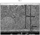
- FIG. 1 is a scanning electron microscopic (SEM) image illustrating the sectional view of the negative electrode after repeating 10 cycles in the lithium metal secondary battery according to Comparative Example 1.
- FIG. 2 is an SEM image illustrating the sectional view of the negative electrode after repeating 10 cycles in the lithium metal secondary battery according to Example 5.
- lithium metal grows like dendrite to form pores.
- copper foil having a thickness of 13 ⁇ m, lithium metal having a thickness of 13.8 ⁇ m and dendrite having a thickness of 236 ⁇ m are observed, when viewed from the bottom.
- FIG. 2 illustrating the negative electrode according to Example 5 it can be seen that the dendrite layer has a smaller thickness, no pores are formed, and the lithium metal layer has a larger thickness.
- the lithium metal secondary battery according to the present disclosure can prevent dendritic plating of lithium physically by carrying out charge under a pressurized condition and discharge under a non-pressurized state or pressurized state.
Landscapes
- Chemical & Material Sciences (AREA)
- Chemical Kinetics & Catalysis (AREA)
- Electrochemistry (AREA)
- General Chemical & Material Sciences (AREA)
- Engineering & Computer Science (AREA)
- Manufacturing & Machinery (AREA)
- Materials Engineering (AREA)
- Secondary Cells (AREA)
- Battery Mounting, Suspending (AREA)
Abstract
Description
- The present disclosure relates to a lithium metal secondary battery and a battery module including the same. More particularly, the present disclosure relates to a lithium metal secondary battery having improved cycle characteristics and a battery module including the same.
- The present application claims priority to Korean Patent Application No.
10-2018-0015293 filed on February 7, 2018 - As electric, electronic, communication and computer industries have been developed rapidly, high-capacity batteries have been in increasingly in demand. To meet such demand, a lithium metal secondary battery using lithium metal or lithium alloy as a negative electrode having high energy density has been given many attentions.
- A lithium metal secondary battery refers to a secondary battery using lithium metal or a lithium alloy as a negative electrode. Lithium metal has a low density of 0.54 g/cm3 and a significantly low standard reduction potential of -3.045V (SHE: based on the standard hydrogen electrode), and thus has been most spotlighted as an electrode material for a high-energy density battery.
- Such a lithium metal secondary battery has not been commercialized due to its poor cycle characteristics. This is because dendritic plating of lithium occurs during charge to cause an increase in surface area of an electrode and side reactions with an electrolyte.
- Therefore, there is a need for a method for preventing dendritic plating of lithium physically.
- The present disclosure is directed to providing a lithium metal secondary battery which can provide improved cycle characteristics by applying a predetermined pressure during charge to prevent dendritic plating of lithium physically, and a battery module including the same.
- In one aspect of the present disclosure, there is provided a lithium metal secondary battery according to any one of the following embodiments.
- According to the first embodiment, there is provided a lithium metal secondary battery which includes:
- an electrode assembly including a negative electrode, a positive electrode and a separator interposed between the negative electrode and the positive electrode;
- a non-aqueous electrolyte with which the electrode assembly is impregnated; and
- a battery casing in which the electrode assembly and the non-aqueous electrolyte are received,
- wherein the negative electrode includes a negative electrode current collector and a lithium metal layer formed on at least one surface of the negative electrode current collector,
- the charge/discharge condition of the lithium metal secondary battery includes charging the lithium metal secondary battery under a pressurized state and discharging the lithium metal secondary battery under a non-pressurized or pressurized state, and
- when the lithium secondary battery is discharged under a pressurized state, the pressure applied during discharge is controlled to be smaller than the pressure applied during charge.
- According to the second embodiment, there is provided the lithium metal secondary battery according to the first embodiment, wherein the pressure applied during charge is 3-150 psi.
- According to the third embodiment, there is provided the lithium metal secondary battery according to the first or the second embodiment, wherein the pressure applied during charge is 40-100 psi.
- According to the fourth embodiment, there is provided the lithium metal secondary battery according to the first to the third embodiments, wherein the pressure applied during discharge is 1-10 psi, when the lithium metal secondary battery is discharged under a pressurized state.
- According to the fifth embodiment, there is provided the lithium metal secondary battery according to the first to the fourth embodiments, wherein the current density during charge is 0.01-4 mA/cm2.
- According to the sixth embodiment, there is provided the lithium metal secondary battery according to the first to the fifth embodiments, wherein the current density during charge is 0.05-3.5 mA/cm2.
- According to the seventh embodiment, there is provided the lithium metal secondary battery according to the first to the sixth embodiments, wherein the temperature during charge is 25-45°C.
- According to the eighth embodiment, there is provided the lithium metal secondary battery according to the first to the seventh embodiments, which is charged at a temperature of 25-45°C under a pressure of 40-100 psi with a charging current density of 0.05-3.5 mA/cm2, and is discharged under a non-pressurized state or under a pressure of 1-10 psi.
- According to the ninth embodiment, there is provided the lithium metal secondary battery according to the first to the eighth embodiments, which is a pouch-type lithium metal secondary battery.
- In another aspect of the present disclosure, there is provided a battery module according to any one of the following embodiments.
- According to the tenth embodiment, there is provided a battery module including a plurality of unit cells and a module casing for receiving the unit cells, wherein the unit cell is the lithium metal secondary battery as defined in any one of the first to the ninth embodiments.
- According to the eleventh embodiment, there is provided the battery module as defined in the tenth embodiment, wherein the lithium metal secondary battery is a pouch-type lithium metal secondary battery.
- According to the twelfth embodiment, there is provided the battery module as defined in the tenth or the eleventh embodiment, wherein the module casing includes a rubber material.
- According to the thirteenth embodiment, there is provided the battery module as defined in any one of the tenth to the twelfth embodiments, wherein a portion of the module casing that is in contact with the large-area surface of the unit cell includes a rubber material.
- In still another aspect, there is provided the battery pack according to the following embodiment.
- According to the fourteenth embodiment, there is provided a battery pack including the battery module as defined in the tenth embodiment.
- According to the present disclosure, the lithium metal secondary battery is charged under a pressurized state and discharged under a non-pressurized state or pressurized state. Thus, it is possible to physically prevent dendritic plating of lithium occurring during charge, and thus to improve cycle characteristics of the battery.
- In addition, pressure is applied merely during charge and pressure may not be applied or a predetermined level of pressure may be applied during discharge. Therefore, it is possible to provide higher efficiency as compared to charge/discharge under pressure application.
- The accompanying drawings illustrate a preferred embodiment of the present disclosure and together with the foregoing disclosure, serve to provide further understanding of the technical features of the present disclosure, and thus, the present disclosure is not construed as being limited to the drawing.
-
FIG. 1 is a scanning electron microscopic (SEM) image illustrating the sectional view of the negative electrode after repeating cycles in the lithium metal secondary battery according to Comparative Example 1. -
FIG. 2 is an SEM image illustrating the sectional view of the negative electrode after repeating cycles in the lithium metal secondary battery according to Example 5. - Hereinafter, preferred embodiments of the present disclosure will be described in detail with reference to the accompanying drawings. Prior to the description, it should be understood that the terms used in the specification and the appended claims should not be construed as limited to general and dictionary meanings, but interpreted based on the meanings and concepts corresponding to technical aspects of the present disclosure on the basis of the principle that the inventor is allowed to define terms appropriately for the best explanation.
- Therefore, the description proposed herein is just a preferable example for the purpose of illustrations only, not intended to limit the scope of the disclosure, so it should be understood that other equivalents and modifications could be made thereto without departing from the scope of the disclosure.
- The lithium metal secondary battery according to an embodiment of the present disclosure includes: an electrode assembly including a negative electrode, a positive electrode and a separator interposed between the negative electrode and the positive electrode; a non-aqueous electrolyte with which the electrode assembly is impregnated; and a battery casing in which the electrode assembly and the non-aqueous electrolyte are received, wherein the negative electrode includes a negative electrode current collector and a lithium metal layer formed on at least one surface of the negative electrode current collector, the charge/discharge condition of the lithium metal secondary battery includes charging the lithium metal secondary battery under a pressurized state and discharging the lithium metal secondary battery under a non-pressurized or pressurized state, and when the lithium secondary battery is discharged under a pressurized state, the pressure applied during discharge is controlled to be smaller than the pressure applied during charge. In the conventional lithium metal secondary battery, dendritic plating of lithium is formed on the negative electrode surface during charge. As a result, there are problems in that charge capacity is decreased due to an increase in distance between the negative electrode and the positive electrode, or deformation occurs repeatedly due to charge/discharge to cause deterioration of internal elements and degradation of cycle life.
- To improve the above-mentioned problems, the lithium metal secondary battery according to the present disclosure is subjected to a controlled charge/discharge condition so that it is charged under pressurization using a pressurization device to inhibit swelling of its appearance, and is discharged without pressurization (under a non-pressurized state) or under a pressurized state with a pressure smaller than the pressure applied during charge.
- According to the present disclosure, it is possible to physically prevent dendritic plating of lithium, which may be generated during the charge of a lithium metal secondary battery, by carrying out charge under a pressurized state. It is also possible to inhibit side reactions with an electrolyte caused by an increase in surface area of an electrode due to dendritic plating of lithium, and thus to improve cycle characteristics of the battery.
- Further, the lithium metal secondary battery according to the present disclosure is not subjected to pressure application at all times, but is subjected to pressure application merely during the charge of the battery and is not subjected to pressure application during the discharge of the battery. Otherwise, the lithium metal secondary battery is subjected to pressure application during charge of the battery and is also subjected to application of a predetermined range of pressure during discharge of the battery. Thus, undesired pressure is not used during discharge to provide convenience of use. Otherwise, the charge/discharge condition is controlled to apply lower pressure during discharge as compared to the pressure applied during charge. As a result, when both electrodes are spaced from each other undesirably due to a swelling phenomenon after the completion of charge cycles, it is possible to compress them to reinforce the contact between both electrodes, and thus to improve battery performance.
- As used herein, 'pressurize a lithium metal secondary battery' or 'pressure is applied to a lithium metal secondary battery' means that pressure is applied in the thickness direction of the lithium metal secondary battery or to the large-area surface thereof.
- According to an embodiment of the present disclosure, the pressure applied during charge of the lithium metal secondary battery may be 3-150 psi, or 40-100 psi. When the pressure applied during charge is within the above-defined range, it is possible to effectively prevent dendritic plating of lithium occurring during charge, and to avoid leakage of a non-aqueous electrolyte, an increase in cell resistance and compression of a separator, caused by excessive pressurization, thereby ensuring cell safety.
- When the lithium metal secondary battery is discharged under a pressurized state, the pressure applied during discharge may be 1-10 psi, or 5-10 psi. When the pressure applied during discharge is within the above-defined range, it is possible to minimize a space between both electrodes, and thus to reduce cell resistance.
- Meanwhile, pressurization to the lithium metal secondary battery may be carried out through a charger provided with a pressurization device (pressure application device). Herein, the charger provided with a pressurization device may include a pressurization device formed integrally with a charger, or a conventional charger to which a pressurization device is linked.
- According to an embodiment of the present disclosure, the charger provided with a pressurization device may include: a storage member in which a secondary battery cell is received; a pressurization member facing the storage member with the secondary battery cell interposed therebetween, and spaced apart from the storage member with a variable distance; a pressurization means configured to pressurize the secondary battery cell received in the storage member, in the thickness direction of the secondary battery cell by pushing or pulling the pressurization member toward or from the storage member; a measuring means configured to measure the pressure applied to the pressurization member and/or the distance between the storage member and the pressurization member at a predetermined time interval; a controlling unit configured to receive the values of the pressure applied to the pressurization member and the distance between the storage member and the pressurization member at a predetermined time interval, and to maintain the distance constantly or to change the distance in order to keep the pressure constant.; and a charging unit configured to charge the secondary battery cell received in the storage member. Herein, the storage member, pressurization member, pressurization means, measuring means and the controlling unit form the pressurization device, wherein the charging unit may be formed integrally with the pressurization device or a conventional charger may be linked to the pressurization device.
- Pressurization modes of the lithium metal secondary battery during charge/discharge thereof may be classified into a constant-pressure pressurization mode, constant-distance pressurization mode and a combined constant-pressure/constant-distance pressurization mode, depending on the pressure-controlling mode in the charger provided with the pressurization means.
- In other words, in the constant-pressure pressurization mode, the pressure applied to the pressurization member is maintained constantly. In the constant-distance pressurization mode, the distance between the storage member and the pressurization member is maintained constantly. In the combined constant-pressure/constant-distance pressurization mode, the pressure and the distance are controlled simultaneously or sequentially.
- For example, in the constant-distance pressurization mode, the distance between the storage member and the pressurization member is maintained constantly. Thus, as the lithium metal secondary battery is swelled during charge, higher pressure may be applied to the lithium metal secondary battery. In the constant-pressure pressurization mode, pressure fixed by the pressurization means is applied to the lithium metal secondary battery, and thus the distance between the storage member and the pressurization member may be changed during the pressurization. When using the constant-pressure pressurization mode, the optimum voltage range may be slightly higher as compared to the constant-distance pressurization mode.
- According to an embodiment of the present disclosure, when the lithium metal secondary battery is discharged under a non-pressurized state, the lithium metal secondary battery may be removed from the charger after completing charge under a pressurized state with the charger provided with a pressurization means, or the pressure of the charger may be controlled to 0 psi.
- According to another embodiment of the present disclosure, when the lithium metal secondary battery is discharged under a pressurized state, the pressure applied to the lithium metal secondary battery may be controlled to be lower than the pressure applied during charge, after completing charge under a pressurized state with the charger provided with a pressurization means.
- The current density during charge may be 0.01-4 mA/cm2, or 0.05-3.5 mA/cm2. When the current density during charge is within the above-defined range, delocalization of current is reduced and lithium plating is formed evenly to prevent deterioration of the battery.
- In addition, the temperature during charge is 25-45°C. When the temperature during charge is within the above-defined range, activation energy for chemical energy is satisfied to reduce resistance, and thus to improve capacity maintenance.
- According to an embodiment of the present disclosure, the lithium metal secondary battery may be charged at a temperature of 25-45°C under a pressure of 40-100 psi with a charging current density of 0.05-3.5 mA/cm2, and may be discharged under a non-pressurized state or under a pressure of 1-10 psi.
- In addition, the negative electrode includes a negative electrode current collector and a lithium metal layer formed on the negative electrode current collector. The lithium metal layer is a sheet-like metal and may have a width controllable depending on electrode shape to facilitate manufacture of an electrode. The lithium metal layer may have a thickness of 0-300 µm. Herein, 'lithium metal layer having a thickness of 0 µm' means that no lithium metal layer is formed on the negative electrode current collector right after the assemblage of the lithium metal secondary battery. Even when no lithium metal layer is formed on the negative electrode current collector, lithium ions are transported from the positive electrode, during charge, to produce a lithium metal layer on the surface of the negative electrode current collector. Therefore, it is possible to operate the lithium metal secondary battery.
- Further, non-limiting examples of the negative electrode current collector include foil made of copper, gold, nickel, copper alloy or a combination thereof.
- Meanwhile, the positive electrode may include a positive electrode current collector and a positive electrode active material layer coated on either surface or both surfaces thereof. Herein, non-limiting examples of the positive electrode current collector include foil made of aluminum, nickel or a combination thereof. The positive electrode active material contained in the positive electrode active material layer may be any one selected from the group consisting of LiCoO2, LiNiO2, LiMn2O4, LiCoPO4, LiFePO4, LiNi1/3Mn1/3Co1/3O2, LiNi1-x-y-zCoxM1yM2zO2 (wherein each of M1 and M2 independently represents any one selected from the group consisting of Al, Ni, Co, Fe, Mn, V, Cr, Ti, W, Ta, Mg and Mo, each of x, y and z independently represents the atomic ratio of an element forming oxide, and 0 ≤ x < 0.5, 0 ≤ y < 0.5, 0≤ z < 0.5, and 0 < x + y + z ≤ 1), and combinations thereof.
- In addition, the positive electrode active material layer may further include a conductive material to improve electrical conductivity. Herein, the conductive material is not particularly limited, as long as it is an electrically conductive material causing no chemical change in the lithium metal secondary battery. In general, carbon black, graphite, carbon fibers, carbon nanotubes, metal powder, conductive metal oxide or an organic conductive material may be used. Commercially available products of such conductive materials include acetylene black (available from Chevron Chemical Company or Gulf Oil Company), Ketjen Black EC series (available from Armak Company), Vulcan XC-72 (available from Cabot Company) and Super P (available from MMM Company). For example, acetylene black, carbon black or graphite may be used.
- Further, various types of binders which serve to retain the positive electrode active material on the positive electrode current collector and to interconnect active material particles may be used. Particular examples of such binders include polyvinylidene fluoride-co-hexafluoroprpylene (PVDF-co-HFP), polyvinylidene fluoride (PVDF), polymethyl methacrylate, styrene butadiene rubber (SBR), carboxymethyl cellulose (CMC), or the like.
- In addition, the separator may include a porous polymer substrate. The porous polymer substrate may be any porous polymer substrate used conventionally for a lithium secondary battery, and particular examples thereof include a polyolefin-based porous membrane or non-woven web but are not limited thereto.
- Herein, particular examples of the polyolefin-based porous membrane may include those formed of polymers including polyethylene, such as high-density polyethylene, linear low-density polyethylene, low-density polyethylene and ultrahigh-molecular weight polyethylene, polypropylene, polybutylene and polypentene, alone or in combination.
- In addition to the polyolefin-based non-woven web, particular examples of the non-woven web may include those formed of polymers including polyethylene terephthalate, polybutylene terephthalate, polyester, polyacetal, polyamide, polycarbonate, polyimide, polyether ether ketone, polyether sulfone, polyphenylene oxide, polyether sulfone, polyphenylene oxide, polyphenylene sulfide, polyethylene naphthalene, or the like, alone or in combination. The non-woven web structure may be a spun-bonded non-woven web including long fibers or a melt blown non-woven web.
- The thickness of the porous polymer substrate is not particularly limited but may be 1-100 µm, or 5-50 µm.
- In addition, the size of pores and the porosity present in the porous polymer substrate are not particularly limited. However, the pore size and porosity may be 0.001-50 µm and 10-95%, respectively.
- Further, the electrolyte salt contained in the non-aqueous electrolyte that may be used in the present disclosure is a lithium salt. Any lithium salt used conventionally for an electrolyte for a lithium secondary battery may be used without particular limitation. For example, the anion of the lithium salt may be any one selected from the group consisting of F-, Cl-, Br-, I-, NO3 -, N(CN)2 -, BF4 -, ClO4 -, PF6 -, (CF3)2PF4 -, (CF3)3PF3 -, (CF3)4PF2 -, (CF3)5PF-, (CF3)6P-, CF3SO3 -, CF3CF2SO3 -, (CF3SO2)2N-, (FSO2)2N-, CF3CF2(CF3)2CO-, (CF3SO2)2CH-, (SF5)3C-, (CF3SO2)3C-, CF3(CF2)7SO3 -, CF3CO2 -, CH3CO2 -, SCN-, (CF3CF2SO2)2N-, and combinations thereof.
- Particular examples of the organic solvent that may be contained in the non-aqueous electrolyte may include those used conventionally for an electrolyte for a lithium secondary battery with no particular limitation. For example, it is possible to use ethers, esters, amides, linear carbonates or cyclic carbonates, alone or in combination.
- Typical examples of the organic solvent may include carbonate compounds, such as cyclic carbonates, linear carbonates or mixtures thereof.
- Particular examples of the cyclic carbonate compounds include any one selected from the group consisting of ethylene carbonate (EC), propylene carbonate (PC), 1,2-butylene carbonate, 2,3-butylene carbonate, 1,2-pentylene carbonate, 2,3-pentylene carbonate, vinylene carbonate, halides thereof, and combinations thereof. Particular examples of such halides include fluoroethylene carbonate (FEC) but are not limited thereto.
- In addition, particular examples of the linear carbonate compounds include any one selected from the group consisting of dimethyl carbonate (DMC), diethyl carbonate (DEC), dipropyl carbonate, ethyl methyl carbonate (EMC), methyl propyl carbonate, ethyl propyl carbonate and combinations thereof, but are not limited thereto.
- Particularly, ethylene carbonate and propylene carbonate, which are cyclic carbonates among the carbonate organic solvents, have a high dielectric constant and dissociate the lithium salt in an electrolyte well. In addition, it is possible to prepare an electrolyte having high electrical conductivity, when using such cyclic carbonates in combination with low-viscosity low-dielectric constant linear carbonates, such as dimethyl carbonate and diethyl carbonate, at an adequate ratio.
- Further, among the organic solvents, particular examples of the ethers may include any one selected from the group consisting of dimethyl ether, diethyl ether, dipropyl ether, methyl ethyl ether, methyl propyl ether, ethyl propyl ether, and combinations thereof, but are not limited thereto.
- Among the organic solvents, particular examples of the esters include any one selected from the group consisting of methyl acetate, ethyl acetate, propyl acetate, methyl propionate, ethyl propionate, γ-butyrolactone, γ-valerolactone, γ-caprolactone, σ-valerolactone, ε-caprolactone and combinations thereof, but are not limited thereto.
- Injection of the non-aqueous electrolyte may be carried out in an adequate step during the process for manufacturing a lithium secondary battery depending on the manufacturing process of a final product and properties required for a final product. In other words, injection of the non-aqueous electrolyte may be carried out before the assemblage of a lithium secondary battery or in the final step of the assemblage of a lithium secondary battery.
- The lithium secondary battery according to the present disclosure may be subjected to a lamination or stacking step of a separator with electrodes and a folding step, in addition to the conventional winding step. In addition, the battery casing may have a cylindrical, prismatic, pouch-like or coin-like shape. According to an embodiment of the present disclosure, the lithium metal secondary battery may be a cylindrical-type lithium metal secondary battery, a prismatic-type lithium metal secondary battery, a pouch-type lithium metal secondary battery or a coin-type lithium metal secondary battery, particularly a pouch-type lithium metal secondary battery.
- Meanwhile, the battery module according to the present disclosure includes a plurality of unit cells and a module casing in which the unit cells are received, wherein the unit cell is the above-defined lithium metal secondary battery.
- According to an embodiment of the present disclosure, the battery module may include two or more pouch-type unit cells and a module casing in which the pouch-type unit cells are received, wherein the module casing may include a rubber material.
- The pouch-type lithium metal secondary battery according to the present disclosure undergoes an increase in volume during charge and a decrease in volume during discharge. Pressurization during charge can prevent a significant increase in volume according to the present disclosure. However, such an increase in volume cannot be prevented perfectly. In addition, a decrease in volume during discharge is inevitable.
- According to the present disclosure, the module casing may include a rubber material in order to alleviate an increase/decrease in volume during charge/discharge of the unit cells.
- Herein, the module casing may totally include a rubber material, or only a portion that is in contact with the large-area surface of the unit cell may include a rubber material.
- Meanwhile, in still another aspect, there is provided a battery pack including the battery module and a device including the battery pack as a power source.
- Herein, particular examples of the device may include, but are not limited to: power tools driven by an electric motor; electric cars, including electric vehicles (EV), hybrid electric vehicles (HEV), plug-in hybrid electric vehicles (PHEV), or the like; electric carts, including electric bikes (E-bike) and electric scooters (E-scooter); electric golf carts; electric power storage systems; or the like.
- Examples will be described more fully hereinafter so that the present disclosure can be understood with ease. The following examples may, however, be embodied in many different forms and should not be construed as limited to the exemplary embodiments set forth therein. Rather, these exemplary embodiments are provided so that the present disclosure will be thorough and complete, and will fully convey the scope of the present disclosure to those skilled in the art.
- First, 95 parts by weight of LiNi1/3Mn1/3Co1/3O2 as a positive electrode active material, 2.5 parts by weight of Super P as a conductive material, and 2.5 parts by weight of polyvinylidene fluoride (PVDF) as a binder were added to N-methyl-2-pyrrolidone (NMP) as a solvent to prepare positive electrode active material slurry. Next, the positive electrode active material slurry was coated on one surface of an aluminum current collector to a thickness of 65 µm, followed by drying, pressing and punching into a predetermined size, thereby providing a positive electrode.
- Lithium metal foil having a thickness of 20 µm was attached to one surface of a copper current collector having a thickness of 10 µm to obtain a negative electrode.
- A separator (polyethylene-based porous polymer substrate having porous coating layers containing a mixture of alumina with PVDF binder on both surfaces thereof) was interposed between the positive electrode and the negative electrode to form an electrode assembly. Next, the electrode assembly was inserted to a pouch-type battery casing. Then, an electrolyte including 1 wt% of vinylene carbonate (VC) as an additive and 1M LiPF6 dissolved in a solvent containing fluoroethylene carbonate (FEC) mixed with ethyl methyl carbonate (EMC) at a volume ratio of 30:70 was injected to the battery casing. After that, the battery casing was sealed completely to obtain a lithium metal secondary battery.
- The lithium metal secondary battery was charged to 4.25V under a constant-current/constant-voltage (CC/CV) condition and discharged (discharge temperature 25°C) to 3V under a constant-current (CC) condition with a current density of 2 mA/cm2, while varying the pressurization condition during charge/discharge as shown in the following Table 1. The above-mentioned charge/discharge cycles were repeated 50 times. The capacity maintenance after 50 cycles is shown in Table 1.
- Herein, the lithium metal secondary battery was charged/discharged by using a charger to which a constant-pressure pressurization device is linked.
- Particularly, a pressurization device was prepared. The pressurization device includes: a storage member in which a secondary battery cell is received; a pressurization member facing the storage member with the secondary cell interposed therebetween, and spaced apart from the storage member with a variable distance; a pressurization means configured to pressurize the secondary battery cell received in the storage member, in the thickness direction of the secondary battery cell by pushing or pulling the pressurization member toward or from the storage member; a measuring means configured to measure the pressure applied to the pressurization member and/or the distance between the storage member and the pressurization member at a predetermined time interval; and a controlling unit configured to receive the values of the pressure applied to the pressurization member and the distance between the storage member and the pressurization member at a predetermined time interval, and to maintain the distance constantly or to change the distance in order to keep the pressure constant. The lithium metal secondary battery was mounted to the pressurization device. Then, the lithium metal secondary battery was connected to a charger (PNE Solution Co., PESC05), and charge/discharge was carried out under the condition as shown in Table 1. Herein, the pressure applied to the lithium secondary battery during charge/discharge was controlled through the pressurization device. In Table 1, the pressurization condition during charge means the pressure (pressurization force) applied to the lithium metal secondary battery during charge, and the pressurization condition during discharge means the pressure (pressurization force) applied to the lithium metal secondary battery during discharge.
[Table 1] Charge/Discharge Condition Capacity maintenance after 50 cycles (%) Pressurization condition during charge (psi) Pressurization condition during discharge (psi) Temperature during charge (°C) Current density during charge (mA/cm2) Ex. 1 3 0 25 0.4 20 Ex. 2 2 15 Ex. 3 45 0.4 22 Ex. 4 2 21 Ex. 5 10 25 0.4 40 Ex. 6 2 30 Ex. 7 45 0.4 50 Ex. 8 2 40 Ex. 9 40 25 0.4 77 Ex. 10 2 75 Ex. 11 45 0.4 80 Ex. 12 2 78 Ex. 13 40 25 0.05 80 Ex. 14 0.1 78 Ex. 15 0.4 80 Ex. 16 3 70 Ex. 17 3.5 64 Ex. 18 5 2 79 Ex. 19 10 2 78 Ex. 20 100 0 25 0.4 79 Ex. 21 2 76 Ex. 22 45 0.4 81 Ex. 23 2 80 Ex. 24 150 25 0.4 45 Ex. 25 2 33 Ex. 26 45 0.4 57 Ex. 27 2 47 Comp. Ex. 1 0 25 0.4 0 Comp. Ex. 2 2 0 Comp. Ex. 3 45 0.4 0 Comp. Ex. 4 2 0 - As shown in Table 1, Comparative Examples 1-4, wherein no pressurization is applied during charge of the lithium metal secondary battery, provide a capacity maintenance of 0 after 50 cycles, while Examples, wherein pressurization is applied during charge, show a capacity maintenance of at least 15%.
- Particularly, Examples 9-23, wherein pressurization is applied during charge with a pressure of 40 psi and 100 psi, show a high capacity maintenance of at least 64%.
- In addition, after comparing Example 10, Example 18 and Example 19, wherein charge/discharge is carried out under the same pressurization condition, temperature and current density during charge, and the different pressurization condition of 0, 5 and 10 psi during discharge, it can be seen that they show an equivalent capacity maintenance of 75-79%. This suggests that when the lithium metal secondary battery according to the present disclosure satisfies the pressurization condition during charge, it is possible to provide improved cycle characteristics by preventing dendritic plating of lithium physically, even though discharge is carried out without pressurization (in a non-pressurized state) or under application of a pressure lower than the pressure applied during charge.
- In addition, under the same pressurization condition during charge, a higher capacity maintenance is provided at a higher temperature. Referring to Examples 13-17, it can be seen that capacity maintenance is further improved, when the current density during charge is relatively low within a range of 0.05-2 mA/cm2, under the same pressurization condition and temperature during charge. In other words, when the temperature is higher, activation energy for chemical reaction is satisfied and chemical reaction is accelerated to reduce resistance and to provide slightly increased capacity maintenance. As the current density is decreased, delocalization of electric current is reduced and lithium plating is formed evenly to prevent deterioration of the battery.
-
FIG. 1 is a scanning electron microscopic (SEM) image illustrating the sectional view of the negative electrode after repeating 10 cycles in the lithium metal secondary battery according to Comparative Example 1.FIG. 2 is an SEM image illustrating the sectional view of the negative electrode after repeating 10 cycles in the lithium metal secondary battery according to Example 5. - Referring to
FIG. 1 , in the case of Comparative Example 1, lithium metal grows like dendrite to form pores. In addition, copper foil having a thickness of 13 µm, lithium metal having a thickness of 13.8 µm and dendrite having a thickness of 236 µm are observed, when viewed from the bottom. On the contrary, inFIG. 2 illustrating the negative electrode according to Example 5, it can be seen that the dendrite layer has a smaller thickness, no pores are formed, and the lithium metal layer has a larger thickness. Thus, it can be seen that the lithium metal secondary battery according to the present disclosure can prevent dendritic plating of lithium physically by carrying out charge under a pressurized condition and discharge under a non-pressurized state or pressurized state. - It should be understood that the detailed description are given by way of illustration only and various changes and modifications may be made without departing from the scope of the invention as defined in the following claims. Therefore, the embodiments disclosed herein are not intended to limit the scope of the present disclosure but are for illustrative purposes only, and the scope of the present disclosure is not limited thereto. It should be also understood that the scope of the present disclosure is defined by the following claims and all equivalents thereof are also included in the scope of the present disclosure.
Claims (14)
- A lithium metal secondary battery which comprises:an electrode assembly comprising a negative electrode, a positive electrode and a separator interposed between the negative electrode and the positive electrode;a non-aqueous electrolyte with which the electrode assembly is impregnated; anda battery casing in which the electrode assembly and the non-aqueous electrolyte are received,wherein the negative electrode comprises a negative electrode current collector and a lithium metal layer formed on at least one surface of the negative electrode current collector,the charge/discharge condition of the lithium metal secondary battery comprises charging the lithium metal secondary battery under a pressurized state and discharging the lithium metal secondary battery under a non-pressurized or pressurized state, andwhen the lithium secondary battery is discharged under a pressurized state, the pressure applied during discharge is controlled to be smaller than the pressure applied during charge.
- The lithium metal secondary battery according to claim 1, wherein the pressure applied during charge is 3-150 psi.
- The lithium metal secondary battery according to claim 2, wherein the pressure applied during charge is 40-100 psi.
- The lithium metal secondary battery according to claim 1, wherein the pressure applied during discharge is 1-10 psi, when the lithium metal secondary battery is discharged under a pressurized state.
- The lithium metal secondary battery according to claim 1, wherein the current density during charge is 0.01-4 mA/cm2.
- The lithium metal secondary battery according to claim 1, wherein the current density during charge is 0.05-3.5 mA/cm2.
- The lithium metal secondary battery according to claim 1, wherein the temperature during charge is 25-45°C.
- The lithium metal secondary battery according to claim 1, which is charged at a temperature of 25-45°C under a pressure of 40-100 psi with a charging current density of 0.05-3.5 mA/cm2, and is discharged under a non-pressurized state or under a pressure of 1-10 psi.
- The lithium metal secondary battery according to claim 1, which is a pouch-type lithium metal secondary battery.
- A battery module comprising a plurality of unit cells and a module casing for receiving the unit cells, wherein the unit cell is the lithium metal secondary battery as defined in any one of claims 1 to 9.
- The battery module according to claim 10, wherein the lithium metal secondary battery is a pouch-type lithium metal secondary battery.
- The battery module according to claim 10, wherein the module casing comprises a rubber material.
- The battery module according to claim 10, wherein a portion of the module casing that is in contact with the large-area surface of the unit cell comprises a rubber material.
- A battery pack comprising the battery module as defined in claim 10.
Priority Applications (1)
| Application Number | Priority Date | Filing Date | Title |
|---|---|---|---|
| HUE19751730A HUE070193T2 (en) | 2018-02-07 | 2019-04-05 | Lithium metal secondary battery and battery module including the same |
Applications Claiming Priority (2)
| Application Number | Priority Date | Filing Date | Title |
|---|---|---|---|
| KR20180015293 | 2018-02-07 | ||
| PCT/IB2019/052809 WO2019155452A2 (en) | 2018-02-07 | 2019-04-05 | Lithium metal secondary battery and battery module including same |
Publications (3)
| Publication Number | Publication Date |
|---|---|
| EP3671936A2 true EP3671936A2 (en) | 2020-06-24 |
| EP3671936A4 EP3671936A4 (en) | 2020-12-09 |
| EP3671936B1 EP3671936B1 (en) | 2025-01-22 |
Family
ID=67548848
Family Applications (1)
| Application Number | Title | Priority Date | Filing Date |
|---|---|---|---|
| EP19751730.3A Active EP3671936B1 (en) | 2018-02-07 | 2019-04-05 | Lithium metal secondary battery and battery module including the same |
Country Status (8)
| Country | Link |
|---|---|
| US (1) | US11145889B2 (en) |
| EP (1) | EP3671936B1 (en) |
| JP (1) | JP7267269B2 (en) |
| KR (1) | KR102238829B1 (en) |
| CN (1) | CN112055911B (en) |
| ES (1) | ES3012979T3 (en) |
| HU (1) | HUE070193T2 (en) |
| WO (1) | WO2019155452A2 (en) |
Cited By (1)
| Publication number | Priority date | Publication date | Assignee | Title |
|---|---|---|---|---|
| EP4539202A1 (en) * | 2023-10-10 | 2025-04-16 | Rolls-Royce plc | A battery charging system |
Families Citing this family (11)
| Publication number | Priority date | Publication date | Assignee | Title |
|---|---|---|---|---|
| US11563253B1 (en) * | 2021-07-15 | 2023-01-24 | Enevate Corporation | Method and system for formation of cylindrical and prismatic can cells |
| JP7225961B2 (en) * | 2019-03-14 | 2023-02-21 | トヨタ自動車株式会社 | Secondary battery system |
| EP3998665A4 (en) * | 2019-08-07 | 2022-08-17 | LG Energy Solution, Ltd. | SECONDARY LITHIUM METAL BATTERY AND BATTERY MODULE COMPRISING SUCH BATTERY |
| JP7501110B2 (en) * | 2020-05-26 | 2024-06-18 | 株式会社Gsユアサ | Non-aqueous electrolyte storage element |
| CN111710874B (en) * | 2020-08-19 | 2020-12-08 | 广州纳诺新材料科技有限公司 | Solid-state lithium battery, composite negative electrode and preparation method of composite negative electrode |
| CN113140818B (en) * | 2021-02-27 | 2022-09-06 | 浙江锋锂新能源科技有限公司 | Lithium metal battery pretreatment process and lithium metal battery |
| US20230291061A1 (en) * | 2022-03-08 | 2023-09-14 | Cuberg, Inc. | Battery assemblies comprising lithium-metal electrochemical cells and pressure-applying structures |
| KR102821623B1 (en) | 2022-12-23 | 2025-06-16 | 주식회사 엘지에너지솔루션 | Method for manufacturing lithium secondary battery comprising lithium-rich manganese based oxide |
| EP4683026A2 (en) * | 2023-06-07 | 2026-01-21 | LG Energy Solution, Ltd. | Lithium metal battery, and battery module and battery pack including same |
| WO2025062254A1 (en) * | 2023-09-22 | 2025-03-27 | 株式会社半導体エネルギー研究所 | Secondary battery |
| JP2026064141A (en) * | 2024-10-01 | 2026-04-13 | ソフトバンク株式会社 | Temperature control system, temperature control method, and program |
Family Cites Families (42)
| Publication number | Priority date | Publication date | Assignee | Title |
|---|---|---|---|---|
| JP3184071B2 (en) | 1995-09-06 | 2001-07-09 | キヤノン株式会社 | Lithium secondary battery |
| CA2191019C (en) * | 1996-11-22 | 2001-01-16 | Michel Gauthier | Rechargeable lithium anode for electrolyte polymer battery |
| US6087036A (en) * | 1997-07-25 | 2000-07-11 | 3M Innovative Properties Company | Thermal management system and method for a solid-state energy storing device |
| CN1197190C (en) * | 2000-01-27 | 2005-04-13 | 索尼株式会社 | Manufacturing method of gel electrolyte battery |
| JP2004213902A (en) * | 2002-12-26 | 2004-07-29 | Sony Corp | Battery charging apparatus and battery charging method |
| JP2005032632A (en) * | 2003-07-08 | 2005-02-03 | Hitachi Maxell Ltd | Manufacturing method of non-aqueous secondary battery |
| US10629947B2 (en) * | 2008-08-05 | 2020-04-21 | Sion Power Corporation | Electrochemical cell |
| WO2006064774A1 (en) * | 2004-12-13 | 2006-06-22 | Matsushita Electric Industrial Co., Ltd. | Multilayer body containing active material layer and solid electrolyte layer, and all-solid lithium secondary battery using same |
| JP2008059954A (en) | 2006-08-31 | 2008-03-13 | Seiko Epson Corp | Manufacturing method of secondary battery |
| US9105938B2 (en) * | 2008-08-05 | 2015-08-11 | Sion Power Corporation | Application of force in electrochemical cells |
| KR100918050B1 (en) * | 2007-10-02 | 2009-09-18 | 삼성에스디아이 주식회사 | Anode active material for lithium secondary battery, anode for lithium secondary battery comprising same, and lithium secondary battery |
| US8378045B2 (en) | 2008-12-31 | 2013-02-19 | Dow Global Technologies Llc | Thermoformed article with high stiffness and good optics |
| JP2010225356A (en) * | 2009-03-23 | 2010-10-07 | Sumitomo Electric Ind Ltd | Nonaqueous electrolyte battery and method of using the same |
| US20110300432A1 (en) * | 2010-06-07 | 2011-12-08 | Snyder Shawn W | Rechargeable, High-Density Electrochemical Device |
| EP2721665B1 (en) | 2011-06-17 | 2021-10-27 | Sion Power Corporation | Plating technique for electrode |
| KR101968640B1 (en) | 2012-04-03 | 2019-04-12 | 삼성전자주식회사 | Flexible secondary battery |
| KR20130126365A (en) * | 2012-05-11 | 2013-11-20 | 주식회사 엘지화학 | Manufacturing method of lithium secondary battery |
| US20140234730A1 (en) * | 2013-02-21 | 2014-08-21 | Robert Bosch Gmbh | Metal/Oxygen Battery with Oxygen Pressure Management |
| JP6268866B2 (en) * | 2013-09-25 | 2018-01-31 | 株式会社豊田自動織機 | Method for manufacturing power storage device |
| JP6123642B2 (en) * | 2013-11-08 | 2017-05-10 | トヨタ自動車株式会社 | All-solid battery charging system |
| US20150171398A1 (en) * | 2013-11-18 | 2015-06-18 | California Institute Of Technology | Electrochemical separators with inserted conductive layers |
| JP5954345B2 (en) | 2014-02-20 | 2016-07-20 | トヨタ自動車株式会社 | Method for manufacturing lithium solid state battery module |
| US10193181B2 (en) | 2014-03-17 | 2019-01-29 | Nissan Motor Co., Ltd. | Pressurization device for battery cells |
| JP2016025716A (en) * | 2014-07-18 | 2016-02-08 | 日産自動車株式会社 | Non-aqueous electrolyte secondary battery system |
| JP2016081790A (en) * | 2014-10-20 | 2016-05-16 | トヨタ自動車株式会社 | Manufacturing method of all-solid-state secondary battery |
| JP6448336B2 (en) | 2014-12-04 | 2019-01-09 | 積水化学工業株式会社 | Method for producing lithium ion secondary battery |
| KR101839402B1 (en) * | 2015-04-13 | 2018-04-26 | 주식회사 엘지화학 | Pack Case for Battery Pack Comprising Cell Receiving Portion with Tension Damping Part Formed thereon |
| KR101830286B1 (en) | 2015-05-11 | 2018-02-20 | 주식회사 엘지화학 | Battery Cell Preparation Method Pressurizing Electrode Assembly During Vitalization Process |
| WO2017038041A1 (en) * | 2015-08-28 | 2017-03-09 | パナソニックIpマネジメント株式会社 | Non-aqueous electrolyte secondary battery |
| WO2017077055A1 (en) * | 2015-11-04 | 2017-05-11 | Basf Se | Layer composite and electrode having a smooth surface |
| KR102553471B1 (en) | 2016-02-16 | 2023-07-10 | 에스케이온 주식회사 | Pressing apparatus of bettery cell |
| KR102088272B1 (en) * | 2016-02-26 | 2020-03-12 | 주식회사 엘지화학 | Pressing Device for Battery Cell, Initial Charging and Discharging System for Battery Cell Using the Same, and Method of Initial Charging And Discharging Battery Cell Using the Same |
| WO2017181266A1 (en) * | 2016-04-19 | 2017-10-26 | Blue Solutions Canada Inc. | Pressurized lithium metal polymer battery |
| WO2018075809A1 (en) * | 2016-10-21 | 2018-04-26 | Quantumscape Corporation | Lithium-stuffed garnet electrolytes with a reduced surface defect density and methods of making and using the same |
| US11063299B2 (en) * | 2016-11-16 | 2021-07-13 | Enovix Corporation | Three-dimensional batteries with compressible cathodes |
| CA3046999A1 (en) * | 2016-12-14 | 2018-06-21 | Blue Solutions Canada Inc. | Lithium metal battery containing electrolyte grafted with immobilized anions |
| EP3563445A4 (en) * | 2017-01-02 | 2020-12-09 | 3dbatteries Ltd. | ENERGY STORAGE DEVICES AND SYSTEMS |
| JP2018116914A (en) * | 2017-01-20 | 2018-07-26 | トヨタ自動車株式会社 | Battery module |
| KR102069213B1 (en) * | 2017-01-23 | 2020-01-22 | 주식회사 엘지화학 | Method for preparing lithium secondary battery having high-temperature storage properties |
| KR102518992B1 (en) * | 2017-02-03 | 2023-04-07 | 주식회사 엘지에너지솔루션 | Lithium secondary battery having high-temperature storage properties and method for preparing the same |
| US11735780B2 (en) * | 2017-03-10 | 2023-08-22 | Quantumscape Battery, Inc. | Metal negative electrode ultrasonic charging |
| US10256507B1 (en) * | 2017-11-15 | 2019-04-09 | Enovix Corporation | Constrained electrode assembly |
-
2019
- 2019-02-07 KR KR1020190014610A patent/KR102238829B1/en active Active
- 2019-04-05 ES ES19751730T patent/ES3012979T3/en active Active
- 2019-04-05 CN CN201980004440.5A patent/CN112055911B/en active Active
- 2019-04-05 WO PCT/IB2019/052809 patent/WO2019155452A2/en not_active Ceased
- 2019-04-05 US US16/376,441 patent/US11145889B2/en active Active
- 2019-04-05 JP JP2020520608A patent/JP7267269B2/en active Active
- 2019-04-05 HU HUE19751730A patent/HUE070193T2/en unknown
- 2019-04-05 EP EP19751730.3A patent/EP3671936B1/en active Active
Cited By (1)
| Publication number | Priority date | Publication date | Assignee | Title |
|---|---|---|---|---|
| EP4539202A1 (en) * | 2023-10-10 | 2025-04-16 | Rolls-Royce plc | A battery charging system |
Also Published As
| Publication number | Publication date |
|---|---|
| JP7267269B2 (en) | 2023-05-01 |
| HUE070193T2 (en) | 2025-05-28 |
| WO2019155452A3 (en) | 2019-10-17 |
| EP3671936A4 (en) | 2020-12-09 |
| KR102238829B1 (en) | 2021-04-09 |
| ES3012979T3 (en) | 2025-04-10 |
| CN112055911B (en) | 2025-02-28 |
| US11145889B2 (en) | 2021-10-12 |
| KR20190095904A (en) | 2019-08-16 |
| US20190341647A1 (en) | 2019-11-07 |
| WO2019155452A2 (en) | 2019-08-15 |
| JP2020537309A (en) | 2020-12-17 |
| CN112055911A (en) | 2020-12-08 |
| EP3671936B1 (en) | 2025-01-22 |
Similar Documents
| Publication | Publication Date | Title |
|---|---|---|
| EP3671936B1 (en) | Lithium metal secondary battery and battery module including the same | |
| EP3093914B1 (en) | Method for producing nonaqueous electrolyte secondary cell | |
| EP2942827B1 (en) | Lithium electrode and lithium secondary battery comprising same | |
| KR102518992B1 (en) | Lithium secondary battery having high-temperature storage properties and method for preparing the same | |
| EP3107138B1 (en) | Electrode assembly and lithium battery including the same | |
| EP2942828A1 (en) | Lithium electrode and lithium secondary battery comprising same | |
| KR102420592B1 (en) | Method for preparing negative electrode for lithium secondary battery | |
| KR101799923B1 (en) | Electrode active material slurry for a lithium secondary battery comprise dispersant agent and lithium secondary battery using same | |
| KR20210007273A (en) | Composite anode active material, and Anode and Lithium secondary battery comprising the same | |
| KR102567964B1 (en) | Lithium secondary battery | |
| US20240014392A1 (en) | Positive electrode and lithium secondary battery including the same | |
| KR102279003B1 (en) | Method of manufacturing negative electrode for lithium secondary battery | |
| KR102747621B1 (en) | Method for manufacturing negative electrode | |
| EP4084131A1 (en) | Method for manufacturing anode | |
| EP3998665A1 (en) | Lithium metal secondary battery and battery module comprising same | |
| KR102922363B1 (en) | Electrolyte solution for lithium secondary battery and Lithium secondary battery comprising the same | |
| EP4456246A1 (en) | Electrode for lithium secondary battery, and lithium secondary battery | |
| EP3836264B1 (en) | Electrolyte solution for lithium secondary batteries and lithium secondary battery including the same | |
| KR20220056578A (en) | Electrolyte solution for lithium secondary battery and Lithium secondary battery comprising the same | |
| KR20220048803A (en) | Electrolyte solution for lithium secondary battery and Lithium secondary battery comprising the same | |
| KR102931335B1 (en) | Electrolyte solution for lithium secondary battery and Lithium secondary battery comprising the same | |
| EP3836263A1 (en) | Electrolyte solution for lithium secondary batteries and lithium secondary battery including the same | |
| KR20120118721A (en) | Electrode assembly and electrochemical device comprising the same |
Legal Events
| Date | Code | Title | Description |
|---|---|---|---|
| STAA | Information on the status of an ep patent application or granted ep patent |
Free format text: STATUS: THE INTERNATIONAL PUBLICATION HAS BEEN MADE |
|
| PUAI | Public reference made under article 153(3) epc to a published international application that has entered the european phase |
Free format text: ORIGINAL CODE: 0009012 |
|
| STAA | Information on the status of an ep patent application or granted ep patent |
Free format text: STATUS: REQUEST FOR EXAMINATION WAS MADE |
|
| 17P | Request for examination filed |
Effective date: 20200318 |
|
| AK | Designated contracting states |
Kind code of ref document: A2 Designated state(s): AL AT BE BG CH CY CZ DE DK EE ES FI FR GB GR HR HU IE IS IT LI LT LU LV MC MK MT NL NO PL PT RO RS SE SI SK SM TR |
|
| AX | Request for extension of the european patent |
Extension state: BA ME |
|
| A4 | Supplementary search report drawn up and despatched |
Effective date: 20201105 |
|
| RIC1 | Information provided on ipc code assigned before grant |
Ipc: H01M 10/04 20060101ALI20201030BHEP Ipc: H01M 10/058 20100101AFI20201030BHEP Ipc: H01M 4/134 20100101ALI20201030BHEP Ipc: H01M 2/10 20060101ALI20201030BHEP Ipc: H01M 4/04 20060101ALI20201030BHEP Ipc: H01M 2/02 20060101ALI20201030BHEP Ipc: H01M 10/052 20100101ALI20201030BHEP Ipc: H01M 10/44 20060101ALI20201030BHEP Ipc: H01M 4/38 20060101ALI20201030BHEP |
|
| DAV | Request for validation of the european patent (deleted) | ||
| DAX | Request for extension of the european patent (deleted) | ||
| RAP1 | Party data changed (applicant data changed or rights of an application transferred) |
Owner name: LG ENERGY SOLUTION LTD. |
|
| RAP3 | Party data changed (applicant data changed or rights of an application transferred) |
Owner name: LG ENERGY SOLUTION, LTD. |
|
| STAA | Information on the status of an ep patent application or granted ep patent |
Free format text: STATUS: EXAMINATION IS IN PROGRESS |
|
| 17Q | First examination report despatched |
Effective date: 20231002 |
|
| RIC1 | Information provided on ipc code assigned before grant |
Ipc: H01M 50/227 20210101ALI20240723BHEP Ipc: H01M 50/211 20210101ALI20240723BHEP Ipc: H01M 4/38 20060101ALI20240723BHEP Ipc: H01M 10/44 20060101ALI20240723BHEP Ipc: H01M 4/134 20100101ALI20240723BHEP Ipc: H01M 10/052 20100101ALI20240723BHEP Ipc: H01M 4/04 20060101ALI20240723BHEP Ipc: H01M 10/04 20060101ALI20240723BHEP Ipc: H01M 10/058 20100101AFI20240723BHEP |
|
| GRAP | Despatch of communication of intention to grant a patent |
Free format text: ORIGINAL CODE: EPIDOSNIGR1 |
|
| STAA | Information on the status of an ep patent application or granted ep patent |
Free format text: STATUS: GRANT OF PATENT IS INTENDED |
|
| INTG | Intention to grant announced |
Effective date: 20240924 |
|
| GRAS | Grant fee paid |
Free format text: ORIGINAL CODE: EPIDOSNIGR3 |
|
| P01 | Opt-out of the competence of the unified patent court (upc) registered |
Free format text: CASE NUMBER: APP_60523/2024 Effective date: 20241111 |
|
| GRAA | (expected) grant |
Free format text: ORIGINAL CODE: 0009210 |
|
| STAA | Information on the status of an ep patent application or granted ep patent |
Free format text: STATUS: THE PATENT HAS BEEN GRANTED |
|
| AK | Designated contracting states |
Kind code of ref document: B1 Designated state(s): AL AT BE BG CH CY CZ DE DK EE ES FI FR GB GR HR HU IE IS IT LI LT LU LV MC MK MT NL NO PL PT RO RS SE SI SK SM TR |
|
| REG | Reference to a national code |
Ref country code: GB Ref legal event code: FG4D |
|
| REG | Reference to a national code |
Ref country code: CH Ref legal event code: EP |
|
| REG | Reference to a national code |
Ref country code: IE Ref legal event code: FG4D |
|
| REG | Reference to a national code |
Ref country code: DE Ref legal event code: R096 Ref document number: 602019065102 Country of ref document: DE |
|
| REG | Reference to a national code |
Ref country code: ES Ref legal event code: FG2A Ref document number: 3012979 Country of ref document: ES Kind code of ref document: T3 Effective date: 20250410 |
|
| REG | Reference to a national code |
Ref country code: NL Ref legal event code: MP Effective date: 20250122 Ref country code: HU Ref legal event code: AG4A Ref document number: E070193 Country of ref document: HU |
|
| PG25 | Lapsed in a contracting state [announced via postgrant information from national office to epo] |
Ref country code: NL Free format text: LAPSE BECAUSE OF FAILURE TO SUBMIT A TRANSLATION OF THE DESCRIPTION OR TO PAY THE FEE WITHIN THE PRESCRIBED TIME-LIMIT Effective date: 20250122 |
|
| PG25 | Lapsed in a contracting state [announced via postgrant information from national office to epo] |
Ref country code: RS Free format text: LAPSE BECAUSE OF FAILURE TO SUBMIT A TRANSLATION OF THE DESCRIPTION OR TO PAY THE FEE WITHIN THE PRESCRIBED TIME-LIMIT Effective date: 20250422 |
|
| PG25 | Lapsed in a contracting state [announced via postgrant information from national office to epo] |
Ref country code: FI Free format text: LAPSE BECAUSE OF FAILURE TO SUBMIT A TRANSLATION OF THE DESCRIPTION OR TO PAY THE FEE WITHIN THE PRESCRIBED TIME-LIMIT Effective date: 20250122 |
|
| PG25 | Lapsed in a contracting state [announced via postgrant information from national office to epo] |
Ref country code: PL Free format text: LAPSE BECAUSE OF FAILURE TO SUBMIT A TRANSLATION OF THE DESCRIPTION OR TO PAY THE FEE WITHIN THE PRESCRIBED TIME-LIMIT Effective date: 20250122 |
|
| PGFP | Annual fee paid to national office [announced via postgrant information from national office to epo] |
Ref country code: DE Payment date: 20250320 Year of fee payment: 7 |
|
| PGFP | Annual fee paid to national office [announced via postgrant information from national office to epo] |
Ref country code: ES Payment date: 20250516 Year of fee payment: 7 |
|
| REG | Reference to a national code |
Ref country code: LT Ref legal event code: MG9D |
|
| PG25 | Lapsed in a contracting state [announced via postgrant information from national office to epo] |
Ref country code: NO Free format text: LAPSE BECAUSE OF FAILURE TO SUBMIT A TRANSLATION OF THE DESCRIPTION OR TO PAY THE FEE WITHIN THE PRESCRIBED TIME-LIMIT Effective date: 20250422 Ref country code: IS Free format text: LAPSE BECAUSE OF FAILURE TO SUBMIT A TRANSLATION OF THE DESCRIPTION OR TO PAY THE FEE WITHIN THE PRESCRIBED TIME-LIMIT Effective date: 20250522 |
|
| PGFP | Annual fee paid to national office [announced via postgrant information from national office to epo] |
Ref country code: HU Payment date: 20250425 Year of fee payment: 7 |
|
| REG | Reference to a national code |
Ref country code: AT Ref legal event code: MK05 Ref document number: 1762149 Country of ref document: AT Kind code of ref document: T Effective date: 20250122 |
|
| PG25 | Lapsed in a contracting state [announced via postgrant information from national office to epo] |
Ref country code: HR Free format text: LAPSE BECAUSE OF FAILURE TO SUBMIT A TRANSLATION OF THE DESCRIPTION OR TO PAY THE FEE WITHIN THE PRESCRIBED TIME-LIMIT Effective date: 20250122 |
|
| PG25 | Lapsed in a contracting state [announced via postgrant information from national office to epo] |
Ref country code: LV Free format text: LAPSE BECAUSE OF FAILURE TO SUBMIT A TRANSLATION OF THE DESCRIPTION OR TO PAY THE FEE WITHIN THE PRESCRIBED TIME-LIMIT Effective date: 20250122 Ref country code: PT Free format text: LAPSE BECAUSE OF FAILURE TO SUBMIT A TRANSLATION OF THE DESCRIPTION OR TO PAY THE FEE WITHIN THE PRESCRIBED TIME-LIMIT Effective date: 20250522 |
|
| PG25 | Lapsed in a contracting state [announced via postgrant information from national office to epo] |
Ref country code: BG Free format text: LAPSE BECAUSE OF FAILURE TO SUBMIT A TRANSLATION OF THE DESCRIPTION OR TO PAY THE FEE WITHIN THE PRESCRIBED TIME-LIMIT Effective date: 20250122 Ref country code: GR Free format text: LAPSE BECAUSE OF FAILURE TO SUBMIT A TRANSLATION OF THE DESCRIPTION OR TO PAY THE FEE WITHIN THE PRESCRIBED TIME-LIMIT Effective date: 20250423 |
|
| PG25 | Lapsed in a contracting state [announced via postgrant information from national office to epo] |
Ref country code: AT Free format text: LAPSE BECAUSE OF FAILURE TO SUBMIT A TRANSLATION OF THE DESCRIPTION OR TO PAY THE FEE WITHIN THE PRESCRIBED TIME-LIMIT Effective date: 20250122 |
|
| PG25 | Lapsed in a contracting state [announced via postgrant information from national office to epo] |
Ref country code: SE Free format text: LAPSE BECAUSE OF FAILURE TO SUBMIT A TRANSLATION OF THE DESCRIPTION OR TO PAY THE FEE WITHIN THE PRESCRIBED TIME-LIMIT Effective date: 20250122 |
|
| PG25 | Lapsed in a contracting state [announced via postgrant information from national office to epo] |
Ref country code: SM Free format text: LAPSE BECAUSE OF FAILURE TO SUBMIT A TRANSLATION OF THE DESCRIPTION OR TO PAY THE FEE WITHIN THE PRESCRIBED TIME-LIMIT Effective date: 20250122 |
|
| PG25 | Lapsed in a contracting state [announced via postgrant information from national office to epo] |
Ref country code: DK Free format text: LAPSE BECAUSE OF FAILURE TO SUBMIT A TRANSLATION OF THE DESCRIPTION OR TO PAY THE FEE WITHIN THE PRESCRIBED TIME-LIMIT Effective date: 20250122 |
|
| PG25 | Lapsed in a contracting state [announced via postgrant information from national office to epo] |
Ref country code: IT Free format text: LAPSE BECAUSE OF FAILURE TO SUBMIT A TRANSLATION OF THE DESCRIPTION OR TO PAY THE FEE WITHIN THE PRESCRIBED TIME-LIMIT Effective date: 20250122 |
|
| PG25 | Lapsed in a contracting state [announced via postgrant information from national office to epo] |
Ref country code: EE Free format text: LAPSE BECAUSE OF FAILURE TO SUBMIT A TRANSLATION OF THE DESCRIPTION OR TO PAY THE FEE WITHIN THE PRESCRIBED TIME-LIMIT Effective date: 20250122 Ref country code: CZ Free format text: LAPSE BECAUSE OF FAILURE TO SUBMIT A TRANSLATION OF THE DESCRIPTION OR TO PAY THE FEE WITHIN THE PRESCRIBED TIME-LIMIT Effective date: 20250122 |
|
| REG | Reference to a national code |
Ref country code: DE Ref legal event code: R097 Ref document number: 602019065102 Country of ref document: DE |
|
| PG25 | Lapsed in a contracting state [announced via postgrant information from national office to epo] |
Ref country code: RO Free format text: LAPSE BECAUSE OF FAILURE TO SUBMIT A TRANSLATION OF THE DESCRIPTION OR TO PAY THE FEE WITHIN THE PRESCRIBED TIME-LIMIT Effective date: 20250122 |
|
| PG25 | Lapsed in a contracting state [announced via postgrant information from national office to epo] |
Ref country code: SK Free format text: LAPSE BECAUSE OF FAILURE TO SUBMIT A TRANSLATION OF THE DESCRIPTION OR TO PAY THE FEE WITHIN THE PRESCRIBED TIME-LIMIT Effective date: 20250122 |
|
| REG | Reference to a national code |
Ref country code: CH Ref legal event code: H13 Free format text: ST27 STATUS EVENT CODE: U-0-0-H10-H13 (AS PROVIDED BY THE NATIONAL OFFICE) Effective date: 20251125 |
|
| PLBE | No opposition filed within time limit |
Free format text: ORIGINAL CODE: 0009261 |
|
| STAA | Information on the status of an ep patent application or granted ep patent |
Free format text: STATUS: NO OPPOSITION FILED WITHIN TIME LIMIT |
|
| PG25 | Lapsed in a contracting state [announced via postgrant information from national office to epo] |
Ref country code: LU Free format text: LAPSE BECAUSE OF NON-PAYMENT OF DUE FEES Effective date: 20250405 |
|
| PG25 | Lapsed in a contracting state [announced via postgrant information from national office to epo] |
Ref country code: MC Free format text: LAPSE BECAUSE OF FAILURE TO SUBMIT A TRANSLATION OF THE DESCRIPTION OR TO PAY THE FEE WITHIN THE PRESCRIBED TIME-LIMIT Effective date: 20250122 |
|
| 26N | No opposition filed |
Effective date: 20251023 |
|
| PG25 | Lapsed in a contracting state [announced via postgrant information from national office to epo] |
Ref country code: CH Free format text: LAPSE BECAUSE OF NON-PAYMENT OF DUE FEES Effective date: 20250430 |
|
| PGFP | Annual fee paid to national office [announced via postgrant information from national office to epo] |
Ref country code: GB Payment date: 20260324 Year of fee payment: 8 |
|
| PG25 | Lapsed in a contracting state [announced via postgrant information from national office to epo] |
Ref country code: IE Free format text: LAPSE BECAUSE OF NON-PAYMENT OF DUE FEES Effective date: 20250405 |
|
| PGFP | Annual fee paid to national office [announced via postgrant information from national office to epo] |
Ref country code: BE Payment date: 20260323 Year of fee payment: 8 |
|
| PGFP | Annual fee paid to national office [announced via postgrant information from national office to epo] |
Ref country code: FR Payment date: 20260323 Year of fee payment: 8 |