EP3671937B1 - Batteriemodul enthaltend sensorbaugruppe und sammelschienenbaugruppe - Google Patents
Batteriemodul enthaltend sensorbaugruppe und sammelschienenbaugruppe Download PDFInfo
- Publication number
- EP3671937B1 EP3671937B1 EP18879472.1A EP18879472A EP3671937B1 EP 3671937 B1 EP3671937 B1 EP 3671937B1 EP 18879472 A EP18879472 A EP 18879472A EP 3671937 B1 EP3671937 B1 EP 3671937B1
- Authority
- EP
- European Patent Office
- Prior art keywords
- sensing
- connection
- bus bar
- accommodating portion
- electrode lead
- Prior art date
- Legal status (The legal status is an assumption and is not a legal conclusion. Google has not performed a legal analysis and makes no representation as to the accuracy of the status listed.)
- Active
Links
Images


Classifications
-
- H—ELECTRICITY
- H01—ELECTRIC ELEMENTS
- H01M—PROCESSES OR MEANS, e.g. BATTERIES, FOR THE DIRECT CONVERSION OF CHEMICAL ENERGY INTO ELECTRICAL ENERGY
- H01M10/00—Secondary cells; Manufacture thereof
- H01M10/42—Methods or arrangements for servicing or maintenance of secondary cells or secondary half-cells
- H01M10/48—Accumulators combined with arrangements for measuring, testing or indicating the condition of cells, e.g. the level or density of the electrolyte
-
- H—ELECTRICITY
- H01—ELECTRIC ELEMENTS
- H01M—PROCESSES OR MEANS, e.g. BATTERIES, FOR THE DIRECT CONVERSION OF CHEMICAL ENERGY INTO ELECTRICAL ENERGY
- H01M10/00—Secondary cells; Manufacture thereof
- H01M10/05—Accumulators with non-aqueous electrolyte
- H01M10/052—Li-accumulators
- H01M10/0525—Rocking-chair batteries, i.e. batteries with lithium insertion or intercalation in both electrodes; Lithium-ion batteries
-
- H—ELECTRICITY
- H01—ELECTRIC ELEMENTS
- H01M—PROCESSES OR MEANS, e.g. BATTERIES, FOR THE DIRECT CONVERSION OF CHEMICAL ENERGY INTO ELECTRICAL ENERGY
- H01M10/00—Secondary cells; Manufacture thereof
- H01M10/42—Methods or arrangements for servicing or maintenance of secondary cells or secondary half-cells
- H01M10/48—Accumulators combined with arrangements for measuring, testing or indicating the condition of cells, e.g. the level or density of the electrolyte
- H01M10/482—Accumulators combined with arrangements for measuring, testing or indicating the condition of cells, e.g. the level or density of the electrolyte for several batteries or cells simultaneously or sequentially
-
- H—ELECTRICITY
- H01—ELECTRIC ELEMENTS
- H01M—PROCESSES OR MEANS, e.g. BATTERIES, FOR THE DIRECT CONVERSION OF CHEMICAL ENERGY INTO ELECTRICAL ENERGY
- H01M10/00—Secondary cells; Manufacture thereof
- H01M10/42—Methods or arrangements for servicing or maintenance of secondary cells or secondary half-cells
- H01M10/425—Structural combination with electronic components, e.g. electronic circuits integrated to the outside of the casing
-
- H—ELECTRICITY
- H01—ELECTRIC ELEMENTS
- H01M—PROCESSES OR MEANS, e.g. BATTERIES, FOR THE DIRECT CONVERSION OF CHEMICAL ENERGY INTO ELECTRICAL ENERGY
- H01M50/00—Constructional details or processes of manufacture of the non-active parts of electrochemical cells other than fuel cells, e.g. hybrid cells
- H01M50/20—Mountings; Secondary casings or frames; Racks, modules or packs; Suspension devices; Shock absorbers; Transport or carrying devices; Holders
- H01M50/204—Racks, modules or packs for multiple batteries or multiple cells
- H01M50/207—Racks, modules or packs for multiple batteries or multiple cells characterised by their shape
- H01M50/211—Racks, modules or packs for multiple batteries or multiple cells characterised by their shape adapted for pouch cells
-
- H—ELECTRICITY
- H01—ELECTRIC ELEMENTS
- H01M—PROCESSES OR MEANS, e.g. BATTERIES, FOR THE DIRECT CONVERSION OF CHEMICAL ENERGY INTO ELECTRICAL ENERGY
- H01M50/00—Constructional details or processes of manufacture of the non-active parts of electrochemical cells other than fuel cells, e.g. hybrid cells
- H01M50/20—Mountings; Secondary casings or frames; Racks, modules or packs; Suspension devices; Shock absorbers; Transport or carrying devices; Holders
- H01M50/249—Mountings; Secondary casings or frames; Racks, modules or packs; Suspension devices; Shock absorbers; Transport or carrying devices; Holders specially adapted for aircraft or vehicles, e.g. cars or trains
-
- H—ELECTRICITY
- H01—ELECTRIC ELEMENTS
- H01M—PROCESSES OR MEANS, e.g. BATTERIES, FOR THE DIRECT CONVERSION OF CHEMICAL ENERGY INTO ELECTRICAL ENERGY
- H01M50/00—Constructional details or processes of manufacture of the non-active parts of electrochemical cells other than fuel cells, e.g. hybrid cells
- H01M50/20—Mountings; Secondary casings or frames; Racks, modules or packs; Suspension devices; Shock absorbers; Transport or carrying devices; Holders
- H01M50/258—Modular batteries; Casings provided with means for assembling
-
- H—ELECTRICITY
- H01—ELECTRIC ELEMENTS
- H01M—PROCESSES OR MEANS, e.g. BATTERIES, FOR THE DIRECT CONVERSION OF CHEMICAL ENERGY INTO ELECTRICAL ENERGY
- H01M50/00—Constructional details or processes of manufacture of the non-active parts of electrochemical cells other than fuel cells, e.g. hybrid cells
- H01M50/50—Current conducting connections for cells or batteries
- H01M50/502—Interconnectors for connecting terminals of adjacent batteries; Interconnectors for connecting cells outside a battery casing
- H01M50/507—Interconnectors for connecting terminals of adjacent batteries; Interconnectors for connecting cells outside a battery casing comprising an arrangement of two or more busbars within a container structure, e.g. busbar modules
-
- H—ELECTRICITY
- H01—ELECTRIC ELEMENTS
- H01M—PROCESSES OR MEANS, e.g. BATTERIES, FOR THE DIRECT CONVERSION OF CHEMICAL ENERGY INTO ELECTRICAL ENERGY
- H01M50/00—Constructional details or processes of manufacture of the non-active parts of electrochemical cells other than fuel cells, e.g. hybrid cells
- H01M50/50—Current conducting connections for cells or batteries
- H01M50/502—Interconnectors for connecting terminals of adjacent batteries; Interconnectors for connecting cells outside a battery casing
- H01M50/519—Interconnectors for connecting terminals of adjacent batteries; Interconnectors for connecting cells outside a battery casing comprising printed circuit boards [PCB]
-
- H—ELECTRICITY
- H01—ELECTRIC ELEMENTS
- H01M—PROCESSES OR MEANS, e.g. BATTERIES, FOR THE DIRECT CONVERSION OF CHEMICAL ENERGY INTO ELECTRICAL ENERGY
- H01M50/00—Constructional details or processes of manufacture of the non-active parts of electrochemical cells other than fuel cells, e.g. hybrid cells
- H01M50/50—Current conducting connections for cells or batteries
- H01M50/531—Electrode connections inside a battery casing
-
- H—ELECTRICITY
- H01—ELECTRIC ELEMENTS
- H01M—PROCESSES OR MEANS, e.g. BATTERIES, FOR THE DIRECT CONVERSION OF CHEMICAL ENERGY INTO ELECTRICAL ENERGY
- H01M50/00—Constructional details or processes of manufacture of the non-active parts of electrochemical cells other than fuel cells, e.g. hybrid cells
- H01M50/50—Current conducting connections for cells or batteries
- H01M50/569—Constructional details of current conducting connections for detecting conditions inside cells or batteries, e.g. details of voltage sensing terminals
-
- H—ELECTRICITY
- H01—ELECTRIC ELEMENTS
- H01M—PROCESSES OR MEANS, e.g. BATTERIES, FOR THE DIRECT CONVERSION OF CHEMICAL ENERGY INTO ELECTRICAL ENERGY
- H01M10/00—Secondary cells; Manufacture thereof
- H01M10/42—Methods or arrangements for servicing or maintenance of secondary cells or secondary half-cells
- H01M10/425—Structural combination with electronic components, e.g. electronic circuits integrated to the outside of the casing
- H01M2010/4271—Battery management systems including electronic circuits, e.g. control of current or voltage to keep battery in healthy state, cell balancing
-
- H—ELECTRICITY
- H01—ELECTRIC ELEMENTS
- H01M—PROCESSES OR MEANS, e.g. BATTERIES, FOR THE DIRECT CONVERSION OF CHEMICAL ENERGY INTO ELECTRICAL ENERGY
- H01M2220/00—Batteries for particular applications
- H01M2220/20—Batteries in motive systems, e.g. vehicle, ship, plane
-
- Y—GENERAL TAGGING OF NEW TECHNOLOGICAL DEVELOPMENTS; GENERAL TAGGING OF CROSS-SECTIONAL TECHNOLOGIES SPANNING OVER SEVERAL SECTIONS OF THE IPC; TECHNICAL SUBJECTS COVERED BY FORMER USPC CROSS-REFERENCE ART COLLECTIONS [XRACs] AND DIGESTS
- Y02—TECHNOLOGIES OR APPLICATIONS FOR MITIGATION OR ADAPTATION AGAINST CLIMATE CHANGE
- Y02E—REDUCTION OF GREENHOUSE GAS [GHG] EMISSIONS, RELATED TO ENERGY GENERATION, TRANSMISSION OR DISTRIBUTION
- Y02E60/00—Enabling technologies; Technologies with a potential or indirect contribution to GHG emissions mitigation
- Y02E60/10—Energy storage using batteries
Definitions
- the present disclosure relates to a battery module including a sensing assembly and a bus bar assembly, and more particularly, to a battery module having improved productivity by facilitating electric connection of a plurality of battery cells to a bus bar assembly and a sensing assembly.
- Such a lithium secondary battery mainly uses a lithium-based oxide and a carbon material respectively as a positive electrode active material and a negative electrode active material.
- the lithium secondary battery includes an electrode assembly, in which a positive electrode plate and a negative electrode plate on which the positive electrode active material and the negative electrode active material are respectively coated are arranged with a separator therebetween, and an exterior material, i.e., a battery pouch exterior material, sealing and accommodating the electrode assembly with an electrolyte solution.
- the lithium secondary battery may be classified into a can-type secondary battery, in which the electrode assembly is embedded in a metal can, and a pouch-type secondary battery, in which the electrode assembly is embedded in a pouch of an aluminum laminate sheet, according to a shape of the exterior material.
- the secondary battery is widely used not only in a small-sized apparatus, such as a portable electronic device, but also in medium- and large-sized apparatuses, such as a vehicle or an energy storage apparatus.
- a large number of secondary batteries are electrically connected to increase capacity and output.
- the pouch-type secondary battery is mostly used in such medium- and large-sized apparatuses due to easy stacking.
- electrode leads may be connected to each other and a connected portion may be welded to maintain such a connected state.
- the battery module may have parallel and/or series electric connection between the secondary batteries, and in this case, one end portion of the electrode lead may contact and be fixed to a bus bar for electric connection between the secondary batteries, via welding or the like.
- the electric connection between the secondary batteries is often configured by bonding the electrode lead to the bus bar.
- the electrode leads of same polarity are connected and bonded to each other, and in order to electrically connect the plurality of secondary batteries in series, the electrode leads of different polarities are connected and bonded to each other.
- electrode leads provided at each of a plurality of battery cells are bended to be in contact one surface of a bus bar, and then combined via welding.
- a plurality of manual operations by an operator are required to maintain a bent shape of the electrode leads, it is difficult to maintain an adhered state between the electrode leads and the bus bar due to elastic recovery of the electrode leads of a metal material, and moreover, weldability is low because it is difficult to maintain a state in which the plurality of electrode leads overlap at one point of the bus bar.
- a medium- or large-sized battery pack of the related art has a configuration in which a plurality of secondary batteries are accommodated in a pack case and electrically connected.
- a voltage and a current of the secondary battery is detected and controlled by a circuit unit, such as a battery management system (BMS) or the like, by electrically contacting and connecting a bus bar to an electrode lead of the secondary battery.
- BMS battery management system
- a detecting device of such a type has a structure of connecting the bus bar to the electrode lead of the secondary battery, a lot of wires are required to detect the voltage or the like, and accordingly, an assembling process of a battery module is completed and a possibility of defects is increased.
- KR 2017 0039941 A provides a battery module including a cover assembly.
- the battery module comprises: a battery cell laminate wherein electrode leads protrude from one side thereof; a sensing circuit module including sensing busbars connected to the electrode leads, a first electrode busbar protruding from a sensing busbar connected to an electrode lead with lowest electric potential and having a first groove formed on an end thereof, and a second electrode busbar protruding from a sensing busbar connected to an electrode lead with highest electric potential and having a second groove formed on an end thereof; and a cover assembly to cover the sensing circuit module.
- the cover assembly comprises: a first and a second slit penetrated by the first and the second electrode busbar; a first electrode busbar fixing bolt inserted into the first groove of the first electrode busbar bent after penetrating the first slit; a second electrode busbar fixing bolt inserted into the second groove of the second electrode busbar bent after penetrating the second slit; a first and a second external terminal bolt separated from the first and the second electrode busbar fixing bolt, respectively; a first connection busbar nut-mounted on the first electrode busbar fixing bolt and the first external terminal bolt; a second connection busbar nut-mounted on the second electrode busbar fixing bolt and the second external terminal bolt; a first partition wall tightly attached to the first connection busbar to support the first connection busbar; and a second partition wall tightly attached to the second connection busbar to support the second connection busbar.
- KR 2017 0011349 A refers to a battery module assembly and battery pack including the same.
- the battery module assembly includes: a battery module having at least two battery cells with an electrode lead; a first connection substrate assembly including a first anodic terminal and a first cathodic terminal separately protruding from one lateral surface of the battery module, and arranged on one lateral surface of the battery module; and a second connection substrate assembly including a second anodic terminal electrically connected to the first anodic terminal and providing a high-potential electrode of the battery module, and a second cathodic terminal connected to the first cathodic terminal and providing a low-potential electrode of the battery module.
- the present disclosure is designed to solve the problems of the related art, and therefore the present disclosure is directed to providing a battery module having improved productivity by facilitating electric connection of a plurality of battery cells to a bus bar assembly and a sensing assembly.
- a battery module as defined in claim 1.
- the battery module includes: a cell stack formed as a plurality of pouch-type battery cells stacked on each other in a stacking direction, the battery cells including at least one of a sensing negative electrode lead and a sensing positive electrode lead in addition to a positive electrode lead and a negative electrode; wherein the positive electrode lead is provided at one end portion based on a center of one of the plurality of battery cells and the negative electrode lead is provided at the other end portion based on the center of the one of the plurality of battery cells, and the sensing negative electrode lead is provided at the one end portion by a predetermined distance from the positive electrode lead and/or the sensing positive electrode lead is provided at the other end portion by a predetermined distance from the negative electrode lead, a bus bar assembly including a plurality of connection bus bars electrically connected to one of the positive electrode lead and the negative electrode lead included in each of the plurality of battery cells, a plurality of sensing bus bars electrically connected to the sensing negative
- connection accommodating portion and the sensing accommodating portion may be formed at one side surface of one of the plurality of bus bar frames.
- connection accommodating portion may have a recessed structure such that one of the plurality of connection bus bars is accommodated and inserted therein.
- the sensing accommodating portion may have a recessed structure such that one of the plurality of sensing bus bars is accommodated and inserted therein.
- a partition wall may be provided between the connection accommodating portion and the sensing accommodating portion to partition the connection accommodating portion and the sensing accommodating portion.
- bus bar frame may accommodate at least a portion of one side surface of the bus bar frame on a terrace portion of the battery cells.
- the plurality of bus bar frames may be arranged to be stacked on each other in a stack direction of the plurality of battery cells.
- connection plate configured to electrically connect the plurality of connection bus bars to each other may be combined and fixed to a front surface of the plurality of connection bus bars, which is a surface facing away from the cell stack.
- the sensing frame may include an insertion groove configured such that at least a portion of each of the connection bus bar and the sensing bus bar is inserted therein.
- the sensing assembly may further include a sensing terminal positioned in the insertion groove and having one end electrically connected to the circuit board and the other end electrically connected to the connection bus bar or the sensing bus bar.
- the sensing terminal may have a plate shape elongated from the circuit board in an inward direction.
- a curved portion modified to have elasticity may be formed at an end portion of the sensing terminal in an elongated direction.
- the sensing frame may include a connection protruding portion protruding inward to support the sensing terminal in a horizontal direction.
- each of the plurality of bus bar frames may include an insertion portion such that the connection protruding portion is inserted backward.
- connection accommodating portion may include a connection pressurizing portion pressurizing a rear side of each of the plurality of connection bus bars, which is a side facing toward the cell stack, such that a front end portion of each of the plurality of connection bus bars, which is an end portion facing away from the cell stack, protrudes outside the connection accommodating portion.
- the sensing accommodating portion may include a sensing pressurizing portion pressurizing a rear side of each of the plurality of sensing bus bars, which is a side facing toward the cell stack, such that a front end portion of each of the plurality of sensing bus bars, which is an end portion facing away from the cell stack, protrudes outside the sensing accommodating portion.
- connection pressurizing portion may include a support elongated to have an inclination from a corner of the connection accommodating portion.
- an end portion of the support in an elongated direction may elastically pressurize the rear side of each of the plurality of connection bus bars.
- the sensing pressurizing portion may include a support elongated to have an inclination from a corner of the sensing accommodating portion.
- an end portion of the support in an elongated direction may elastically pressurize the rear side of each of the plurality of sensing bus bars.
- a stopper blocking both end portions of each of the plurality of connection bus bars in an up-and-down direction which is a direction perpendicular to the stacking direction of plurality of battery cells, from moving forward in a direction away from the cell stack, may be formed at the connection accommodating portion.
- a stopper blocking both end portions of each of the plurality of sensing bus bars in the up-and-down direction from moving forward in the direction away from the cell stack may be formed at the sensing accommodating portion.
- a bump preventing each of the plurality of connection bus bars from being displaced in a horizontal direction may be formed at the connection accommodating portion.
- a bump preventing each of the plurality of sensing bus bars from being displaced in the horizontal direction may be formed at the sensing accommodating portion.
- a battery pack including at least one battery module.
- a vehicle including the battery pack.
- a bending process may be omitted, and since there is no spring back phenomenon caused by bending of the electrode lead, the electrode lead and the bus bar easily maintain a contact state, thereby preventing deterioration of weldability.
- connection accommodating portion and a sensing accommodating portion at the right side of a bus bar frame, a connection bus bar and a sensing bus bar can contact and be connected to an electrode lead and a sensing electrode lead simply by accommodating the bus bar frame in a terrace portion of a battery cell, and thus space utility of a battery module may be increased and manufacturing processes may be simplified.
- an insertion groove and connection protruding portion formed in a sensing frame, and an insertion portion of a bus bar frame not only enables a sensing assembly to be easily mounted on a front surface of a bus bar assembly, but also enables electric connection of a circuit board to a connection bus bar and a sensing bus bar to be easily achieved, manufacture efficiency of the present disclosure may be increased.
- a connection pressurizing portion and a stopper formed at a connection accommodating portion and a sensing pressurizing portion and a stopper formed at a sensing accommodating portion not only facilitates a work of mounting a connection bus bar and a sensing bus bar on a bus bar frame, but also enables front end portions of the connection bus bar and sensing bus bar to protrude outside the connection accommodating portion and the sensing accommodating portion, such that the connection bus bar and the sensing bus bar are suitably inserted into a sensing frame. Accordingly, efficiency of an assembling process of a battery module may be increased, component damage that may occur during the assembling process may be decreased, and reliability of electric connection between a bus bar assembly and a sensing assembly may be increased.
- FIG. 1 is a perspective view schematically showing a battery module according to an embodiment of the present disclosure.
- FIG. 2 is a side view schematically illustrating a battery cell that is a partial configuration with respect to a battery module, according to an embodiment of the present disclosure.
- a battery module 200 includes a cell stack 210, a bus bar assembly 220, and a sensing assembly 230.
- the cell stack 210 includes a plurality of battery cells 100 stacked on each other.
- the battery cell 100 may be a pouch type battery cell 100.
- a pouch type battery cell 100 may include an electrode assembly (not shown), an electrolyte solution (not shown), and a pouch 120.
- the pouch 120 may be configured of two pouches, i.e., a left pouch and a right pouch, which have an accommodating portion 115 of a concave shape.
- the electrode assembly and the electrolyte solution may be accommodated in the accommodating portion 115.
- each pouch includes an external insulating layer, a metal layer, and an internal adhesive layer, and the inner adhesive layers may be adhered to each other at edge regions of the pouches 120 to form a sealing portion.
- a terrace portion S may be formed on each of both end portions of the pouch 120, where a positive electrode lead 111 and a negative electrode lead 112 are formed.
- the electrode assembly is an assembly of an electrode and a separator, and may be configured in a shape in which one or more positive electrode plates and one or more negative electrode plates are arranged with the separator therebetween. Also, a positive electrode tab is provided at the positive electrode plate of the electrode assembly and one or more positive electrode tabs may be connected to the positive electrode lead 111.
- the positive electrode lead 111 has one end connected to the positive electrode tab and the other end exposed to the outside of the pouch 120, and such an exposed portion may function as an electrode terminal of the battery cell 100, for example, a positive electrode terminal of the battery cell 100.
- a negative electrode tab is provided at the negative electrode plate of the electrode assembly and one or more negative electrode tabs may be connected to the negative electrode lead 112.
- the negative electrode lead 112 has one end connected to the negative electrode tab and the other end exposed to the outside of the pouch 120 and such an exposed portion may function as an electrode terminal of the battery cell 100, for example, a negative electrode terminal of the battery cell 100.
- the positive electrode lead 111 and the negative electrode lead 112 are provided on opposite directions based on the center of the battery cell 100.
- the positive electrode lead 111 is provided at one end portion based on the center of the battery cell 100.
- the negative electrode lead 112 is provided on the other end portion based on the center of the battery cell 100.
- each battery cell 100 may be configured such that the positive and negative electrode leads 111 and 112 protrude forward and backward.
- the positive and negative electrode leads 111 and 112 may be configured in a plate shape.
- the positive and negative electrode leads 111 and 112 may protrude in a horizontal direction while a wide area is erected to face the left and the right.
- the plurality of battery cells 100 are included in the battery module 200 and stacked on each other in at least one direction.
- the plurality of pouch type battery cells 100 may be stacked on each other in parallel in a left-and-right direction.
- each pouch type battery cell 100 may be arranged to be perpendicularly erected approximately on the ground such that, when viewed in a direction indicated by an arrow F (shown in FIG. 1 ), two wide areas are respectively positioned at the left and the right and a sealing portion is positioned at top, bottom, front, and back.
- each battery cell 100 may be erected in an up-and-down direction.
- up, down, front, back, left, and right directions are based on the direction indicated by the arrow F.
- the battery cell 100 applied to the present disclosure further includes a sensing electrode lead 113 for voltage sensing, in addition to the positive and negative electrode leads 111 and 112.
- the polarity of such a sensing electrode lead 113 is positive when electrically connected to the positive electrode plate of the electrode assembly.
- the polarity of the sensing electrode lead 113 is negative when electrically connected to the negative electrode plate of the electrode assembly.
- the battery cell 100 includes at least one of a sensing negative electrode lead (not shown) and the sensing positive electrode lead, together with the positive electrode lead 111 and the negative electrode lead 112.
- the sensing positive electrode lead 113 is positioned adjacent to the negative electrode lead 112, and the sensing negative electrode lead is positioned adjacent to the positive electrode lead 111.
- the sensing negative electrode lead is provided at one end portion by a predetermined distance from the positive electrode lead 111 and the sensing positive electrode lead 113 is provided at the other end portion by the predetermined distance from the negative electrode lead 112.
- the sensing positive electrode lead 113 may be positioned on a sealing portion positioned in a direction the negative electrode lead 112 protrudes.
- the sensing negative electrode lead may be spaced apart from the positive electrode lead 111 by the certain distance from the other end portion where the positive electrode lead 111 protrudes.
- the sensing positive electrode lead 113 may be electrically connected to a second negative electrode tab extending from the positive electrode plate separately from the positive electrode tab.
- the sensing negative electrode lead may be electrically connected to a second negative electrode tab extending from the negative electrode plate separately from the negative electrode tab.
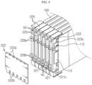
- FIG. 3 is a partial perspective view schematically showing isolated components with respect to a battery module, according to an embodiment of the present disclosure.
- FIG. 4 is a partial perspective view schematically showing isolated components with respect to a battery module, according to an embodiment of the present disclosure.
- FIG. 5 is a side view schematically showing isolated components of a bus bar assembly with respect to a battery module, according to an embodiment of the present disclosure.
- the bus bar assembly 220 includes a plurality of connection bus bars 221, a plurality of sensing bus bars 223, and a plurality of bus bar frames 225.
- the bus bar assembly 220 may be positioned at a front side or rear side of the cell stack 210 such as to be electrically connected to any one of the positive electrode lead 111 and the negative electrode lead 112 of the plurality of battery cells 100 of the cell stack 210.
- the battery module 200 may include a bus bar assembly (not shown) having a configuration different from the bus bar assembly 220.
- a bus bar assembly having a different configuration may be provided at the rear side of the cell stack 210.
- the bus bar assembly having the different configuration may include a plurality of bus bars (not shown) for electric connection of the positive electrode lead 111 of the cell stack 210.
- the bus bar assembly having the different configuration may not include the sensing bus bar 223 unlike the bus bar assembly 220.
- connection bus bar 221 may be configured to be electrically connected to any one of the positive electrode lead 111 and the negative electrode lead 112 provided in each of the plurality of battery cells 100.
- the connection bus bar 221 may include at least one electric conductive material.
- the electric conductive material may be a metal having high conductivity, such as copper, aluminum, nickel, gold, or an alloy thereof.
- one side surface 221c of the connection bus bar 221 may be configured to contact another side surface of any one of the positive electrode lead 111 and the negative electrode lead 112 provided in the battery cell 100.
- any one of the positive electrode lead 111 and the negative electrode lead 112 may contact the one side surface 221c of the connection bus bar 221 via a method such as laser welding or the like.
- the battery module 200 of the present disclosure may include the six connection bus bars 221 mounted respectively on the six bus bar frames 225 and the six battery cells 100 electrically respectively connected to the six connection bus bars 221.
- the other side surface of the negative electrode lead 112 of each of the six battery cells 100 may contact or be combined to the one side surface of each of the six connection bus bars 221.
- the electrode lead does not need to be bent for electric connection with a bus bar, a bending process may be omitted, and since there is no spring back phenomenon caused by bending of the electrode lead, the electrode lead and the bus bar easily maintains a contact state, and thus deterioration of weldability may be prevented.
- the sensing bus bar 223 is provided to be electrically connected to the sensing negative electrode lead or the sensing positive electrode lead 113 provided in each of the plurality of battery cells 100.
- the sensing bus bar 223 may include at least one electric conductive material.
- the electric conductive material may be a metal having high conductivity, such as copper, aluminum, nickel, gold, or an alloy thereof.
- one side surface 223c of the sensing bus bar 223 may be configured to contact the other side surface of any one of the sensing positive electrode lead 113 or the sensing negative electrode lead provided in the battery cell 100.
- any one of the sensing positive electrode lead 113 and the sensing negative electrode lead may contact the one side surface 223c of the sensing bus bar 223 via a method such as laser welding or the like.
- the battery module 200 of the present disclosure may include the six sensing bus bars 223 contacting the six sensing positive electrode leads 113 of the six battery cells 100.
- the other side surface of the sensing positive electrode lead 113 of each of the six battery cells 100 may contact or be combined to the one side surface 223c of each of the six sensing bus bars 223.
- the sensing positive electrode lead 113 does not need to be bent for electric connection with a bus bar, a bending process may be omitted, and since there is no spring back phenomenon caused by bending of the sensing positive electrode lead 113, the sensing positive electrode lead 113 and the bus bar easily maintains a contact state, and thus deterioration of weldability may be prevented.
- the bus bar frame 225 may include a connection accommodating portion 227 in which the connection bus bar 221 is accommodated.
- the connection accommodating portion 227 may have an accommodating space such that the connection bus bar 221 is accommodated and mounted on one side of the bus bar frame 225 in a left-and-right direction.
- the connection accommodating portion 227 may include a partition wall 228 such that contact between the connection bus bar 221 and the sensing bus bar 223 is insulated.
- the bus bar frame 225 may include an electric insulating material.
- the electric insulating material may be polyvinyl chloride plastic.
- connection accommodating portion 227 in which the connection bus bar 221 is accommodated may be formed at one side portion of one bus bar frame 225 in the left-and-right direction.
- the partition wall 228 may be formed at an upper portion of the connection accommodating portion 227.
- the bus bar frame 225 includes a sensing accommodating portion 229 where the sensing bus bar 223 is accommodated.
- the sensing accommodating portion 229 has an accommodating space such that the sensing bus bar 223 is accommodated and mounted on the bus bar frame 225.
- the sensing accommodating portion 229 may include the partition wall 228 for insulation with the connection bus bar 221.
- the sensing accommodating portion 229 where the sensing bus bar 223 is accommodated may be formed at a side surface of one bus bar frame 225 in the left-and-right direction.
- the partition wall 228 may be formed at a lower portion of the sensing accommodating portion 229 to prevent contact between the sensing bus bar 223 and the connection bus bar 221.
- connection accommodating portion 227 and the sensing accommodating portion 229 may be provided at a right side of the bus bar frame 225.
- the connection accommodating portion 227 may be formed at a lower portion of the sensing accommodating portion 229.
- the connection accommodating portion 227 may have a structure recessed in a left direction such that the connection bus bar 221 is accommodated and inserted therein.
- a recessed depth of the connection accommodating portion 227 may be equal to or greater than a thickness of the connection bus bar 221 in the left-and-right direction.
- the sensing accommodating portion 229 may be formed at the left side of the bus bar frame 225. Moreover, the sensing accommodating portion 229 may be formed at an upper portion of the connection accommodating portion 227. Also, the sensing accommodating portion 229 may have a structure recessed such that the sensing bus bar 223 is accommodated and inserted therein. Moreover, a recessed depth of the sensing accommodating portion 229 may be equal to or greater than a thickness of the sensing bus bar 223 in the left-and-right direction.
- connection accommodating portion 227 and the sensing accommodating portion 229 at the right side of the bus bar frame 225, the connection bus bar 221 and the sensing bus bar 223 contact and be connected to the electrode lead and the sensing electrode lead 113 by simply accommodating the bus bar frame 225 in the terrace portion S of the battery cell 100, and thus space utility of the battery module 200 may be increased and manufacturing processes may be simplified.
- connection accommodating portion 227 and the sensing accommodating portion 229 by forming the partition wall 228 defining the connection accommodating portion 227 and the sensing accommodating portion 229, short circuit between the connection bus bar 221 and the sensing bus bar 223 may be effectively prevented.
- connection bus bar 221 may be connected to the positive electrode lead 111 or the negative electrode lead 112.
- sensing bus bar 223 may be connected to any one of the sensing negative electrode lead and the sensing positive electrode lead 113 having an opposite polarity from the electrode lead to which the connection bus bar 221 is connected.
- one side surface (right side surface) of the bus bar frame 225 may contact the negative electrode lead 112 of the battery cell 100 and one side surface (right side surface) of the sensing bus bar 223 may contact the sensing positive electrode lead 113 of the battery cell 100.
- the plurality of bus bar frames 225 may be stacked on each other in a stack direction (left-and-right direction) of the plurality of battery cells 100.
- the bus bar frame 225 may separately include a coupling member (not shown) such that the plurality of bus bar frames 225 are coupled and fixed to each other.
- the coupling member may include a coupling bolt penetrating the plurality of bus bar frames 225.
- bus bar frame 225 may have a coupling structure (not shown) such that the plurality of bus bar frames 225 are coupled and fixed to each other.
- the coupling structure may include an insertion protrusion protruding in a left direction at the left side surface of the bus bar frame 225 and an accommodating groove where the insertion protrusion is accommodated at the right side surface of the bus bar frame 225.
- the coupling structure may be a female-male coupling structure.
- the bus bar assembly 220 may include a connection plate 222 configured such that the plurality of connection bus bars 221 are electrically connected to each other.
- the connection plate 222 may be combined and fixed to a front surface of the plurality of connection bus bars 221.
- the connection plate 222 may be combined to a front surface portion of each of the plurality of connection bus bars 221.
- a plurality of insertion groove 222a recessed in a downward direction may be formed at the top of the connection plate 222 at regular intervals.
- the insertion groove 222a may have an uneven shape of a quadrangular structure.
- a combining protrusion 228a that is inserted into the insertion groove 222a formed at the top of the connection plate 222 may be formed on a front surface of the bus bar frame 225.
- the combining protrusion 228a may have a rectangular parallelepiped shape such as to be inserted into the insertion groove 222a of the quadrangular structure.
- the combining protrusion 228a may protrude in a downward direction.
- a plurality of insertion grooves 222b recessed in an upward direction may be formed at the bottom of the connection plate 222 at regular intervals.
- the insertion groove 222b may have an uneven shape of a quadrangular structure.
- a combining protrusion 228b that is inserted into the insertion groove 222b formed at the bottom of the connection plate 222 may be formed on the front surface of the bus bar frame 225.
- the combining protrusion 228b may have a rectangular parallelepiped shape such as to be inserted into the insertion groove 222b of the quadrangular structure.
- connection plate 222 may be formed to contact the front surface of the plurality of connection bus bars 221.
- the six insertion grooves 222a recessed in a center direction may be formed at the top of the connection plate 222 and the six insertion grooves 222b recessed in the center direction may be formed at the bottom.
- the six combining protrusions 228a that are insertable into the insertion groove 222a formed at the top of the connection plate 222 may be formed at the top of the connection bus bar 221.
- the six combining protrusions 228b that are insertable into the insertion groove 222b formed at the bottom of the connection plate 222 may be formed at the bottom of the connection bus bar 221.
- connection plate 222 may electrically connect the plurality of connection bus bars 221 by simply being mounted on the front surface of the bus bar frame 225, and thus manufacturing processes are simplified, thereby increasing manufacture efficiency.
- a combining structure of the insertion groove 222a formed at the connection plate 222 and the combining protrusion 228b formed at the bus bar frame 225 enables the connection plate 222 to be stably mounted on the front surface of the bus bar frame 225, and thus a welding job between the connection plate 222 and the plurality of connection bus bars 221 may be facilitated.
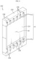
- FIG. 6 is a perspective view schematically illustrating isolated components of a sensing assembly with respect to a battery module, according to an embodiment of the present disclosure.
- the sensing assembly 230 includes a circuit board 231 and a sensing frame 233.
- the circuit board 231 may be a board on which a circuit for transmitting a sensed current, voltage, temperature, or the like of the battery cell 100 to a battery management system (BMS) via a signal is printed. Accordingly, the circuit board 231 may transmit the sensed voltage of the battery cell 100 to an external component, such as the BMS, via a printed circuit and output pin.
- the circuit board 231 may include an internal circuit configured to protect the plurality of battery cells 100 from over-discharging, over-charging, over-heating, or the like.
- the circuit board 231 may be embodied as a printed circuit board on which an internal circuit pattern is printed.
- the sensing frame 233 is mounted on the front surface of the bus bar assembly 220 positioned at a front side of the cell stack 210.
- the sensing frame 233 may be positioned to face the front surface of the connection bus bar 221 and sensing bus bar 223 mounted on the bus bar frame 225.
- the sensing frame 233 may be mounted on a rear surface of the bus bar assembly 220 positioned at the rear side of the cell stack 210. Moreover, the sensing frame 233 may be positioned to face the rear surface of the connection bus bar 221 and sensing bus bar 223 mounted on the bus bar frame 225.
- the sensing frame 233 may include an electric insulating material.
- the electric insulating material may be polyvinyl chloride plastic.
- the sensing frame 233 is positioned at the front surface of the bus bar assembly 220, an electric connection section of the connection bus bar 221 and the sensing bus bar 223 of the bus bar assembly 220 is reduced, thereby reducing the number or size of members for electric connection, and thus manufacturing costs may be reduced and the more compact battery module 200 may be manufactured.
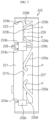
- FIG. 7 is a partial cross-sectional view schematically showing a cross section of a battery module taken along a line A-A' of FIG. 1 .
- the sensing frame 233 includes a board embedding portion 234 accommodating the circuit board 231 therein.
- the board embedding portion 234 may have an internal space in the sensing frame 233 such that at least a portion of the circuit board 231 is inserted therein.
- an insert injection method may be used as a method for inserting the circuit board 231 into the sensing frame 233.
- a method of manufacturing the sensing frame 233 into which the circuit board 231 is inserted may include: (a) mounting and fixing the prepared circuit board 231 inside a mold; and (b) injecting a melted insulating material into the mold to combine with at least a portion of the circuit board 231 and forming an outer shape of the sensing frame 233 by solidifying the melted material.
- the circuit board 231 by inserting the circuit board 231 into the sensing frame 233, not only the circuit board 231 is stably fixed to the sensing frame 233 without having to use a separate adhesive member, but also the volume occupied by the circuit board 231 in a front-and-back direction is largely reduced, and thus ultimately, the size of the sensing assembly 230 may be reduced.
- an exposed portion H3 may be formed at the sensing frame 233 such that a portion of the circuit board 231 is exposed.
- an outer peripheral portion of the circuit board 231 may be inserted into the sensing frame 233, and the sensing frame 233 may have the exposed portion H3 in an opened shape such that a center portion of the circuit board 231 is externally exposed.
- a job of replacing or recovering components or newly mounting a component in an exposed region of the circuit board 231 may be facilitated through the exposed portion H3.
- the sensing frame 233 may include an insertion groove H1 configured such that at least a portion of each of the connection bus bar 221 and sensing bus bar 223 is inserted.
- the insertion grooves H1 recessed forward may be formed at the rear surface of the sensing frame 233 at regular intervals.
- a plurality of insertion grooves H1a arranged in the left-and-right direction may be formed at the top of the rear surface of the sensing frame 233.
- the insertion groove H1a formed at the top of the sensing frame 233 may be configured such that a portion of the sensing bus bar 223 of the bus bar assembly 220 is inserted.
- a portion of the top portion of the sensing bus bar 223 may be inserted into the insertion groove H1a.
- a plurality of insertion grooves H1b arranged in the left-and-right direction may be formed at the bottom of the rear surface of the sensing frame 233.
- the insertion groove H1b formed at the bottom of the sensing frame 233 may be configured such that a portion of the connection bus bar 221 of the bus bar assembly 220 is inserted.
- a portion of the bottom portion of the connection bus bar 221 may be inserted into the insertion groove H1b.
- the sensing assembly 230 may further include a sensing terminal 236 for achieving electric connection of the circuit board 231 to the connection bus bar 221 and the sensing bus bar 223.
- the sensing terminal 236 may be inserted into the insertion groove H1b of the sensing frame 233.
- the sensing terminal 236 may be configured to contact one portion of the connection bus bar 221 inserted into the insertion groove H1b of the sensing frame 233 by being inserted into the insertion groove H1b.
- the sensing terminal 236 may have one end electrically connected to the circuit board 231 and the other end electrically connected to the connection bus bar 221. In other words, when the sensing terminal 236 is inserted into the insertion groove H1b formed at the bottom of the sensing frame 233, the other end of the sensing terminal 236 may contact and be connected to the connection bus bar 221.
- the sensing terminal 236 may be inserted into the insertion groove H1a formed at the top of the rear surface of the sensing frame 233.
- the sensing terminal 236 may be configured to contact one portion of the sensing bus bar 223 inserted into the insertion groove H1a of the sensing frame 233 by being inserted into the insertion groove H1a.
- the sensing terminal 236 may have one end electrically connected to the circuit board 231 and the other end electrically connected to the sensing bus bar 223.
- the sensing terminal 236 when the sensing terminal 236 is inserted into the insertion groove H1a formed at the top of the sensing frame 233, the other end of the sensing terminal 236 may contact and be connected to the sensing bus bar 223.
- the sensing terminal 236 may include a plate shape elongated in an inward direction from the circuit board 231.
- the sensing terminal 236 may have a plate shape erected in the top-and-bottom direction and having a wide side surface in the left-and-right direction such as to surface-contact one side surface of the connection bus bar 221 or sensing bus bar 223 in the left-and-right direction.
- a curved portion 236e modified to have elasticity may be formed at an end portion of the sensing terminal 236 in an elongated direction.
- the curved portion 236e of the sensing terminal 236 may be elastically modified by being adhered to the connection bus bar 221 or sensing bus bar 223 inserted into the insertion grove H1 of the sensing frame 233.
- the sensing terminal 236 inserted into the insertion groove H1b may also have the same shape as the sensing terminal 236 described above with reference to FIG. 7 .
- the curved portion 236e of the sensing terminal 236 is elastically adhered to the connection bus bar 221 or sensing bus bar 223, electric connection reliability of the sensing terminal 236 to the connection bus bar 221 or sensing bus bar 223 may be increased.
- the sensing frame 233 may include a connection protruding portion 238 protruding inward to support the sensing terminal 236 in a horizontal direction.
- the connection protruding portion 238 may extend from an inner wall of the insertion groove H1 where the sensing terminal 236 is inserted.
- connection protruding portion 238 may be formed such that an inner side surface thereof is connected to an inner surface of the insertion groove H1. Accordingly, one end of the sensing terminal 236 is connected to the circuit board 231 and protrudes backward from the insertion groove H1 while the other end extending backward of the sensing terminal 236 may be supported by the connection protruding portion 238 in the horizontal direction (the left-and-right direction).
- the sensing terminal 236 is inserted into the insertion groove H1 of the sensing frame 233, one end portion of the sensing terminal 236 is connected to the circuit board 231, and the other end portion of the sensing terminal 236 is extended to the one side surface (left side surface) of the connection protruding portion 238.
- the curved portion 236e is elastically modified by the sensing bus bar 223 while the sensing bus bar 223 is inserted into the insertion groove H1, and thus the sensing terminal 236 may be adhered to one side surface (right side surface) of the sensing bus bar 223.
- the curved portion 236e may be elastically modified by the connection bus bar 221 while the connection bus bar 221 is inserted into the insertion grove H1, and thus the sensing terminal 236 may be adhered to one side surface (right side surface) of the connection bus bar 221.
- An insertion portion H2 may be formed on the bus bar frame 225 such that the connection protruding portion 238 is inserted backward.
- the sensing terminal 236 may be disposed between the connection bus bar 221 and the connection protruding portion 238 or between the sensing bus bar 223 and the connection protruding portion 238.
- the insertion portion H2 may be formed on the other side surface (left side surface) that is opposite to the one side surface where the connection accommodating portion 227 is formed. Also, the insertion portion H2 may be formed on the other side surface (left side surface) that is opposite to the one side surface where the sensing accommodating portion 229 is formed. Also, the insertion portion H2 may be formed on each of the top and bottom of the front surface of the bus bar frame 225.
- the insertion portion H2 may be formed on each of the top and bottom of the front surface of the bus bar frame 225, which is a position corresponding to the connection protruding portion 238 formed in the sensing frame 233.
- the insertion portion H2 formed in one bus bar frame 225 may face the connection accommodating portion 227 or the sensing accommodating portion 229 of the other adjacent bus bar frame 225.
- the connection protruding portion 238 facing the side surface of the connection bus bar 221 or sensing bus bar 223 of one bus bar frame 225 may be inserted into the insertion portion H2 formed in the other adjacent bus bar frame 225.
- the six insertion portions H2 may be formed on each of the top and bottom of the front surface of the bus bar frame 225.
- connection bus bar 221 and sensing bus bar 223 formed in the bus bar assembly 220 by simply inserting one portion of the connection bus bar 221 and sensing bus bar 223 formed in the bus bar assembly 220 into the insertion groove H1 formed in the sensing frame 233 and inserting the connection protruding portion 238 formed in the sensing frame 233 into the insertion portion H2 of the bus bar frame 225, not only the sensing assembly 230 is mounted on the front surface of the bus bar assembly 220, but also electric connection of the circuit board 231 to the connection bus bar 221 and sensing bus bar 223 may be easily achieved.
- connection accommodating portion 227 may include a connection pressurizing portion 226A pressurizing a rear side 221b of the connection bus bar 221.
- connection pressurizing portion 226A may have a structure pressurizing the connection bus bar 221 such that a front end portion of the connection bus bar 221 protrudes outside the connection accommodating portion 227.
- connection pressurizing portion 226A may include a support 226a elongated in one direction.
- the support 226a may be elongated forward to have an inclination from a corner of a rear side of the connection accommodating portion 227.
- the support 226a may be elongated towards the center of the connection bus bar 221 from each of both corners of the rear side of the connection accommodating portion 227.
- An end portion of the support 226a in an elongated direction may elastically pressurize the rear side 221b of the connection bus bar 221.
- the end portion of the support 226a in the elongated direction may have a structure P curved roundly backward.
- the structure P curved roundly backward pressurizes the rear side 221b of the connection bus bar 221 with a smooth curved surface formed in a round curve, the support 226a smoothly pressurizes the connection bus bar 221 without damaging the connection bus bar 221.
- the sensing accommodating portion 229 may include a sensing pressurizing portion 226B pressurizing a rear side 223b of the sensing bus bar 223.
- the sensing pressuring portion 226B may have a structure pressurizing the sensing bus bar 223 such that a front end portion of the sensing bus bar 223 protrudes outside the sensing accommodating portion 229.
- the sensing pressurizing portion 226B may include a support 226b elongated in one direction.
- the support 226b may be elongated forward to have an inclination from a corner of a rear side of the sensing accommodating portion 229.
- the support 226b may be elongated towards a center portion of the sensing bus bar 223 in the up-and-down direction from each of both corners of the rear side of the sensing accommodating portion 229.
- an end portion of the support 226 in an elongated direction may elastically pressurize the rear side 223b of the sensing bus bar 223. Also, the end portion of the support 226b in the elongated direction may have the structure P curved roundly backward.
- the structure P curved roundly backward pressurizes the rear side 223b of the sensing bus bar 223 with a smooth curved surface formed in a round curve
- the support 226b smoothly pressurizes the sensing bus bar 223 without damaging the sensing bus bar 223.
- connection pressurizing portion 226A formed in the connection accommodating portion 227 and the sensing pressurizing portion 226B formed in the sensing accommodating portion 229 elastically absorb an impact occurred when the connection bus bar 221 and the sensing bus bar 223 are inserted into the insertion groove H1 of the sensing frame 233 of FIG. 6 , damage to the sensing frame 233, the sensing terminal 236, the circuit board 231, or the like caused by bus bar insertion may be effectively prevented.
- a stopper 224a blocking both end portions of the connection bus bar 221 in the up-and-down direction from moving forward may be formed in the connection accommodating portion 227.
- the connection pressurizing portion 226A may pressurize the rear side of the connection bus bar 221 while the stopper 224a blocking the connection bus bar 221 from protruding externally above a certain portion may be formed such that a front end portion of the connection bus bar 221 protrudes outside of the connection accommodating portion 227 at the connection accommodating portion 227.
- the two supports 226b pressurizing the rear side of the connection bus bar 221 are formed at the connection accommodating portion 227 formed in the bus bar frame 225 and the two stoppers 224a are formed to block the both end portions of the connection bus bar 221 in the up-and-down direction from moving forward.
- connection bus bar 221 pressurizes and is inserted into the connection accommodating portion 227 while temporarily pushing the connection pressurizing portion 226A backward, and when the pressurization and insertion are completed, the connection pressurizing portion 226A pressurizes the rear side of the connection bus bar 221 in an outward direction, thereby positioning a front end of the connection bus bar 221 to protrude outside the connection accommodating portion 227 by a predetermined distance.
- connection pressuring portion 226A and the stopper 224a formed in the connection accommodating portion 227 not only facilitate a work of installing the connection bus bar 221 to the connection accommodating portion 227, but also position the front end portion of the connection bus bar 221 to protrude outside the connection accommodating portion 227 such that the connection bus bar 221 is suitably inserted into the insertion groove H1 of the sensing frame 233.
- the present disclosure not only increases efficiency of an assembling process of the battery module 200 and reduces component damage occurred during the assembling process, but also increases reliability of electric connection between the bus bar assembly 220 and the sensing assembly 230.
- a stopper 224b blocking both end portions of the sensing bus bar 223 in the up-and-down direction from moving forward may be formed in the sensing accommodating portion 229.
- the sensing pressurizing portion 226B pressurizes the rear side 223b of the sensing bus bar 223 while the stopper 224b blocking the sensing bus bar 223 from protruding externally above a certain region may be formed such that a front end portion of the sensing bus bar 223 protrudes outside of the sensing accommodating portion 229 at the sensing accommodating portion 229.
- the two supports 226b pressurizing the rear side 223b of the sensing bus bar 223 are formed at the sensing accommodating portion 229 formed in the bus bar frame 225 and the two stoppers 224b are formed to block the both end portions of the sensing bus bar 223 in the up-and-down direction from moving forward.
- the sensing bus bar 223 pressurizes and is inserted into the sensing accommodating portion 229 while temporarily pushing the sensing pressurizing portion 226B backward, and when the pressurization and insertion are completed, the sensing pressurizing portion 226B pressurizes the rear side 223b of the sensing bus bar 223, thereby positioning a front end of the sensing bus bar 223 to protrude outside the sensing accommodating portion 229 by a predetermined distance.
- the sensing pressuring portion 226B and the stopper 224b formed in the sensing accommodating portion 229 not only facilitate a work of installing the sensing bus bar 223 to the sensing accommodating portion 229, but also position the front end portion of the sensing bus bar 223 to protrude outside the sensing accommodating portion 229 such that the sensing bus bar 223 is suitably inserted into the insertion groove H1 of the sensing frame 233.
- the present disclosure not only increases efficiency of an assembling process of the battery module 200 and reduces component damage occurred during the assembling process, but also increases reliability of electric connection between the bus bar assembly 220 and the sensing assembly 230.
- a bump 228c may be formed in the connection accommodating portion 227 to prevent the connection bus bar 221 from being displaced in the horizontal direction.
- the bump 228c may extend from the partition wall 228 defining the connection accommodating portion 227 and the sensing accommodating portion 229 to face the connection bus bar 221.
- the bump 228c may be formed in the sensing accommodating portion 229 to prevent the sensing bus bar 223 from being displaced in the horizontal direction.
- the bump 228c may extend from the partition wall 228 defining the connection accommodating portion 227 and the sensing accommodating portion 229 to face the sensing bus bar 223.
- the bump 228c may be additionally formed at a bottom end portion of the bus bar frame 225 to face the bottom of the connection bus bar 221.
- the two bumps 228c may be formed in the bus bar frame 225 to prevent the both end portions of the connection bus bar 221 in the up-and-down direction mounted in the connection accommodating portion 227 from being displaced in the horizontal direction.
- the bump 228c formed at the partition wall 228 defining the connection accommodating portion 227 and the sensing accommodating portion 229 may face the bottom of the sensing bus bar 223 and the top of the connection bus bar 221, thereby preventing the sensing bus bar 223 and the connection bus bar 221 from being displaced in the horizontal direction.
- the remaining bump 228c formed at the bottom of the bus bar frame 225 faces the bottom of the connection bus bar 221, thereby effectively preventing displacement of the connection bus bar 221.
- a battery pack (not shown) according to an embodiment of the present disclosure includes at least one battery module 200.
- the battery pack may include a configuration (a pack bus bar) accommodating at least one battery module in a pack case and electrically connecting the at least one battery module.
- the battery pack may include a BMS or the like to detect a voltage or current of the battery module and control a battery.
- the present disclosure provides a vehicle including the battery pack.
- the vehicle may include an accommodating portion (not shown) accommodating the battery pack therein.
- connection pressurizing portion 210 cell stack 226B: sensing pressurizing portion 100: battery cell 226a, 226b: support 111: positive electrode lead 224a, 224b: stopper 112: negative electrode lead 228c: bump 113: sensing electrode lead 230: sensing assembly 220: bus bar assembly 233: sensing frame 221: connection bus bar 234: board embedding portion 223: sensing bus bar H1: insertion groove 222: connection plate 236: sensing terminal 225: bus bar frame 236e: curved portion 227: connection accommodation portion 238: connection protruding portion
- the present disclosure relates to a battery module including a bus bar assembly and a sensing bar assembly. Also, the present disclosure is applicable to industries related to a battery pack including a plurality of battery modules and an electric part, an electronic device including the battery pack, an energy storage system, or a vehicle.
Landscapes
- Chemical & Material Sciences (AREA)
- Chemical Kinetics & Catalysis (AREA)
- Electrochemistry (AREA)
- General Chemical & Material Sciences (AREA)
- Engineering & Computer Science (AREA)
- Manufacturing & Machinery (AREA)
- Microelectronics & Electronic Packaging (AREA)
- Materials Engineering (AREA)
- Aviation & Aerospace Engineering (AREA)
- Connection Of Batteries Or Terminals (AREA)
- Battery Mounting, Suspending (AREA)
- Secondary Cells (AREA)
Claims (14)
- Batteriemodul (200) umfassend:einen Zellenstapel (210), der als eine Vielzahl von beutelartigen Batteriezellen (100) gebildet ist, die in einer Stapelrichtung aufeinander gestapelt sind, wobei die Batteriezellen (100) mindestens eine abtastende negative Elektrodenleitung und eine abtastende positive Elektrodenleitung (113) zusätzlich zu einer positiven Elektrodenleitung (111) und einer negativen Elektrode (112) umfassen;wobei die positive Elektrodenleitung (111) an einem Endabschnitt basierend auf einer Mitte einer aus der Vielzahl von Batteriezellen (100) vorgesehen ist und die negative Elektrodenleitung (112) an dem anderen Endabschnitt basierend auf der Mitte der einen aus der Vielzahl von Batteriezellen (100) vorgesehen ist, unddie abtastende negative Elektrodenleitung an dem einen Endabschnitt mit einem vorbestimmten Abstand von der positiven Elektrodenleitung (111) vorgesehen ist und/oder die abtastende positive Elektrodenleitung (113) an dem anderen Endabschnitt mit einem vorbestimmten Abstand von der negativen Elektrodenleitung (112) vorgesehen ist,eine Sammelschienenanordnung (220), umfassend eine Vielzahl von Verbindungssammelschienen (221), die elektrisch mit einer der positiven Elektrodenleitung (111) und der negativen Elektrodenleitung (112) verbunden sind, die in jeder der Vielzahl von Batteriezellen (100) enthalten sind, eine Vielzahl von Abtastsammelschienen (223), die elektrisch mit der abtastenden negativen Elektrodenleitung oder der abtastenden positiven Elektrodenleitung (113) verbunden sind, die in jeder der Vielzahl von Batteriezellen (100) enthalten sind, und eine Vielzahl von Sammelschienenrahmen (225), die jeweils einen Verbindungsaufnahmeabschnitt (227) umfassen, in dem eine jeweilige der Vielzahl von Verbindungssammelschienen (221) aufgenommen ist, und einen Abtastaufnahmeabschnitt (229), in dem eine jeweilige der Vielzahl von Abtastsammelschienen (223) aufgenommen ist; undeine Fühleranordnung (230), die eine Leiterplatte (231) umfasst, die elektrisch mit der Vielzahl von Verbindungssammelschienen (221) und der Vielzahl von Abtastsammelschienen (223) verbunden ist, und einen Abtastrahmen (223), der auf einer vorderen Oberfläche der Sammelschienenanordnung (220) montiert ist, bei der es sich um eine Oberfläche handelt, die von dem Zellenstapel (210) abgewandt ist, und wo ein Platteneinbettungsabschnitt (234) gebildet ist, der die Leiterplatte (231) darin aufnimmt.
- Batteriemodul (200) nach Anspruch 1, wobei der Verbindungsaufnahmeabschnitt (227) und der Abtastaufnahmeabschnitt (229) an einer Seitenfläche eines aus der Vielzahl von Sammelschienenrahmen (225) gebildet sind,der Verbindungsaufnahmeabschnitt (227) eine vertiefte Struktur hat, so dass eine aus der Vielzahl von Verbindungssammelschienen (221) darin aufgenommen und eingefügt wird und der Abtastaufnahmeabschnitt (229) eine vertiefte Struktur aufweist, so dass eine der Vielzahl von Abtastsammelschienen (223) darin aufgenommen und eingefügt wird, undeine Trennwand (228) zwischen dem Verbindungsaufnahmeabschnitt (227) und dem Abtastaufnahmeabschnitt (229) vorgesehen ist, um den Verbindungsaufnahmeabschnitt (227) und den Abtastaufnahmeabschnitt (229) zu trennen.
- Batteriemodul (200) nach Anspruch 2, wobei mindestens ein Teil einer Seitenfläche des Sammelschienenrahmens (225) auf einem Terrassenabschnitt (S) der Batteriezelle (100) aufgenommen ist.
- Batteriemodul (200) nach Anspruch 3, wobei die Vielzahl von Sammelschienenrahmen (225) so angeordnet sind, dass sie in einer Stapelrichtung der Vielzahl von Batteriezellen (100) aufeinander gestapelt werden, und
eine Verbindungsplatte (222), die konfiguriert ist, um die Vielzahl von Verbindungssammelschienen (221) elektrisch miteinander zu verbinden, kombiniert und an einer vorderen Oberfläche der Vielzahl von Verbindungssammelschienen (221) befestigt ist, die eine von dem Zellenstapel (210) abgewandte Oberfläche ist. - Batteriemodul (200) nach Anspruch 1, wobei der Abtastrahmen (233) eine Einführungsnut (222a) umfasst, die konfiguriert ist, so dass zumindest ein Teil der Verbindungssammelschienen (221) und der Abtastsammelschienen (223) darin eingefügt ist.
- Batteriemodul (200) nach Anspruch 5, wobei die Fühleranordnung (230) weiterhin eine Abtastanschluss (236) umfasst, die in der Einführungsnut (222a) positioniert ist und deren eines Ende elektrisch mit der Leiterplatte (231) und deren anderes Ende elektrisch mit der Verbindungssammelschiene (221) oder der Abtastsammelschiene (223) verbunden ist.
- Batteriemodul (200) nach Anspruch 6, wobei der Abtastanschluss (236) eine Plattenform hat, die sich von der Leiterplatte (231) in einer Richtung nach innen erstreckt, und
ein gekrümmter Abschnitt (236e), der so modifiziert ist, dass er elastisch ist, an einem Endabschnitt des Abtastanschlusses (236) in einer länglichen Richtung gebildet ist. - Batteriemodul (200) nach Anspruch 6, wobei der Abtastrahmen (233) einen vorstehenden Verbindungsabschnitt (238) umfasst, der nach innen vorsteht, um den Abtastanschluss (236) in einer horizontalen Richtung zu halten, und
jeder der Vielzahl von Sammelschienenrahmen (225) einen Einschubabschnitt (H2) umfasst, so dass der vorstehende Verbindungsabschnitt (238) nach hinten eingeführt wird. - Batteriemodul (200) nach Anspruch 1, wobei der Verbindungsaufnahmeabschnitt (227) einen Verbindungsdruckbeaufschlagungsabschnitt (226A) umfasst, der eine Rückseite (221b) jeder der Vielzahl von Verbindungssammelschienen (221) mit Druck beaufschlagt, die eine dem Zellenstapel (210) zugewandte Seite ist, so dass ein vorderer Endabschnitt jeder der Vielzahl von Verbindungssammelschienen (221), der ein von dem Zellenstapel (210) abgewandter Endabschnitt ist, aus dem Verbindungsaufnahmeabschnitt (227) herausragt, und
der Abtastaufnahmeabschnitt (229) einen Abtastdruckbeaufschlagungsabschnitt (226B) umfasst, der eine Rückseite (223b) jeder der Vielzahl von Abtastsammelschienen (223) unter Druck setzt, die eine dem Zellenstapel (210) zugewandte Seite ist, so dass ein vorderer Endabschnitt jeder der Vielzahl von Abtastsammelschienen (223), der ein vom Zellenstapel (210) abgewandter Endabschnitt ist, aus dem Abtastaufnahmeabschnitt (229) herausragt. - Batteriemodul (200) nach Anspruch 9, wobei der Verbindungsdruckbeaufschlagungsabschnitt (226A) einen Träger (226a) umfasst, der so langgestreckt ist, dass er eine Neigung von einer Ecke des Verbindungsaufnahmeabschnitts (227) aufweist, wobei ein Endabschnitt des Trägers (226a) in einer Längsrichtung die Rückseite (221b) jeder der Vielzahl von Verbindungssammelschienen (221) elastisch unter Druck setzt, und
der Abtastdruckbeaufschlagungsabschnitt (226B) einen Träger (226b) umfasst, der so langgestreckt ist, dass er eine Neigung von einer Ecke des Abtastaufnahmeabschnitts (229) aufweist, wobei ein Endabschnitt des Trägers (226b) in einer Längsrichtung die Rückseite (223b) jeder der Vielzahl von Abtastsammelschienen (223) elastisch unter Druck setzt. - Batteriemodul (200) nach Anspruch 9, wobei ein Stopper (224a), der beide Endabschnitte jeder der Vielzahl von Verbindungssammelschienen (221) in einer Auf- und Abwärtsrichtung, die eine Richtung senkrecht zu der Stapelrichtung der Vielzahl von Batteriezellen (100) ist, daran hindert, sich in einer Richtung weg von dem Zellenstapel (210) vorwärts zu bewegen, an dem Verbindungsaufnahmeabschnitt (227) gebildet ist, und
ein Stopper (224b), der beide Endabschnitte jeder der Vielzahl von Abtastsammelschienen (223) in der Auf- und Abwärtsrichtung daran hindert, sich in der Richtung weg von dem Zellenstapel (210) vorwärts zu bewegen, an dem Abtastaufnahmeabschnitt (229) gebildet ist. - Batteriemodul (200) nach Anspruch 9, wobei ein Höcker (228c), der verhindert, dass jede der Vielzahl von Verbindungssammelschienen (221) in einer horizontalen Richtung verschoben wird, an dem Verbindungsaufnahmeabschnitt (227) gebildet ist, und
ein Höcker (228c), der verhindert, dass jede der Vielzahl von Abtastsammelschienen (223) in der horizontalen Richtung verschoben wird, an dem Abtastaufnahmeabschnitt (229) gebildet ist. - Batteriepack, umfassend mindestens ein Batteriemodul (200) nach einem der Ansprüche 1 bis 12.
- Fahrzeug umfassend den Batteriepack nach Anspruch 13.
Priority Applications (1)
| Application Number | Priority Date | Filing Date | Title |
|---|---|---|---|
| EP24173037.3A EP4386954A3 (de) | 2017-11-16 | 2018-11-06 | Batteriemodul mit sensoranordnung und sammelschienenanordnung |
Applications Claiming Priority (2)
| Application Number | Priority Date | Filing Date | Title |
|---|---|---|---|
| KR1020170152984A KR102198848B1 (ko) | 2017-11-16 | 2017-11-16 | 센싱 어셈블리 및 버스바 어셈블리를 포함하는 배터리 모듈 |
| PCT/KR2018/013395 WO2019098588A1 (ko) | 2017-11-16 | 2018-11-06 | 센싱 어셈블리 및 버스바 어셈블리를 포함하는 배터리 모듈 |
Related Child Applications (2)
| Application Number | Title | Priority Date | Filing Date |
|---|---|---|---|
| EP24173037.3A Division-Into EP4386954A3 (de) | 2017-11-16 | 2018-11-06 | Batteriemodul mit sensoranordnung und sammelschienenanordnung |
| EP24173037.3A Division EP4386954A3 (de) | 2017-11-16 | 2018-11-06 | Batteriemodul mit sensoranordnung und sammelschienenanordnung |
Publications (3)
| Publication Number | Publication Date |
|---|---|
| EP3671937A1 EP3671937A1 (de) | 2020-06-24 |
| EP3671937A4 EP3671937A4 (de) | 2020-11-04 |
| EP3671937B1 true EP3671937B1 (de) | 2024-06-12 |
Family
ID=66539748
Family Applications (2)
| Application Number | Title | Priority Date | Filing Date |
|---|---|---|---|
| EP18879472.1A Active EP3671937B1 (de) | 2017-11-16 | 2018-11-06 | Batteriemodul enthaltend sensorbaugruppe und sammelschienenbaugruppe |
| EP24173037.3A Pending EP4386954A3 (de) | 2017-11-16 | 2018-11-06 | Batteriemodul mit sensoranordnung und sammelschienenanordnung |
Family Applications After (1)
| Application Number | Title | Priority Date | Filing Date |
|---|---|---|---|
| EP24173037.3A Pending EP4386954A3 (de) | 2017-11-16 | 2018-11-06 | Batteriemodul mit sensoranordnung und sammelschienenanordnung |
Country Status (9)
| Country | Link |
|---|---|
| US (1) | US11830974B2 (de) |
| EP (2) | EP3671937B1 (de) |
| JP (1) | JP7045568B2 (de) |
| KR (1) | KR102198848B1 (de) |
| CN (1) | CN110832692B (de) |
| ES (1) | ES2982233T3 (de) |
| HU (1) | HUE066985T2 (de) |
| PL (1) | PL3671937T3 (de) |
| WO (1) | WO2019098588A1 (de) |
Families Citing this family (21)
| Publication number | Priority date | Publication date | Assignee | Title |
|---|---|---|---|---|
| KR102532699B1 (ko) * | 2019-06-25 | 2023-05-12 | 주식회사 엘지에너지솔루션 | 전지 모듈 및 이를 포함하는 전지팩 |
| KR102471092B1 (ko) * | 2019-07-18 | 2022-11-24 | 주식회사 엘지에너지솔루션 | 전지 모듈, 이의 제조 방법 및 전지팩 |
| KR102769905B1 (ko) | 2019-10-24 | 2025-02-17 | 주식회사 엘지에너지솔루션 | 배터리 모듈, 이러한 배터리 모듈을 포함하는 배터리 팩 및 자동차 |
| KR102794182B1 (ko) * | 2019-11-15 | 2025-04-09 | 주식회사 엘지에너지솔루션 | 전지 모듈 및 이를 포함하는 전지 팩 |
| KR102813933B1 (ko) * | 2019-12-20 | 2025-05-27 | 주식회사 엘지에너지솔루션 | 전지 모듈 및 이를 포함하는 전지 팩 |
| CN113632311A (zh) * | 2020-03-11 | 2021-11-09 | 东莞新能德科技有限公司 | 电芯结构及电池 |
| US12191528B2 (en) | 2020-03-11 | 2025-01-07 | Dongguan Nvt Technology Limited | Battery and electronic device including the same |
| FR3109021B1 (fr) * | 2020-04-02 | 2023-04-14 | Elwedys | Assemblage de cellules electrochimiques |
| KR102802982B1 (ko) * | 2020-07-06 | 2025-04-30 | 주식회사 엘지에너지솔루션 | 전지 모듈 및 이를 포함하는 전지팩 |
| KR102935639B1 (ko) | 2020-10-06 | 2026-03-05 | 주식회사 엘지에너지솔루션 | 배터리 모듈, 이를 포함하는 배터리 팩 및 자동차 |
| KR20220047057A (ko) | 2020-10-08 | 2022-04-15 | 주식회사 엘지에너지솔루션 | 배터리 모듈, 이를 포함하는 배터리 팩 및 자동차 |
| KR102866659B1 (ko) * | 2020-11-10 | 2025-09-29 | 주식회사 엘지에너지솔루션 | 전압 센싱 부품들의 조립 구조를 개선한 배터리 모듈 및 이를 포함하는 배터리 팩 |
| KR20220115390A (ko) * | 2021-02-10 | 2022-08-17 | 주식회사 엘지에너지솔루션 | 배터리 모듈, 배터리 팩, 및 자동차 |
| KR20220158538A (ko) * | 2021-05-24 | 2022-12-01 | 삼성에스디아이 주식회사 | 배터리 팩 |
| KR102934825B1 (ko) * | 2021-08-18 | 2026-03-04 | 에스케이온 주식회사 | 배터리모듈 |
| KR102591536B1 (ko) * | 2021-10-12 | 2023-10-20 | 엘지전자 주식회사 | 에너지 저장장치 |
| WO2023228030A1 (en) * | 2022-05-25 | 2023-11-30 | Molex, Llc | Busbar assembly for joining battery cells |
| WO2023227939A1 (ja) * | 2022-05-25 | 2023-11-30 | 日産自動車株式会社 | 電池モジュール |
| KR20240082759A (ko) * | 2022-12-02 | 2024-06-11 | 주식회사 엘지에너지솔루션 | Ctp 타입의 고에너지 밀도 전지팩 |
| KR20250008362A (ko) * | 2023-07-07 | 2025-01-14 | 주식회사 엘지에너지솔루션 | 셀 스택 조립체 |
| KR20250066041A (ko) * | 2023-11-06 | 2025-05-13 | 주식회사 엘지에너지솔루션 | 배터리 모듈 및 이를 포함하는 배터리 팩 |
Family Cites Families (20)
| Publication number | Priority date | Publication date | Assignee | Title |
|---|---|---|---|---|
| JP2656554B2 (ja) | 1988-06-29 | 1997-09-24 | 株式会社日立製作所 | 薄膜トランジスタとそれを用いたアクティブマトリクス回路基板および画像表示装置 |
| JP3896911B2 (ja) | 2002-06-28 | 2007-03-22 | 日産自動車株式会社 | 両タブ型セルおよび組電池 |
| KR101293952B1 (ko) | 2010-11-23 | 2013-08-07 | 주식회사 엘지화학 | 신규한 구조의 버스 바 어셈블리 |
| JP2013187046A (ja) | 2012-03-08 | 2013-09-19 | Nissan Motor Co Ltd | 組電池 |
| CN202695647U (zh) | 2012-06-17 | 2013-01-23 | 深圳市格瑞普电池有限公司 | 锂离子电池组以及锂离子电池组组合 |
| KR101984314B1 (ko) * | 2012-12-26 | 2019-05-30 | 에스케이이노베이션 주식회사 | 이차전지 |
| KR101743696B1 (ko) | 2013-11-29 | 2017-06-05 | 주식회사 엘지화학 | 배터리 모듈 및 이를 포함하는 배터리 팩 |
| JP2015115275A (ja) | 2013-12-13 | 2015-06-22 | 株式会社東芝 | 電池モジュール |
| JP2015125878A (ja) | 2013-12-26 | 2015-07-06 | 株式会社デンソー | 電池セル及び組電池 |
| JP6455705B2 (ja) | 2014-10-21 | 2019-01-23 | 株式会社オートネットワーク技術研究所 | 蓄電モジュール |
| US9786894B2 (en) * | 2014-11-03 | 2017-10-10 | Lg Chem, Ltd. | Battery pack |
| KR101817237B1 (ko) | 2014-12-24 | 2018-01-11 | 주식회사 엘지화학 | 이차전지 모듈의 전극 리드 용접 방법 및 이를 이용한 컴팩트한 이차전지 모듈 |
| KR101808310B1 (ko) * | 2014-12-24 | 2017-12-12 | 주식회사 엘지화학 | Bms 통합형 컴팩트 이차전지 모듈 |
| US10020483B2 (en) * | 2015-02-09 | 2018-07-10 | Lg Chem, Ltd. | Battery module and method of coupling first and second electrical terminals of first and second battery cells to a voltage sense member of an interconnect assembly |
| KR101943493B1 (ko) * | 2015-07-22 | 2019-01-29 | 주식회사 엘지화학 | 배터리 모듈 어셈블리 및 이를 포함하는 배터리 팩 |
| KR20170034675A (ko) | 2015-09-21 | 2017-03-29 | 현대자동차주식회사 | 바이폴라셀을 구비하는 배터리 모듈 |
| KR102017226B1 (ko) * | 2015-10-02 | 2019-09-02 | 주식회사 엘지화학 | 나사 체결 부위의 비틀림 응력을 완화할 수 있는 커버 조립체를 포함하는 전지 모듈 |
| JP6690920B2 (ja) * | 2015-10-22 | 2020-04-28 | 株式会社エンビジョンAescジャパン | 組電池および組電池用のバスバカバー並びに組電池の製造方法 |
| JP2017115275A (ja) | 2015-12-25 | 2017-06-29 | 株式会社アイビルド | ヘルメット及びこれを用いた作業者管理システム |
| PL3340338T3 (pl) * | 2016-02-11 | 2020-06-15 | Lg Chem, Ltd. | Moduł akumulatorowy |
-
2017
- 2017-11-16 KR KR1020170152984A patent/KR102198848B1/ko active Active
-
2018
- 2018-11-06 JP JP2019569669A patent/JP7045568B2/ja active Active
- 2018-11-06 ES ES18879472T patent/ES2982233T3/es active Active
- 2018-11-06 WO PCT/KR2018/013395 patent/WO2019098588A1/ko not_active Ceased
- 2018-11-06 PL PL18879472.1T patent/PL3671937T3/pl unknown
- 2018-11-06 CN CN201880044845.7A patent/CN110832692B/zh active Active
- 2018-11-06 EP EP18879472.1A patent/EP3671937B1/de active Active
- 2018-11-06 US US16/621,322 patent/US11830974B2/en active Active
- 2018-11-06 HU HUE18879472A patent/HUE066985T2/hu unknown
- 2018-11-06 EP EP24173037.3A patent/EP4386954A3/de active Pending
Also Published As
| Publication number | Publication date |
|---|---|
| CN110832692A (zh) | 2020-02-21 |
| JP7045568B2 (ja) | 2022-04-01 |
| JP2020523766A (ja) | 2020-08-06 |
| PL3671937T3 (pl) | 2024-08-26 |
| ES2982233T3 (es) | 2024-10-15 |
| US20200203698A1 (en) | 2020-06-25 |
| CN110832692B (zh) | 2023-04-04 |
| US11830974B2 (en) | 2023-11-28 |
| WO2019098588A1 (ko) | 2019-05-23 |
| KR20190056013A (ko) | 2019-05-24 |
| KR102198848B1 (ko) | 2021-01-05 |
| HUE066985T2 (hu) | 2024-09-28 |
| EP3671937A1 (de) | 2020-06-24 |
| EP4386954A2 (de) | 2024-06-19 |
| EP3671937A4 (de) | 2020-11-04 |
| EP4386954A3 (de) | 2024-08-21 |
Similar Documents
| Publication | Publication Date | Title |
|---|---|---|
| EP3671937B1 (de) | Batteriemodul enthaltend sensorbaugruppe und sammelschienenbaugruppe | |
| US11139539B2 (en) | Battery module having bus bar assembly | |
| US11289776B2 (en) | Battery module having bus bar assembly | |
| EP3671901B1 (de) | Batteriemodul mit busschienenanordnung | |
| US11223093B2 (en) | Battery module comprising bus bar assembly | |
| KR102619201B1 (ko) | 이차 전지 및 이를 포함한 배터리 모듈 | |
| US9070939B2 (en) | Battery module | |
| US9515302B2 (en) | Rechargeable battery pack | |
| US20240250368A1 (en) | Battery Module Comprising Module Housing | |
| KR101736377B1 (ko) | 배터리 모듈 및 이를 포함하는 배터리 팩 | |
| EP2899778B1 (de) | Batteriepack | |
| JP7150714B2 (ja) | 電池モジュールおよび電池モジュールの製造方法 | |
| KR101692822B1 (ko) | 단일 프레임 구조의 전지팩 | |
| KR20160054268A (ko) | 이차전지셀 및 이를 포함하는 배터리 모듈 | |
| KR20250180140A (ko) | 배터리 모듈용 버스바 접합판 및 이를 포함하는 배터리 모듈 |
Legal Events
| Date | Code | Title | Description |
|---|---|---|---|
| STAA | Information on the status of an ep patent application or granted ep patent |
Free format text: STATUS: THE INTERNATIONAL PUBLICATION HAS BEEN MADE |
|
| PUAI | Public reference made under article 153(3) epc to a published international application that has entered the european phase |
Free format text: ORIGINAL CODE: 0009012 |
|
| STAA | Information on the status of an ep patent application or granted ep patent |
Free format text: STATUS: REQUEST FOR EXAMINATION WAS MADE |
|
| 17P | Request for examination filed |
Effective date: 20200320 |
|
| AK | Designated contracting states |
Kind code of ref document: A1 Designated state(s): AL AT BE BG CH CY CZ DE DK EE ES FI FR GB GR HR HU IE IS IT LI LT LU LV MC MK MT NL NO PL PT RO RS SE SI SK SM TR |
|
| AX | Request for extension of the european patent |
Extension state: BA ME |
|
| A4 | Supplementary search report drawn up and despatched |
Effective date: 20201005 |
|
| RIC1 | Information provided on ipc code assigned before grant |
Ipc: H01M 2/10 20060101ALI20200929BHEP Ipc: H01M 10/48 20060101AFI20200929BHEP Ipc: H01M 10/42 20060101ALI20200929BHEP Ipc: H01M 2/26 20060101ALI20200929BHEP Ipc: H01M 2/20 20060101ALI20200929BHEP |
|
| DAV | Request for validation of the european patent (deleted) | ||
| DAX | Request for extension of the european patent (deleted) | ||
| STAA | Information on the status of an ep patent application or granted ep patent |
Free format text: STATUS: EXAMINATION IS IN PROGRESS |
|
| 17Q | First examination report despatched |
Effective date: 20210408 |
|
| RAP1 | Party data changed (applicant data changed or rights of an application transferred) |
Owner name: LG ENERGY SOLUTION LTD. |
|
| RAP3 | Party data changed (applicant data changed or rights of an application transferred) |
Owner name: LG ENERGY SOLUTION, LTD. |
|
| GRAP | Despatch of communication of intention to grant a patent |
Free format text: ORIGINAL CODE: EPIDOSNIGR1 |
|
| STAA | Information on the status of an ep patent application or granted ep patent |
Free format text: STATUS: GRANT OF PATENT IS INTENDED |
|
| RIC1 | Information provided on ipc code assigned before grant |
Ipc: H01M 50/211 20210101ALI20231208BHEP Ipc: H01M 50/569 20210101ALI20231208BHEP Ipc: H01M 50/519 20210101ALI20231208BHEP Ipc: H01M 50/507 20210101ALI20231208BHEP Ipc: H01M 50/50 20210101ALI20231208BHEP Ipc: H01M 10/42 20060101ALI20231208BHEP Ipc: H01M 10/48 20060101AFI20231208BHEP |
|
| INTG | Intention to grant announced |
Effective date: 20240102 |
|
| GRAS | Grant fee paid |
Free format text: ORIGINAL CODE: EPIDOSNIGR3 |
|
| GRAA | (expected) grant |
Free format text: ORIGINAL CODE: 0009210 |
|
| STAA | Information on the status of an ep patent application or granted ep patent |
Free format text: STATUS: THE PATENT HAS BEEN GRANTED |
|
| AK | Designated contracting states |
Kind code of ref document: B1 Designated state(s): AL AT BE BG CH CY CZ DE DK EE ES FI FR GB GR HR HU IE IS IT LI LT LU LV MC MK MT NL NO PL PT RO RS SE SI SK SM TR |
|
| REG | Reference to a national code |
Ref country code: GB Ref legal event code: FG4D |
|
| REG | Reference to a national code |
Ref country code: CH Ref legal event code: EP |
|
| REG | Reference to a national code |
Ref country code: DE Ref legal event code: R096 Ref document number: 602018070649 Country of ref document: DE |
|
| REG | Reference to a national code |
Ref country code: IE Ref legal event code: FG4D |
|
| REG | Reference to a national code |
Ref country code: SE Ref legal event code: TRGR |
|
| P01 | Opt-out of the competence of the unified patent court (upc) registered |
Free format text: CASE NUMBER: APP_35645/2024 Effective date: 20240613 |
|
| REG | Reference to a national code |
Ref country code: NL Ref legal event code: FP |
|
| REG | Reference to a national code |
Ref country code: HU Ref legal event code: AG4A Ref document number: E066985 Country of ref document: HU |
|
| PG25 | Lapsed in a contracting state [announced via postgrant information from national office to epo] |
Ref country code: BG Free format text: LAPSE BECAUSE OF FAILURE TO SUBMIT A TRANSLATION OF THE DESCRIPTION OR TO PAY THE FEE WITHIN THE PRESCRIBED TIME-LIMIT Effective date: 20240612 |
|
| PG25 | Lapsed in a contracting state [announced via postgrant information from national office to epo] |
Ref country code: FI Free format text: LAPSE BECAUSE OF FAILURE TO SUBMIT A TRANSLATION OF THE DESCRIPTION OR TO PAY THE FEE WITHIN THE PRESCRIBED TIME-LIMIT Effective date: 20240612 Ref country code: HR Free format text: LAPSE BECAUSE OF FAILURE TO SUBMIT A TRANSLATION OF THE DESCRIPTION OR TO PAY THE FEE WITHIN THE PRESCRIBED TIME-LIMIT Effective date: 20240612 |
|
| REG | Reference to a national code |
Ref country code: LT Ref legal event code: MG9D |
|
| PG25 | Lapsed in a contracting state [announced via postgrant information from national office to epo] |
Ref country code: GR Free format text: LAPSE BECAUSE OF FAILURE TO SUBMIT A TRANSLATION OF THE DESCRIPTION OR TO PAY THE FEE WITHIN THE PRESCRIBED TIME-LIMIT Effective date: 20240913 |
|
| REG | Reference to a national code |
Ref country code: ES Ref legal event code: FG2A Ref document number: 2982233 Country of ref document: ES Kind code of ref document: T3 Effective date: 20241015 |
|
| PG25 | Lapsed in a contracting state [announced via postgrant information from national office to epo] |
Ref country code: LV Free format text: LAPSE BECAUSE OF FAILURE TO SUBMIT A TRANSLATION OF THE DESCRIPTION OR TO PAY THE FEE WITHIN THE PRESCRIBED TIME-LIMIT Effective date: 20240612 |
|
| PG25 | Lapsed in a contracting state [announced via postgrant information from national office to epo] |
Ref country code: NO Free format text: LAPSE BECAUSE OF FAILURE TO SUBMIT A TRANSLATION OF THE DESCRIPTION OR TO PAY THE FEE WITHIN THE PRESCRIBED TIME-LIMIT Effective date: 20240912 Ref country code: LV Free format text: LAPSE BECAUSE OF FAILURE TO SUBMIT A TRANSLATION OF THE DESCRIPTION OR TO PAY THE FEE WITHIN THE PRESCRIBED TIME-LIMIT Effective date: 20240612 Ref country code: HR Free format text: LAPSE BECAUSE OF FAILURE TO SUBMIT A TRANSLATION OF THE DESCRIPTION OR TO PAY THE FEE WITHIN THE PRESCRIBED TIME-LIMIT Effective date: 20240612 Ref country code: GR Free format text: LAPSE BECAUSE OF FAILURE TO SUBMIT A TRANSLATION OF THE DESCRIPTION OR TO PAY THE FEE WITHIN THE PRESCRIBED TIME-LIMIT Effective date: 20240913 Ref country code: FI Free format text: LAPSE BECAUSE OF FAILURE TO SUBMIT A TRANSLATION OF THE DESCRIPTION OR TO PAY THE FEE WITHIN THE PRESCRIBED TIME-LIMIT Effective date: 20240612 Ref country code: BG Free format text: LAPSE BECAUSE OF FAILURE TO SUBMIT A TRANSLATION OF THE DESCRIPTION OR TO PAY THE FEE WITHIN THE PRESCRIBED TIME-LIMIT Effective date: 20240612 Ref country code: RS Free format text: LAPSE BECAUSE OF FAILURE TO SUBMIT A TRANSLATION OF THE DESCRIPTION OR TO PAY THE FEE WITHIN THE PRESCRIBED TIME-LIMIT Effective date: 20240912 |
|
| REG | Reference to a national code |
Ref country code: AT Ref legal event code: MK05 Ref document number: 1694996 Country of ref document: AT Kind code of ref document: T Effective date: 20240612 |
|
| PG25 | Lapsed in a contracting state [announced via postgrant information from national office to epo] |
Ref country code: PT Free format text: LAPSE BECAUSE OF FAILURE TO SUBMIT A TRANSLATION OF THE DESCRIPTION OR TO PAY THE FEE WITHIN THE PRESCRIBED TIME-LIMIT Effective date: 20241014 |
|
| PG25 | Lapsed in a contracting state [announced via postgrant information from national office to epo] |
Ref country code: PT Free format text: LAPSE BECAUSE OF FAILURE TO SUBMIT A TRANSLATION OF THE DESCRIPTION OR TO PAY THE FEE WITHIN THE PRESCRIBED TIME-LIMIT Effective date: 20241014 |
|
| PG25 | Lapsed in a contracting state [announced via postgrant information from national office to epo] |
Ref country code: EE Free format text: LAPSE BECAUSE OF FAILURE TO SUBMIT A TRANSLATION OF THE DESCRIPTION OR TO PAY THE FEE WITHIN THE PRESCRIBED TIME-LIMIT Effective date: 20240612 |
|
| PG25 | Lapsed in a contracting state [announced via postgrant information from national office to epo] |
Ref country code: IS Free format text: LAPSE BECAUSE OF FAILURE TO SUBMIT A TRANSLATION OF THE DESCRIPTION OR TO PAY THE FEE WITHIN THE PRESCRIBED TIME-LIMIT Effective date: 20241012 Ref country code: AT Free format text: LAPSE BECAUSE OF FAILURE TO SUBMIT A TRANSLATION OF THE DESCRIPTION OR TO PAY THE FEE WITHIN THE PRESCRIBED TIME-LIMIT Effective date: 20240612 |
|
| PG25 | Lapsed in a contracting state [announced via postgrant information from national office to epo] |
Ref country code: CZ Free format text: LAPSE BECAUSE OF FAILURE TO SUBMIT A TRANSLATION OF THE DESCRIPTION OR TO PAY THE FEE WITHIN THE PRESCRIBED TIME-LIMIT Effective date: 20240612 |
|
| PG25 | Lapsed in a contracting state [announced via postgrant information from national office to epo] |
Ref country code: SK Free format text: LAPSE BECAUSE OF FAILURE TO SUBMIT A TRANSLATION OF THE DESCRIPTION OR TO PAY THE FEE WITHIN THE PRESCRIBED TIME-LIMIT Effective date: 20240612 Ref country code: RO Free format text: LAPSE BECAUSE OF FAILURE TO SUBMIT A TRANSLATION OF THE DESCRIPTION OR TO PAY THE FEE WITHIN THE PRESCRIBED TIME-LIMIT Effective date: 20240612 |
|
| PG25 | Lapsed in a contracting state [announced via postgrant information from national office to epo] |
Ref country code: SM Free format text: LAPSE BECAUSE OF FAILURE TO SUBMIT A TRANSLATION OF THE DESCRIPTION OR TO PAY THE FEE WITHIN THE PRESCRIBED TIME-LIMIT Effective date: 20240612 |
|
| PG25 | Lapsed in a contracting state [announced via postgrant information from national office to epo] |
Ref country code: SM Free format text: LAPSE BECAUSE OF FAILURE TO SUBMIT A TRANSLATION OF THE DESCRIPTION OR TO PAY THE FEE WITHIN THE PRESCRIBED TIME-LIMIT Effective date: 20240612 Ref country code: SK Free format text: LAPSE BECAUSE OF FAILURE TO SUBMIT A TRANSLATION OF THE DESCRIPTION OR TO PAY THE FEE WITHIN THE PRESCRIBED TIME-LIMIT Effective date: 20240612 Ref country code: RO Free format text: LAPSE BECAUSE OF FAILURE TO SUBMIT A TRANSLATION OF THE DESCRIPTION OR TO PAY THE FEE WITHIN THE PRESCRIBED TIME-LIMIT Effective date: 20240612 Ref country code: IS Free format text: LAPSE BECAUSE OF FAILURE TO SUBMIT A TRANSLATION OF THE DESCRIPTION OR TO PAY THE FEE WITHIN THE PRESCRIBED TIME-LIMIT Effective date: 20241012 Ref country code: EE Free format text: LAPSE BECAUSE OF FAILURE TO SUBMIT A TRANSLATION OF THE DESCRIPTION OR TO PAY THE FEE WITHIN THE PRESCRIBED TIME-LIMIT Effective date: 20240612 Ref country code: CZ Free format text: LAPSE BECAUSE OF FAILURE TO SUBMIT A TRANSLATION OF THE DESCRIPTION OR TO PAY THE FEE WITHIN THE PRESCRIBED TIME-LIMIT Effective date: 20240612 Ref country code: AT Free format text: LAPSE BECAUSE OF FAILURE TO SUBMIT A TRANSLATION OF THE DESCRIPTION OR TO PAY THE FEE WITHIN THE PRESCRIBED TIME-LIMIT Effective date: 20240612 |
|
| REG | Reference to a national code |
Ref country code: DE Ref legal event code: R097 Ref document number: 602018070649 Country of ref document: DE |
|
| PG25 | Lapsed in a contracting state [announced via postgrant information from national office to epo] |
Ref country code: DK Free format text: LAPSE BECAUSE OF FAILURE TO SUBMIT A TRANSLATION OF THE DESCRIPTION OR TO PAY THE FEE WITHIN THE PRESCRIBED TIME-LIMIT Effective date: 20240612 |
|
| PLBE | No opposition filed within time limit |
Free format text: ORIGINAL CODE: 0009261 |
|
| STAA | Information on the status of an ep patent application or granted ep patent |
Free format text: STATUS: NO OPPOSITION FILED WITHIN TIME LIMIT |
|
| 26N | No opposition filed |
Effective date: 20250313 |
|
| REG | Reference to a national code |
Ref country code: CH Ref legal event code: PL |
|
| PG25 | Lapsed in a contracting state [announced via postgrant information from national office to epo] |
Ref country code: MC Free format text: LAPSE BECAUSE OF FAILURE TO SUBMIT A TRANSLATION OF THE DESCRIPTION OR TO PAY THE FEE WITHIN THE PRESCRIBED TIME-LIMIT Effective date: 20240612 |
|
| PG25 | Lapsed in a contracting state [announced via postgrant information from national office to epo] |
Ref country code: LU Free format text: LAPSE BECAUSE OF NON-PAYMENT OF DUE FEES Effective date: 20241106 |
|
| REG | Reference to a national code |
Ref country code: CH Ref legal event code: PL |
|
| PG25 | Lapsed in a contracting state [announced via postgrant information from national office to epo] |
Ref country code: CH Free format text: LAPSE BECAUSE OF NON-PAYMENT OF DUE FEES Effective date: 20241130 |
|
| PG25 | Lapsed in a contracting state [announced via postgrant information from national office to epo] |
Ref country code: IE Free format text: LAPSE BECAUSE OF NON-PAYMENT OF DUE FEES Effective date: 20241106 |
|
| PGFP | Annual fee paid to national office [announced via postgrant information from national office to epo] |
Ref country code: NL Payment date: 20251020 Year of fee payment: 8 |
|
| PGFP | Annual fee paid to national office [announced via postgrant information from national office to epo] |
Ref country code: HU Payment date: 20251127 Year of fee payment: 8 |
|
| PGFP | Annual fee paid to national office [announced via postgrant information from national office to epo] |
Ref country code: DE Payment date: 20251020 Year of fee payment: 8 |
|
| PGFP | Annual fee paid to national office [announced via postgrant information from national office to epo] |
Ref country code: GB Payment date: 20251023 Year of fee payment: 8 |
|
| PGFP | Annual fee paid to national office [announced via postgrant information from national office to epo] |
Ref country code: IT Payment date: 20251021 Year of fee payment: 8 |
|
| PGFP | Annual fee paid to national office [announced via postgrant information from national office to epo] |
Ref country code: FR Payment date: 20251021 Year of fee payment: 8 |
|
| PGFP | Annual fee paid to national office [announced via postgrant information from national office to epo] |
Ref country code: TR Payment date: 20251022 Year of fee payment: 8 Ref country code: BE Payment date: 20251020 Year of fee payment: 8 |
|
| PGFP | Annual fee paid to national office [announced via postgrant information from national office to epo] |
Ref country code: SE Payment date: 20251021 Year of fee payment: 8 |
|
| PGFP | Annual fee paid to national office [announced via postgrant information from national office to epo] |
Ref country code: PL Payment date: 20251020 Year of fee payment: 8 |
|
| PGFP | Annual fee paid to national office [announced via postgrant information from national office to epo] |
Ref country code: ES Payment date: 20251215 Year of fee payment: 8 |