EP3671943A1 - Stromspeichervorrichtung - Google Patents
Stromspeichervorrichtung Download PDFInfo
- Publication number
- EP3671943A1 EP3671943A1 EP18859523.5A EP18859523A EP3671943A1 EP 3671943 A1 EP3671943 A1 EP 3671943A1 EP 18859523 A EP18859523 A EP 18859523A EP 3671943 A1 EP3671943 A1 EP 3671943A1
- Authority
- EP
- European Patent Office
- Prior art keywords
- energy storage
- storage device
- cooling unit
- cooling
- flame retardant
- Prior art date
- Legal status (The legal status is an assumption and is not a legal conclusion. Google has not performed a legal analysis and makes no representation as to the accuracy of the status listed.)
- Pending
Links
Images


Classifications
-
- H—ELECTRICITY
- H01—ELECTRIC ELEMENTS
- H01M—PROCESSES OR MEANS, e.g. BATTERIES, FOR THE DIRECT CONVERSION OF CHEMICAL ENERGY INTO ELECTRICAL ENERGY
- H01M10/00—Secondary cells; Manufacture thereof
- H01M10/60—Heating or cooling; Temperature control
- H01M10/61—Types of temperature control
- H01M10/613—Cooling or keeping cold
-
- H—ELECTRICITY
- H01—ELECTRIC ELEMENTS
- H01M—PROCESSES OR MEANS, e.g. BATTERIES, FOR THE DIRECT CONVERSION OF CHEMICAL ENERGY INTO ELECTRICAL ENERGY
- H01M50/00—Constructional details or processes of manufacture of the non-active parts of electrochemical cells other than fuel cells, e.g. hybrid cells
- H01M50/20—Mountings; Secondary casings or frames; Racks, modules or packs; Suspension devices; Shock absorbers; Transport or carrying devices; Holders
- H01M50/204—Racks, modules or packs for multiple batteries or multiple cells
- H01M50/207—Racks, modules or packs for multiple batteries or multiple cells characterised by their shape
- H01M50/209—Racks, modules or packs for multiple batteries or multiple cells characterised by their shape adapted for prismatic or rectangular cells
-
- A—HUMAN NECESSITIES
- A62—LIFE-SAVING; FIRE-FIGHTING
- A62C—FIRE-FIGHTING
- A62C3/00—Fire prevention, containment or extinguishing specially adapted for particular objects or places
- A62C3/06—Fire prevention, containment or extinguishing specially adapted for particular objects or places of highly inflammable material, e.g. light metals, petroleum products
-
- H—ELECTRICITY
- H01—ELECTRIC ELEMENTS
- H01M—PROCESSES OR MEANS, e.g. BATTERIES, FOR THE DIRECT CONVERSION OF CHEMICAL ENERGY INTO ELECTRICAL ENERGY
- H01M10/00—Secondary cells; Manufacture thereof
- H01M10/60—Heating or cooling; Temperature control
- H01M10/62—Heating or cooling; Temperature control specially adapted for specific applications
- H01M10/625—Vehicles
-
- H—ELECTRICITY
- H01—ELECTRIC ELEMENTS
- H01M—PROCESSES OR MEANS, e.g. BATTERIES, FOR THE DIRECT CONVERSION OF CHEMICAL ENERGY INTO ELECTRICAL ENERGY
- H01M10/00—Secondary cells; Manufacture thereof
- H01M10/60—Heating or cooling; Temperature control
- H01M10/65—Means for temperature control structurally associated with the cells
- H01M10/653—Means for temperature control structurally associated with the cells characterised by electrically insulating or thermally conductive materials
-
- H—ELECTRICITY
- H01—ELECTRIC ELEMENTS
- H01M—PROCESSES OR MEANS, e.g. BATTERIES, FOR THE DIRECT CONVERSION OF CHEMICAL ENERGY INTO ELECTRICAL ENERGY
- H01M10/00—Secondary cells; Manufacture thereof
- H01M10/60—Heating or cooling; Temperature control
- H01M10/65—Means for temperature control structurally associated with the cells
- H01M10/655—Solid structures for heat exchange or heat conduction
- H01M10/6556—Solid parts with flow channel passages or pipes for heat exchange
- H01M10/6557—Solid parts with flow channel passages or pipes for heat exchange arranged between the cells
-
- H—ELECTRICITY
- H01—ELECTRIC ELEMENTS
- H01M—PROCESSES OR MEANS, e.g. BATTERIES, FOR THE DIRECT CONVERSION OF CHEMICAL ENERGY INTO ELECTRICAL ENERGY
- H01M10/00—Secondary cells; Manufacture thereof
- H01M10/60—Heating or cooling; Temperature control
- H01M10/65—Means for temperature control structurally associated with the cells
- H01M10/656—Means for temperature control structurally associated with the cells characterised by the type of heat-exchange fluid
- H01M10/6569—Fluids undergoing a liquid-gas phase change or transition, e.g. evaporation or condensation
-
- H—ELECTRICITY
- H01—ELECTRIC ELEMENTS
- H01M—PROCESSES OR MEANS, e.g. BATTERIES, FOR THE DIRECT CONVERSION OF CHEMICAL ENERGY INTO ELECTRICAL ENERGY
- H01M50/00—Constructional details or processes of manufacture of the non-active parts of electrochemical cells other than fuel cells, e.g. hybrid cells
- H01M50/20—Mountings; Secondary casings or frames; Racks, modules or packs; Suspension devices; Shock absorbers; Transport or carrying devices; Holders
- H01M50/289—Mountings; Secondary casings or frames; Racks, modules or packs; Suspension devices; Shock absorbers; Transport or carrying devices; Holders characterised by spacing elements or positioning means within frames, racks or packs
-
- H—ELECTRICITY
- H01—ELECTRIC ELEMENTS
- H01M—PROCESSES OR MEANS, e.g. BATTERIES, FOR THE DIRECT CONVERSION OF CHEMICAL ENERGY INTO ELECTRICAL ENERGY
- H01M10/00—Secondary cells; Manufacture thereof
- H01M10/60—Heating or cooling; Temperature control
- H01M10/64—Heating or cooling; Temperature control characterised by the shape of the cells
- H01M10/647—Prismatic or flat cells, e.g. pouch cells
-
- Y—GENERAL TAGGING OF NEW TECHNOLOGICAL DEVELOPMENTS; GENERAL TAGGING OF CROSS-SECTIONAL TECHNOLOGIES SPANNING OVER SEVERAL SECTIONS OF THE IPC; TECHNICAL SUBJECTS COVERED BY FORMER USPC CROSS-REFERENCE ART COLLECTIONS [XRACs] AND DIGESTS
- Y02—TECHNOLOGIES OR APPLICATIONS FOR MITIGATION OR ADAPTATION AGAINST CLIMATE CHANGE
- Y02E—REDUCTION OF GREENHOUSE GAS [GHG] EMISSIONS, RELATED TO ENERGY GENERATION, TRANSMISSION OR DISTRIBUTION
- Y02E60/00—Enabling technologies; Technologies with a potential or indirect contribution to GHG emissions mitigation
- Y02E60/10—Energy storage using batteries
Definitions
- the present invention relates to an energy storage apparatus including a plurality of energy storage devices.
- Chargeable/dischargeable energy storage devices are used in various devices such as mobile phones and automobiles.
- vehicles powered by electric energy such as electric vehicles (EV) and plug-in hybrid electric vehicles (PHEV)
- EV electric vehicles
- PHEV plug-in hybrid electric vehicles
- a large-capacity energy storage apparatus including a plurality of energy storage devices.
- Patent Document 1 discloses a technique for suppressing conduction of heat of an energy storage device to adjacent energy storage devices.
- the energy storage device is a nonaqueous electrolyte secondary battery
- an electrolyte such as lithium hexafluorophosphate (LiPF 6 ) is dissolved in a nonaqueous solvent containing ethylene carbonate as a main component
- These nonaqueous solvents generally volatilize easily and are flammable. Therefore, it is required to suppress fire in an energy storage apparatus.
- Patent Document 2 discloses that a nonaqueous electrolyte contains an acyclic fluorinated ether containing at least one -CF 2 H group at the end, a cyclic carbonate compound having a carbon-carbon ⁇ bond, and sultone, and the nonaqueous electrolyte is made flame retardant.
- Patent Document 3 discloses that a nonaqueous electrolyte contains a fluorinated phosphate ester and/or fluorinated chain carbonate having a side chain having 3 or less carbon atoms, the ratio of these nonaqueous electrolytes in the solvent is set to 15 to 30% by mass, and the nonaqueous electrolyte is made flame retardant.
- An object of the present invention is to provide an energy storage apparatus capable of preventing the chain of overheating between the energy storage devices and suppressing fire.
- An energy storage apparatus includes a plurality of energy storage devices, and a cooling unit that is disposed at least between the energy storage devices, incorporates a flame retardant, and cools the energy storage device by heat of vaporization of the flame retardant.
- An energy storage apparatus includes a plurality of energy storage devices, and a cooling unit for cooling the energy storage device, in which the cooling unit has a heat transfer unit that incorporates a liquid, is disposed at least between the energy storage devices, and contacts the energy storage device to cool the energy storage device by heat of vaporization of the liquid.
- the incorporated flame retardant absorbs heat from the energy storage device and evaporates, and the energy storage device is cooled well. Since the cooling unit is disposed at least between the energy storage devices, conduction of heat to an energy storage device adjacent to a heated energy storage device is suppressed. Therefore, chain heat transfer between the energy storage devices is prevented.
- the flame retardant Since the flame retardant is incorporated in the cooling unit, it is vaporized, then liquefied in the cooling unit and reused for cooling the energy storage device, and the energy storage device is efficiently cooled.
- the flammable component is made flame-retardant by the flame retardant, so that fire is prevented or suppressed in the energy storage apparatus.
- the incorporated liquid absorbs heat from the energy storage device and evaporates, and the energy storage device is cooled well. Since the heat transfer unit is disposed at least between the energy storage devices, conduction of heat to an energy storage device adjacent to a heated energy storage device is suppressed, and when there are three or more energy storage devices, chain heat transfer to a further adjacent energy storage device is suppressed. That is, the chain of overheating between the energy storage devices is favorably prevented.
- the liquid is incorporated in the heat transfer unit, it is vaporized, then liquefied in the heat transfer unit and reused for cooling the energy storage device, and the energy storage device is efficiently cooled.
- Fig. 1 is a perspective view of an energy storage device 1.
- the energy storage device 1 is a lithium ion secondary battery
- the energy storage device 1 is not limited to a lithium ion secondary battery.
- the energy storage device 1 includes a case 11 having a cover plate 2 and a case body 3, a positive electrode terminal 4, a negative electrode terminal 8, gaskets 6, 10, a rupture valve 20, a current collector, and an electrode assembly (not shown).
- the case 11 is made of, for example, a metal such as aluminum, an aluminum alloy or stainless steel, or a synthetic resin, has a rectangular parallelepiped shape, and stores an electrode assembly and an electrolyte solution (not shown).
- the case may be a pouch case using a laminate sheet.
- the positive electrode terminal 4 has a shaft portion penetrating the cover plate 2 and a plate portion provided at one end of the shaft portion.
- the positive electrode terminal 4 is provided so as to penetrate the cover plate 2 in a state where the inner surface of the plate portion and the shaft portion are covered with the gasket 6 and insulated.
- the negative electrode terminal 8 has a shaft portion penetrating the cover plate 2 and a plate portion provided at one end of the shaft portion.
- the negative electrode terminal 8 is provided so as to penetrate the cover plate 2 in a state where the inner surface of the plate portion and the shaft portion are covered with the gasket 10 and insulated.
- the electrode assembly may be a lamination type having a main body formed in a rectangular parallelepiped shape by alternately laminating a plurality of positive electrode plates and negative electrode plates via separators, and a positive electrode tab and a negative electrode tab extending from the main body toward the cover plate 2.
- the positive electrode tab is connected to the positive electrode terminal 4 via a current collector.
- the negative electrode tab is connected to the negative electrode terminal 8 via a current collector.
- the electrode assembly may be a wound type obtained by winding a positive electrode plate and a negative electrode plate in a flat shape via a separator.
- the electrode assembly is more preferably a lamination type in which swelling accompanying charge-discharge cycles (swelling of an outer case such as a metal case or a pouch case like the case 11) is small. Since the swelling of the outer case accompanying charge-discharge cycles is small, pressing of the cooling unit 31 by the outer case described later is suppressed during normal use.
- the positive electrode plate is one in which a positive active material layer is formed on a positive electrode substrate foil which is a plate-shaped (sheet-shaped) or long strip-shaped metal foil made of aluminum, an aluminum alloy, or the like.
- the negative electrode plate is one in which a negative active material layer is formed on a negative electrode substrate foil which is a plate-shaped (sheet-shaped) or long strip-shaped metal foil made of copper, a copper alloy, or the like.
- the separator is a microporous sheet made of a synthetic resin.
- a positive active material used for the positive active material layer or a negative active material used for the negative active material layer, a known material can be appropriately used as long as it is a positive active material or negative active material capable of absorbing and desorbing lithium ions.
- a polyanion compound such as LiMPO 4 , Li 2 MSiO 4 or LiMBO 3 (M is one or more transition metal elements selected from Fe, Ni, Mn, Co, and the like)
- a spinel compound such as lithium titanate or lithium manganese oxide
- a lithium transition metal oxide such as LiMO2 (M is one or more transition metal elements selected from Fe, Ni, Mn, Co, and the like) or the like
- the negative active material examples include, other than a lithium metal and lithium alloys (lithium metal-containing alloys such as lithium-aluminum, lithium-silicon, lithium-lead, lithium-tin, lithium-aluminum-tin, lithium-gallium, and wood alloy), alloys capable of absorbing and desorbing lithium, carbon materials (e.g., graphite, hardly graphitizable carbon, easily graphitizable carbon, low-temperature baked carbon, amorphous carbon, etc.), metal oxides (SiO, etc.), lithium metal oxides (Li 4 Ti 5 O 12 , etc.), polyphosphate compounds, and the like.
- lithium metal-containing alloys such as lithium-aluminum, lithium-silicon, lithium-lead, lithium-tin, lithium-aluminum-tin, lithium-gallium, and wood alloy
- alloys capable of absorbing and desorbing lithium carbon materials (e.g., graphite, hardly graphitizable carbon, easily graphiti
- the rupture valve 20 has a rupture portion 200 formed by partially reducing the plate thickness.
- the energy storage device 1 breaks along the rupture portion 200 to form a tongue-shaped portion, and the portion jumps outward to form an opening in the cover plate 2.
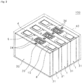
- Fig. 2 is a perspective view of an energy storage apparatus 100 according to the present embodiment
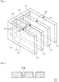
- Fig. 3 is a perspective view of a cooling module 30.
- the energy storage apparatus 100 includes a plurality of energy storage devices 1 arranged in a first direction, a cooling module (cooling unit) 30 for cooling the energy storage device 1, and a case 40 for housing the energy storage device 1 and the cooling module 30.
- a cooling module cooling unit
- a case 40 for housing the energy storage device 1 and the cooling module 30.
- three energy storage devices 1 are housed, but the number of the energy storage devices 1 is not limited to three.
- the case 40 has a box shape and is made of, for example, an insulating material such as a synthetic resin.
- the case 40 protects the energy storage device 1, the cooling module 30 and the like from impact by disposing them at predetermined positions.
- the case 40 is provided with external electrode terminals (not shown) for externally charging the energy storage device 1 and discharging from the energy storage device 1 to the outside.
- the cooling module 30 may be made of a metal having good thermal conductivity and heat resistance, such as aluminum, and may be subjected to an insulating process such as forming an insulating film on the surface.
- the cooling module 30 includes a plate-shaped cooling unit (heat transfer unit) 31, connecting portions 32 and 33 connecting the cooling units 31, and an internal pressure release valve 34.
- the two cooling units 31 are interposed between long side surfaces of adjacent energy storage devices 1 in the first direction, and the other two cooling units 31 abut long side surfaces outside energy storage devices 1 at both ends in the first direction.
- the long side surface is provided so as to extend upward from a long side of a bottom surface of the energy storage device 1 in Fig. 1 and refers to a side surface having the largest area among side surfaces.
- an internal pressure release valve 34 is provided at the center of upper surface of each cooling unit 31, an internal pressure release valve 34 is provided.
- the cooling units 31 may be provided corresponding to the number of the energy storage devices 1, or may be interposed between the energy storage devices 1, and further provided so as to abut the long side surfaces outside the energy storage devices 1 at both ends.
- Installation position of the internal pressure release valve 34 is not also limited to the center of the upper surface of the cooling unit 31.
- the internal pressure release valve 34 can be installed at a position where fire can be effectively prevented when a flame retardant L described later is ejected. As shown in Fig. 2 , the rupture valve 20 of the energy storage device 1 and the internal pressure release valve 34 of the cooling unit 31 may face the same direction. The internal pressure release valve 34 may face upward in the gravity direction.
- the cooling unit 31 is hollow.
- the cooling unit 31 contains a flame retardant L.
- the connecting portion 32 is hollow, and is configured so that gas in the cooling unit 31 to be connected flows through the connecting portion 32.
- the connecting portion 33 is hollow, and is configured so that the flame retardant L in the cooling unit 31 to be connected flows through the connecting portion 33.
- the outer cooling unit 31 can be omitted.
- the number of the energy storage devices 1 is five, four cooling units 31 are disposed between the energy storage devices 1, and the four cooling units 31 are connected by the connecting portions 32 and 33.
- the long side surface of the outer energy storage device 1 is abutted on a side surface of the case 40. The cooling efficiency is better when the outer cooling unit 31 is provided.
- Fig. 4 is a sectional view taken along line IV-IV of Fig. 3 .
- the internal pressure release valve 34 is a circular groove, and as shown in Fig. 4 , the thickness of bottom of the groove is less than the thickness of other parts.
- the internal pressure release valve 34 is formed by cutting, pressing, or the like. When the internal pressure release valve 34 is formed by cutting, a device capable of cutting a curved surface such as a three-dimensional NC is used. When the internal pressure release valve 34 is formed by pressing, the internal pressure release valve 34 is formed as if a marking is printed by a mold having a protrusion.
- the flame retardant L exhibits flame retardancy to flammable gas by being vaporized.
- the flame retardant L preferably has a large heat of vaporization, has corrosion resistance, and does not generate toxic gas.
- the flame retardant L preferably contains at least one of an acyclic fluorinated ether, a fluorinated phosphate ester, and a phosphazene derivative. These have high flame retardancy by being vaporized.
- the acyclic fluorinated ether is more preferably represented by the following formula (1).
- X is F or CF 3
- j, k, m, n, x and y are integers, 0 ⁇ j ⁇ 3, 0 ⁇ k ⁇ 3, 1 ⁇ m ⁇ 3, 0 ⁇ n ⁇ 1, 0 ⁇ x ⁇ 2, and 0 ⁇ y ⁇ 2, and contain at least one fluorine atom.
- HCF 2 CF 2 CH 2 OCF 2 CF 2 H HCF 2 CF 2 OCH 2 CF 3 , CF 3 CF 2 CH 2 OCF 2 CF 2 H, HCF 2 CF 2 CH 2 OCHF 2 , CF 3 CF 2 CH 2 OCF 2 H, (CF 3 ) 2 CHCF 2 OCF 2 H, CF 3 CHFCF 2 CH 2 OCHF 2 and the like, and the like, but are not limited thereto.
- the fluorinated phosphate ester is more preferably represented by the following formula (2).
- j, k, l, m, n, o, x, y and z are integers, 0 ⁇ j ⁇ 3, 0 ⁇ k ⁇ 3, 0 ⁇ l ⁇ 3, 0 ⁇ m ⁇ 1, 0 ⁇ n ⁇ 1, 0 ⁇ o ⁇ 1, 0 ⁇ x ⁇ 2, 0 ⁇ y ⁇ 2, and 0 ⁇ z ⁇ 2, and contains at least one fluorine atom.
- the phosphazene derivative is more preferably represented by the following formula (3).
- R 1 to R 6 represent identical or non-identical hydrogen atoms, halogen atoms, linear or branched alkyl groups having 1 to 10 carbon atoms, alkyl groups having 1 to 10 carbon atoms substituted with a fluorine atom, alkoxy groups having 1 to 10 carbon atoms, or alkoxy groups having 1 to 10 carbon atoms substituted with a fluorine atom.
- the phosphazene derivative is further preferably a fluorine-containing phosphazene derivative in which at least one of R 1 to R 6 is either a fluorine atom, an alkyl group substituted with a fluorine atom, or an alkoxy group substituted with a fluorine atom.
- monoethoxypentafluorocyclotriphosphazene represented by the following chemical formula 3 and monophenoxypentafluorocyclotriphosphazene represented by the following chemical formula 4 are particularly preferable.
- the capacity of the flame retardant L is set based on the cooling unit 31, and an internal capacity of the connecting portions 32 and 33, assumed heat generation temperature of the energy storage device 1, volume when the flame retardant L is vaporized, and the like, so as not to damage the cooling unit 31.
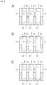
- Fig. 5 is an explanatory diagram illustrating cooling by the cooling module 30 when the energy storage device 1 generates heat.
- cooling module 30 contains the flame retardant L (although water may be contained as an alternative liquid), and the central energy storage device 1 generates heat.
- Heat is conducted from the heated energy storage device 1 to the cooling units 31 and 31 on both sides, and the flame retardant L in the cooling unit 31 evaporates ( Fig. 5A ).
- the flame retardant L evaporates, heat of vaporization is taken away, and the energy storage device 1 is rapidly cooled by an endothermic reaction.
- the liquid amount of the flame retardant L in the cooling unit 31 decreases.
- the gas in the cooling unit 31 flows upward by thermal convection, passes through the connecting portions 32 and 32, and moves to the outer cooling unit 31 having a low temperature ( Fig. 5B ).
- the gas condenses in the outer cooling unit 31, and the liquid amount of the flame retardant L in the outer cooling unit 31 increases.
- the flame retardant L flows to the inner cooling unit 31 through the connecting portion 33, and the liquid amounts of the flame retardant L in the four cooling units 31 become equal ( Fig. 5C ).
- the circulated flame retardant L also absorbs heat generated by the energy storage device 1, vaporizes, and circulates similarly as described above.
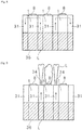
- Fig. 6 is an explanatory diagram illustrating suppression of fire by a flame retardant.
- Fig. 6 shows a state in which the internal pressure release valves 34 of the cooling units 31 on both sides of the energy storage device 1 are opened, and the flame retardant L is released.
- a rupture valve 20 opens, and the flammable component of the volatilized electrolyte solution is released to the outside.
- the flammable component is made flame-retardant by the flame retardant L, so that fire is prevented.
- an energy storage apparatus 100 of the present embodiment includes a plurality of energy storage devices 1, and a cooling unit 31 that is disposed at least between the energy storage devices 1, incorporates a flame retardant L, and cools the energy storage device 1 by heat of vaporization of the flame retardant L.
- the cooling unit 31 is disposed at least between the energy storage devices 1, conduction of heat to an energy storage device 1 adjacent to a heated energy storage device 1 is suppressed. Even when heat is transferred to the adjacent energy storage device 1 not via the cooling unit 31, a long side surface facing the heated energy storage device 1 is cooled by the cooling unit 31. Therefore, chain heat transfer to the energy storage device 1 is suppressed.
- Cooling structure of the cooling module 30 is simple, and the energy storage device 1 can be also cooled even when a small amount of heat is generated.
- the flame retardant L Since the flame retardant L is incorporated in the cooling unit 31, it is vaporized, then liquefied in the cooling unit 31, reused for cooling the energy storage device 1, and efficiently cools the energy storage device 1.
- the flame retardant L exhibits flame retardancy to a flammable gas by being vaporized.
- the flame retardant L absorbs heat and vaporizes from the heated energy storage device 1 and is released from the internal pressure release valve 34, the flame retardant L is mixed with a flammable component released from the energy storage device 1 and the flammable component is made flame-retardant, so that fire is prevented in the energy storage apparatus 100.
- the flame retardant L includes at least one of an acyclic fluorinated ether, a fluorinated phosphate ester, and a phosphazene derivative.
- the flame retardant L has high flame retardancy by being vaporized.
- the cooling module 30 has a connecting portion that connects a plurality of the cooling units 31 so that internal spaces communicate with each other.
- a gas generated by vaporization of the flame retardant L passes through the connecting portions 32 and 33 by thermal convection, and flows to other cooling unit 31.
- the gas is liquefied in the other cooling unit 31 and flows to the one cooling unit 31, and the flame retardant L circulates.
- the flame retardant L is reused for cooling the energy storage device 1, and the energy storage device 1 is efficiently cooled.
- the heated gas flows from one cooling unit 31 to the other cooling unit 31 via the connecting portions 32 and 33, so that a temperature difference between a long side surface in contact with the one cooling unit 31 and a long side surface in contact with the other cooling unit 31 is reduced, in one energy storage device 1, and the temperature difference between the energy storage devices 1 is reduced. Then, by circulation of the gas and the flame retardant L, the temperature difference between the plurality of the energy storage devices 1 can be reduced and the plurality of the energy storage devices 1 can be efficiently cooled. Even when a small amount of heat is generated, which is not abnormal, the heat from the energy storage devices 1 is radiated well by the cooling unit 31, and the temperature difference between the energy storage devices 1 is reduced.
- the cooling unit 31 has an internal pressure release valve 34 that releases internal pressure of the cooling unit 31 when the internal pressure exceeds a predetermined pressure.
- the internal pressure release valve 34 is opened and the gas is released to the outside. The release of the gas prevents the cooling unit 31 from expanding and the energy storage device 1 from being pressed.
- the temperature in the energy storage device 1 rises rapidly, the amount of heat absorbed from the energy storage device 1 increases, and the amount of evaporation of flame retardant L increases.
- the internal pressure reaches a predetermined value or more, the vaporized flame retardant L is released to the outside by opening the cooling unit 31.
- the energy storage device 1 opens, and the flammable component of the volatilized electrolyte solution is released to the outside. The flammable component is made flame-retardant by the flame retardant L, so that fire is prevented.
- a connecting portion may be provided such that a rectangular tube penetrates upper and lower parts of each one end of the four cooling units 31 in the longitudinal direction.
- Fig. 7 is a perspective view of a cooling module 35 according to a second embodiment.
- the same parts as those in Fig. 3 are denoted by the same reference numerals, and detailed description is omitted.
- the cooling module 35 includes four cooling units 31 and a cooling plate 36.
- cooling module 35 unlike the first embodiment in which the four cooling units 31 are connected by the connecting portions 32 and 33, end surfaces 31a of the four cooling units 31 abut the cooling plate 36.
- the cooling unit 31 contains a flame retardant L as in the first embodiment.
- the internal spaces of the cooling unit 31 and the cooling plate 36 may or may not be communicated.
- Fig. 8 is an explanatory diagram of a case where internal spaces are communicated in the present embodiment.
- An energy storage device 1 is inserted between cooling units 31, and the cooling unit 31 and a cooling plate 36 contain a flame retardant L.
- the flame retardant L in the cooling unit 31 which abuts on the energy storage device 1 takes heat of vaporization away from the energy storage device 1 and evaporates, and the energy storage device 1 is quenched.
- the liquid amount of the flame retardant L in the cooling unit 31 decreases.
- the generated gas flows to other cooling unit 31 via the cooling plate 36, and the flame retardant L generated by condensation flows to a cooling unit 31 in which the liquid amount of the flame retardant L is reduced.
- the flame retardant L also absorbs heat to cool the energy storage device 1, and the generated gas circulates as described above.
- the cooling plate 36 also cools a side surface of the energy storage device 1 which abuts thereon.
- the flame retardant L in the cooling unit 31 which abuts on the energy storage device 1 takes heat of vaporization away from the energy storage device 1, and the energy storage device 1 is quenched.
- the generated gas is cooled by the cooling plate 36 and condensed to the flame retardant L.
- the flame retardant L absorbs heat from the energy storage device 1 and vaporizes, and the energy storage device 1 is cooled.
- the cooling module 35 with a simple structure suppresses conduction of heat to the energy storage device 1 adjacent to the heated energy storage device 1, and chain heat transfer to a further adjacent energy storage device 1 is suppressed.
- Fig. 9 is an explanatory diagram illustrating suppression of fire by a flame retardant L.
- each of the energy storage devices 1 is formed in a rectangular parallelepiped shape, and the energy storage apparatus includes a cooling plate 36 that is in contact with a surface different from a long side surface opposed to the cooling unit 31 of each of the energy storage devices 1 to cool the plurality of the energy storage devices 1, and is configured to be thermally conductive between the cooling plate 36 and the cooling unit 31.
- the cooling plate 36 and the cooling unit 31 are integrated so that the flame retardant L or a gas obtained by vaporizing the flame retardant L can be circulated.
- a gas generated by vaporization of the flame retardant L passes through the cooling plate by thermal convection, and flows to other cooling unit 31.
- the gas is liquefied in the other cooling unit 31 and flows to the one cooling unit 31, and the flame retardant L circulates.
- the flame retardant L is reused for cooling the energy storage device 1, and efficiently cools the energy storage device 1.
- the temperature difference between one long side surface and the other long side surface of one energy storage device 1 is reduced, and the temperature difference between energy storage devices 1 is reduced. Then, by circulation of the gas and the flame retardant L, the temperature difference between the plurality of the energy storage devices 1 can be reduced and the plurality of the energy storage devices 1 can be efficiently cooled. Even when a small amount of heat is generated, which is not abnormal, the heat from the energy storage devices 1 is radiated well by the cooling unit 31, and the temperature difference between the energy storage devices 1 is reduced.
- Fig. 10 is a perspective view of a cooling module 37 according to a third embodiment.
- the same parts as those in Fig. 3 are denoted by the same reference numerals, and detailed description is omitted.
- the cooling module 37 of the third embodiment has a configuration in which bottom surfaces 31b of four cooling units 31 of the cooling module 30 of the first embodiment abut on a cooling plate 38.
- the cooling unit 31 contains a flame retardant L (not shown).
- the cooling plate 38 may be configured to be cooled by a cooling device (not shown).
- the flame retardant L in the cooling unit 31 which abuts on the energy storage device 1 evaporates, and the energy storage device 1 is quenched by heat of vaporization at the time of evaporation.
- the generated gas flows through other cooling unit 31, and the flame retardant L generated by condensation flows to a cooling unit 31 in which the liquid amount of the flame retardant L is small.
- the cooling plate 38 cools a bottom surface of the energy storage device 1 and also cools the cooling unit 31.
- the flame retardant L in the cooling unit 31 which abuts on the energy storage device 1 also absorbs heat from the energy storage device 1 and evaporates, and the energy storage device 1 is cooled.
- the cooling module 37 with a simple structure suppresses conduction of heat to the energy storage device 1 adjacent to the heated energy storage device 1, and chain heat transfer to a further adjacent energy storage device 1 is suppressed.
- the internal pressure release valve 34 opens, and the vaporized flame retardant L is released to the outside.
- a rupture valve 20 opens, and the flammable component of the volatilized electrolyte solution is released to the outside.
- the flammable component is made flame-retardant by the flame retardant L, so that fire is prevented.
- Fig. 11 is a perspective view of an energy storage apparatus 101 according to a fourth embodiment.
- the same parts as those in Fig. 2 are denoted by the same reference numerals, and detailed description is omitted.
- the energy storage apparatus 101 does not have connecting portions 32 and 33 that connect cooling units 31, unlike the energy storage apparatus 100 according to the first embodiment.
- the cooling unit 31 is independently disposed between energy storage devices 1 or between the energy storage device 1 and an inner surface of a case 40.
- the cooling unit 31 contains a flame retardant L (not shown).
- the flame retardant L in the cooling unit 31 which abuts on the energy storage device 1 takes heat of vaporization away from the energy storage device 1 and evaporates, and the energy storage device 1 is quenched.
- the generated gas convects is cooled by the outside and/or outside air of the energy storage apparatus 101, and is condensed to the flame retardant L.
- the flame retardant L absorbs heat from the energy storage device 1 and vaporizes, and the energy storage device 1 is cooled.
- the cooling unit 31 is interposed between the energy storage devices 1, as in the first embodiment, the heated energy storage device 1 is cooled by the cooling units 31 on both sides, and heat transfer to an adjacent energy storage device 1 is suppressed. Even when heat is transferred to the adjacent energy storage device 1 not via the cooling unit 31, a long side surface facing the heated energy storage device 1 is cooled by the cooling unit 31. Therefore, chain heat transfer to the adjacent energy storage device 1 is suppressed.
- the internal pressure release valve 34 opens, and the vaporized flame retardant L is released to the outside.
- a rupture valve 20 opens, and the flammable component of the volatilized electrolyte solution is released to the outside.
- the flammable component is made flame-retardant by the flame retardant L, so that fire is prevented.
- a cooling unit (heat transfer unit) disposed between energy storage devices may be in the form of a partition member shown in Fig. 12 .
- a partition member 113 has an inorganic paper sheet 100 mainly composed of inorganic fibers, a bag body 111 containing the inorganic paper sheet in an internal space, and a flame retardant (or water) 112 that is impregnated in the inorganic paper sheet 100 and vaporizes by heating.
- the inorganic paper sheet 100 is a sheet formed by making inorganic fibers into paper, and has a void for holding a liquid between the inorganic fibers.
- the porosity of the inorganic paper sheet 100 may be 45% by volume or more and 80% by volume or less.
- the porosity of the inorganic paper sheet refers to a value obtained by calculating the volume per unit area of the inorganic paper sheet using the thickness measured by a thickness gauge, and calculating the volume of the inorganic fibers per unit area of the inorganic paper sheet from the specific gravity of the inorganic fiber and the weight of the inorganic fiber used per unit area of the inorganic paper sheet, that is calculated as a ratio of the difference between these volumes to the volume per unit area of the inorganic paper sheet.
- the bag body 111 may be formed from a laminate sheet in which an aluminum foil (metal layer) 113 and a resin film (resin layer) 114 are joined.
- a sheet forming the bag body 111 may further have an adhesive layer 15 made of resin on the inner surface of the metal layer 113 so as to enable adhesion by heat sealing.
- the flame retardant or water
- the plurality of the energy storage devices 1 may be laminated in a first direction with a partition member 131 interposed therebetween, and may be held by a holding member such as a case 40 or a restraining member in a state of being pressed in the first direction.
- a case where a positive electrode terminal 4 and a negative electrode terminal 8 of the energy storage device 1 are disposed so as to face upward is described, but the present invention is not limited thereto. Even when the positive electrode terminal 4 and the negative electrode terminal 8 are disposed so as to face sideways, the cooling structure of the present invention can be applied.
- the energy storage device 1 is a lithium ion secondary battery
- the energy storage device 1 is not limited to a lithium ion secondary battery.
- the energy storage device 1 may be other secondary battery having an organic solvent, may be a primary battery, or may be an electrochemical cell such as a capacitor.
- the energy storage apparatus according to the present invention can be particularly suitably used as a power source for vehicles.
- the energy storage apparatus according to the present invention can also be suitably used for industrial applications like an energy storage system (large-scale energy storage system, small-scale home energy storage system), a distributed power supply system combined with natural energy such as solar light and wind power, a power supply system for railways, and an automatic guided vehicle (AGV) power supply system.
- an energy storage system large-scale energy storage system, small-scale home energy storage system
- a distributed power supply system combined with natural energy such as solar light and wind power
- a power supply system for railways and an automatic guided vehicle (AGV) power supply system.
- AGV automatic guided vehicle
Landscapes
- Chemical & Material Sciences (AREA)
- Chemical Kinetics & Catalysis (AREA)
- General Chemical & Material Sciences (AREA)
- Electrochemistry (AREA)
- Engineering & Computer Science (AREA)
- Manufacturing & Machinery (AREA)
- Oil, Petroleum & Natural Gas (AREA)
- Health & Medical Sciences (AREA)
- Public Health (AREA)
- Business, Economics & Management (AREA)
- Emergency Management (AREA)
- Secondary Cells (AREA)
- Battery Mounting, Suspending (AREA)
- Electric Double-Layer Capacitors Or The Like (AREA)
Applications Claiming Priority (3)
| Application Number | Priority Date | Filing Date | Title |
|---|---|---|---|
| JP2017182895A JP7159543B2 (ja) | 2017-09-22 | 2017-09-22 | 蓄電装置 |
| JP2017182894A JP7159542B2 (ja) | 2017-09-22 | 2017-09-22 | 蓄電装置 |
| PCT/JP2018/034535 WO2019059198A1 (ja) | 2017-09-22 | 2018-09-19 | 蓄電装置 |
Publications (2)
| Publication Number | Publication Date |
|---|---|
| EP3671943A1 true EP3671943A1 (de) | 2020-06-24 |
| EP3671943A4 EP3671943A4 (de) | 2020-12-02 |
Family
ID=65809754
Family Applications (1)
| Application Number | Title | Priority Date | Filing Date |
|---|---|---|---|
| EP18859523.5A Pending EP3671943A4 (de) | 2017-09-22 | 2018-09-19 | Stromspeichervorrichtung |
Country Status (3)
| Country | Link |
|---|---|
| EP (1) | EP3671943A4 (de) |
| CN (1) | CN111247686B (de) |
| WO (1) | WO2019059198A1 (de) |
Cited By (1)
| Publication number | Priority date | Publication date | Assignee | Title |
|---|---|---|---|---|
| US12191468B2 (en) | 2019-07-03 | 2025-01-07 | Lg Energy Solution, Ltd. | Battery module, and battery pack and power storage device including same |
Families Citing this family (8)
| Publication number | Priority date | Publication date | Assignee | Title |
|---|---|---|---|---|
| CN111682138A (zh) * | 2020-06-19 | 2020-09-18 | 远景动力技术(江苏)有限公司 | 一种电池模组、电池包和电动车 |
| CN111785890A (zh) * | 2020-08-10 | 2020-10-16 | 厦门金龙联合汽车工业有限公司 | 一种换电电池及换电电池系统 |
| CN112290148B (zh) * | 2020-09-30 | 2021-12-14 | 东风汽车集团有限公司 | 一种具有抗振结构的动力电池包 |
| CN112018302B (zh) * | 2020-10-19 | 2021-05-04 | 江苏时代新能源科技有限公司 | 电池、用电装置、制备电池的方法和设备 |
| EP4235950A3 (de) | 2020-10-19 | 2023-11-01 | Jiangsu Contemporary Amperex Technology Limited | Batterie, stromverbrauchsvorrichtung und verfahren und vorrichtung zur herstellung einer batterie |
| US12062770B2 (en) | 2021-09-20 | 2024-08-13 | GM Global Technology Operations LLC | Thermal barrier component for mitigating thermal runaway in batteries |
| US12095059B2 (en) * | 2021-09-22 | 2024-09-17 | GM Global Technology Operations LLC | Thermal barrier components including hydrates for mitigating thermal runaway in batteries |
| KR20240118156A (ko) * | 2022-02-21 | 2024-08-02 | 컨템포러리 엠퍼렉스 테크놀로지 씨오., 리미티드 | 전지 및 전기 장치 |
Family Cites Families (12)
| Publication number | Priority date | Publication date | Assignee | Title |
|---|---|---|---|---|
| JPS5842873B2 (ja) | 1979-04-06 | 1983-09-22 | 理化学研究所 | セスキテルペン誘導体及びその製造法 |
| JP5092416B2 (ja) | 2007-01-17 | 2012-12-05 | 株式会社Gsユアサ | 非水電解質二次電池 |
| GB0915004D0 (en) * | 2009-08-28 | 2009-09-30 | Ineos Fluor Holdings Ltd | Heat transfer composition |
| PT2659543T (pt) * | 2010-12-29 | 2024-04-30 | Byd Co Ltd | Módulo de bateria, sistema de gestão de temperatura de bateria e veículo compreendendo o mesmo |
| JP5804323B2 (ja) * | 2011-01-07 | 2015-11-04 | 株式会社Gsユアサ | 蓄電素子及び蓄電装置 |
| JP5772428B2 (ja) * | 2011-09-15 | 2015-09-02 | 日産自動車株式会社 | 二次電池の冷却装置 |
| JP6245038B2 (ja) | 2014-03-31 | 2017-12-13 | 株式会社Gsユアサ | 蓄電装置 |
| CN104578435B (zh) * | 2014-12-09 | 2017-02-01 | 超威电源有限公司 | 一种具备冷却效果及消防功能的能量储存系统 |
| JP2016146298A (ja) * | 2015-02-09 | 2016-08-12 | 本田技研工業株式会社 | バッテリ装置 |
| JP2016177934A (ja) * | 2015-03-19 | 2016-10-06 | 株式会社オートネットワーク技術研究所 | 蓄電パック |
| JP6424692B2 (ja) * | 2015-03-19 | 2018-11-21 | 株式会社オートネットワーク技術研究所 | 蓄電パック |
| DE102015118747A1 (de) * | 2015-11-02 | 2017-05-04 | Valeo Klimasysteme Gmbh | Kühlmodul für eine Batterie, Batterie für ein Fahrzeug und Verfahren zur Herstellung eines Kühlmoduls |
-
2018
- 2018-09-19 EP EP18859523.5A patent/EP3671943A4/de active Pending
- 2018-09-19 CN CN201880068859.2A patent/CN111247686B/zh active Active
- 2018-09-19 WO PCT/JP2018/034535 patent/WO2019059198A1/ja not_active Ceased
Cited By (1)
| Publication number | Priority date | Publication date | Assignee | Title |
|---|---|---|---|---|
| US12191468B2 (en) | 2019-07-03 | 2025-01-07 | Lg Energy Solution, Ltd. | Battery module, and battery pack and power storage device including same |
Also Published As
| Publication number | Publication date |
|---|---|
| CN111247686A (zh) | 2020-06-05 |
| CN111247686B (zh) | 2026-01-02 |
| EP3671943A4 (de) | 2020-12-02 |
| WO2019059198A1 (ja) | 2019-03-28 |
Similar Documents
| Publication | Publication Date | Title |
|---|---|---|
| EP3671943A1 (de) | Stromspeichervorrichtung | |
| US11749850B2 (en) | Battery module, battery pack including battery module, and vehicle including battery pack | |
| CA3141137C (en) | So2-based electrolyte for a rechargeable battery cell, and rechargeable battery cell | |
| US9184467B2 (en) | Low molecular weight salts combined with fluorinated solvents for electrolytes | |
| CN101689675B (zh) | 锂二次电池 | |
| JP5681627B2 (ja) | 電解液及びそれを用いたリチウムイオン二次電池 | |
| TW434923B (en) | Lithium secondary battery and liquid electrolyte for the battery | |
| JP7009892B2 (ja) | 蓄電モジュール及び蓄電パック | |
| JPWO2019107560A1 (ja) | 仕切り部材及び組電池 | |
| JP7718534B2 (ja) | 蓄電装置 | |
| US20170244096A1 (en) | Positive electrode for nonaqueous electrolyte secondary battery, and nonaqueous electrolyte secondary battery | |
| WO2013141242A1 (ja) | イオン液体を用いたリチウムイオン二次電池及びリチウムイオン二次電池モジュール並びにこれらの保温装置 | |
| JPWO2019107561A1 (ja) | 仕切り部材及び組電池 | |
| JP4218792B2 (ja) | 非水二次電池 | |
| JP7729442B2 (ja) | 蓄電装置 | |
| JP2003288863A (ja) | 電気化学デバイス | |
| KR101449787B1 (ko) | 안전성이 향상된 이차전지 | |
| KR20240035053A (ko) | 이차전지 모듈, 전지팩 및 이를 포함하는 디바이스 | |
| KR102866065B1 (ko) | 이차 전지용 전지 케이스 및 파우치 형 이차 전지 | |
| US20240186612A1 (en) | Battery pack | |
| Shen et al. | Lithium-ion batteries: From lab to industry and safety | |
| Shi | Using Amines and Alkanes as Thermal-Runaway Retardants for Lithium-Ion Battery |
Legal Events
| Date | Code | Title | Description |
|---|---|---|---|
| STAA | Information on the status of an ep patent application or granted ep patent |
Free format text: STATUS: THE INTERNATIONAL PUBLICATION HAS BEEN MADE |
|
| PUAI | Public reference made under article 153(3) epc to a published international application that has entered the european phase |
Free format text: ORIGINAL CODE: 0009012 |
|
| STAA | Information on the status of an ep patent application or granted ep patent |
Free format text: STATUS: REQUEST FOR EXAMINATION WAS MADE |
|
| 17P | Request for examination filed |
Effective date: 20200317 |
|
| AK | Designated contracting states |
Kind code of ref document: A1 Designated state(s): AL AT BE BG CH CY CZ DE DK EE ES FI FR GB GR HR HU IE IS IT LI LT LU LV MC MK MT NL NO PL PT RO RS SE SI SK SM TR |
|
| AX | Request for extension of the european patent |
Extension state: BA ME |
|
| A4 | Supplementary search report drawn up and despatched |
Effective date: 20201104 |
|
| RIC1 | Information provided on ipc code assigned before grant |
Ipc: H01M 10/625 20140101ALI20201029BHEP Ipc: H01M 10/6569 20140101ALI20201029BHEP Ipc: H01M 10/647 20140101ALI20201029BHEP Ipc: H01M 2/10 20060101ALI20201029BHEP Ipc: H01M 10/653 20140101ALI20201029BHEP Ipc: H01M 10/613 20140101AFI20201029BHEP Ipc: A62C 3/06 20060101ALI20201029BHEP Ipc: H01M 10/6552 20140101ALI20201029BHEP Ipc: H01M 10/6557 20140101ALI20201029BHEP |
|
| DAV | Request for validation of the european patent (deleted) | ||
| DAX | Request for extension of the european patent (deleted) |