EP3671944B1 - Appareil et méthode de contrôle de la température de batteries - Google Patents
Appareil et méthode de contrôle de la température de batteries Download PDFInfo
- Publication number
- EP3671944B1 EP3671944B1 EP19751325.2A EP19751325A EP3671944B1 EP 3671944 B1 EP3671944 B1 EP 3671944B1 EP 19751325 A EP19751325 A EP 19751325A EP 3671944 B1 EP3671944 B1 EP 3671944B1
- Authority
- EP
- European Patent Office
- Prior art keywords
- cooling plate
- temperature value
- temperature
- location
- transport unit
- Prior art date
- Legal status (The legal status is an assumption and is not a legal conclusion. Google has not performed a legal analysis and makes no representation as to the accuracy of the status listed.)
- Active
Links
Images


Classifications
-
- H—ELECTRICITY
- H01—ELECTRIC ELEMENTS
- H01M—PROCESSES OR MEANS, e.g. BATTERIES, FOR THE DIRECT CONVERSION OF CHEMICAL ENERGY INTO ELECTRICAL ENERGY
- H01M10/00—Secondary cells; Manufacture thereof
- H01M10/42—Methods or arrangements for servicing or maintenance of secondary cells or secondary half-cells
- H01M10/48—Accumulators combined with arrangements for measuring, testing or indicating the condition of cells, e.g. the level or density of the electrolyte
- H01M10/486—Accumulators combined with arrangements for measuring, testing or indicating the condition of cells, e.g. the level or density of the electrolyte for measuring temperature
-
- H—ELECTRICITY
- H01—ELECTRIC ELEMENTS
- H01M—PROCESSES OR MEANS, e.g. BATTERIES, FOR THE DIRECT CONVERSION OF CHEMICAL ENERGY INTO ELECTRICAL ENERGY
- H01M10/00—Secondary cells; Manufacture thereof
- H01M10/60—Heating or cooling; Temperature control
- H01M10/61—Types of temperature control
- H01M10/613—Cooling or keeping cold
-
- H—ELECTRICITY
- H01—ELECTRIC ELEMENTS
- H01M—PROCESSES OR MEANS, e.g. BATTERIES, FOR THE DIRECT CONVERSION OF CHEMICAL ENERGY INTO ELECTRICAL ENERGY
- H01M10/00—Secondary cells; Manufacture thereof
- H01M10/60—Heating or cooling; Temperature control
- H01M10/62—Heating or cooling; Temperature control specially adapted for specific applications
- H01M10/625—Vehicles
-
- H—ELECTRICITY
- H01—ELECTRIC ELEMENTS
- H01M—PROCESSES OR MEANS, e.g. BATTERIES, FOR THE DIRECT CONVERSION OF CHEMICAL ENERGY INTO ELECTRICAL ENERGY
- H01M10/00—Secondary cells; Manufacture thereof
- H01M10/60—Heating or cooling; Temperature control
- H01M10/63—Control systems
-
- H—ELECTRICITY
- H01—ELECTRIC ELEMENTS
- H01M—PROCESSES OR MEANS, e.g. BATTERIES, FOR THE DIRECT CONVERSION OF CHEMICAL ENERGY INTO ELECTRICAL ENERGY
- H01M10/00—Secondary cells; Manufacture thereof
- H01M10/60—Heating or cooling; Temperature control
- H01M10/63—Control systems
- H01M10/637—Control systems characterised by the use of reversible temperature-sensitive devices, e.g. NTC, PTC or bimetal devices; characterised by control of the internal current flowing through the cells, e.g. by switching
-
- H—ELECTRICITY
- H01—ELECTRIC ELEMENTS
- H01M—PROCESSES OR MEANS, e.g. BATTERIES, FOR THE DIRECT CONVERSION OF CHEMICAL ENERGY INTO ELECTRICAL ENERGY
- H01M10/00—Secondary cells; Manufacture thereof
- H01M10/60—Heating or cooling; Temperature control
- H01M10/65—Means for temperature control structurally associated with the cells
- H01M10/655—Solid structures for heat exchange or heat conduction
- H01M10/6554—Rods or plates
-
- H—ELECTRICITY
- H01—ELECTRIC ELEMENTS
- H01M—PROCESSES OR MEANS, e.g. BATTERIES, FOR THE DIRECT CONVERSION OF CHEMICAL ENERGY INTO ELECTRICAL ENERGY
- H01M10/00—Secondary cells; Manufacture thereof
- H01M10/60—Heating or cooling; Temperature control
- H01M10/65—Means for temperature control structurally associated with the cells
- H01M10/656—Means for temperature control structurally associated with the cells characterised by the type of heat-exchange fluid
- H01M10/6569—Fluids undergoing a liquid-gas phase change or transition, e.g. evaporation or condensation
-
- H—ELECTRICITY
- H01—ELECTRIC ELEMENTS
- H01M—PROCESSES OR MEANS, e.g. BATTERIES, FOR THE DIRECT CONVERSION OF CHEMICAL ENERGY INTO ELECTRICAL ENERGY
- H01M10/00—Secondary cells; Manufacture thereof
- H01M10/60—Heating or cooling; Temperature control
- H01M10/65—Means for temperature control structurally associated with the cells
- H01M10/659—Means for temperature control structurally associated with the cells by heat storage or buffering, e.g. heat capacity or liquid-solid phase changes or transition
-
- Y—GENERAL TAGGING OF NEW TECHNOLOGICAL DEVELOPMENTS; GENERAL TAGGING OF CROSS-SECTIONAL TECHNOLOGIES SPANNING OVER SEVERAL SECTIONS OF THE IPC; TECHNICAL SUBJECTS COVERED BY FORMER USPC CROSS-REFERENCE ART COLLECTIONS [XRACs] AND DIGESTS
- Y02—TECHNOLOGIES OR APPLICATIONS FOR MITIGATION OR ADAPTATION AGAINST CLIMATE CHANGE
- Y02E—REDUCTION OF GREENHOUSE GAS [GHG] EMISSIONS, RELATED TO ENERGY GENERATION, TRANSMISSION OR DISTRIBUTION
- Y02E60/00—Enabling technologies; Technologies with a potential or indirect contribution to GHG emissions mitigation
- Y02E60/10—Energy storage using batteries
Definitions
- the present disclosure relates to an apparatus and method for battery temperature control.
- a battery module disclosed by KR 10-2017-0107792 A, published on September 26, 2017 which is one of earlier technologies includes a case and a heat sink.
- the heat sink is in direct contact with the lower surface of the case. Heat from the plurality of batteries is discharged through the case and the heat sink, and the batteries are cooled.
- a heat transfer structure such as the heat sink always contacts the case over a predetermined area, and rather, in some cases, efficient battery use may not be achieved.
- efficient battery use may not be achieved.
- the battery when the battery is in an optimum temperature range, the charging/discharging efficiency of the battery increases, but due to the heat sink, it may take a long time to increase the temperature of the battery to the optimum temperature range.
- the temperature of the heat sink is too much high, heat is transferred from the heat sink to the battery, and the battery may be overheated.
- JP 2008 037357 A JPH 09 199882 A and WO 2014/156991 A .
- the present disclosure is designed to solve the above-described problem, and therefore the present disclosure is directed to providing an apparatus and method for effectively controlling the temperature of a battery by selectively bringing a heat transfer structure into contact with part of the battery according to an environment in which the battery is used, the apparatus being very compact and needing few additional space.
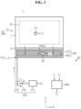
- FIGS. 1 and 2 are diagrams for reference in describing a battery system according to an embodiment of the present disclosure.
- the memory may include at least one type of storage medium of flash memory type, hard disk type, Solid State Disk (SSD) type, Silicon Disk Drive (SDD) type, multimedia card micro type, random access memory (RAM), static random access memory (SRAM), read-only memory (ROM), electrically erasable programmable read-only memory (EEPROM) and programmable read-only memory (PROM).
- flash memory type hard disk type
- SSD Solid State Disk
- SDD Silicon Disk Drive
- multimedia card micro type random access memory
- RAM random access memory
- SRAM static random access memory
- ROM read-only memory
- EEPROM electrically erasable programmable read-only memory
- PROM programmable read-only memory
- the transport unit 220 is coupled to the cooling plate 100, and is configured to selectively move the cooling plate 100 in a direction or a reverse direction along the y-axis.
- the y-axis forms a predetermined angle (for example, a right angle) with the x-axis.
- the control unit 300 may determine the fourth location at the same time as the fourth operation mode is selected or after the fourth operation mode is selected.
- the third location is a preset fixed location at which the cooling plate 100 comes into contact with the outer surface 12 to the maximum extent, while the fourth location is a location that may change depending on at least one of the first temperature value and the second temperature value.
- the control unit 300 may calculate a second transport distance ⁇ Y 1 based on at least one of the first temperature value and the second temperature value. For example, when the first temperature value is greater than the second temperature value, the second transport distance ⁇ Y 1 may be proportional to a difference between the first temperature value and the second temperature value or a difference between the first temperature value and a preset first threshold within a predetermined second range. In this instance, ⁇ Y 1 is equal to y 2 -y 1 or y 1 -y 2 .
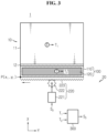
- the temperature control apparatus 20 includes a cooling plate 100, a transport unit 230, a fourth transport unit 240 and a control unit 300.
- the temperature control apparatus 20 may further include at least one of a first temperature sensor 21 and a second temperature sensor 22.
- the transport unit 240 is coupled to the cooling plate 100 through the transport unit 230, and is configured to selectively move the cooling plate 100 in a direction or a reverse direction along the y-axis.
- the fourth transport unit 240 may include a fourth actuator 241 and a second piston 242.
- the fourth actuator 241 may be, for example, a hydraulic cylinder, and is configured to linearly reciprocate the second piston within a predetermined second range along the y-axis.
- the transport unit 220 of FIGS. 3 and 4 may be replaced with the transport unit 240.
- the transport unit 240 may be replaced with the transport unit 220 of FIGS. 3 and 4 .
- the control unit 300 is operably coupled to the transport unit 230 and the fourth transport unit 240.
- the control unit 300 may select any one of a fifth operation mode and a sixth operation mode based on at least one of the first temperature value and the second temperature value at a predetermined time interval or each time a preset condition is satisfied.
- the fifth operation mode is a mode for bringing the cooling plate 100 into contact with the outer surface 12 to the maximum extent.
- the sixth operation mode is a mode for separating the cooling plate 100 from the outer surface 12 or reducing the contact area between the cooling plate 100 and the outer surface 12 so that the contact area is smaller than the contact area of the fifth operation mode.
- the control unit 300 When the fifth operation mode is selected, the control unit 300 outputs a control signal S 5 to the transport unit 230 and the fourth transport unit 240 for commanding the transport unit 230 and the fourth transport unit 240 to move the cooling plate 100 to a fifth location along the x-axis and y-axis respectively.
- the fifth location may be the same as the above-described first location.
- the x-y coordinates of the predetermined point P of the cooling plate 100 may be (x 1 , y 1 ).
- the contact area between the cooling plate 100 and the outer surface 12 is maximized.
- the control unit 300 may determine the sixth location at the same time as the sixth operation mode is selected or after the sixth operation mode is selected.
- the fifth location is a preset fixed location at which the cooling plate 100 comes into contact with the outer surface 12 to the maximum extent
- the sixth location is a location that may change depending on at least one of the first temperature value and the second temperature value.
- the control unit 300 may calculate a third transport distance ⁇ X 2 and a fourth transport distance ⁇ Y 2 based on at least one of the first temperature value and the second temperature value.
- the third transport distance ⁇ X 2 may be proportional to a difference between the first temperature value and the second temperature value or a difference between the first temperature value and a preset first threshold within a predetermined first range.
- the fourth transport distance ⁇ Y 2 may be proportional to a difference between the first temperature value and the second temperature value or a difference between the first temperature value and a preset first threshold within a predetermined second range.
- the first location, the third location and the fifth location may be the same location, and may be referred to as 'reference location'.
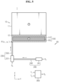
- the outer surface 12 of the battery 10 may include a plurality of first protrusions D 1 .
- Each first protrusion D 1 protrudes from the outer surface 12 toward the cooling plate 100 in a predetermined shape and size.
- Each first protrusion D 1 may extent straight to a predetermined length along the y-axis.
- the cooling plate 100 disposed such that the cooling plate 100 can contact the outer surface 12 may include a plurality of second protrusions D 2 .
- Each second protrusion D 2 protrudes from one surface facing the outer surface 12 of the cooling plate 100 toward the outer surface 12 in a predetermined shape and size.
- Each second protrusion D 2 may extent straight to a predetermined length along the y-axis.
- the plurality of first protrusions D 1 and the plurality of second protrusions D 2 are for increasing the contact area between the outer surface 12 and the cooling plate 100.
- each second protrusion D 2 may be disposed between two adjacent first protrusions of the plurality of first protrusions D 1 . Accordingly, the plurality of first protrusions D 1 and the plurality of second protrusions D 2 are in contact with each other.
- FIG. 8 is a flowchart showing a method related to FIGS. 1 and 2 .
- step S800 the control unit 300 determines the first temperature value indicating the temperature of the battery 10 based on the first temperature signal T 1 from the first temperature sensor 21.
- step S810 the control unit 300 determines whether the first temperature value is equal to or larger than the preset first threshold. When the result of the step S810 is "YES”, step S820 is performed. When the result of the step S810 is "NO”, step S840 is performed.
- step S820 the control unit 300 selects the first operation mode.
- step S830 the control unit 300 outputs the control signal S 1 to the transport unit 210 for commanding the transport unit 210 to move the cooling plate 100 to the first location along the x-axis.
- the first actuator 211 of the transport unit 210 operates in response to the control signal S 1 .
- the cooling plate 100 comes into contact with the outer surface 12 by the preset maximum area.
- step S840 the control unit 300 selects the second operation mode. This is to reduce the contact area between the outer surface 12 and the cooling plate 100 or prevent the cooling plate 100 from coming into contact with the outer surface 12 when the temperature of the cooling plate 100 is not sufficiently lower than the temperature of the battery 10.
- step S850 the control unit 300 outputs the control signal S 2 to the transport unit 210 for commanding the transport unit 210 to move the cooling plate 100 to the second location along the x-axis.
- the first actuator 211 of the transport unit 210 operates in response to the control signal S 2 .
- the cooling plate 100 is moved to the second location, the cooling plate 100 is separated from the outer surface 12.
- FIG. 9 is a flowchart showing another method related to FIGS. 1 and 2 .
- step S900 the control unit 300 determines the first temperature value indicating the temperature of the battery 10 based on the first temperature signal T 1 from the first temperature sensor 21.
- step S905 the control unit 300 determines the second temperature value indicating the temperature of the cooling plate 100 based on the second temperature signal T 2 from the second temperature sensor 22.
- step S910 the control unit 300 determines whether the first temperature value is larger than the second temperature value. When the result of the step S910 is "YES”, step S920 is performed. When the result of the step S910 is "NO”, step S940 is performed.
- step S920 the control unit 300 selects the first operation mode.
- step S930 the control unit 300 outputs the control signal S 1 to the transport unit 210 for commanding the transport unit 210 to move the cooling plate 100 to the first location along the x-axis.
- the first actuator 211 of the transport unit 210 operates in response to the control signal S 1 .
- the cooling plate 100 comes into contact with the outer surface 12 by the preset maximum area.
- step S940 the control unit 300 selects the second operation mode.
- step S950 the control unit 300 outputs the control signal S 2 to the transport unit 210 for commanding the transport unit 210 to move the cooling plate 100 to the second location along the x-axis.
- the first actuator 211 of the transport unit 210 operates in response to the control signal S 2 .
- the cooling plate 100 is moved to the second location, the cooling plate 100 is separated from the outer surface 12.
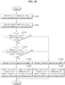
- FIG. 10 is a flowchart showing a method related to FIGS. 3 and 4 .
- step S1000 the control unit 300 determines the first temperature value indicating the temperature of the battery 10 based on the first temperature signal T 1 from the first temperature sensor 21.
- step S1005 the control unit 300 determines the second temperature value indicating the temperature of the cooling plate 100 based on the second temperature signal T 2 from the second temperature sensor 22.
- step S1010 the control unit 300 determines whether the first temperature value is larger than the second temperature value. When the result of the step S1010 is "YES”, step S1015 is performed. When the result of the step S1010 is "NO”, step S1040 is performed.
- step S1015 the control unit 300 determines whether a difference between the first temperature value and the second temperature value is equal to or larger than a preset second threshold (e.g., 3°C).
- a preset second threshold e.g. 3°C.
- step S1020 the control unit 300 selects the third operation mode.
- step S1030 the control unit 300 outputs the control signal S 3 to the transport unit 220 for commanding the transport unit 220 to move the cooling plate 100 to the third location along the y-axis.
- the second actuator 221 of the transport unit 220 operates in response to the control signal S 3 .
- the cooling plate 100 comes into contact with the outer surface 12 by the preset maximum area.
- step S1040 the control unit 300 selects the fourth operation mode. This is to reduce the contact area between the outer surface 12 and the cooling plate 100 and increase the contact area of the outer surface 12 with air when the temperature of the cooling plate 100 is not sufficiently lower than the temperature of the battery 10.
- step S1050 the control unit 300 outputs the control signal S 4 to the transport unit 220 for commanding the transport unit 220 to move the cooling plate 100 to the fourth location along the y-axis.
- the distance between the third location and the fourth location may correspond to the difference between the first temperature value and the second temperature value.
- the second actuator 221 of the transport unit 220 operates in response to the control signal S 4 .
- the cooling plate 100 comes into contact with the outer surface 12 by an area smaller than the maximum area.
- FIG. 11 is a flowchart showing a method related to FIGS. 5 and 6 .
- step S1100 the control unit 300 determines the first temperature value indicating the temperature of the battery 10 based on the first temperature signal T 1 from the first temperature sensor 21.
- step S1105 the control unit 300 determines the second temperature value indicating the temperature of the cooling plate 100 based on the second temperature signal T 2 from the second temperature sensor 22.
- step S1110 the control unit 300 determines whether the first temperature value is larger than the second temperature value. When the result of the step S1110 is "YES”, step S1115 is performed. When the result of the step S1110 is "NO”, step S1140 is performed.
- step S1115 the control unit 300 determines whether a difference between the first temperature value and the second temperature value is equal or larger than a preset third threshold.
- the third threshold may be equal to the second threshold.
- step S1120 the control unit 300 selects the fifth operation mode.
- step S1130 the control unit 300 outputs the control signal S 5 to the transport unit 230 and the transport unit 240 for commanding the transport unit 230 and the transport unit 240 to move the cooling plate 100 to the fifth location along the x-axis and y-axis respectively.
- Each of the third actuator 231 of the transport unit 230 and the fourth actuator 241 of the fourth transport unit 240 independently operates in response to the control signal S 5 .
- the cooling plate 100 comes into contact with the outer surface 12 by the preset maximum area.
- step S1140 the control unit 300 selects the sixth operation mode. This is to reduce the contact area between the outer surface 12 and the cooling plate 100 and increase the contact area of the outer surface 12 with air when the temperature of the cooling plate 100 is not sufficiently lower than the temperature of the battery 10.
- step S1150 the control unit 300 outputs the control signal S 6 to the transport unit 230 and the transport unit 240 for commanding the transport unit 230 and the transport unit 240 to move the cooling plate 100 to the sixth location along the y-axis.
- Each of the third actuator 231 of the transport unit 230 and the fourth actuator 241 of the transport unit 240 independently operates in response to the control signal S 6 .
- the cooling plate 100 comes into contact with the outer surface 12 by an area smaller than the maximum area, or is separated from the outer surface 12.
Landscapes
- Engineering & Computer Science (AREA)
- Manufacturing & Machinery (AREA)
- Chemical & Material Sciences (AREA)
- Chemical Kinetics & Catalysis (AREA)
- Electrochemistry (AREA)
- General Chemical & Material Sciences (AREA)
- Automation & Control Theory (AREA)
- Secondary Cells (AREA)
- Battery Mounting, Suspending (AREA)
Claims (7)
- Appareil (20) de régulation de température de batterie, comprenant :une plaque de refroidissement (100) disposée de sorte que la plaque de refroidissement (100) peut entrer en contact avec une surface extérieure (12) d'une batterie (10) ;un premier capteur de température (21) configuré pour transmettre un premier signal de température indiquant une température de la batterie (10),un second capteur de température (22) configuré pour transmettre un second signal de température indiquant une température de la plaque de refroidissement (100) ;une première unité de transport (210) configurée pour déplacer sélectivement la plaque de refroidissement (100) le long d'un premier axe (x) pour amener la plaque de refroidissement (100) en contact avec la surface extérieure (12) ou pour séparer la plaque de refroidissement (100) de la surface extérieure (12) ; etune unité de régulation (300) couplée de manière opérationnelle à la première unité de transport (210), au premier capteur de température (21) et au second capteur de température (22), et configurée pour déterminer une première valeur de température (T1) et une seconde valeur de température (T2) sur la base du premier signal de température et du second signal de température,dans lequel l'unité de régulation (300) est configurée pour :sélectionner un premier mode de fonctionnement lorsque la première valeur de température (T1) est supérieure à la seconde valeur de température (T2) et une différence entre la première valeur de température (T1) et la seconde valeur de température (T2) est égale ou supérieure à un seuil,délivrer en sortie un premier signal de régulation à la première unité de transport (210) pour ordonner à la première unité de transport (210) de déplacer la plaque de refroidissement (100) vers un premier emplacement lorsque le premier mode de fonctionnement est sélectionné,sélectionner un second mode de fonctionnement (i) lorsque la première valeur de température (T1) est égale ou inférieure à la seconde valeur de température (T2), ou (ii) lorsque la première valeur de température (T1) est supérieure à la seconde valeur de température (T2) et une différence entre la première valeur de température et la seconde valeur de température est inférieure au seuil,calculer une distance de transport (ΔX1) sur la base de la première valeur de température (T1) et de la seconde valeur de température (T2), et déterminer un second emplacement qui est espacé du premier emplacement par la distance de transport (ΔX1) le long du premier axe (x) lorsque le second mode de fonctionnement est sélectionné, etdélivrer en sortie un second signal de régulation vers la première unité de transport (210) pour ordonner à la première unité de transport (210) de déplacer la plaque de refroidissement (100) vers un second emplacement lorsque le second mode de fonctionnement est sélectionné,dans lequel la plaque de refroidissement (100) entre en contact avec la surface extérieure (12) sur une zone maximale prédéfinie lorsque la plaque de refroidissement (100) est déplacée vers le premier emplacement, etdans lequel la plaque de refroidissement (100) est séparée de la surface extérieure (12) lorsque la plaque de refroidissement (100) est déplacée vers le second emplacement.
- Appareil (20) de régulation de température de batterie selon la revendication 1, dans lequel la plaque de refroidissement (100) comporte un matériau de changement de phase.
- Appareil de régulation de température de batterie selon la revendication 1, dans lequel la surface extérieure (12) comporte une pluralité de premières saillies (D1) faisant saillie vers la plaque de refroidissement (100),dans lequel la plaque de refroidissement (100) comporte une pluralité de secondes saillies (D2) faisant saillie vers la surface extérieure (12), etdans lequel la pluralité de secondes saillies (D2) est disposée entre la pluralité de premières saillies (D1) et entre en contact avec la pluralité de premières saillies (D1) lorsque la plaque de refroidissement (100) est déplacée vers le premier emplacement.
- Appareil de régulation de température de batterie selon la revendication 1, dans lequel la distance de transport est proportionnelle à une différence entre la première valeur de température et la seconde valeur de température.
- Appareil (20) de régulation de température de batterie selon la revendication 1, comprenant en outre :
une seconde unité de transport (220) configurée pour déplacer sélectivement la plaque de refroidissement (100) le long d'un second axe (y) qui est différent du premier axe (x). - Système de batterie comprenant l'appareil de régulation de température de batterie selon l'une quelconque des revendications 1 à 5.
- Procédé de régulation de température de batterie à l'aide d'un appareil (20) de régulation de température selon au moins l'une des revendications 1 à 5, le procédé comprenant :la détermination, par l'unité de régulation (300), d'une première valeur de température (T1) indiquant une température de la batterie (10) ;la détermination, par l'unité de régulation (300), d'une seconde valeur de température (T2) indiquant une température de la plaque de refroidissement (100) ;la sélection, par l'unité de régulation (300), d'un premier mode de fonctionnement lorsque la première valeur de température (T1) est supérieure à la seconde valeur de température (T2) ;la sortie, par l'unité de régulation (300), d'un premier signal de régulation vers la première unité de transport (210) pour ordonner à la première unité de transport (210) de déplacer la plaque de refroidissement (100) vers un premier emplacement le long d'un premier axe (x) lorsque le premier mode de fonctionnement est sélectionné ;la sélection d'un second mode de fonctionnement (i) lorsque la première valeur de température (T1) est égale ou inférieure à la seconde valeur de température (T2), ou (ii) lorsque la première valeur de température (T1) est supérieure à la seconde valeur de température (T2) et une différence entre la première valeur de température et la seconde valeur de température est inférieure au seuil ;le calcul d'une distance de transport (ΔX1) sur la base de la première valeur de température (T1) et de la seconde valeur de température (T2), et la détermination d'un second emplacement qui est espacé du premier emplacement par la distance de transport (ΔX1) le long du premier axe (x) lorsque le second mode de fonctionnement est sélectionné, etla sortie, par l'unité de régulation (300), d'un second signal de régulation vers la première unité de transport (210) pour ordonner à la première unité de transport (210) de déplacer la plaque de refroidissement (100) vers le second emplacement le long du premier axe (x) lorsque le second mode de fonctionnement est sélectionné ;dans lequel la plaque de refroidissement (100) entre en contact avec une surface extérieure (12) de la batterie (10) sur une zone maximale prédéfinie lorsque la plaque de refroidissement (100) est déplacée vers le premier emplacement, etdans lequel la plaque de refroidissement (100) est séparée de la surface extérieure (12) lorsque la plaque de refroidissement (100) est déplacée vers le second emplacement.
Applications Claiming Priority (2)
| Application Number | Priority Date | Filing Date | Title |
|---|---|---|---|
| KR1020180015141A KR102350971B1 (ko) | 2018-02-07 | 2018-02-07 | 배터리 모듈의 온도를 조절하기 위한 장치 및 방법 |
| PCT/KR2019/000050 WO2019156352A1 (fr) | 2018-02-07 | 2019-01-02 | Dispositif et procédé de commande de température de batterie |
Publications (3)
| Publication Number | Publication Date |
|---|---|
| EP3671944A1 EP3671944A1 (fr) | 2020-06-24 |
| EP3671944A4 EP3671944A4 (fr) | 2021-01-06 |
| EP3671944B1 true EP3671944B1 (fr) | 2025-07-09 |
Family
ID=67549695
Family Applications (1)
| Application Number | Title | Priority Date | Filing Date |
|---|---|---|---|
| EP19751325.2A Active EP3671944B1 (fr) | 2018-02-07 | 2019-01-02 | Appareil et méthode de contrôle de la température de batteries |
Country Status (9)
| Country | Link |
|---|---|
| US (1) | US11289753B2 (fr) |
| EP (1) | EP3671944B1 (fr) |
| JP (1) | JP6927476B2 (fr) |
| KR (1) | KR102350971B1 (fr) |
| CN (1) | CN110915060B (fr) |
| ES (1) | ES3037875T3 (fr) |
| HU (1) | HUE072432T2 (fr) |
| PL (1) | PL3671944T3 (fr) |
| WO (1) | WO2019156352A1 (fr) |
Families Citing this family (4)
| Publication number | Priority date | Publication date | Assignee | Title |
|---|---|---|---|---|
| CN115249873A (zh) * | 2021-04-28 | 2022-10-28 | 恒大新能源技术(深圳)有限公司 | 汇流排、电池模组及动力电池 |
| JP7779189B2 (ja) * | 2022-04-04 | 2025-12-03 | マツダ株式会社 | 電池ユニット温度管理装置 |
| CN117199490B (zh) * | 2023-10-13 | 2024-11-22 | 江苏烽禾升智能科技有限公司 | 一种电池的电芯与水冷板装配线及装配方法 |
| DE102024111190A1 (de) * | 2024-04-22 | 2025-10-23 | Markus Röschlein | Anordnung zur Übertragung von thermischer Energie einer Energiequelle an einTemperiermedium eines Temperierkreislaufs |
Family Cites Families (16)
| Publication number | Priority date | Publication date | Assignee | Title |
|---|---|---|---|---|
| JPH09199882A (ja) * | 1996-01-22 | 1997-07-31 | Topcon Corp | 温度制御装置 |
| JP3726743B2 (ja) | 2001-11-26 | 2005-12-14 | 日本電気株式会社 | 熱抵抗制御装置 |
| KR100806582B1 (ko) | 2006-07-07 | 2008-02-28 | 엘지전자 주식회사 | 연료 전지의 선택적 스택 단열장치 |
| JP2008037357A (ja) * | 2006-08-09 | 2008-02-21 | Shin Caterpillar Mitsubishi Ltd | 車両のバッテリ温度調整装置 |
| JP2008135191A (ja) | 2006-10-23 | 2008-06-12 | Toyota Motor Corp | 冷却装置及び車両 |
| JP2008204762A (ja) | 2007-02-20 | 2008-09-04 | Toyota Motor Corp | 電源装置 |
| JP4648351B2 (ja) * | 2007-03-30 | 2011-03-09 | 住友ベークライト株式会社 | 伝熱シートおよび放熱構造体 |
| KR101021114B1 (ko) | 2008-11-14 | 2011-03-14 | 현대자동차일본기술연구소 | 차량 구동용 배터리 냉각장치 |
| KR101057556B1 (ko) | 2010-02-03 | 2011-08-17 | 에스비리모티브 주식회사 | 배터리 시스템 및 그 구동 방법 |
| JP2012248299A (ja) | 2011-05-25 | 2012-12-13 | Sanyo Electric Co Ltd | バッテリモジュール、バッテリシステム、電動車両、移動体、電力貯蔵装置および電源装置 |
| JP5648583B2 (ja) | 2011-05-26 | 2015-01-07 | Jfeエンジニアリング株式会社 | 電池システム及び電気自動車 |
| JP2013037919A (ja) | 2011-08-09 | 2013-02-21 | Aisin Seiki Co Ltd | バッテリ温度調整装置 |
| WO2014156991A1 (fr) * | 2013-03-29 | 2014-10-02 | 日本碍子株式会社 | Commutateur thermique, structure de régulation de température, et bloc-batterie |
| DE102014100420A1 (de) | 2014-01-15 | 2015-07-30 | Hans Kunstwadl | Passive Temperaturregelung von Akkus durch zweiphasen Wärmetransport und -speicherung |
| FR3037000B1 (fr) | 2015-06-02 | 2021-09-24 | Saint Gobain Isover | Membrane multicouche |
| KR102172515B1 (ko) | 2016-03-16 | 2020-10-30 | 주식회사 엘지화학 | 배터리 모듈 |
-
2018
- 2018-02-07 KR KR1020180015141A patent/KR102350971B1/ko active Active
-
2019
- 2019-01-02 WO PCT/KR2019/000050 patent/WO2019156352A1/fr not_active Ceased
- 2019-01-02 CN CN201980003622.0A patent/CN110915060B/zh active Active
- 2019-01-02 EP EP19751325.2A patent/EP3671944B1/fr active Active
- 2019-01-02 HU HUE19751325A patent/HUE072432T2/hu unknown
- 2019-01-02 US US16/619,816 patent/US11289753B2/en active Active
- 2019-01-02 JP JP2019571207A patent/JP6927476B2/ja active Active
- 2019-01-02 ES ES19751325T patent/ES3037875T3/es active Active
- 2019-01-02 PL PL19751325.2T patent/PL3671944T3/pl unknown
Also Published As
| Publication number | Publication date |
|---|---|
| JP6927476B2 (ja) | 2021-09-01 |
| PL3671944T3 (pl) | 2025-10-20 |
| HUE072432T2 (hu) | 2025-11-28 |
| CN110915060A (zh) | 2020-03-24 |
| KR20190095756A (ko) | 2019-08-16 |
| ES3037875T3 (en) | 2025-10-07 |
| US11289753B2 (en) | 2022-03-29 |
| WO2019156352A1 (fr) | 2019-08-15 |
| CN110915060B (zh) | 2023-04-18 |
| US20200136211A1 (en) | 2020-04-30 |
| JP2020524883A (ja) | 2020-08-20 |
| KR102350971B1 (ko) | 2022-01-12 |
| EP3671944A1 (fr) | 2020-06-24 |
| EP3671944A4 (fr) | 2021-01-06 |
Similar Documents
| Publication | Publication Date | Title |
|---|---|---|
| EP3671944B1 (fr) | Appareil et méthode de contrôle de la température de batteries | |
| US10283822B2 (en) | Battery module assembly | |
| KR102301195B1 (ko) | 배터리 팩 | |
| US20230023014A1 (en) | Battery Management System, Battery Pack, Electric Vehicle and Battery Management Method | |
| US11476512B2 (en) | Cooling efficiency-enhanced battery module and battery pack comprising same | |
| US11757148B2 (en) | Battery module, and battery pack including the same | |
| EP3806271B1 (fr) | Dispositif d'équilibrage de batterie et bloc-batterie comportant celui-ci | |
| KR20200006404A (ko) | 전기자동차용 전지팩 냉각 시스템 및 이를 이용한 전기자동차용 전지팩 시스템의 냉각 방법 | |
| US20240213577A1 (en) | Battery module, battery thermal management system, and electric device | |
| EP4087018A1 (fr) | Bloc-batterie et dispositif le comprenant | |
| EP4175029A1 (fr) | Structure latérale de bloc batterie pour batterie secondaire d'automobile | |
| US20220029250A1 (en) | Battery Module and Battery Pack Including the Same | |
| EP4156376A1 (fr) | Système de gestion de batterie, procédé de gestion de batterie, bloc-batterie et véhicule électrique | |
| EP3982462B1 (fr) | Système de gestion de batterie, bloc-batterie et procédé de gestion de batterie | |
| EP4068562A1 (fr) | Système de gestion de batterie, procédé de gestion de batterie, bloc-batterie et véhicule électrique | |
| JP7226889B2 (ja) | 電池モジュール、その製造方法および電池モジュールを含む電池パック | |
| JP2024509126A (ja) | バッテリーモジュール | |
| KR102591062B1 (ko) | 배터리 열화 밸런싱 장치 및 방법 | |
| US20230059541A1 (en) | Immersion type battery cooling system including vortex generator | |
| CN114503345A (zh) | 电池模块和包括该电池模块的电池组 | |
| KR20180023637A (ko) | 배터리 모듈 | |
| KR102906907B1 (ko) | 배터리 시스템 및 그 작동 방법 | |
| EP4625666A1 (fr) | Dispositif comprenant un bloc-batterie | |
| US20240304894A1 (en) | Thermal management system for a battery and methods of using the system |
Legal Events
| Date | Code | Title | Description |
|---|---|---|---|
| STAA | Information on the status of an ep patent application or granted ep patent |
Free format text: STATUS: THE INTERNATIONAL PUBLICATION HAS BEEN MADE |
|
| PUAI | Public reference made under article 153(3) epc to a published international application that has entered the european phase |
Free format text: ORIGINAL CODE: 0009012 |
|
| STAA | Information on the status of an ep patent application or granted ep patent |
Free format text: STATUS: REQUEST FOR EXAMINATION WAS MADE |
|
| 17P | Request for examination filed |
Effective date: 20200318 |
|
| AK | Designated contracting states |
Kind code of ref document: A1 Designated state(s): AL AT BE BG CH CY CZ DE DK EE ES FI FR GB GR HR HU IE IS IT LI LT LU LV MC MK MT NL NO PL PT RO RS SE SI SK SM TR |
|
| AX | Request for extension of the european patent |
Extension state: BA ME |
|
| A4 | Supplementary search report drawn up and despatched |
Effective date: 20201203 |
|
| RIC1 | Information provided on ipc code assigned before grant |
Ipc: H01M 10/63 20140101AFI20201127BHEP Ipc: H01M 10/613 20140101ALI20201127BHEP Ipc: H01M 10/48 20060101ALI20201127BHEP Ipc: H01M 10/6569 20140101ALI20201127BHEP Ipc: H01M 10/637 20140101ALI20201127BHEP Ipc: H01M 10/6554 20140101ALI20201127BHEP Ipc: H01M 10/659 20140101ALI20201127BHEP Ipc: H01M 10/625 20140101ALI20201127BHEP |
|
| DAV | Request for validation of the european patent (deleted) | ||
| DAX | Request for extension of the european patent (deleted) | ||
| RAP1 | Party data changed (applicant data changed or rights of an application transferred) |
Owner name: LG ENERGY SOLUTION LTD. |
|
| RAP3 | Party data changed (applicant data changed or rights of an application transferred) |
Owner name: LG ENERGY SOLUTION, LTD. |
|
| GRAP | Despatch of communication of intention to grant a patent |
Free format text: ORIGINAL CODE: EPIDOSNIGR1 |
|
| STAA | Information on the status of an ep patent application or granted ep patent |
Free format text: STATUS: GRANT OF PATENT IS INTENDED |
|
| INTG | Intention to grant announced |
Effective date: 20250417 |
|
| GRAS | Grant fee paid |
Free format text: ORIGINAL CODE: EPIDOSNIGR3 |
|
| GRAA | (expected) grant |
Free format text: ORIGINAL CODE: 0009210 |
|
| STAA | Information on the status of an ep patent application or granted ep patent |
Free format text: STATUS: THE PATENT HAS BEEN GRANTED |
|
| P01 | Opt-out of the competence of the unified patent court (upc) registered |
Free format text: CASE NUMBER: APP_21299/2025 Effective date: 20250506 |
|
| AK | Designated contracting states |
Kind code of ref document: B1 Designated state(s): AL AT BE BG CH CY CZ DE DK EE ES FI FR GB GR HR HU IE IS IT LI LT LU LV MC MK MT NL NO PL PT RO RS SE SI SK SM TR |
|
| REG | Reference to a national code |
Ref country code: GB Ref legal event code: FG4D |
|
| REG | Reference to a national code |
Ref country code: CH Ref legal event code: EP |
|
| REG | Reference to a national code |
Ref country code: IE Ref legal event code: FG4D |
|
| REG | Reference to a national code |
Ref country code: DE Ref legal event code: R096 Ref document number: 602019072296 Country of ref document: DE |
|
| REG | Reference to a national code |
Ref country code: SE Ref legal event code: TRGR |
|
| REG | Reference to a national code |
Ref country code: ES Ref legal event code: FG2A Ref document number: 3037875 Country of ref document: ES Kind code of ref document: T3 Effective date: 20251007 |
|
| REG | Reference to a national code |
Ref country code: NL Ref legal event code: MP Effective date: 20250709 |
|
| REG | Reference to a national code |
Ref country code: HU Ref legal event code: AG4A Ref document number: E072432 Country of ref document: HU |
|
| PG25 | Lapsed in a contracting state [announced via postgrant information from national office to epo] |
Ref country code: PT Free format text: LAPSE BECAUSE OF FAILURE TO SUBMIT A TRANSLATION OF THE DESCRIPTION OR TO PAY THE FEE WITHIN THE PRESCRIBED TIME-LIMIT Effective date: 20251110 |
|
| PG25 | Lapsed in a contracting state [announced via postgrant information from national office to epo] |
Ref country code: NL Free format text: LAPSE BECAUSE OF FAILURE TO SUBMIT A TRANSLATION OF THE DESCRIPTION OR TO PAY THE FEE WITHIN THE PRESCRIBED TIME-LIMIT Effective date: 20250709 |
|
| REG | Reference to a national code |
Ref country code: AT Ref legal event code: MK05 Ref document number: 1812754 Country of ref document: AT Kind code of ref document: T Effective date: 20250709 |
|
| PG25 | Lapsed in a contracting state [announced via postgrant information from national office to epo] |
Ref country code: IS Free format text: LAPSE BECAUSE OF FAILURE TO SUBMIT A TRANSLATION OF THE DESCRIPTION OR TO PAY THE FEE WITHIN THE PRESCRIBED TIME-LIMIT Effective date: 20251109 |
|
| PGFP | Annual fee paid to national office [announced via postgrant information from national office to epo] |
Ref country code: GB Payment date: 20251222 Year of fee payment: 8 |
|
| PG25 | Lapsed in a contracting state [announced via postgrant information from national office to epo] |
Ref country code: NO Free format text: LAPSE BECAUSE OF FAILURE TO SUBMIT A TRANSLATION OF THE DESCRIPTION OR TO PAY THE FEE WITHIN THE PRESCRIBED TIME-LIMIT Effective date: 20251009 |
|
| REG | Reference to a national code |
Ref country code: LT Ref legal event code: MG9D |
|
| PG25 | Lapsed in a contracting state [announced via postgrant information from national office to epo] |
Ref country code: AT Free format text: LAPSE BECAUSE OF FAILURE TO SUBMIT A TRANSLATION OF THE DESCRIPTION OR TO PAY THE FEE WITHIN THE PRESCRIBED TIME-LIMIT Effective date: 20250709 |
|
| PG25 | Lapsed in a contracting state [announced via postgrant information from national office to epo] |
Ref country code: FI Free format text: LAPSE BECAUSE OF FAILURE TO SUBMIT A TRANSLATION OF THE DESCRIPTION OR TO PAY THE FEE WITHIN THE PRESCRIBED TIME-LIMIT Effective date: 20250709 |
|
| PG25 | Lapsed in a contracting state [announced via postgrant information from national office to epo] |
Ref country code: HR Free format text: LAPSE BECAUSE OF FAILURE TO SUBMIT A TRANSLATION OF THE DESCRIPTION OR TO PAY THE FEE WITHIN THE PRESCRIBED TIME-LIMIT Effective date: 20250709 |
|
| PGFP | Annual fee paid to national office [announced via postgrant information from national office to epo] |
Ref country code: FR Payment date: 20251223 Year of fee payment: 8 |
|
| PG25 | Lapsed in a contracting state [announced via postgrant information from national office to epo] |
Ref country code: GR Free format text: LAPSE BECAUSE OF FAILURE TO SUBMIT A TRANSLATION OF THE DESCRIPTION OR TO PAY THE FEE WITHIN THE PRESCRIBED TIME-LIMIT Effective date: 20251010 |
|
| PGFP | Annual fee paid to national office [announced via postgrant information from national office to epo] |
Ref country code: BE Payment date: 20251229 Year of fee payment: 8 |
|
| PGFP | Annual fee paid to national office [announced via postgrant information from national office to epo] |
Ref country code: SE Payment date: 20251223 Year of fee payment: 8 |
|
| PG25 | Lapsed in a contracting state [announced via postgrant information from national office to epo] |
Ref country code: LV Free format text: LAPSE BECAUSE OF FAILURE TO SUBMIT A TRANSLATION OF THE DESCRIPTION OR TO PAY THE FEE WITHIN THE PRESCRIBED TIME-LIMIT Effective date: 20250709 |
|
| PG25 | Lapsed in a contracting state [announced via postgrant information from national office to epo] |
Ref country code: BG Free format text: LAPSE BECAUSE OF FAILURE TO SUBMIT A TRANSLATION OF THE DESCRIPTION OR TO PAY THE FEE WITHIN THE PRESCRIBED TIME-LIMIT Effective date: 20250709 |
|
| PG25 | Lapsed in a contracting state [announced via postgrant information from national office to epo] |
Ref country code: RS Free format text: LAPSE BECAUSE OF FAILURE TO SUBMIT A TRANSLATION OF THE DESCRIPTION OR TO PAY THE FEE WITHIN THE PRESCRIBED TIME-LIMIT Effective date: 20251009 |
|
| PGFP | Annual fee paid to national office [announced via postgrant information from national office to epo] |
Ref country code: HU Payment date: 20260129 Year of fee payment: 8 |
|
| PG25 | Lapsed in a contracting state [announced via postgrant information from national office to epo] |
Ref country code: SM Free format text: LAPSE BECAUSE OF FAILURE TO SUBMIT A TRANSLATION OF THE DESCRIPTION OR TO PAY THE FEE WITHIN THE PRESCRIBED TIME-LIMIT Effective date: 20250709 |
|
| PGFP | Annual fee paid to national office [announced via postgrant information from national office to epo] |
Ref country code: ES Payment date: 20260212 Year of fee payment: 8 |
|
| PG25 | Lapsed in a contracting state [announced via postgrant information from national office to epo] |
Ref country code: DK Free format text: LAPSE BECAUSE OF FAILURE TO SUBMIT A TRANSLATION OF THE DESCRIPTION OR TO PAY THE FEE WITHIN THE PRESCRIBED TIME-LIMIT Effective date: 20250709 |
|
| PGFP | Annual fee paid to national office [announced via postgrant information from national office to epo] |
Ref country code: DE Payment date: 20251222 Year of fee payment: 8 |
|
| PG25 | Lapsed in a contracting state [announced via postgrant information from national office to epo] |
Ref country code: IT Free format text: LAPSE BECAUSE OF FAILURE TO SUBMIT A TRANSLATION OF THE DESCRIPTION OR TO PAY THE FEE WITHIN THE PRESCRIBED TIME-LIMIT Effective date: 20250709 |
|
| PG25 | Lapsed in a contracting state [announced via postgrant information from national office to epo] |
Ref country code: CZ Free format text: LAPSE BECAUSE OF FAILURE TO SUBMIT A TRANSLATION OF THE DESCRIPTION OR TO PAY THE FEE WITHIN THE PRESCRIBED TIME-LIMIT Effective date: 20250709 |
|
| PGFP | Annual fee paid to national office [announced via postgrant information from national office to epo] |
Ref country code: PL Payment date: 20251229 Year of fee payment: 8 |
|
| PG25 | Lapsed in a contracting state [announced via postgrant information from national office to epo] |
Ref country code: EE Free format text: LAPSE BECAUSE OF FAILURE TO SUBMIT A TRANSLATION OF THE DESCRIPTION OR TO PAY THE FEE WITHIN THE PRESCRIBED TIME-LIMIT Effective date: 20250709 Ref country code: SK Free format text: LAPSE BECAUSE OF FAILURE TO SUBMIT A TRANSLATION OF THE DESCRIPTION OR TO PAY THE FEE WITHIN THE PRESCRIBED TIME-LIMIT Effective date: 20250709 |