EP3671973A1 - Élément de couplage pour assurer et fixer un positionnement correct entre un premier élément de connecteur et un second élément de connecteur - Google Patents
Élément de couplage pour assurer et fixer un positionnement correct entre un premier élément de connecteur et un second élément de connecteur Download PDFInfo
- Publication number
- EP3671973A1 EP3671973A1 EP19217174.2A EP19217174A EP3671973A1 EP 3671973 A1 EP3671973 A1 EP 3671973A1 EP 19217174 A EP19217174 A EP 19217174A EP 3671973 A1 EP3671973 A1 EP 3671973A1
- Authority
- EP
- European Patent Office
- Prior art keywords
- connector element
- connector
- coupling
- locking means
- along
- Prior art date
- Legal status (The legal status is an assumption and is not a legal conclusion. Google has not performed a legal analysis and makes no representation as to the accuracy of the status listed.)
- Granted
Links
Images


Classifications
-
- H—ELECTRICITY
- H01—ELECTRIC ELEMENTS
- H01R—ELECTRICALLY-CONDUCTIVE CONNECTIONS; STRUCTURAL ASSOCIATIONS OF A PLURALITY OF MUTUALLY-INSULATED ELECTRICAL CONNECTING ELEMENTS; COUPLING DEVICES; CURRENT COLLECTORS
- H01R13/00—Details of coupling devices of the kinds covered by groups H01R12/70 or H01R24/00 - H01R33/00
- H01R13/62—Means for facilitating engagement or disengagement of coupling parts or for holding them in engagement
- H01R13/639—Additional means for holding or locking coupling parts together, after engagement, e.g. separate keylock, retainer strap
-
- H—ELECTRICITY
- H01—ELECTRIC ELEMENTS
- H01R—ELECTRICALLY-CONDUCTIVE CONNECTIONS; STRUCTURAL ASSOCIATIONS OF A PLURALITY OF MUTUALLY-INSULATED ELECTRICAL CONNECTING ELEMENTS; COUPLING DEVICES; CURRENT COLLECTORS
- H01R13/00—Details of coupling devices of the kinds covered by groups H01R12/70 or H01R24/00 - H01R33/00
- H01R13/62—Means for facilitating engagement or disengagement of coupling parts or for holding them in engagement
- H01R13/627—Snap or like fastening
- H01R13/6275—Latching arms not integral with the housing
-
- H—ELECTRICITY
- H01—ELECTRIC ELEMENTS
- H01R—ELECTRICALLY-CONDUCTIVE CONNECTIONS; STRUCTURAL ASSOCIATIONS OF A PLURALITY OF MUTUALLY-INSULATED ELECTRICAL CONNECTING ELEMENTS; COUPLING DEVICES; CURRENT COLLECTORS
- H01R13/00—Details of coupling devices of the kinds covered by groups H01R12/70 or H01R24/00 - H01R33/00
- H01R13/62—Means for facilitating engagement or disengagement of coupling parts or for holding them in engagement
- H01R13/627—Snap or like fastening
- H01R13/6277—Snap or like fastening comprising annular latching means, e.g. ring snapping in an annular groove
-
- H—ELECTRICITY
- H01—ELECTRIC ELEMENTS
- H01R—ELECTRICALLY-CONDUCTIVE CONNECTIONS; STRUCTURAL ASSOCIATIONS OF A PLURALITY OF MUTUALLY-INSULATED ELECTRICAL CONNECTING ELEMENTS; COUPLING DEVICES; CURRENT COLLECTORS
- H01R13/00—Details of coupling devices of the kinds covered by groups H01R12/70 or H01R24/00 - H01R33/00
- H01R13/64—Means for preventing incorrect coupling
- H01R13/641—Means for preventing incorrect coupling by indicating incorrect coupling; by indicating correct or full engagement
Definitions
- the present invention relates to the field of electrical connectors and in particular relates to a coupling element that ensures and fixes the correct relative positioning between a first and a second connector element. Furthermore, the present invention relates to an electrical connector device comprising such coupling element and a method for ensuring and fixing a coupling between the first connector element and the second connector element.
- the electrical connector device 400 comprises a first connector element 401 and a second connector element 402 that are configured so as to be coupled mechanically along a first direction, which corresponds to a vertical direction of Figure 1 of the present application.
- an elastic fastener 430 is positioned so as to fix the relative positioning between the connector element 401 and the second connector element 402.
- the first connector element 401 and the second connector element 402 are comprised of bodies made of plastic material that carry within them the electric terminals that can be coupled to one another following the mechanical connection between the first connector element 401 and the second connector element 402.
- the elastic fastener 430 is mounted on the first connector element 401 at a grooved portion 405 positioned at a lower part of the connector element 401.
- the elastic fastener 430 comprises a pair of end portions 432 configured so as to be able to slide along a surface of the first connector element 401 and to divaricate with respect to one another so as to be able to be elastically connected to a locking element 420 positioned on the second connector element 402.
- a safety locking member 440 is provided, positioned slidably along the first connector element 401.
- the safety locking member 440 is configured so as to be able to slide along the lateral surface of the connector element 401 so as to be interposed between the lateral wall of the first connector element 401 and the central portion 433 of the elastic fastener 430.
- the aim of the present invention is that of providing a single coupling element configured so as to guarantee a correct positioning of the first connector element and of the second connector element and to fix the first connector element to the second connector element without requiring the presence of a second external additional element that allows such aim to be performed, as instead happens in the state of the art.
- EP 2 876 745 A1 A further connector of the state of the art is known from EP 2 876 745 A1 .
- the present invention is based on the idea of providing a coupling element that makes it possible to both ensure and fix the correct relative positioning between a first connector element and a second connector element.
- a coupling is provided which is configured to ensure and fix the correct relative positioning between a first connector element and a second connector element.
- the first connector element and the second connector element are configured so as to be able to be coupled to one another along the first direction.
- the coupling element comprises a first arched portion, having a first terminal portion and a second terminal portion, and a second arched portion, having a first terminal portion and a second terminal portion, wherein the first terminal portion of the first arched portion is connected to the first terminal portion of the second arched portion.
- the coupling element further comprises a first locking means comprising at least a first projecting element that extends from the first arched portion and is configured so as to be inserted within an opening of the first connector element and a groove of the second connector element for fixing the relative positioning of the first connector element with respect to the second connector element along the first direction.
- the coupling element further comprises a second locking means comprising a closing means positioned at the second terminal portion of the first arched portion and of the second terminal portion of the second arched portion; wherein the closing means is configured so as to fix the second terminal portion of the first arched portion to the second terminal portion of the second arched portion so as to fix the relative positioning between the first connector element and the coupling element along a second direction that is perpendicular to the first direction.
- the term “arched” means any shape that allows an external body to be “embraced”.
- an arched portion may be a portion that joins two different points by means of two or more broken lines or by means of a continuous curved line.
- This solution is also advantageous as it makes it possible to have a single element, represented by the coupling element, able to ensure and fix the correct relative positioning between the first and the second connector element. This is guaranteed by the presence of the first locking means and the second locking means.
- the first locking means is able, thanks to the presence of at least one projecting element, to pass through an opening of the first connector element and a groove of the second connector element so as to be able to fix the relative positioning along a direction that is perpendicular to the insertion direction of the coupling element.
- the fixing of the coupling element to the first connector element is guaranteed, so as to be able to guarantee the relative positioning between the first connector element and the second connector element.
- by locking the movement of the first connector element it will be possible to prevent the uncoupling of the coupling element from the two connector elements.
- such second locking means guarantees obtaining the same function as the safety locking member described in the electrical connector device known in the state of the art.
- a coupling element in which the second locking means further comprises a fixing projection positioned at a terminal portion of the first projecting element of the first locking means and configured so as to lock the relative positioning between the projecting element of said first locking means and said second connector element.
- a coupling element in which the first locking means comprises a first projecting element and a second projecting element, wherein a terminal portion of each of the first projecting element and of the second projecting element comprises a fixing projection configured so as to lock a relative positioning between the projecting elements of the first locking means and the second connector element.
- a coupling element wherein the first projecting element of the first locking means is configured so as to be elastically deformable along a perpendicular direction to the extension direction of the first projecting element.
- a coupling element wherein the closing means of the second locking means comprises a hook closure wherein a male hook portion is positioned preferably at said second terminal portion of said first arched portion and a female hook portion is positioned preferably at said second terminal portion of said second arched portion.
- a coupling element is provided, further comprising a third locking means configured so as to fix the positioning of said coupling element with respect to said first connector element along a circumferential direction of said first connector element, said third locking means comprising a locking protrusion that extends along an internal circumferential surface of said second arched portion. Thanks to the presence of the third locking means, it will be possible to prevent the opening of the coupling element due for example to high vibrations to which a coupling element can be subject.
- a coupling element is provided, wherein the first arched portion is provided integrally with the second arched portion, wherein a connection portion is configured so as to connect the first terminal portion of the first arched portion to the first terminal portion of the second arched portion.
- each of the first arched portion and the second arched portion comprises a semicircular body.
- an electrical connector device comprising a coupling element according to any one of the preceding embodiments and a first connector element and a second connector element.
- the first connector element and the second connector element bearing respective electrical terminals with respective bodies that can be coupled to one another being configured so as to be able to be coupled to one another along the first direction.
- the first connector element comprising a first lateral opening configured so as to be able to allow the passage of the first projecting element of the first locking means.
- the second connector element comprising a first lateral groove configured so as to house the first projecting element of the first locking means, the first lateral groove comprising a wall perpendicular to the first direction and positioned above the projecting element of said first locking means so as to fix the relative positioning of the first connector element with respect to the second connector element along the first direction; wherein the closing means of the second locking means is configured so as to rest the coupling element against an outer surface of the first connector element so as to fix the coupling element to the first connector element.
- This solution is particularly advantageous as it allows the connection to be made between the first connector element and the second connector element thanks to the presence of a single coupling element able to perform a double function: that of ensuring the relative positioning between the first connector element and the second connector element and that of fixing such connection so as to be able to prevent a possible uncoupling between the two elements.
- the first locking means is able to lock the relative movement along the first direction between the first and the second connector element, thanks to the insertion of projections along a perpendicular direction with respect to the first direction, so that an abutment surface positioned above the projecting element of the first locking means is able to prevent the coupling element from being translated along the first direction and therefore prevent a relative movement between the second connector element and the coupling element along the first direction.
- the locking of the relative movement along the second direction is guaranteed thanks to the fact that the closing means of the second locking means is configured so as to rest the outer surface of the first connector element, so as to be able to be engaged therewith.
- an electrical connector device wherein the first connector element comprises a support groove positioned along an outer lateral wall of the first connector element and extending along a perpendicular direction to the first direction, the support groove is configured so as to be coupled with a locking protrusion of the second arched portion so as to lock a circumferential positioning between the second arched portion of the coupling element and the first connector element.
- This solution is particularly advantageous as it allows uncoupling to be prevented which could happen because of the vibrations to which the electrical connector device is subject. In fact, it could happen that, because of vibrations, the closure hook of the second locking means opens.
- the presence of such support groove and of such locking protrusion allows the vibrations to which the second locking means is subjected to be dampened, thus reducing the probability of the second locking means being able to open.
- an electrical connector device in which the first connector element further comprises a second lateral groove configured so as to house the first locking means, wherein the second groove comprises a wall perpendicular to the first direction and positioned above the first locking means so as to fix the relative positioning of the first connector element with respect to the second connector element along the first direction.
- an electrical connector device in which the first and the second lateral groove have an open terminal portion configured so as to allow fixing projections of the second locking means to be fixed to the first and to the second lateral groove.
- This solution is particularly advantageous as it allows the grooves of the second conductor element to be used both for the locking of the coupling element along the first direction and for the locking of the coupling element along the second direction.
- an electrical connector device wherein the first connector element and the second connector element have a substantially cylindrical shape.
- cylindrical identifies any curve having a cylindrical surface (e.g. an elliptical cylinder or a parabolic cylinder).
- a method for ensuring and fixing a coupling between a first connector element and a second connector element comprising the following steps:
- the method defined in the previous paragraph is realised with a coupling element according to any one of the embodiments defined in the previous paragraphs.
- a coupling is provided which is configured to ensure and fix the correct relative positioning between a first connector element and a second connector element, the first connector element and the second connector element are configured so as to be able to be coupled to one another along a first direction.
- the coupling element comprises: a main body, a first locking means that comprises at least one projecting element that extends from the main body and is configured so as to be inserted within an opening of the first connector element and a groove of the second connector element to fix the relative positioning of the first connector element with respect to the second connector element along the first direction, a second locking means comprising a pair of projecting elements that are positioned on opposite sides in the width direction of the main body and that are configured to fix the relative positioning between the coupling element and the first connector element along a second direction that is perpendicular to the first direction.
- This solution is particularly advantageous as it makes it possible to have a single element, represented by the coupling element, able to ensure and fix the correct relative positioning between the first and the second connector element.
- the first locking means is able, thanks to the presence of at least one projecting element, to pass through an opening of the first connector element and a groove of the second connector element so as to be able to fix the relative positioning along a direction that is perpendicular to the insertion direction of the coupling element.
- the fixing of the coupling element to the first connector element is guaranteed, so as to be able to guarantee the relative positioning between the first connector element and the second connector element.
- the second locking means guarantees obtaining the same function as the safety locking member described in the electrical connector device known in the state of the art.
- a coupling element wherein the pair of projecting elements of the second locking means is represented by a pair of elastically deformable elements and configured so as to be able to press on the outer surface of the first connector element.
- each of the projecting elements of the second locking elements has an opening positioned at a distal portion of the projecting elements, wherein the opening extends along a longitudinal direction of the projecting elements. Thanks to this configuration it is effectively possible to use the projecting elements of the second locking means to mechanically couple the coupling element to the outer surface of the first connector element. In fact, thanks to the presence of the opening positioned at a distal portion, such distal portion can be coupled for example to the projections positioned on the outer lateral surface of the first connector element so as to fix the opening of the projecting elements to such lateral projections. Furthermore, the longitudinal extension of the opening of the projecting elements of the second locking means allows such opening to be used also as a positioning groove able to guide the coupling element in a precise position with respect to the lateral surface of the first connector element.
- a coupling element wherein the first locking means comprises at least three projecting elements positioned along a width direction of the main body and that extend from the main body. Thanks to this solution, it is possible to have at least three different positions at which the coupling element fixes the relative positioning of the first connector element with respect to the second connector element along the first direction. This means that the fixing is more stable fixing as it is more uniform and distributed across various points.
- a coupling element wherein the first projecting element is positioned at a central position of the main body and a second and third projecting element are positioned symmetrically opposite with respect to the first projecting element along a width direction of the coupling element.
- a coupling element wherein the second and the third projecting element of the first locking means have a distal surface turned towards the first projecting element that is at least partially curved. Thanks to this configuration it is possible to use the second and the third projecting element for entering into lateral grooves, for example of a circular or oval element, without having the need to have to in some way perforate the oval or circular body as it will be sufficient to simply provide a groove placed on the lateral surface of the oval or circular body and such curved portion can "adapt" to the curved surface, thus "embracing” the curved portion of the groove.
- an electrical connector device comprising a coupling element according to any one of the preceding embodiment and a first connector element and a second connector element.
- the first connector element and the second connector element bear respective electrical terminals with respective bodies that can be coupled to one another and are configured so as to be able to be coupled to one another along the first direction.
- the first connector element comprises a first lateral opening configured so as to be able to allow the passage of the first projecting element of the first locking means.
- the second connector element comprises a first lateral groove configured so as to house the first projecting element of the first locking means in which the first lateral groove comprises a perpendicular wall to the first direction and positioned above the projecting element of the first locking means, so as to fix the relative positioning of the first connector element with respect to the second connector element along the first direction.
- the pair of projecting elements of the second locking means is configured so as to press the coupling element against an outer surface of the first connector element so as to fix the coupling element to the first connector element.
- the first locking means is able to lock the relative movement along the first direction between the first and the second connector element, thanks to the insertion of projections along a perpendicular direction with respect to the first direction, so that an abutment surface positioned above the projecting element of the first locking means is able to prevent the coupling element from being translated along the first direction and therefore prevent a relative movement between the second connector element and the coupling element.
- the locking of the relative movement along the second direction is guaranteed thanks to the fact that the projecting elements of the second locking means are configured so as to press the outer surface of the first connector element, so as to be able to be engaged therewith.
- the first connector element comprises a pair of first lateral projections positioned on opposite lateral portions of the first connector element and a pair of second lateral projections positioned on opposite lateral portions of the first connector element, wherein the pairs of first projections and of second projections are configured so as to be engaged with the pair of projecting elements of the second locking means.
- the pair of first projections is configured so as to guarantee a pre-mounting of the coupling element on the first connector element and the pair of second projections is configured so as to allow the fixing of the coupling element to the first connector element.
- an electrical connector device wherein the extension of the pair of first lateral projections along the first direction is shorter than the extension of the pair of second lateral projections along the first direction and wherein the longitudinal opening of each of the second locking means has a height along a perpendicular direction to the longitudinal direction of the opening that varies along the longitudinal direction of the opening; wherein the height at a terminal portion of the projecting elements is greater with respect to the height at a base portion of the projecting elements so as to be able to engage the longitudinal opening of each of the second locking means first with the pair of first lateral projections and then with the pair of second lateral projections.
- the height along the perpendicular direction to the longitudinal direction of the opening has two different values along the longitudinal direction of the opening; a value that is constant along the longitudinal direction at a terminal portion of the projections and that is greater than a value that is constant along the longitudinal direction at a base portion of the projecting elements.
- the height at the terminal portion is greater, it will be possible to effectively and precisely guide the coupling element with respect to the outer lateral surface of the first connector element as, preferably, the height at the base portion along the longitudinal direction of the projecting elements of the second locking means is preferably the same as the height of the pair of first projections so that the relative position between the coupling element and the first connector element is a predetermined position.
- an electrical connector device in which the first connector element further comprises a second lateral groove and a third lateral groove each configured so as to house the first locking means, wherein each of the second and third groove comprises a wall perpendicular to the first direction and positioned above the first locking means so as to fix the relative positioning of the first connector element with respect to the second connector element along the first direction.
- an electrical connector device wherein the first connector element and the second connector element have a substantially circular outer side surface.
- a method for ensuring and fixing a coupling between a first connector element and a second connector element, wherein the method comprises the following steps:
- a method is provided in which the coupling element is pre-mounted onto the first connector element before the first connector element is coupled to the second connector element.
- a method wherein in the case in which the coupling element is inserted into the groove of the second connector element for more than a predetermined length, the coupling element is configured to prevent the coupling between the first connector element and the second connector element.
- This solution is particularly advantageous as it allows the coupling element to be used also to guarantee the correct positioning.
- the one or more projections of the first locking means will prevent the first connector element and the second connector element from coupling with one another.
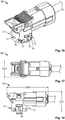
- Figures 2 and 3 show two three-dimensional views of a coupling between a first connector element 10 and a second connector element 20, with a coupling element 30 configured so as to fix the mechanical coupling between the first conductor element 10 and the second connector element 20 according to a first embodiment of the present invention.
- first connector element 10 and the second connector element 20 are elements intended to be electrically connected to one another through mechanical type operations actuated by a user.
- the connector elements 10 and 20 are formed by respective bodies of preferably elastic material that supports and houses respective electrical terminals that can be coupled to one another following the mechanical connection, and therefore the coupling, between the two elements 10 and 20.
- first direction R1 a pressure exerted on the first connector element 10 above the second connector element 20 along the direction R1 shown in the figure
- the first connector element 10 can be a plug connector whereas the second connector element 20 can be an external header connector.
- the present invention can also operate in the event in which the first connector element is made of an external header connector and the second connector element is made of a plug connector.
- the first connector element 10 like the second connector element 20 is made, as mentioned, of plastic material, for example PA46-GF30 plastic.
- the second connector element has a height D12 that can preferably be equal to 12.5 mm. Furthermore, as shown in the view from above of Figure 15 , the width D13 of the second connector element 20 is preferably equal to 31 mm whereas the depth D14 thereof is preferably equal to 20.3 mm.
- the depth D15 of the first connector element is preferably equal to 19 mm whereas the length D16 and the height D17 are preferably 49 mm and 24 mm respectively.
- the mechanical connection is made by means of a coupling element 30 that is inserted through the first connector element 10 and the second connector element 20 along a direction R2 (hereinafter called "second direction R2") which is perpendicular to the first direction R1.
- the coupling element 30 is preferably made of plastic material, e.g. PA46-GF30 plastic.
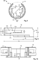
- the coupling element 30 comprises a main body 33 from which a series of projecting elements extend.
- a pair of projecting elements 31 and 32 extends from lateral portions of the main body 33 and is configured so that the projecting elements 31 and 32 are elastically deformable along a parallel plane to the plane on which the coupling element 30 lies so that the two projections 31 and 32 can be moved towards and away from one another by exercising pressure thereon.
- two openings 37 and 38 are made, which extend along a longitudinal direction of the projecting elements 31 and 32.
- the pair of projecting elements 31 and 32 form, together with the openings 37 and 38, a "second locking means".
- the coupling element 30 comprises three projecting elements 34, 35 and 36 which substantially extend perpendicularly from the main body 33.
- the projecting elements 31 and 32 were omitted from such figure so as to be able to show the arrangement of the projections 34 and 35 more clearly.
- the three projecting elements 34, 35, 36 form a first locking means.
- the projecting element 36 will simply be called the first projection of the first locking means whereas the projecting elements 34 and 35 will be respectively referred to as second and third projection of the first locking means.
- the three projections 34, 35, 36 of the first locking means are fixed stably to the main body therefore preferably having high rigidity in spite of the elasticity of the pair of projecting elements 31 and 32 and of the second locking means.
- the first projection 36 is positioned centrally in a lower portion of the main body 33 whereas the second and third projection 34 and 35 are always positioned in a lower portion of the main body but symmetrically opposite with respect to the first projection 36.
- the longitudinal extension of the second and third projection is, as will be described below, much higher with respect to the longitudinal extension of the first projection 36 so that the second and the third projection 34 and 35 can reach further portions of external elements.
- the second and third projection 34 and 35 have a curved inner surface.
- inner surface of the second and third projection 34 and 35 means a surface facing towards the first projection 36.
- Figure 6 shows a detail of a view from above of the coupling element 30 in which all the projections 31, 32, 34, 35, 36 of the first and second locking means can be seen.
- the coupling element 30 is perfectly symmetrical with respect to a central axis, at which the first projection 36 of the first mounting means is placed.
- Figure 7 shows a detail of the openings 37 and 38 of the pair of projecting elements 31 and 32.
- the opening 38 preferably has the same conformation as the opening 37.
- the height of the opening 37 along a longitudinal length of the projecting element 32 varies: a first portion 37a has a height along a perpendicular direction to the longitudinal direction of the projecting element 32 that is shorter with respect to the height of the second portion 37b positioned closer to the distal portion of the projecting element 32.
- first portion 37a and the second portion 37b there is preferably a step 37c perpendicular to the longitudinal direction of the projecting element 32, which allows the passage from the first portion 37a to the second portion 37b.
- the shape of the coupling element 30 seen in plan view is of a substantially circular element wherein a portion of the circle is removed to allow the coupling element 30 to be coupled with an external body.
- the distance D2 between an outer portion of the second projection 34 and an outer portion of the third projection 35 of the first locking means is preferably equal to 14.7 mm.
- the first projection 36 has a substantially quadratic shape and has a length D3 preferably equal to 2 mm and a width D4 preferably equal to 2.1 mm.
- the pair of projecting elements 31 and 32 has a height D5 preferably equal to 4.8 mm.
- the distal portion 37b (second portion) of the opening 37 has a height D6 preferably equal to 2.1 mm whereas the first portion 37a of the opening 37 preferably has a height D9 equal to 1.7 mm.
- the step 37c between the first portion 37a and the second portion 37b which is preferably equal in a lower portion and an upper portion of the opening 37, will preferably be equal to 0.2 mm.
- the length D7 of the second and of the third projection 34 and 35 of the first locking means is preferably equal to 13 mm whereas the total extension D8 of the pair of projecting elements 31 and 32 of the second locking means is preferably equal to 19 mm.
- the total height D10 of the coupling element 30 is preferably equal to 5.8 mm.
- the first projection 34 of the first locking means which, as previously mentioned, is substantially quadratic shaped, has a height D11 preferably of 2.2 mm.
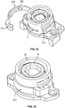
- the second connector element 20 can have numerous variations with respect to what has been described up to now, as the present invention is not limited to this particular embodiment of the second connector element 20 rather, as will become clearer from the following description, it relates to a coupling element that guarantees the coupling and fixing between the first connector element and the second connector element.
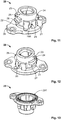
- the second connector element 20 comprises a base 29 on which a substantially cylindrical body is placed having a plurality of protrusions on the outer surface thereof. It is clear that, for example, the base 29 can have any other shape able to allow the coupling of the second connector element 20 to an external element.
- the presence of the protrusions guarantees for the coupling element 30 to fix a positioning along the first direction R1 between the first connector element 10 and the second connector element 20.
- protrusions 24 and 25 On the cylindrical lateral surface 23 there are two symmetrically opposite protrusions 24 and 25 positioned at about half the height of the cylindrical lateral surface 23. Protrusions 21 and 22 are arranged below such protrusions.
- the second and third projection 34 and 35 of the first locking means are configured so as to be interposed between the protrusions 21, 24 and 22, 25, respectively. In this way the curved portion of the second and third projection 34 and 35 will contact the outer surface 23 of the second connector element positioned between the protrusions 24 and 25 and the protrusions 21 and 22.
- an upper surface of the second and third projection 34 and 35 (which preferably have a flat shape) will abut with a lower surface of the protrusions 24 and 25, so that the coupling element 30 cannot move along the first direction R1 with respect to the second connector element 20.
- a further protrusion 266 placed substantially at the same height as the protrusions 24 and 25 and configured so as to be able to house the first projection 36 of the first locking means.
- the protrusions 21 and 24 form a first groove 27 comprised between the upper wall of the protrusion 21, the lateral wall 23 and the lower wall of the protrusion 24. Furthermore, the protrusions 22 and 25 form a second groove 28 formed by the upper wall of the protrusion 22 of the lateral wall 23 and the lower wall of the protrusion 25. Additionally, the protrusion 26 forms a groove 266 below. Such groove will be formed by the lower wall of the protrusion 26 and the upper wall of the base 29.
- sealing element 201 may be placed to allow the seal between the second connector element 20 and an element placed below.
- sealing element 201 is preferably made of rubber by means of a generic silicone.
- Figure 16 shows a three-dimensional view of the first connector element 10.
- first connector element 10 like the second connector element 20, has an outer lateral surface 18 that is substantially cylindrical.
- a pair of first projections 11, 12 and a pair of second projections 12, 13 are placed on the outer surface, which project outside the lateral surface 18.
- the height of the projections 11, 12 of the first pair of projections along the first direction R1 is less than the height of the projections 13, 14 of the second pair of projections.
- the lateral surface 18 of the first connector element 10 comprises three openings 15, 16, 17 configured so as to allow the projections 34, 35, 36 of the first locking means to pass through them. Therefore, such openings shall be found in positions corresponding to the three projections 34, 35, 36 of the first locking means.
- the number of projections of the first locking means is different from three, the number of openings positioned on the outer lateral surface 18 will preferably be equal to the number of projections of the first locking means.
- the first opening 16 will be at a central position and the openings 15, 17 will be configured so as to house the second projection and the third projections 34 and 35 respectively and will therefore be placed symmetrically opposite with respect to the first opening 16.
- a sealing element 19 is preferably placed, represented by a rubber projection (made of a generic silicone) able to isolate the area of the electrical connection from the outside.
- a rubber projection made of a generic silicone
- Such element can prevent dust, damp and water or other fluids from penetrating into the electrical connection, preventing compromising the electrical functionality of the connection.
- the coupling element 30 is pre-mounted on the outer surface 18 of the first connector element 10 by means of the interaction between the openings 37 and 38 of the pair of projecting elements 31 and 32 and the pair of first projections 11 and 12 positioned on the outer surface 18 of the first connector element 10.
- first connector element 10 to be provided with the coupling element 30 pre-mounted thereon so as to proceed with the coupling of two different elements from one another: the pair formed by the connector element 10 and the coupling element 30 with the second connector element 20.
- the pair formed by the first connector element 10 and by the coupling element 30 is moved with respect to the second connector element 20 along the first direction R1.
- the correct final positioning between the first connector element 10 and the second connector element 20 will be terminated precisely by the coupling element 30 which will be able to fix the relative positioning between the first connector element 10 and the second connector element 20 only in the event in which the relative position between the first connector element 10 and the second connector element 20 is a predetermined position.
- the coupling element 30 will be able to be translated from the pre-mounting position shown in Figure 2 to the final position shown in Figure 3 wherein the coupling element 30 is in a fixing position, wherein the openings 37 and 38 are fixed to the pair of second projections 13 and 14 positioned on the outer lateral surface 18 of the first connector element 10.
- the second connector element 20 has been omitted such as to be able to more clearly represent the coupling between the first connector element 10 and the coupling element 30.
- Figure 19a shows a previous state to the coupling wherein the first connector element 10 and the coupling element 30 are completely uncoupled from one another.
- the coupling element 30 reaches a pre-mounting position, in which it is pre-mounted on the first connector element 10 through a coupling of the pair of first projections 11 and 12 with the openings 37, 38 of the pair of projecting elements 31 and 32.
- the pair formed by the first connector element 10 and the coupling element 30 can be coupled to the second connector element 20.
- the present invention is not limited to this particular method.
- the mechanical coupling with the second connector element 20 takes place.
- the coupling element 30 has been translated along the direction R2 so that the projections 34, 35, 36 of the first locking means have penetrated into the grooves 27, 28, 266 of the second connector element.
- the first projection 36 of the first locking means is inserted through the opening 16 positioned on the outer lateral surface 18 of the first connector element 10.
- the openings 37, 38 of the pair of projecting elements 31 and 32 are coupled in a fixed way to the pair of second projections 13 and 14.
- Figure 20 shows a sectional view of the state in which the coupling element 30 is fixed to the first connector element 10 (state shown in Figure 19c ), so as to lock the relative positioning between the first connector element 10 and the second connector element 20.
- the projections 34, 35, 36 of the first locking elements are inserted into the grooves 7, 28, 266 of the second connector element 20 and the pair of projecting elements 31, 32 of the second locking means is fixed to the pair of second projections 13, 14 of the first connector element 10.
- Figure 21 shows a particular feature of the present embodiment.
- the coupling element 30 is pre-mounted on the first connector element 10 before the coupling takes place with the second connector element 20
- Figure 21a shows instead a state in which the coupling element 30 and the first connector element 10 are positioned correctly in which the connection can take place with the second connector element 20.
- the coupling takes place between a first connector element 10 and a second connector element 20 having analogous features to those of the first embodiment.
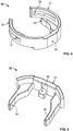
- the substantial difference between the first and the second embodiment is the particular shape of the coupling element 300 which, in this case, has slightly different features, which will be explained in detail in the following description.
- the electrical connector device 101 comprises: a first connector element 10, a second connector element 20 and a coupling element 300 configured so as to ensure and fix the coupling between the first connector element 10 and the second connector element 20.
- the coupling element 300 is preferably made of plastic material, e.g. PA46-GF30 plastic.
- the first connector element 10 it is preferable for the first connector element 10 to have a longitudinal support groove 2 positioned along a circumferential surface of the outer lateral surface 18 of the first connector element 10 and a lateral opening 16 (shown in Figure 31 ).
- the coupling element 300 is configured so as to "embrace" the outer lateral surface 18 of the first conductor element 10.
- the coupling element 300 comprises a first arched portion 301 and a second arched portion 302, connected to one another by a connection portion 303 configured so as to allow a first terminal portion of the first arched portion 301 to be connected to a first terminal portion of the second arched portion 302.
- the first arched portion 301 comprises a male hook portion 316 and the second arched portion 302 has a female hook portion 323 configured so as to be coupled mechanically to the male hook portion 316.
- connection portion 303 has two different shapes.
- Figure 24 shows a connection portion 303 formed integrally with the first arched portion 301 and the second arched portion 302, so that the coupling element 300 forms an integral element.
- Figure 25 shows an additional connection portion 303 that connects the first arched portion 301 with the second arched portion 302 so as to connect them to one another.
- the coupling element 300 can be formed integrally or formed by two distinct and separate bodies which are coupled to one another by means of the connection portion 303.
- connection portion 303 is configured so as to allow the relative displacement between the first arched portion 301 and the second arched portion 302.
- the first arched portion 301 forms a first semi-circle and the arched portion 302 forms a second semi-circle.
- the first arched portion 301 forms a larger portion of a semi-circle (an arc of a circle or ellipse)
- the second arched portion 302 forms a smaller portion of a semi-circle (an arc of a circle or ellipse) or vice versa.
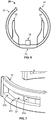
- the first arched portion 301 comprises a first semi-circular body 317 on which a base portion 311 is installed on which a first positioning projection 312 and a second positioning projection 313 are installed which extend from it along an at least partially perpendicular direction from such base portion 311.
- the positioning projections 312, 313 are projections that allow, as will be illustrated below, the correct positioning to be obtained between the first connector element 10 and the second connector element 20.
- the first positioning projection 312 and the second positioning projection 313 have an at least partially arched inner surface, so as to be able to "embrace" an external body, for example elliptical or cylindrical.
- the outer surface will have an arched surface.
- inner surface means a surface turned towards the first positioning projection 312 or towards the second positioning projection 313 and outer surface means a surface opposite it.
- the upper terminal portion of the first positioning projection and of the second positioning projection 312, 313 each comprise a fixing projection 314, 315 which, as will become clearer in the continuation of the description, allows the coupling of the coupling element 300 with the connector element 20. As shown in the figure, such fixing projection is positioned at an upper terminal portion of the positioning projections.
- the second arched portion 302 also comprises a second semicircular body 321 on which a locking protrusion 322 is placed, configured so as to extend along the circumference of the second semicircular body 321.
- Such locking protrusion 322 is preferably in a central portion along the first direction R1 of the second semicircular body 321.
- the outer diameter D19 of the first semicircular body 317 is preferably equal to 20 mm whereas the outer diameter D18 of the first and of the second positioning projection 313, 314 is preferably equal to 14.9 mm.
- the height D20 of the locking protrusion 322 is preferably equal to 1.5 mm. Height in this case means the extension length of the protrusion 322 along a perpendicular direction to the surface on which the protrusion 322 is located.
- the height D22 of the first and the second positioning projection 312, 313 is preferably equal to 2.5 mm, whereas the height D23 of the first positioning projection and of the second positioning projection 314, 315 at the fixing projections is preferably equal to 3 mm. Furthermore, the height D24 of the first arched portion and of the second arched portion 301 and 302 is preferably equal to 4 mm.
- the inner diameter D25 placed at the locking protrusion 322 is preferably equal to 15.6 mm whereas, as shown in Figure 29 , the outer diameter D27 of the first arched portion and of the second arched portion 301, 302 in a state in which the first arched portion 301 is fixed to the second arched portion 302 by means of the hook, is preferably equal to 20 mm.
- the outer diameter obtained, in the same state, of the outer hook is preferably equal to 24.8 mm.
- the first positioning projection and the second positioning projection 312 and 313 are configured so as to be channelled into the lateral groove 27, 28 of the second connector element 20, as happened in the first embodiment of the present invention.
- positioning projections 312, 313 also act as locking means as they allow a fixing between the first connector element 10 and the second connector element 20 along the first direction R1.
- the terminal portion of the first and of the second positioning projection 312, 313, as previously described, have fixing projections 314, 315, which are also able to allow the locking of the coupling element 300 to the second connector element 20 along the second direction R2.
- positioning projections 312, 313 are configured so as to be slightly flexible along the second direction (perpendicular to the extension direction of the positioning projections 312, 313), so that the fixing projections 314, 315 can also be inserted into the lateral grooves 27, 28.
- such projections are configured so as to return into the initial position making sure that the fixing projections 314, 315 remain wedged with a terminal wall of the protrusions 24, 25 of the second connector element 20.
- first positioning projection 312 and of the second positioning projection 313 comprising the fixing projections 314, 315 as described in the figure, can also be applied to the first embodiment and in particular in the terminal portions of the second and of the third projecting element of the first mounting means 34, 35.
- the coupling element 300 is preferably coupled to the first and to the second connector element 10, 20 after the first conductor element 10 has been coupled to the second conductor element 20 along the first direction R1.
- the operator will exert a pressure along the second semicircular body 321 so that the second arched portion 302 closes the circle and the female hook portion 323 of the second arched portion 302 is placed at the male hook portion 316 of the first arched portion 301.
- the male hook portion can be positioned on the second arched portion 302 and the female hook portion 323 can be positioned on the first arched portion 301.
- the female hook portion 323 is fixed to the male hook portion 316 and the locking protrusion 322 is inserted into the circumferential support groove 2 of the first conductor element 10 so that the locking protrusion 322 locks a possible relative movement along the circumferential direction of the first connector element 10 with respect to the coupling element 300.
- the presence of the locking protrusion 322 is a preferable but not necessary feature as, thanks to the presence of the hook and the fixing projections 314, 315, in theory the locking is already guaranteed.
- the inventor has discovered that, due to the numerous vibrations that can take place on the body on which such electrical connector device is positioned 101, it is preferable to have such locking protrusion 322, so as to prevent any uncoupling caused by external vibrations.
- the fixing projections 314, 315 are positioned in an upper portion of the first and of the second projecting element 312, 313 it is possible to position such fixing projections 314, 315 also in a lower position.
- the first connector element 10 can have an outer lateral surface having a different shape from the cylindrical one.
- the first arched portion 301 and the second arched portion 302 will have an arched portion configured so as to "embrace" the lateral surface of the parallelepiped portion.
- each arched portion will preferably have three broken portions rather than having a curvilinear portion such as the one shown in the figure.
Landscapes
- Details Of Connecting Devices For Male And Female Coupling (AREA)
- Burglar Alarm Systems (AREA)
- Coupling Device And Connection With Printed Circuit (AREA)
Applications Claiming Priority (1)
| Application Number | Priority Date | Filing Date | Title |
|---|---|---|---|
| IT102018000020638A IT201800020638A1 (it) | 2018-12-21 | 2018-12-21 | Elemento di accoppiamento per assicurare e fissare un corretto posizionamento tra un primo elemento di connettore ed un secondo elemento di connettore |
Publications (2)
| Publication Number | Publication Date |
|---|---|
| EP3671973A1 true EP3671973A1 (fr) | 2020-06-24 |
| EP3671973B1 EP3671973B1 (fr) | 2024-11-20 |
Family
ID=66379970
Family Applications (1)
| Application Number | Title | Priority Date | Filing Date |
|---|---|---|---|
| EP19217174.2A Active EP3671973B1 (fr) | 2018-12-21 | 2019-12-17 | Élément de couplage pour assurer et fixer un positionnement correct entre un premier élément de connecteur et un second élément de connecteur |
Country Status (2)
| Country | Link |
|---|---|
| EP (1) | EP3671973B1 (fr) |
| IT (1) | IT201800020638A1 (fr) |
Citations (2)
| Publication number | Priority date | Publication date | Assignee | Title |
|---|---|---|---|---|
| EP2876745A1 (fr) | 2013-11-25 | 2015-05-27 | Tyco Electronics France SAS | Connecteur électrique pour système de retenue de sécurité |
| IT201700057099A1 (it) | 2017-05-25 | 2018-11-25 | Tyco Electronics Amp Italia Srl | Dispositivo di connettore elettrico |
-
2018
- 2018-12-21 IT IT102018000020638A patent/IT201800020638A1/it unknown
-
2019
- 2019-12-17 EP EP19217174.2A patent/EP3671973B1/fr active Active
Patent Citations (2)
| Publication number | Priority date | Publication date | Assignee | Title |
|---|---|---|---|---|
| EP2876745A1 (fr) | 2013-11-25 | 2015-05-27 | Tyco Electronics France SAS | Connecteur électrique pour système de retenue de sécurité |
| IT201700057099A1 (it) | 2017-05-25 | 2018-11-25 | Tyco Electronics Amp Italia Srl | Dispositivo di connettore elettrico |
Also Published As
| Publication number | Publication date |
|---|---|
| EP3671973B1 (fr) | 2024-11-20 |
| IT201800020638A1 (it) | 2020-06-21 |
Similar Documents
| Publication | Publication Date | Title |
|---|---|---|
| KR101834111B1 (ko) | 커넥터 합치 보장 | |
| US11552425B2 (en) | Holding frame for a plug connector and methods of populating same | |
| CN113950780B (zh) | 用于连接器的公端子位置确保(tpa)装置及其组装方法 | |
| CN1209664A (zh) | 阴连接器 | |
| CN109787035B (zh) | 连接器 | |
| US6328614B1 (en) | Connector | |
| CN111613931B (zh) | 用于插塞连接器的保持框架 | |
| CA2957295A1 (fr) | Cadre de retenue et procede de fabrication dudit cadre de retenue | |
| ES2942740T3 (es) | Conector de enchufe con pestillos de bloqueo para asegurar el soporte de contacto del conector de enchufe en la carcasa exterior del conector de enchufe | |
| CN109787015B (zh) | 连接器 | |
| KR20170135976A (ko) | 전기 플러그형 커넥터 부품 | |
| ES2404285T3 (es) | Bloque de empalme para conductores eléctricos | |
| EP3671973A1 (fr) | Élément de couplage pour assurer et fixer un positionnement correct entre un premier élément de connecteur et un second élément de connecteur | |
| US20160056584A1 (en) | Shield connector | |
| PT1675231E (pt) | Dispositivo porta-cabos | |
| PT2101097E (pt) | Dispositivo conector para a transferência de fluido, circuito incorporando-o e seu processo de montagem/desmontagem | |
| KR200437689Y1 (ko) | 커넥터 | |
| WO1995028021A1 (fr) | Connecteur electrique | |
| FI68741B (fi) | Stoepselhylsa foer elektriska stickkontakter med skruvfri kopplingsklaemma | |
| KR200440518Y1 (ko) | 커넥터 | |
| KR200428003Y1 (ko) | 커넥터어셈블리 | |
| CN217740894U (zh) | 电连接器 | |
| KR20100043398A (ko) | 커넥터 어셈블리 | |
| CN118281610B (zh) | 一种护套、连接器及车辆 | |
| KR100773308B1 (ko) | 터미널의 단자 휨 방지구조 |
Legal Events
| Date | Code | Title | Description |
|---|---|---|---|
| PUAI | Public reference made under article 153(3) epc to a published international application that has entered the european phase |
Free format text: ORIGINAL CODE: 0009012 |
|
| STAA | Information on the status of an ep patent application or granted ep patent |
Free format text: STATUS: REQUEST FOR EXAMINATION WAS MADE |
|
| 17P | Request for examination filed |
Effective date: 20191217 |
|
| AK | Designated contracting states |
Kind code of ref document: A1 Designated state(s): AL AT BE BG CH CY CZ DE DK EE ES FI FR GB GR HR HU IE IS IT LI LT LU LV MC MK MT NL NO PL PT RO RS SE SI SK SM TR |
|
| AX | Request for extension of the european patent |
Extension state: BA ME |
|
| STAA | Information on the status of an ep patent application or granted ep patent |
Free format text: STATUS: EXAMINATION IS IN PROGRESS |
|
| 17Q | First examination report despatched |
Effective date: 20210408 |
|
| GRAP | Despatch of communication of intention to grant a patent |
Free format text: ORIGINAL CODE: EPIDOSNIGR1 |
|
| STAA | Information on the status of an ep patent application or granted ep patent |
Free format text: STATUS: GRANT OF PATENT IS INTENDED |
|
| INTG | Intention to grant announced |
Effective date: 20240701 |
|
| GRAS | Grant fee paid |
Free format text: ORIGINAL CODE: EPIDOSNIGR3 |
|
| GRAA | (expected) grant |
Free format text: ORIGINAL CODE: 0009210 |
|
| STAA | Information on the status of an ep patent application or granted ep patent |
Free format text: STATUS: THE PATENT HAS BEEN GRANTED |
|
| AK | Designated contracting states |
Kind code of ref document: B1 Designated state(s): AL AT BE BG CH CY CZ DE DK EE ES FI FR GB GR HR HU IE IS IT LI LT LU LV MC MK MT NL NO PL PT RO RS SE SI SK SM TR |
|
| REG | Reference to a national code |
Ref country code: GB Ref legal event code: FG4D |
|
| REG | Reference to a national code |
Ref country code: CH Ref legal event code: EP |
|
| REG | Reference to a national code |
Ref country code: DE Ref legal event code: R096 Ref document number: 602019062166 Country of ref document: DE |
|
| REG | Reference to a national code |
Ref country code: IE Ref legal event code: FG4D |
|
| REG | Reference to a national code |
Ref country code: LT Ref legal event code: MG9D |
|
| REG | Reference to a national code |
Ref country code: NL Ref legal event code: MP Effective date: 20241120 |
|
| PG25 | Lapsed in a contracting state [announced via postgrant information from national office to epo] |
Ref country code: HR Free format text: LAPSE BECAUSE OF FAILURE TO SUBMIT A TRANSLATION OF THE DESCRIPTION OR TO PAY THE FEE WITHIN THE PRESCRIBED TIME-LIMIT Effective date: 20241120 Ref country code: IS Free format text: LAPSE BECAUSE OF FAILURE TO SUBMIT A TRANSLATION OF THE DESCRIPTION OR TO PAY THE FEE WITHIN THE PRESCRIBED TIME-LIMIT Effective date: 20250320 Ref country code: PT Free format text: LAPSE BECAUSE OF FAILURE TO SUBMIT A TRANSLATION OF THE DESCRIPTION OR TO PAY THE FEE WITHIN THE PRESCRIBED TIME-LIMIT Effective date: 20250320 |
|
| PG25 | Lapsed in a contracting state [announced via postgrant information from national office to epo] |
Ref country code: NL Free format text: LAPSE BECAUSE OF FAILURE TO SUBMIT A TRANSLATION OF THE DESCRIPTION OR TO PAY THE FEE WITHIN THE PRESCRIBED TIME-LIMIT Effective date: 20241120 Ref country code: FI Free format text: LAPSE BECAUSE OF FAILURE TO SUBMIT A TRANSLATION OF THE DESCRIPTION OR TO PAY THE FEE WITHIN THE PRESCRIBED TIME-LIMIT Effective date: 20241120 |
|
| REG | Reference to a national code |
Ref country code: AT Ref legal event code: MK05 Ref document number: 1744452 Country of ref document: AT Kind code of ref document: T Effective date: 20241120 |
|
| PG25 | Lapsed in a contracting state [announced via postgrant information from national office to epo] |
Ref country code: BG Free format text: LAPSE BECAUSE OF FAILURE TO SUBMIT A TRANSLATION OF THE DESCRIPTION OR TO PAY THE FEE WITHIN THE PRESCRIBED TIME-LIMIT Effective date: 20241120 |
|
| PG25 | Lapsed in a contracting state [announced via postgrant information from national office to epo] |
Ref country code: ES Free format text: LAPSE BECAUSE OF FAILURE TO SUBMIT A TRANSLATION OF THE DESCRIPTION OR TO PAY THE FEE WITHIN THE PRESCRIBED TIME-LIMIT Effective date: 20241120 |
|
| PG25 | Lapsed in a contracting state [announced via postgrant information from national office to epo] |
Ref country code: NO Free format text: LAPSE BECAUSE OF FAILURE TO SUBMIT A TRANSLATION OF THE DESCRIPTION OR TO PAY THE FEE WITHIN THE PRESCRIBED TIME-LIMIT Effective date: 20250220 |
|
| PG25 | Lapsed in a contracting state [announced via postgrant information from national office to epo] |
Ref country code: LV Free format text: LAPSE BECAUSE OF FAILURE TO SUBMIT A TRANSLATION OF THE DESCRIPTION OR TO PAY THE FEE WITHIN THE PRESCRIBED TIME-LIMIT Effective date: 20241120 Ref country code: AT Free format text: LAPSE BECAUSE OF FAILURE TO SUBMIT A TRANSLATION OF THE DESCRIPTION OR TO PAY THE FEE WITHIN THE PRESCRIBED TIME-LIMIT Effective date: 20241120 Ref country code: GR Free format text: LAPSE BECAUSE OF FAILURE TO SUBMIT A TRANSLATION OF THE DESCRIPTION OR TO PAY THE FEE WITHIN THE PRESCRIBED TIME-LIMIT Effective date: 20250221 |
|
| PG25 | Lapsed in a contracting state [announced via postgrant information from national office to epo] |
Ref country code: PL Free format text: LAPSE BECAUSE OF FAILURE TO SUBMIT A TRANSLATION OF THE DESCRIPTION OR TO PAY THE FEE WITHIN THE PRESCRIBED TIME-LIMIT Effective date: 20241120 |
|
| PG25 | Lapsed in a contracting state [announced via postgrant information from national office to epo] |
Ref country code: RS Free format text: LAPSE BECAUSE OF FAILURE TO SUBMIT A TRANSLATION OF THE DESCRIPTION OR TO PAY THE FEE WITHIN THE PRESCRIBED TIME-LIMIT Effective date: 20250220 |
|
| PG25 | Lapsed in a contracting state [announced via postgrant information from national office to epo] |
Ref country code: SM Free format text: LAPSE BECAUSE OF FAILURE TO SUBMIT A TRANSLATION OF THE DESCRIPTION OR TO PAY THE FEE WITHIN THE PRESCRIBED TIME-LIMIT Effective date: 20241120 |
|
| PG25 | Lapsed in a contracting state [announced via postgrant information from national office to epo] |
Ref country code: DK Free format text: LAPSE BECAUSE OF FAILURE TO SUBMIT A TRANSLATION OF THE DESCRIPTION OR TO PAY THE FEE WITHIN THE PRESCRIBED TIME-LIMIT Effective date: 20241120 |
|
| PG25 | Lapsed in a contracting state [announced via postgrant information from national office to epo] |
Ref country code: EE Free format text: LAPSE BECAUSE OF FAILURE TO SUBMIT A TRANSLATION OF THE DESCRIPTION OR TO PAY THE FEE WITHIN THE PRESCRIBED TIME-LIMIT Effective date: 20241120 |
|
| PG25 | Lapsed in a contracting state [announced via postgrant information from national office to epo] |
Ref country code: RO Free format text: LAPSE BECAUSE OF FAILURE TO SUBMIT A TRANSLATION OF THE DESCRIPTION OR TO PAY THE FEE WITHIN THE PRESCRIBED TIME-LIMIT Effective date: 20241120 |
|
| PG25 | Lapsed in a contracting state [announced via postgrant information from national office to epo] |
Ref country code: SK Free format text: LAPSE BECAUSE OF FAILURE TO SUBMIT A TRANSLATION OF THE DESCRIPTION OR TO PAY THE FEE WITHIN THE PRESCRIBED TIME-LIMIT Effective date: 20241120 |
|
| PG25 | Lapsed in a contracting state [announced via postgrant information from national office to epo] |
Ref country code: CZ Free format text: LAPSE BECAUSE OF FAILURE TO SUBMIT A TRANSLATION OF THE DESCRIPTION OR TO PAY THE FEE WITHIN THE PRESCRIBED TIME-LIMIT Effective date: 20241120 |
|
| PG25 | Lapsed in a contracting state [announced via postgrant information from national office to epo] |
Ref country code: IT Free format text: LAPSE BECAUSE OF FAILURE TO SUBMIT A TRANSLATION OF THE DESCRIPTION OR TO PAY THE FEE WITHIN THE PRESCRIBED TIME-LIMIT Effective date: 20241120 |
|
| REG | Reference to a national code |
Ref country code: CH Ref legal event code: PL |
|
| PG25 | Lapsed in a contracting state [announced via postgrant information from national office to epo] |
Ref country code: LU Free format text: LAPSE BECAUSE OF NON-PAYMENT OF DUE FEES Effective date: 20241217 |
|
| REG | Reference to a national code |
Ref country code: DE Ref legal event code: R097 Ref document number: 602019062166 Country of ref document: DE |
|
| PG25 | Lapsed in a contracting state [announced via postgrant information from national office to epo] |
Ref country code: SE Free format text: LAPSE BECAUSE OF FAILURE TO SUBMIT A TRANSLATION OF THE DESCRIPTION OR TO PAY THE FEE WITHIN THE PRESCRIBED TIME-LIMIT Effective date: 20241120 |
|
| PG25 | Lapsed in a contracting state [announced via postgrant information from national office to epo] |
Ref country code: MC Free format text: LAPSE BECAUSE OF FAILURE TO SUBMIT A TRANSLATION OF THE DESCRIPTION OR TO PAY THE FEE WITHIN THE PRESCRIBED TIME-LIMIT Effective date: 20241120 |
|
| PLBE | No opposition filed within time limit |
Free format text: ORIGINAL CODE: 0009261 |
|
| STAA | Information on the status of an ep patent application or granted ep patent |
Free format text: STATUS: NO OPPOSITION FILED WITHIN TIME LIMIT |
|
| REG | Reference to a national code |
Ref country code: BE Ref legal event code: MM Effective date: 20241231 |
|
| PG25 | Lapsed in a contracting state [announced via postgrant information from national office to epo] |
Ref country code: BE Free format text: LAPSE BECAUSE OF NON-PAYMENT OF DUE FEES Effective date: 20241231 |
|
| PG25 | Lapsed in a contracting state [announced via postgrant information from national office to epo] |
Ref country code: CH Free format text: LAPSE BECAUSE OF NON-PAYMENT OF DUE FEES Effective date: 20241231 |
|
| 26N | No opposition filed |
Effective date: 20250821 |
|
| PG25 | Lapsed in a contracting state [announced via postgrant information from national office to epo] |
Ref country code: IE Free format text: LAPSE BECAUSE OF NON-PAYMENT OF DUE FEES Effective date: 20241217 |
|
| GBPC | Gb: european patent ceased through non-payment of renewal fee |
Effective date: 20250220 |
|
| PGFP | Annual fee paid to national office [announced via postgrant information from national office to epo] |
Ref country code: DE Payment date: 20250930 Year of fee payment: 7 |
|
| PG25 | Lapsed in a contracting state [announced via postgrant information from national office to epo] |
Ref country code: GB Free format text: LAPSE BECAUSE OF NON-PAYMENT OF DUE FEES Effective date: 20250220 |
|
| PGFP | Annual fee paid to national office [announced via postgrant information from national office to epo] |
Ref country code: FR Payment date: 20251008 Year of fee payment: 7 |