EP3671974A1 - Verbinder - Google Patents
Verbinder Download PDFInfo
- Publication number
- EP3671974A1 EP3671974A1 EP19215971.3A EP19215971A EP3671974A1 EP 3671974 A1 EP3671974 A1 EP 3671974A1 EP 19215971 A EP19215971 A EP 19215971A EP 3671974 A1 EP3671974 A1 EP 3671974A1
- Authority
- EP
- European Patent Office
- Prior art keywords
- connector
- fitting
- screw hole
- fixed
- wall surface
- Prior art date
- Legal status (The legal status is an assumption and is not a legal conclusion. Google has not performed a legal analysis and makes no representation as to the accuracy of the status listed.)
- Granted
Links
Images





Classifications
-
- H—ELECTRICITY
- H01—ELECTRIC ELEMENTS
- H01R—ELECTRICALLY-CONDUCTIVE CONNECTIONS; STRUCTURAL ASSOCIATIONS OF A PLURALITY OF MUTUALLY-INSULATED ELECTRICAL CONNECTING ELEMENTS; COUPLING DEVICES; CURRENT COLLECTORS
- H01R13/00—Details of coupling devices of the kinds covered by groups H01R12/70 or H01R24/00 - H01R33/00
- H01R13/62—Means for facilitating engagement or disengagement of coupling parts or for holding them in engagement
- H01R13/629—Additional means for facilitating engagement or disengagement of coupling parts, e.g. aligning or guiding means, levers, gas pressure electrical locking indicators, manufacturing tolerances
- H01R13/633—Additional means for facilitating engagement or disengagement of coupling parts, e.g. aligning or guiding means, levers, gas pressure electrical locking indicators, manufacturing tolerances for disengagement only
- H01R13/635—Additional means for facilitating engagement or disengagement of coupling parts, e.g. aligning or guiding means, levers, gas pressure electrical locking indicators, manufacturing tolerances for disengagement only by mechanical pressure, e.g. spring force
-
- H—ELECTRICITY
- H01—ELECTRIC ELEMENTS
- H01R—ELECTRICALLY-CONDUCTIVE CONNECTIONS; STRUCTURAL ASSOCIATIONS OF A PLURALITY OF MUTUALLY-INSULATED ELECTRICAL CONNECTING ELEMENTS; COUPLING DEVICES; CURRENT COLLECTORS
- H01R13/00—Details of coupling devices of the kinds covered by groups H01R12/70 or H01R24/00 - H01R33/00
- H01R13/46—Bases; Cases
- H01R13/533—Bases, cases made for use in extreme conditions, e.g. high temperature, radiation, vibration, corrosive environment, pressure
-
- H—ELECTRICITY
- H01—ELECTRIC ELEMENTS
- H01R—ELECTRICALLY-CONDUCTIVE CONNECTIONS; STRUCTURAL ASSOCIATIONS OF A PLURALITY OF MUTUALLY-INSULATED ELECTRICAL CONNECTING ELEMENTS; COUPLING DEVICES; CURRENT COLLECTORS
- H01R13/00—Details of coupling devices of the kinds covered by groups H01R12/70 or H01R24/00 - H01R33/00
- H01R13/62—Means for facilitating engagement or disengagement of coupling parts or for holding them in engagement
- H01R13/629—Additional means for facilitating engagement or disengagement of coupling parts, e.g. aligning or guiding means, levers, gas pressure electrical locking indicators, manufacturing tolerances
- H01R13/633—Additional means for facilitating engagement or disengagement of coupling parts, e.g. aligning or guiding means, levers, gas pressure electrical locking indicators, manufacturing tolerances for disengagement only
-
- F—MECHANICAL ENGINEERING; LIGHTING; HEATING; WEAPONS; BLASTING
- F16—ENGINEERING ELEMENTS AND UNITS; GENERAL MEASURES FOR PRODUCING AND MAINTAINING EFFECTIVE FUNCTIONING OF MACHINES OR INSTALLATIONS; THERMAL INSULATION IN GENERAL
- F16B—DEVICES FOR FASTENING OR SECURING CONSTRUCTIONAL ELEMENTS OR MACHINE PARTS TOGETHER, e.g. NAILS, BOLTS, CIRCLIPS, CLAMPS, CLIPS OR WEDGES; JOINTS OR JOINTING
- F16B35/00—Screw-bolts; Stay-bolts; Screw-threaded studs; Screws; Set screws
- F16B35/005—Set screws; Locking means therefor
-
- H—ELECTRICITY
- H01—ELECTRIC ELEMENTS
- H01R—ELECTRICALLY-CONDUCTIVE CONNECTIONS; STRUCTURAL ASSOCIATIONS OF A PLURALITY OF MUTUALLY-INSULATED ELECTRICAL CONNECTING ELEMENTS; COUPLING DEVICES; CURRENT COLLECTORS
- H01R13/00—Details of coupling devices of the kinds covered by groups H01R12/70 or H01R24/00 - H01R33/00
- H01R13/62—Means for facilitating engagement or disengagement of coupling parts or for holding them in engagement
- H01R13/621—Bolt, set screw or screw clamp
-
- H—ELECTRICITY
- H01—ELECTRIC ELEMENTS
- H01R—ELECTRICALLY-CONDUCTIVE CONNECTIONS; STRUCTURAL ASSOCIATIONS OF A PLURALITY OF MUTUALLY-INSULATED ELECTRICAL CONNECTING ELEMENTS; COUPLING DEVICES; CURRENT COLLECTORS
- H01R13/00—Details of coupling devices of the kinds covered by groups H01R12/70 or H01R24/00 - H01R33/00
- H01R13/62—Means for facilitating engagement or disengagement of coupling parts or for holding them in engagement
- H01R13/621—Bolt, set screw or screw clamp
- H01R13/6215—Bolt, set screw or screw clamp using one or more bolts
-
- H—ELECTRICITY
- H01—ELECTRIC ELEMENTS
- H01R—ELECTRICALLY-CONDUCTIVE CONNECTIONS; STRUCTURAL ASSOCIATIONS OF A PLURALITY OF MUTUALLY-INSULATED ELECTRICAL CONNECTING ELEMENTS; COUPLING DEVICES; CURRENT COLLECTORS
- H01R13/00—Details of coupling devices of the kinds covered by groups H01R12/70 or H01R24/00 - H01R33/00
- H01R13/62—Means for facilitating engagement or disengagement of coupling parts or for holding them in engagement
- H01R13/639—Additional means for holding or locking coupling parts together, after engagement, e.g. separate keylock, retainer strap
- H01R13/6395—Additional means for holding or locking coupling parts together, after engagement, e.g. separate keylock, retainer strap for wall or panel outlets
-
- H—ELECTRICITY
- H01—ELECTRIC ELEMENTS
- H01R—ELECTRICALLY-CONDUCTIVE CONNECTIONS; STRUCTURAL ASSOCIATIONS OF A PLURALITY OF MUTUALLY-INSULATED ELECTRICAL CONNECTING ELEMENTS; COUPLING DEVICES; CURRENT COLLECTORS
- H01R13/00—Details of coupling devices of the kinds covered by groups H01R12/70 or H01R24/00 - H01R33/00
- H01R13/648—Protective earth or shield arrangements on coupling devices, e.g. anti-static shielding
-
- H—ELECTRICITY
- H01—ELECTRIC ELEMENTS
- H01R—ELECTRICALLY-CONDUCTIVE CONNECTIONS; STRUCTURAL ASSOCIATIONS OF A PLURALITY OF MUTUALLY-INSULATED ELECTRICAL CONNECTING ELEMENTS; COUPLING DEVICES; CURRENT COLLECTORS
- H01R2201/00—Connectors or connections adapted for particular applications
- H01R2201/26—Connectors or connections adapted for particular applications for vehicles
Definitions
- the present invention relates to a connector.
- Devices such as an inverter and a motor mounted on an electric vehicle or a hybrid vehicle are connected to each other by a connector attached to an end part of an electric wire.
- the connector is fitted to a counterpart connector provided in a counterpart device and is electrically connected to the counterpart device.
- Japanese Patent Application Laid-open No. 2018-41635 discloses a technology related to a shield connector including an electric wire shield shell provided with a bolt holding part, a fitting bolt held by the bolt holding part and screwed to a device connector, and a C-shaped ring attached to the fitting bolt. According to the shield connector of Japanese Patent Application Laid-open No. 2018-41635 , in the shield connector in which one connector is fitted to another connector by bolt fastening, smooth separation of both connectors is possible.
- An object of the present invention is to provide a connector capable of easily separating connectors from each other.
- a connector includes a housing member having a fitting part that houses a terminal and is fitted to a counterpart connector provided in a connection target and a fixed part that is fixed to a fixed wall surface of the connection target together with the fitting part in a state in which the fitting part has been fitted to the counterpart connector, wherein the fixed part has through holes, that communicate with fastening holes formed in the fixed wall surface along a fitting direction between the fitting part and the counterpart connector and into which fastening bolts fastened to the fastening holes are inserted along the fitting direction, in the state in which the fitting part has been fitted to the counterpart connector, and a screw hole into which a separation member is screwed.
- Fig. 1 is a perspective view illustrating a connector according to the embodiment.
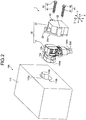
- Fig. 2 is an exploded perspective view illustrating the connector according to the embodiment.
- Fig. 3 is an exploded perspective view illustrating the connector according to the embodiment.
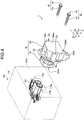
- Fig. 4 is a perspective view illustrating the connector according to the embodiment and a counterpart connector.
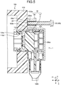
- Fig. 5 is a sectional view illustrating the connector according to the embodiment.
- Fig. 6 is a sectional view illustrating the connector according to the embodiment.
- Fig. 5 is a section taken along a line V-V illustrated in Fig. 1 .
- Fig. 6 is a sectional view corresponding to Fig. 5 .
- a connector 1 according to the embodiment is applied to, for example, a wire harness and the like used for a vehicle such as an automobile.
- the connector 1 according to the embodiment is physically and electrically connected to a counterpart connector 101 to be fitted.
- a direction in which the connector 1 is inserted into and removed from the counterpart connector 101 is referred to as a "front and rear direction X”
- a direction perpendicular to the front and rear direction X is referred to as a "width direction Y”
- a direction perpendicular to each of the front and rear direction X and the width direction Y is referred to as a "height direction Z".
- a side connected to the counterpart connector in the front and rear direction X is referred to as a "front side” and a side opposite to the front side is referred to as a "rear side”.
- a direction from the rear side to the front side is referred to as a “fitting direction” and a direction from the front side to the rear side is referred to as a "separation direction"
- the connector 1 is fixed to a fixed wall surface 100a of a counterpart device in a state of being connected to the counterpart connector 101 (see Fig. 4 ) provided in the counterpart device that is a connection target 100.
- the connection target 100 for example, is a device such as an inverter, which is mounted on a vehicle.
- the connector 1 includes a housing member 30 having a fitting part 10a and a fixed part 20sb.
- the fitting part 10a is fitted to the counterpart connector 101 and the fixed part 20sb is fixed to the fixed wall surface 100a.
- the housing member 30 of the present embodiment includes a connector housing 10 and a shield shell 20. That is, the connector 1 of the embodiment is a shield connector.
- the fitting part 10a is provided in the connector housing 10 and the fixed part 20sb is provided in the shield shell 20.
- the connector 1 is a female connector and the counterpart connector 101 is a male connector.
- the fitting part 10a of the present embodiment is formed as a female fitting part.
- the connector housing 10 is formed in a cylindrical shape to house a terminal TM and an electric wire EW therein.
- the connector housing 10 of the embodiment extends along the front and rear direction X and the end part of the rear side thereof in the front and rear direction X extends along the height direction Z, so that the connector housing 10 is formed in an approximately L-shaped cylindrical shape as a whole.
- the connector housing 10 of the embodiment houses the terminal TM and the electric wire EW therein and holds the terminal TM.
- the connector housing 10 is formed using a resin material, for example.
- the connector housing 10 has the fitting part 10a and an electric wire housing part 10b.
- the fitting part 10a is configured by a front portion of a part extending along the front and rear direction X.
- the electric wire housing part 10b is configured by both a rear portion of the part extending along the front and rear direction X and a part extending along the height direction Z.
- the fitting part 10a is a part formed by protruding from the electric wire housing part 10b, which extends in the height direction Z, to the front side in the front and rear direction X. Inner space parts of the fitting part 10a and the electric wire housing part 10b communicate with each other.
- the fitting part 10a is a part that is fitted to the counterpart connector 101 (see Fig. 4 ).
- the fitting part 10a of the embodiment is formed in an approximately long cylindrical shape that employs the width direction Y as a long side direction.
- the fitting part 10a houses and holds the terminal TM therein.
- the fitting part 10a has an exposed opening 10ha.
- the exposed opening 10ha is an opening that employs the front side in the front and rear direction X as an opening direction.
- the exposed opening 10ha is a terminal insertion hole through which the terminal TM in the fitting part 10a is exposed and into which a counterpart terminal 101a (see Fig. 4 ) of the counterpart connector 101 provided in the connection target 100 is inserted.
- the terminal TM is electrically connected to the counterpart terminal 101a inserted into the exposed opening 10ha when the fitting part 10a has been fitted to the counterpart connector 101 (see Fig. 4 ).
- the electric wire housing part 10b is a part into which the electric wire EW is inserted and which houses an end of the electric wire EW.
- the electric wire housing part 10b has an insertion opening 10hb.
- the insertion opening 10hb is an opening that employs a lower side in the height direction Z (lower side of the paper surface in Fig. 3 ) as an opening direction.
- the insertion opening 10hb is an electric wire insertion hole into which the electric wire EW is inserted.
- the end of the electric wire EW is housed in the electric wire housing part 10b via the insertion opening 10hb, so that the electric wire EW is electrically connected to the terminal TM in the fitting part 10a.
- Each part of the connector housing 10 including the fitting part 10a, the electric wire housing part 10b, and the like may be configured by combining a plurality of members such as a body member, a front holder, an inner housing, and a cover.
- the shield shell 20 suppresses the intrusion of external noise to the terminal TM and the electric wire EW housed in the connector housing 10.
- the shield shell 20 is formed of a conductive material such as a metal material.
- the shield shell 20 covers and shields a part of the connector housing 10. For example, as the conductive material of the shield shell 20, a conductive material that increases the strength of the shield shell 20 is used, as compared with the material of the connector housing 10.
- the shield shell 20 has a wall part 20sa and a fixed part 20sb, which are integrally formed with each other.
- the wall part 20sa is a part constituting a back plate facing the surface of a rear side of the electric wire housing part 10b in the front and rear direction X.
- the fixed part 20sb is a part that surrounds a part of the connector housing 10 with respect to a direction intersecting the front and rear direction X and is fixed to the fixed wall surface 100a.
- the fixed part 20sb is formed in a wall shape to protrude from an edge part of the wall part 20sa to the front side in the front and rear direction X.
- the fixed part 20sb is formed to surround the electric wire housing part 10b of the connector housing 10 from both sides in the width direction Y and an upper side in the height direction Z (upper side of Fig. 3 ).
- the fixed part 20sb includes a flange part 20a in which screw holes 21 (fixing screw holes), through holes 22 (fastening fixing through holes), a screw hole 23 (screw hole for separation work), and the like, which will be described below, are formed at an end part opposite to the wall part 20sa side in the front and rear direction X.
- the shield shell 20 is assembled to the connector housing 10 by fixing members 31.
- the fixing members 31 of the embodiment are fixing bolts.
- the connector housing 10 is formed with through holes 11 into which the fixing members 31 are inserted.
- the screw holes 21 (fixing screw holes) are formed in the flange part 20a of the fixed part 20sb of the shield shell 20 so as to communicate with the through holes 11 in the front and rear direction X.
- the screw holes 21 are opened on the front side in the flange part 20a and are closed on the rear side.
- the electric wire housing part 10b has a flange part 12 protruding in a flange shape in the width direction Y.
- the flange part 12 faces the flange part 20a of the fixed part 20sb in the front and rear direction X.
- the through holes 11 of the embodiment are formed in the flange part 12.
- the fixing members 31 are screwed into the screw holes 21 via the through holes 11, so that the shield shell 20 is attached to the connector housing 10.
- the connection target 100 of the embodiment includes a casing 110 and the counterpart connector 101 is provided in the casing 110.
- the casing 110 is formed in a rectangular box shape.
- a wall surface of the casing 110 serves as the fixed wall surface 100a.
- the fixed wall surface 100a is formed with an attachment hole 110a and fastening holes 110b.
- the attachment hole 110a allows an internal space of the casing 110 and an external space to communicate with each other.
- the fitting part 10a of the connector housing 10 is fitted to the counterpart connector 101 via the attachment hole 110a.
- the attachment hole 110a is formed in the casing 110 with a shape and a size that allow the fitting part 10a to be inserted.
- the attachment hole 110a of the embodiment is a hole having an approximately long elliptical shape when viewed from the front and rear direction X, and is formed as a hole slightly larger than the fitting part 10a.
- the fastening holes 110b are formed around the attachment hole 110a. In the embodiment, two fastening holes 110b are formed and are arranged along the width direction Y. The attachment hole 110a is located between the two fastening holes 110b.
- the fixed part 20sb of the embodiment has the through holes 22 (fastening fixing through holes) and the screw hole 23 (screw hole for separation work).
- the through holes 22 and the screw hole 23 are formed in the flange part 20a of the fixed part 20sb.
- the flange part 20a of the fixed part 20sb faces the fixed wall surface 100a along the front and rear direction X and abuts the fixed wall surface 100a in the state in which the connector 1 has been connected to the connection target 100.
- the through holes 22 penetrate the flange part 20a of the fixed part 20sb along the front and rear direction X.
- the through holes 22 are formed in a cylindrical shape.
- two through holes 22 of the embodiment are formed in the fixed part 20sb.
- the two through holes 22 are formed at positions of the fixed part 20sb, which face the fastening holes 110b, in the state in which the fitting part 10a has been fitted to the counterpart connector 101.
- the two through holes 22 communicate with the fastening holes 110b along the front and rear direction X (fitting direction), respectively, in the state in which the fitting part 10a has been fitted to the counterpart connector 101.
- each of the fastening bolts 40 has a shaft part 41 and a bolt head part 42.
- the shaft part 41 extends in a columnar shape.
- the shaft part 41 is formed on the surface thereof with a spiral screw groove (thread) along the extension direction thereof.
- the bolt head part 42 is a member that is provided at one end of the shaft part 41 and serves as a base part of the fastening bolt 40. That is, the bolt head part 42 is a pedestal part on which the shaft part 41 is vertically installed.
- the bolt head part 42 is formed as a part having a larger diameter than the shaft part 41.
- the fastening holes 110b is formed on the inner wall surface thereof with a screw groove (thread).
- the inner wall surface of the through hole 22 is formed with no screw groove and is formed as a smooth inner wall surface that is substantially even.
- the fastening bolts 40 are inserted into the through holes 22 along the fitting direction from the rear side of the housing member 30.
- the fastening bolts 40 inserted into the through holes 22 are screwed into the fastening holes 110b.
- the fastening bolts 40 are screwed into the fastening holes 110b, so that the fastening bolts 40 are fastened to the fastening holes 110b.
- the housing member 30 is fixed to the fixed wall surface 100a of the connection target 100.
- the fixed part 20sb is fixed to the fixed wall surface 100a together with the fitting part 10a in the state in which the fitting part 10a has been fitted to the counterpart connector 101.
- the shield shell 20 interposes the connector housing 10 between the fixed wall surface 100a and the shield shell 20 with respect to the front and rear direction X, so that the housing member 30 is fixed to the fixed wall surface 100a together with the connector housing 10.
- the screw hole 23 is a hole into which a separation member 50 (separation fastening member) used when the housing member 30 is separated from the fixed wall surface 100a is screwed.
- the screw hole 23 of the embodiment penetrates the flange part 20a of the fixed part 20sb along the front and rear direction X.
- a part of the fixed wall surface 100a facing the screw hole 23 in the front and rear direction X serves as a closed surface 100b that closes an opening on the front side of the screw hole 23.
- the screw hole 23 is formed in a portion of the flange part 20a, which is located on an upper side of the electric wire housing part 10b in the height direction Z.
- the screw hole 23 is formed on the inner wall surface thereof with a screw groove (thread).
- the fastening bolt 40 removed from the fastening hole 110b is used as the separation member 50. That is, in the present embodiment, the separation member 50 is also used as the fastening bolt 40.
- the screw hole 23 can be formed to be screwed with the fastening bolt 40 also used as the separation member 50. That is, the size of the screw hole 23, the shape of the screw groove, and the like are formed to correspond to the fastening bolt 40.
- the fastening bolts 40 are first removed from the fastening holes 110b and the through holes 22. Thereafter, in the connector 1, the removed fastening bolt 40 is used as the separation member 50 and is screwed into the screw hole 23 along the fitting direction from the rear side of the housing member 30. The fastening bolt 40 advances in the screw hole 23 along the fitting direction and abuts the closed surface 100b. Then, as illustrated in Fig. 6 , the fastening bolt 40 (separation member 50) is further screwed into the screw hole 23 to abut the closed surface 100b.
- the fastening bolt 40 is further screwed in the state of abutting the closed surface 100b, so that the housing member 30 is separated from the fixed wall surface 100a in the separation direction.
- the connector 1 is separated from the counterpart connector 101. That is, the connector 1 of the present embodiment is separated from the connection target 100 by axial force that acts on the fixed wall surface 100a from the fastening bolt 40 (separation member 50) screwed into the screw hole 23.
- the length of the screw hole 23 in the front and rear direction X is set in consideration of the strength of the fixed part 20sb, time required for screwing the separation member 50 to abut the fixed wall surface 100a as described above, and the like. For example, by shortening the length of the screw hole 23 in the front and rear direction X, it is possible to shorten the time until the fastening bolt 40 as the separation member 50 reaches the closed surface 100b. On the other hand, by increasing the length of the screw hole 23, it is possible to improve the strength of the fixed part 20sb at the time of separation work of the connector 1.
- the thickness of a part of the flange part 20a of the fixed part 20sb, in which the screw hole 23 is formed, in the front and rear direction X is formed to be thinner than that of a part of the fixed part 20sb, in which the through hole 22 is formed.
- the length of the screw hole 23 in the front and rear direction X is set to be shorter than that of the through hole 22 in the front and rear direction X.
- the screw groove may also be formed only in a part of the inner wall surface of the screw hole 23. With such a configuration, it is possible to shorten the time until the fastening bolt 40 reaches the closed surface 100b while holding the strength of the fixed part 20sb.
- the connector 1 includes the housing member 30 having the fitting part 10a that houses the terminal TM and is fitted to the counterpart connector 101 provided in the connection target 100 and the fixed part 20sb that is fixed to the fixed wall surface 100a of the connection target 100 together with the fitting part 10a in the state in which the fitting part 10a has been fitted to the counterpart connector 101, and the fixed part 20sb has the through holes 22, which communicate with the fastening holes 110b formed in the fixed wall surface 100a along the fitting direction between the fitting part 10a and the counterpart connector 101 and into which the fastening bolts 40 fastened to the fastening holes 110b are inserted along the fitting direction, in the state in which the fitting part 10a has been fitted to the counterpart connector 101, and the screw hole 23 into which the separation member 50 is screwed.
- the fixed part 20sb has the screw hole 23 into which the separation member 50 is screwed.
- separation force is applied to the fitting part 10a and the fixed part 20sb via the separation member 50 screwed into the screw hole 23.
- a load applied to the contact point by the spring may be designed to increase in order to reduce sliding wear between the terminals.
- fitting force between the connector and the counterpart connector increases and separation force required for separating the connector from the counterpart connector increases.
- separation force is applied via the separation member 50, the connector can be easily separated from the counterpart connector as compared with a case where the connector is directly separated from the counterpart connector by a human hand, for example.
- the screw hole 23 penetrates the fixed part 20sb along the fitting direction and faces the closed surface 100b of the fixed wall surface 100a along the fitting direction, and the separation member 50 is fitted into the screw hole 23 and abuts the closed surface 100b, so that the housing member 30 is separated from the fixed wall surface 100a in the separation direction along the fitting direction.
- the housing member 30 is separated from the fixed wall surface 100a in the separation direction by the axial force of the separation member 50 fitted into the screw hole 23 and abutting the closed surface 100b.
- the connector 1 uses the axial force of the separation member 50 as separation force for separating the housing member 30 from the counterpart connector, so that it is possible to apply large separation force as compared with a case where separation force is applied by a human hand, for example.
- the screw hole 23 can be screwed with the fastening bolt 40.
- the fastening bolt 40 used for fixing the housing member 30 to the fixed wall surface 100a can also be used as the separation member 50. That is, the fastening bolt 40 can also be used as the separation member 50.
- any dedicated member for separating the fitting part 10a from the counterpart connector 101 is not required. Consequently, it is possible to reduce the number of parts of the connector 1. Furthermore, it is possible to improve the versatility of the fastening bolt 40.
- the housing member 30 includes the connector housing 10 that is formed of a resin material and holds the terminal TM, and the shield shell 20 that is formed of a metal material and is assembled to the connector housing 10, the fitting part 10a is provided in the connector housing 10, and the fixed part 20sb is provided in the shield shell 20.
- the fixed part 20sb is provided in the shield shell 20 formed of a metal material, so that it is possible to ensure the strength of the fixed part 20sb.
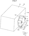
- Fig. 7 is a perspective view illustrating the connector according to the modification example of the embodiment.
- Fig. 8 is a perspective view illustrating the connector according to the modification example of the embodiment.
- Fig. 9 is a sectional view illustrating the connector according to the modification example of the embodiment.
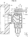
- Fig. 10 is a sectional view illustrating the connector according to the modification example of the embodiment.
- Fig. 9 is a sectional view corresponding to Fig. 5 .
- Fig. 10 is a sectional view corresponding to Fig. 6 .
- a connector 1 according to the modification example is different from the connector 1 according to the aforementioned embodiment in terms of the configuration of the screw hole 23.
- a part of the flange part 20a of the fixed part 20sb, in which the screw hole 23 is formed, in the front and rear direction X is formed with substantially the same thickness as that of a part of the fixed part 20sb, in which the through hole 22 is formed.
- the screw hole 23 is closed on the front side in the front and rear direction X and is opened on the rear side in the front and rear direction X. That is, a side of the screw hole 23 of the modification example, which faces the fixed wall surface 100a, is closed with respect to the fitting direction.
- the fastening bolt 40 separatation member 50
- a part on the bolt head part 42 side of the bolt head part 42 and the shaft part 41 is exposed from the screw hole 23.
- the bolt head part 42 is used as a hook part 50a of the separation member 50.
- the separation member 50 in the connector 1 according to the modification example, in the state in which the separation member 50 has been fitted into the screw hole 23, the separation member 50 has the hook part 50a at an end part that is located on a side opposite to the fixed wall surface 100a side in the fitting direction and exposed from the screw hole 23.
- the hook part 50a serves as a part for hooking a jig and the like for separating the housing member 30 from the connection target 100.
- the hook part 50a may also be used as a grip part that is gripped by a human hand and pulled along the separation direction.
- a side of the screw hole 23, which faces the fixed wall surface 100a, is closed with respect to the fitting direction, and in the state in which the separation member 50 has been fitted into the screw hole 23, the separation member 50 has the hook part 50a at an end part that is located on a side opposite to the fixed wall surface 100a side in the fitting direction and exposed from the screw hole 23.
- the hook part 50a can be used as a part for hooking a jig and the like for separating the housing member 30 from the connection target 100. Furthermore, the hook part 50a can also be used as a grip part that is gripped by a human hand and pulled along the separation direction. With such a configuration, the connector 1 according to the modification example has an effect that it is possible to easily separate the connectors from each other.
- a part of the fixed wall surface 100a, which faces the screw hole 23 in the front and rear direction X, may not be the closed surface 100b.
- the aforementioned modification example has been described using an example in which a side of the screw hole 23, which faces the fixed wall surface 100a, is closed with respect to the fitting direction.
- the screw hole 23 may also penetrate the fixed part 20sb in the fitting direction similarly to the aforementioned embodiment.
- the connectors 1 according to the aforementioned embodiment and modification example of the present invention are not limited to the aforementioned embodiment and modification example, and various modifications can be made within the scope of the claims.
- the configuration in which the screw hole 23 can be screwed with the fastening bolt 40 has been described as an example.
- the configuration of the screw hole 23 is not limited thereto.
- the screw hole 23 is not able to be screwed with the fastening bolt 40 and may have a shape in which a dedicated member used for separating the fitting part 10a from the counterpart connector 101 can be fitted.
- the configuration in which the housing member 30 includes the connector housing 10 and the shield shell 20 and the fixed part 20sb is provided in the shield shell 20 has been described as an example.
- the configuration of the housing member 30 is not limited thereto.
- the housing member 30 may also be formed as an integrated housing member formed of resin. That is, the fixed part 20sb may also be provided in the housing member formed of resin.
- a material for forming the connector housing 10 is not limited to the resin material.
- the housing member 30 may have a resinous mounting member instead of the metallic shield shell 20 and the mounting member may also be provided with a fixed part. In such a case, the through holes 22, the screw hole 23, and the like may also be configured by a metal collar and the like provided at the fixed part of the mounting member.
- the aforementioned embodiment and modification example have been described using an example in which the connector housing 10 viewed from the width direction Y has an L shape.
- the shape of the connector housing 10 is not limited thereto.
- the shape of the connector housing 10 may be a cylindrical shape extending along the front and rear direction X.
- the shield shell 20, for example is formed as a cylindrical member that covers the electric wire housing part 10b of the connector housing 10 from the outside.
- the fixed part has the screw hole into which the separation member is screwed.
- separation force is applied to the fitting part and the fixed part via the separation member screwed into the screw hole.
Landscapes
- Engineering & Computer Science (AREA)
- General Engineering & Computer Science (AREA)
- Mechanical Engineering (AREA)
- Details Of Connecting Devices For Male And Female Coupling (AREA)
- Connector Housings Or Holding Contact Members (AREA)
Applications Claiming Priority (1)
| Application Number | Priority Date | Filing Date | Title |
|---|---|---|---|
| JP2018238020A JP2020102307A (ja) | 2018-12-20 | 2018-12-20 | コネクタ |
Publications (2)
| Publication Number | Publication Date |
|---|---|
| EP3671974A1 true EP3671974A1 (de) | 2020-06-24 |
| EP3671974B1 EP3671974B1 (de) | 2022-06-08 |
Family
ID=68916367
Family Applications (1)
| Application Number | Title | Priority Date | Filing Date |
|---|---|---|---|
| EP19215971.3A Active EP3671974B1 (de) | 2018-12-20 | 2019-12-13 | Verbinder |
Country Status (4)
| Country | Link |
|---|---|
| US (1) | US11121501B2 (de) |
| EP (1) | EP3671974B1 (de) |
| JP (1) | JP2020102307A (de) |
| CN (1) | CN111509494B (de) |
Families Citing this family (5)
| Publication number | Priority date | Publication date | Assignee | Title |
|---|---|---|---|---|
| JP2020102307A (ja) * | 2018-12-20 | 2020-07-02 | 矢崎総業株式会社 | コネクタ |
| JP7055783B2 (ja) * | 2019-10-17 | 2022-04-18 | 矢崎総業株式会社 | 嵌合コネクタ |
| JP7803899B2 (ja) | 2023-06-26 | 2026-01-21 | 矢崎総業株式会社 | コネクタ |
| JP7810673B2 (ja) | 2023-06-29 | 2026-02-03 | 矢崎総業株式会社 | コネクタおよびワイヤハーネス |
| JP2025167156A (ja) * | 2024-04-25 | 2025-11-07 | 住友電装株式会社 | コネクタ及びコネクタアセンブリ |
Citations (2)
| Publication number | Priority date | Publication date | Assignee | Title |
|---|---|---|---|---|
| DE29502029U1 (de) * | 1995-02-08 | 1995-06-22 | Rheinbraun AG, 50935 Köln | Vorrichtung zum Trennen von elektrischen Kabelanschlüssen |
| JP2018041635A (ja) | 2016-09-08 | 2018-03-15 | 住友電装株式会社 | シールドコネクタ |
Family Cites Families (12)
| Publication number | Priority date | Publication date | Assignee | Title |
|---|---|---|---|---|
| JPH0537165A (ja) * | 1991-07-26 | 1993-02-12 | Matsushita Electric Ind Co Ltd | 電子機器筐体 |
| US6411526B1 (en) * | 2000-03-15 | 2002-06-25 | Tyco Electronics Power Systems, Inc. | Self-aligned, panel-mounted power cord set, method of manufacture therefor and an electronic equipment chassis employing the same |
| TWI223583B (en) * | 2003-09-16 | 2004-11-01 | Benq Corp | AD adapter module |
| TWI290390B (en) * | 2005-10-24 | 2007-11-21 | Benq Corp | The fixed seat of a socket |
| US20080117569A1 (en) * | 2006-11-20 | 2008-05-22 | Jia-Shunn Lee | Power-supplying device |
| JP4867977B2 (ja) * | 2008-11-12 | 2012-02-01 | ブラザー工業株式会社 | プラグ外し補助具 |
| US8152562B2 (en) * | 2009-04-02 | 2012-04-10 | Fci Americas Technology Llc | Cable panel mount |
| JP5733573B2 (ja) * | 2011-09-05 | 2015-06-10 | 住友電装株式会社 | 機器用コネクタ |
| JP2016162484A (ja) * | 2015-02-26 | 2016-09-05 | セイコーソリューションズ株式会社 | 接続プラグの取り外し具 |
| CN207069191U (zh) | 2017-07-04 | 2018-03-02 | 明峙睿 | 一种易拔的电源插头 |
| JP2020102307A (ja) * | 2018-12-20 | 2020-07-02 | 矢崎総業株式会社 | コネクタ |
| CN109688747B (zh) * | 2018-12-25 | 2020-10-16 | 苏州佳世达光电有限公司 | 电子装置 |
-
2018
- 2018-12-20 JP JP2018238020A patent/JP2020102307A/ja not_active Abandoned
-
2019
- 2019-12-13 EP EP19215971.3A patent/EP3671974B1/de active Active
- 2019-12-17 US US16/718,143 patent/US11121501B2/en active Active
- 2019-12-19 CN CN201911320422.6A patent/CN111509494B/zh active Active
Patent Citations (2)
| Publication number | Priority date | Publication date | Assignee | Title |
|---|---|---|---|---|
| DE29502029U1 (de) * | 1995-02-08 | 1995-06-22 | Rheinbraun AG, 50935 Köln | Vorrichtung zum Trennen von elektrischen Kabelanschlüssen |
| JP2018041635A (ja) | 2016-09-08 | 2018-03-15 | 住友電装株式会社 | シールドコネクタ |
Also Published As
| Publication number | Publication date |
|---|---|
| US20200203882A1 (en) | 2020-06-25 |
| JP2020102307A (ja) | 2020-07-02 |
| US11121501B2 (en) | 2021-09-14 |
| CN111509494B (zh) | 2022-07-26 |
| EP3671974B1 (de) | 2022-06-08 |
| CN111509494A (zh) | 2020-08-07 |
Similar Documents
| Publication | Publication Date | Title |
|---|---|---|
| EP3671974B1 (de) | Verbinder | |
| US10106109B2 (en) | Charging inlet connector assembled to a vehicle body of a vehicle mounted with a battery | |
| JP6434938B2 (ja) | コネクタ | |
| EP2456018A1 (de) | Wasserdichte struktur | |
| US20210091503A1 (en) | Connection terminal and terminal-equipped electric wire | |
| CN206789772U (zh) | 电缆的连接器结构 | |
| EP3783748B1 (de) | Verbinder | |
| CN103457064A (zh) | 连接器 | |
| JP2018174037A (ja) | シール部材および電気コネクタ | |
| CN206650178U (zh) | 电缆的连接器结构 | |
| US10446976B2 (en) | Shield connector and connector connection structure | |
| US12283775B2 (en) | Shield connector including shell having facing surface spaced away from engagement piece to regulate outward deformation of regulation piece | |
| JP6267892B2 (ja) | コネクタの一括シールド構造及び一括シールド方法 | |
| US10355400B2 (en) | Connector device | |
| US20240213703A1 (en) | Connector | |
| JP2010140873A (ja) | 機器用コネクタの防水構造 | |
| CN106463872B (zh) | 连接器 | |
| JP5840175B2 (ja) | コネクタ、及びコネクタユニット | |
| JPS5823177A (ja) | 速復型電気コネクタの遮蔽用カバ− | |
| CN116529964A (zh) | 连接器 | |
| US20240213721A1 (en) | Method for manufacturing shield shell and connector | |
| CN104577518A (zh) | 屏蔽构造 | |
| JP7732867B2 (ja) | 電気接続具及び電気接続箱 | |
| JPH07193966A (ja) | シールド端末処理構造 | |
| US20250266636A1 (en) | Connector and connector assembly |
Legal Events
| Date | Code | Title | Description |
|---|---|---|---|
| PUAI | Public reference made under article 153(3) epc to a published international application that has entered the european phase |
Free format text: ORIGINAL CODE: 0009012 |
|
| STAA | Information on the status of an ep patent application or granted ep patent |
Free format text: STATUS: REQUEST FOR EXAMINATION WAS MADE |
|
| 17P | Request for examination filed |
Effective date: 20191213 |
|
| AK | Designated contracting states |
Kind code of ref document: A1 Designated state(s): AL AT BE BG CH CY CZ DE DK EE ES FI FR GB GR HR HU IE IS IT LI LT LU LV MC MK MT NL NO PL PT RO RS SE SI SK SM TR |
|
| AX | Request for extension of the european patent |
Extension state: BA ME |
|
| RBV | Designated contracting states (corrected) |
Designated state(s): AL AT BE BG CH CY CZ DE DK EE ES FI FR GB GR HR HU IE IS IT LI LT LU LV MC MK MT NL NO PL PT RO RS SE SI SK SM TR |
|
| STAA | Information on the status of an ep patent application or granted ep patent |
Free format text: STATUS: EXAMINATION IS IN PROGRESS |
|
| 17Q | First examination report despatched |
Effective date: 20200820 |
|
| GRAP | Despatch of communication of intention to grant a patent |
Free format text: ORIGINAL CODE: EPIDOSNIGR1 |
|
| STAA | Information on the status of an ep patent application or granted ep patent |
Free format text: STATUS: GRANT OF PATENT IS INTENDED |
|
| GRAJ | Information related to disapproval of communication of intention to grant by the applicant or resumption of examination proceedings by the epo deleted |
Free format text: ORIGINAL CODE: EPIDOSDIGR1 |
|
| STAA | Information on the status of an ep patent application or granted ep patent |
Free format text: STATUS: EXAMINATION IS IN PROGRESS |
|
| INTG | Intention to grant announced |
Effective date: 20220221 |
|
| GRAP | Despatch of communication of intention to grant a patent |
Free format text: ORIGINAL CODE: EPIDOSNIGR1 |
|
| STAA | Information on the status of an ep patent application or granted ep patent |
Free format text: STATUS: GRANT OF PATENT IS INTENDED |
|
| INTC | Intention to grant announced (deleted) | ||
| GRAS | Grant fee paid |
Free format text: ORIGINAL CODE: EPIDOSNIGR3 |
|
| INTG | Intention to grant announced |
Effective date: 20220406 |
|
| GRAA | (expected) grant |
Free format text: ORIGINAL CODE: 0009210 |
|
| STAA | Information on the status of an ep patent application or granted ep patent |
Free format text: STATUS: THE PATENT HAS BEEN GRANTED |
|
| AK | Designated contracting states |
Kind code of ref document: B1 Designated state(s): AL AT BE BG CH CY CZ DE DK EE ES FI FR GB GR HR HU IE IS IT LI LT LU LV MC MK MT NL NO PL PT RO RS SE SI SK SM TR |
|
| REG | Reference to a national code |
Ref country code: AT Ref legal event code: REF Ref document number: 1497564 Country of ref document: AT Kind code of ref document: T Effective date: 20220615 Ref country code: CH Ref legal event code: EP |
|
| REG | Reference to a national code |
Ref country code: DE Ref legal event code: R096 Ref document number: 602019015645 Country of ref document: DE |
|
| REG | Reference to a national code |
Ref country code: IE Ref legal event code: FG4D |
|
| REG | Reference to a national code |
Ref country code: LT Ref legal event code: MG9D |
|
| REG | Reference to a national code |
Ref country code: NL Ref legal event code: MP Effective date: 20220608 |
|
| PG25 | Lapsed in a contracting state [announced via postgrant information from national office to epo] |
Ref country code: SE Free format text: LAPSE BECAUSE OF FAILURE TO SUBMIT A TRANSLATION OF THE DESCRIPTION OR TO PAY THE FEE WITHIN THE PRESCRIBED TIME-LIMIT Effective date: 20220608 Ref country code: NO Free format text: LAPSE BECAUSE OF FAILURE TO SUBMIT A TRANSLATION OF THE DESCRIPTION OR TO PAY THE FEE WITHIN THE PRESCRIBED TIME-LIMIT Effective date: 20220908 Ref country code: LT Free format text: LAPSE BECAUSE OF FAILURE TO SUBMIT A TRANSLATION OF THE DESCRIPTION OR TO PAY THE FEE WITHIN THE PRESCRIBED TIME-LIMIT Effective date: 20220608 Ref country code: HR Free format text: LAPSE BECAUSE OF FAILURE TO SUBMIT A TRANSLATION OF THE DESCRIPTION OR TO PAY THE FEE WITHIN THE PRESCRIBED TIME-LIMIT Effective date: 20220608 Ref country code: GR Free format text: LAPSE BECAUSE OF FAILURE TO SUBMIT A TRANSLATION OF THE DESCRIPTION OR TO PAY THE FEE WITHIN THE PRESCRIBED TIME-LIMIT Effective date: 20220909 Ref country code: FI Free format text: LAPSE BECAUSE OF FAILURE TO SUBMIT A TRANSLATION OF THE DESCRIPTION OR TO PAY THE FEE WITHIN THE PRESCRIBED TIME-LIMIT Effective date: 20220608 Ref country code: ES Free format text: LAPSE BECAUSE OF FAILURE TO SUBMIT A TRANSLATION OF THE DESCRIPTION OR TO PAY THE FEE WITHIN THE PRESCRIBED TIME-LIMIT Effective date: 20220608 Ref country code: BG Free format text: LAPSE BECAUSE OF FAILURE TO SUBMIT A TRANSLATION OF THE DESCRIPTION OR TO PAY THE FEE WITHIN THE PRESCRIBED TIME-LIMIT Effective date: 20220908 |
|
| REG | Reference to a national code |
Ref country code: AT Ref legal event code: MK05 Ref document number: 1497564 Country of ref document: AT Kind code of ref document: T Effective date: 20220608 |
|
| PG25 | Lapsed in a contracting state [announced via postgrant information from national office to epo] |
Ref country code: RS Free format text: LAPSE BECAUSE OF FAILURE TO SUBMIT A TRANSLATION OF THE DESCRIPTION OR TO PAY THE FEE WITHIN THE PRESCRIBED TIME-LIMIT Effective date: 20220608 Ref country code: LV Free format text: LAPSE BECAUSE OF FAILURE TO SUBMIT A TRANSLATION OF THE DESCRIPTION OR TO PAY THE FEE WITHIN THE PRESCRIBED TIME-LIMIT Effective date: 20220608 |
|
| PG25 | Lapsed in a contracting state [announced via postgrant information from national office to epo] |
Ref country code: NL Free format text: LAPSE BECAUSE OF FAILURE TO SUBMIT A TRANSLATION OF THE DESCRIPTION OR TO PAY THE FEE WITHIN THE PRESCRIBED TIME-LIMIT Effective date: 20220608 |
|
| PG25 | Lapsed in a contracting state [announced via postgrant information from national office to epo] |
Ref country code: SM Free format text: LAPSE BECAUSE OF FAILURE TO SUBMIT A TRANSLATION OF THE DESCRIPTION OR TO PAY THE FEE WITHIN THE PRESCRIBED TIME-LIMIT Effective date: 20220608 Ref country code: SK Free format text: LAPSE BECAUSE OF FAILURE TO SUBMIT A TRANSLATION OF THE DESCRIPTION OR TO PAY THE FEE WITHIN THE PRESCRIBED TIME-LIMIT Effective date: 20220608 Ref country code: RO Free format text: LAPSE BECAUSE OF FAILURE TO SUBMIT A TRANSLATION OF THE DESCRIPTION OR TO PAY THE FEE WITHIN THE PRESCRIBED TIME-LIMIT Effective date: 20220608 Ref country code: PT Free format text: LAPSE BECAUSE OF FAILURE TO SUBMIT A TRANSLATION OF THE DESCRIPTION OR TO PAY THE FEE WITHIN THE PRESCRIBED TIME-LIMIT Effective date: 20221010 Ref country code: EE Free format text: LAPSE BECAUSE OF FAILURE TO SUBMIT A TRANSLATION OF THE DESCRIPTION OR TO PAY THE FEE WITHIN THE PRESCRIBED TIME-LIMIT Effective date: 20220608 Ref country code: CZ Free format text: LAPSE BECAUSE OF FAILURE TO SUBMIT A TRANSLATION OF THE DESCRIPTION OR TO PAY THE FEE WITHIN THE PRESCRIBED TIME-LIMIT Effective date: 20220608 Ref country code: AT Free format text: LAPSE BECAUSE OF FAILURE TO SUBMIT A TRANSLATION OF THE DESCRIPTION OR TO PAY THE FEE WITHIN THE PRESCRIBED TIME-LIMIT Effective date: 20220608 |
|
| PG25 | Lapsed in a contracting state [announced via postgrant information from national office to epo] |
Ref country code: PL Free format text: LAPSE BECAUSE OF FAILURE TO SUBMIT A TRANSLATION OF THE DESCRIPTION OR TO PAY THE FEE WITHIN THE PRESCRIBED TIME-LIMIT Effective date: 20220608 Ref country code: IS Free format text: LAPSE BECAUSE OF FAILURE TO SUBMIT A TRANSLATION OF THE DESCRIPTION OR TO PAY THE FEE WITHIN THE PRESCRIBED TIME-LIMIT Effective date: 20221008 |
|
| REG | Reference to a national code |
Ref country code: DE Ref legal event code: R097 Ref document number: 602019015645 Country of ref document: DE |
|
| PG25 | Lapsed in a contracting state [announced via postgrant information from national office to epo] |
Ref country code: AL Free format text: LAPSE BECAUSE OF FAILURE TO SUBMIT A TRANSLATION OF THE DESCRIPTION OR TO PAY THE FEE WITHIN THE PRESCRIBED TIME-LIMIT Effective date: 20220608 |
|
| PLBE | No opposition filed within time limit |
Free format text: ORIGINAL CODE: 0009261 |
|
| STAA | Information on the status of an ep patent application or granted ep patent |
Free format text: STATUS: NO OPPOSITION FILED WITHIN TIME LIMIT |
|
| PG25 | Lapsed in a contracting state [announced via postgrant information from national office to epo] |
Ref country code: DK Free format text: LAPSE BECAUSE OF FAILURE TO SUBMIT A TRANSLATION OF THE DESCRIPTION OR TO PAY THE FEE WITHIN THE PRESCRIBED TIME-LIMIT Effective date: 20220608 |
|
| 26N | No opposition filed |
Effective date: 20230310 |
|
| PG25 | Lapsed in a contracting state [announced via postgrant information from national office to epo] |
Ref country code: SI Free format text: LAPSE BECAUSE OF FAILURE TO SUBMIT A TRANSLATION OF THE DESCRIPTION OR TO PAY THE FEE WITHIN THE PRESCRIBED TIME-LIMIT Effective date: 20220608 |
|
| REG | Reference to a national code |
Ref country code: CH Ref legal event code: PL |
|
| REG | Reference to a national code |
Ref country code: BE Ref legal event code: MM Effective date: 20221231 |
|
| PG25 | Lapsed in a contracting state [announced via postgrant information from national office to epo] |
Ref country code: LU Free format text: LAPSE BECAUSE OF NON-PAYMENT OF DUE FEES Effective date: 20221213 |
|
| PG25 | Lapsed in a contracting state [announced via postgrant information from national office to epo] |
Ref country code: LI Free format text: LAPSE BECAUSE OF NON-PAYMENT OF DUE FEES Effective date: 20221231 Ref country code: IE Free format text: LAPSE BECAUSE OF NON-PAYMENT OF DUE FEES Effective date: 20221213 Ref country code: CH Free format text: LAPSE BECAUSE OF NON-PAYMENT OF DUE FEES Effective date: 20221231 |
|
| PG25 | Lapsed in a contracting state [announced via postgrant information from national office to epo] |
Ref country code: FR Free format text: LAPSE BECAUSE OF NON-PAYMENT OF DUE FEES Effective date: 20221231 Ref country code: BE Free format text: LAPSE BECAUSE OF NON-PAYMENT OF DUE FEES Effective date: 20221231 |
|
| PG25 | Lapsed in a contracting state [announced via postgrant information from national office to epo] |
Ref country code: IT Free format text: LAPSE BECAUSE OF FAILURE TO SUBMIT A TRANSLATION OF THE DESCRIPTION OR TO PAY THE FEE WITHIN THE PRESCRIBED TIME-LIMIT Effective date: 20220608 |
|
| PG25 | Lapsed in a contracting state [announced via postgrant information from national office to epo] |
Ref country code: HU Free format text: LAPSE BECAUSE OF FAILURE TO SUBMIT A TRANSLATION OF THE DESCRIPTION OR TO PAY THE FEE WITHIN THE PRESCRIBED TIME-LIMIT; INVALID AB INITIO Effective date: 20191213 |
|
| PG25 | Lapsed in a contracting state [announced via postgrant information from national office to epo] |
Ref country code: CY Free format text: LAPSE BECAUSE OF FAILURE TO SUBMIT A TRANSLATION OF THE DESCRIPTION OR TO PAY THE FEE WITHIN THE PRESCRIBED TIME-LIMIT Effective date: 20220608 |
|
| PG25 | Lapsed in a contracting state [announced via postgrant information from national office to epo] |
Ref country code: MK Free format text: LAPSE BECAUSE OF FAILURE TO SUBMIT A TRANSLATION OF THE DESCRIPTION OR TO PAY THE FEE WITHIN THE PRESCRIBED TIME-LIMIT Effective date: 20220608 |
|
| PG25 | Lapsed in a contracting state [announced via postgrant information from national office to epo] |
Ref country code: MC Free format text: LAPSE BECAUSE OF FAILURE TO SUBMIT A TRANSLATION OF THE DESCRIPTION OR TO PAY THE FEE WITHIN THE PRESCRIBED TIME-LIMIT Effective date: 20220608 |
|
| PG25 | Lapsed in a contracting state [announced via postgrant information from national office to epo] |
Ref country code: TR Free format text: LAPSE BECAUSE OF FAILURE TO SUBMIT A TRANSLATION OF THE DESCRIPTION OR TO PAY THE FEE WITHIN THE PRESCRIBED TIME-LIMIT Effective date: 20220608 Ref country code: MC Free format text: LAPSE BECAUSE OF FAILURE TO SUBMIT A TRANSLATION OF THE DESCRIPTION OR TO PAY THE FEE WITHIN THE PRESCRIBED TIME-LIMIT Effective date: 20220608 |
|
| GBPC | Gb: european patent ceased through non-payment of renewal fee |
Effective date: 20231213 |
|
| PG25 | Lapsed in a contracting state [announced via postgrant information from national office to epo] |
Ref country code: MT Free format text: LAPSE BECAUSE OF FAILURE TO SUBMIT A TRANSLATION OF THE DESCRIPTION OR TO PAY THE FEE WITHIN THE PRESCRIBED TIME-LIMIT Effective date: 20220608 |
|
| PG25 | Lapsed in a contracting state [announced via postgrant information from national office to epo] |
Ref country code: GB Free format text: LAPSE BECAUSE OF NON-PAYMENT OF DUE FEES Effective date: 20231213 |
|
| PG25 | Lapsed in a contracting state [announced via postgrant information from national office to epo] |
Ref country code: GB Free format text: LAPSE BECAUSE OF NON-PAYMENT OF DUE FEES Effective date: 20231213 |
|
| PG25 | Lapsed in a contracting state [announced via postgrant information from national office to epo] |
Ref country code: BG Free format text: LAPSE BECAUSE OF FAILURE TO SUBMIT A TRANSLATION OF THE DESCRIPTION OR TO PAY THE FEE WITHIN THE PRESCRIBED TIME-LIMIT Effective date: 20220608 |
|
| PG25 | Lapsed in a contracting state [announced via postgrant information from national office to epo] |
Ref country code: BG Free format text: LAPSE BECAUSE OF FAILURE TO SUBMIT A TRANSLATION OF THE DESCRIPTION OR TO PAY THE FEE WITHIN THE PRESCRIBED TIME-LIMIT Effective date: 20220608 |
|
| PGFP | Annual fee paid to national office [announced via postgrant information from national office to epo] |
Ref country code: DE Payment date: 20251028 Year of fee payment: 7 |