EP3671979A1 - Reiseadapter sowie set umfassend einen reiseadapter - Google Patents
Reiseadapter sowie set umfassend einen reiseadapter Download PDFInfo
- Publication number
- EP3671979A1 EP3671979A1 EP18215236.3A EP18215236A EP3671979A1 EP 3671979 A1 EP3671979 A1 EP 3671979A1 EP 18215236 A EP18215236 A EP 18215236A EP 3671979 A1 EP3671979 A1 EP 3671979A1
- Authority
- EP
- European Patent Office
- Prior art keywords
- socket
- contact
- housing
- contact pin
- plug
- Prior art date
- Legal status (The legal status is an assumption and is not a legal conclusion. Google has not performed a legal analysis and makes no representation as to the accuracy of the status listed.)
- Granted
Links
Images


Classifications
-
- H—ELECTRICITY
- H01—ELECTRIC ELEMENTS
- H01R—ELECTRICALLY-CONDUCTIVE CONNECTIONS; STRUCTURAL ASSOCIATIONS OF A PLURALITY OF MUTUALLY-INSULATED ELECTRICAL CONNECTING ELEMENTS; COUPLING DEVICES; CURRENT COLLECTORS
- H01R31/00—Coupling parts supported only by co-operation with counterpart
- H01R31/06—Intermediate parts for linking two coupling parts, e.g. adapter
-
- H—ELECTRICITY
- H01—ELECTRIC ELEMENTS
- H01R—ELECTRICALLY-CONDUCTIVE CONNECTIONS; STRUCTURAL ASSOCIATIONS OF A PLURALITY OF MUTUALLY-INSULATED ELECTRICAL CONNECTING ELEMENTS; COUPLING DEVICES; CURRENT COLLECTORS
- H01R27/00—Coupling parts adapted for co-operation with two or more dissimilar counterparts
-
- H—ELECTRICITY
- H01—ELECTRIC ELEMENTS
- H01R—ELECTRICALLY-CONDUCTIVE CONNECTIONS; STRUCTURAL ASSOCIATIONS OF A PLURALITY OF MUTUALLY-INSULATED ELECTRICAL CONNECTING ELEMENTS; COUPLING DEVICES; CURRENT COLLECTORS
- H01R13/00—Details of coupling devices of the kinds covered by groups H01R12/70 or H01R24/00 - H01R33/00
- H01R13/44—Means for preventing access to live contacts
- H01R13/447—Shutter or cover plate
-
- H—ELECTRICITY
- H01—ELECTRIC ELEMENTS
- H01R—ELECTRICALLY-CONDUCTIVE CONNECTIONS; STRUCTURAL ASSOCIATIONS OF A PLURALITY OF MUTUALLY-INSULATED ELECTRICAL CONNECTING ELEMENTS; COUPLING DEVICES; CURRENT COLLECTORS
- H01R31/00—Coupling parts supported only by co-operation with counterpart
- H01R31/06—Intermediate parts for linking two coupling parts, e.g. adapter
- H01R31/065—Intermediate parts for linking two coupling parts, e.g. adapter with built-in electric apparatus
-
- H—ELECTRICITY
- H01—ELECTRIC ELEMENTS
- H01R—ELECTRICALLY-CONDUCTIVE CONNECTIONS; STRUCTURAL ASSOCIATIONS OF A PLURALITY OF MUTUALLY-INSULATED ELECTRICAL CONNECTING ELEMENTS; COUPLING DEVICES; CURRENT COLLECTORS
- H01R35/00—Flexible or turnable line connectors, i.e. the rotation angle being limited
- H01R35/04—Turnable line connectors with limited rotation angle with frictional contact members
-
- H—ELECTRICITY
- H01—ELECTRIC ELEMENTS
- H01R—ELECTRICALLY-CONDUCTIVE CONNECTIONS; STRUCTURAL ASSOCIATIONS OF A PLURALITY OF MUTUALLY-INSULATED ELECTRICAL CONNECTING ELEMENTS; COUPLING DEVICES; CURRENT COLLECTORS
- H01R13/00—Details of coupling devices of the kinds covered by groups H01R12/70 or H01R24/00 - H01R33/00
- H01R13/66—Structural association with built-in electrical component
- H01R13/68—Structural association with built-in electrical component with built-in fuse
- H01R13/684—Structural association with built-in electrical component with built-in fuse the fuse being removable
- H01R13/688—Structural association with built-in electrical component with built-in fuse the fuse being removable with housing part adapted for accessing the fuse
-
- H—ELECTRICITY
- H01—ELECTRIC ELEMENTS
- H01R—ELECTRICALLY-CONDUCTIVE CONNECTIONS; STRUCTURAL ASSOCIATIONS OF A PLURALITY OF MUTUALLY-INSULATED ELECTRICAL CONNECTING ELEMENTS; COUPLING DEVICES; CURRENT COLLECTORS
- H01R24/00—Two-part coupling devices, or either of their cooperating parts, characterised by their overall structure
- H01R24/66—Two-part coupling devices, or either of their cooperating parts, characterised by their overall structure with pins, blades or analogous contacts and secured to apparatus or structure, e.g. to a wall
- H01R24/70—Two-part coupling devices, or either of their cooperating parts, characterised by their overall structure with pins, blades or analogous contacts and secured to apparatus or structure, e.g. to a wall with additional earth or shield contacts
Definitions
- the invention relates to travel adapters and a set comprising the travel adapter.
- Electrical adapters in particular so-called travel adapters, are known per se. They consist of at least one plug and at least one socket.
- the plug has a contact device which is adapted or adaptable to country-specific standards (in short: standards) of the socket.
- the socket has at least two contact openings which are shaped and spaced apart such that a contact device of a power plug z.
- electrical device for example the contact device of the power plug type C (CEE 7/16), can be connected to this.
- the EP 1 257 018 B1 discloses an electrical plug adapter for the optional connection of a plug system as a plug to different country-specific plug systems.
- the plug adapter has a housing, on the outer circumference of which there are arranged several different projecting plug systems and has a socket pot as a socket, which is rotatably mounted in the housing.
- the socket pot has electrical contacts which can be connected in the rotational positions of the socket pot associated with the outer plug systems with corresponding electrical contacts of the respective plug systems, one of the plug systems having a protective contact pin movably mounted in the housing.
- the D 199 02 642 A1 discloses a multiple travel connector with a housing, on the side flanks of which plugs are provided in accordance with different country standards, and with a socket rotatably arranged on the housing with respect to the housing as a socket, which is electrically and mechanically connected to a pair of contacts.
- the contact pair resiliently rests against one of several pairs of contact surfaces. The pairs of contact surfaces are connected to the contact pins of each connector.
- a travel adapter is to be created which can be used in countries with different standards and whose handling is improved for the user in the respective countries.
- a set comprising the travel adapter is to be created which is easy to use in many countries and whose handling is improved.
- a travel adapter comprises a housing, at least one socket of a first standard and at least one plug of a second standard.
- the socket of the first standard has at least a first contact socket and a second contact socket and the plug of the second standard has at least a first contact pin and a second contact pin.
- the plug is arranged on the housing and the socket is rotatably mounted in the housing.
- the socket has a socket housing, contact elements being arranged in the socket housing, each of which is connected to the first contact socket and the second contact socket of the socket.
- the contact elements can be electrically connected to the first contact pin or the second contact pin of the respective plug by rotating the socket relative to the housing into an operating position corresponding to the respective plug.
- the plug or the first contact pin and the second contact pin are arranged pivotably on the housing such that the plug or the first contact pin and the second contact pin can be pivoted out of the housing.
- the user can move only the plug suitable there, or only the first contact pin and second contact pin suitable there, into the operating position. There is only one operating position for the plug or for the first contact pin and the second contact pin. This ensures that the travel adapter can be used correctly and without any doubt in the desired country.
- This travel adapter protects the user from having to try out different plugs in the respective country. This improves handling on the one hand and ensures a high level of safety in use on the other.
- the operating position is the pivoted-out end position in which the plug or the first contact pin and the second contact pin can be plugged into an external or separate socket.
- a rest position is that end position swung in, in which the plug or the first contact pin and the second contact pin are pivoted at least in sections in the housing.
- the plug or the first contact pin and the second contact pin are arranged such that they can be pivoted out of the rest position on the housing.
- the plug or the first contact pin and the second contact pin can be arranged essentially freely on the housing, so that their functional use is essentially comparable to the arrangement of the plug or the first contact pin and the second contact pin in the housing.
- the arrangement in the housing prevents the plug or the first contact pin and the second contact pin from getting caught with other objects, for example with objects such as luggage, which is located directly in the vicinity of the travel adapter
- the respective contact elements are preferably formed in one piece with the respective contact sockets. This can prevent the contact elements from detaching from one another in the housing, which can improve the functional stability of the travel adapter.
- the first contact pin and the second contact pin are preferably coupled to one another in such a way that they can be pivoted out of the housing together.
- the first contact pin and the second contact pin can thus be moved synchronously from their rest position into their operating position. They thus reach their operating position at the same time, so that the user can simply plug them into an external or separate socket.
- the socket has a contact tongue for establishing a protective conductor connection and the plug has a third contact pin as a protective conductor pin, a third contact element being arranged in the socket housing and being connected to the contact tongue, and the first contact pin and the second contact pin and the third contact pin are coupled to one another such that they can be pivoted out of the housing together.
- the contact tongue can be connected to the third contact pin using the third contact element.
- the third is Contact element arranged on the socket housing and thus rotatably mounted in the housing of the travel adapter. The coupling of the contact pins enables a synchronous movement of all three contact pins, so that they can easily be moved into their respective operating positions.
- the third contact pin can preferably be moved linearly.
- the third contact pin can be designed as a protective conductor pin, which can be located between the first contact pin and the second contact pin.
- the protective conductor pin can be movable normally to the connecting straight line which extends between the first contact pin and the second contact pin.
- a plug with a linearly movable protective conductor pin has an elongated hole in which the protective conductor pin can move linearly.
- a linear movement is a movement along the longitudinal extension of the elongated hole.
- the Swiss plug standard, the Italian plug standard and the Brazilian plug standard can be covered with one and the same plug.
- the socket has a third contact socket for establishing a protective conductor connection.
- the third contact socket can also be connected to the third contact pin using the third contact element.
- a travel adapter with three contact sockets has a simple structure that keeps an external or separate plug stable after it is plugged into the socket.
- the first contact pin and the second contact pin can preferably be pivoted out in a first pivoting direction and the third contact pin can be pivoted out in a second pivoting direction that is opposite to the first pivoting direction. This allows the contact pins to be placed in the rest position in the housing of the travel adapter to save space.
- the third contact pin is designed as the protective conductor pin, so that it can be pivoted in the opposite direction to the first and to the second contact pin.
- the third contact pin can be both linearly and pivotally movable. This makes the third contact pin, which is designed as a protective conductor pin, particularly flexible to use.
- a gear is preferably provided for coupling.
- a gear mechanism for the contact pins which can be swung out together brings about a synchronous movement of these contact pins when swiveling them out into their operating position.
- a gear transmission is provided for coupling the contact pins.
- a gear transmission has toothing which enables efficient coupling of the contact pins which can be swung out together, the gear transmission having a compact structure.
- the contact pins can be moved precisely from their rest positions into their operating positions and back again using the toothing.
- a coupling rod gear is provided as a coupling of the contact pins.
- a coupling rod gear enables a particularly reliable coupling of the contact pins to be moved together. This means that the contact pins are hardly stressed mechanically, which can extend the life of the travel adapter.
- a gear notch is provided on the gear for receiving at least one of the contact pins.
- the travel adapter preferably has an unlocking mechanism which enables the respective plug or the first contact pin and the second contact pin to be pivoted out when the socket is in the respective operating position.
- the unlocking mechanism can prevent the remaining plugs or first contact pins and second contact pins from swinging out, so that they remain in their rest position. After the desired standard has been selected, the user can now only use the appropriate plug or first contact pin and second contact pin.
- the unlocking mechanism is preferably formed at least in two parts and has an unlocking link and an engagement element.
- the unlocking link and the engaging element cooperate in such a way that reliable unlocking is possible and jamming of the plugs and / or the contact pins can be prevented. It is advantageous Unlocking mechanism formed in two parts, so that it has a simple construction.
- the unlocking link is preferably on the socket housing and the engaging element is arranged on the plug.
- the arrangement of the unlocking link on the socket housing enables stable actuation of the unlocking mechanism when the socket is turned.
- the engagement element can be arranged on the plug or on the first contact pin and / or second contact pin, but also on the coupling or on the gear, so that the engagement element can be arranged close to the socket housing and thus a reliable and stable interaction of the unlocking link and the engaging element is possible.
- the travel adapter preferably has a receptacle for overcurrent protection.
- Travel adapters are used in different countries with different energy networks. Overcurrent protection is an advantage for the safe use of the travel adapter and may be necessary with regard to country-specific certification regulations. If a damaged device is connected to the travel adapter, the overcurrent fuse prevents damage to the travel adapter, since the overcurrent fuse is triggered. The holder ensures easy replacement of the overcurrent fuse.
- the receptacle is arranged on the can housing.
- the receptacle and thus the overcurrent fuse arranged therein can thus be arranged close to the contact sockets.
- the receptacle of the socket is preferably arranged opposite one another. This allows the size of the travel adapter to be kept small.
- the overcurrent fuse is a fuse. Fuses can be manufactured for different overcurrent protection classes and have a compact design and a low weight.
- the receptacle in the position led out of the can housing is advantageously not separable from the can housing. This means that the recording cannot be lost. At the same time, it can thus be ensured that the contact sockets or the contact elements in the socket housing cannot be touched.
- the travel adapter preferably has a locking device for locking the receptacle.
- the locking device prevents access to the overcurrent protection when one of the plugs or contact pins is in its operating position. This further improves the safe use of the travel adapter.
- the locking device is preferably formed at least in two parts and has a locking cam and a locking groove.
- the locking cams and the locking groove engage firmly and prevent the holder from opening.
- the locking groove is preferably arranged on the housing and the locking cam is arranged on the receptacle. This enables a stable interaction of these elements of the locking device on the travel adapter.
- the locking groove and the locking cam can be brought into an operative connection in a position of the socket housing, so that the receptacle can be detached from the socket housing.
- This position is different for each operating position of the connector or contact pin. This can ensure that the overcurrent fuse can only be removed when all the plugs or contact pins are in their rest position and the travel adapter is therefore not in electrical contact with an external energy network.
- the travel adapter preferably has an interface which makes it possible to arrange an additional module on the travel adapter and to electrically connect this additional module to the socket.
- An electrical device can thus also be connected to the travel adapter, so that the range of use of the travel adapter described here is further improved.
- the interface advantageously has an electrical contact which interacts with an electrical contact on the additional module, so that the additional module can be supplied with electrical energy.
- the additional module from the group of a USB charger module, mobile battery module, Bluetooth® module, WiFi module, wireless charger module, IoT (Internet of Things) module, night light module, Storage compartment module for a cable, smartphone holder module, smart meter module (in particular with a voltage, current and power display), key finder module, smoke detector module, mosquito repellent module or room fragrance module .
- an electrical device such as a smartphone, tablet or a music player
- the USB charger module so that the battery arranged therein can be charged.
- the travel adapter preferably has at least one recessed grip for rotating the socket.
- the at least one recessed grip makes it easier for the user of the travel adapter to handle the travel adapter. The user can hold the travel adapter with one hand and turn the socket of the travel adapter into the desired position with the other hand.
- This recessed grip is preferably arranged on the can housing. This improves the haptics for the user of the travel adapter and thus simplifies the turning of the socket.
- this recessed grip is arranged at the interface.
- the recessed grip and the interface are thus arranged on the same component of the housing, as a result of which the recessed grip and the interface can be produced in one work step. If necessary, the socket can be turned using an additional module located at the interface.
- the travel adapter preferably has two recessed handles for rotating the socket.
- the user can, for example, engage one of the recessed grips with one finger and twist the socket.
- the two recessed grips allow a secure hold when turning the socket.
- the two recessed grips are advantageously arranged at opposite positions, which enables easy handling.
- the socket in the socket housing is preferably compatible with plugs of the Brazilian, Italian and Swiss standards.
- the socket in the socket housing can also be compatible with type J, type L or type N plugs, which increases the flexibility of the travel adapter.
- At least one operating trough is preferably provided on the travel adapter for pivoting out the plug. After the user of the travel adapter has selected the plug of the desired standard and has turned the socket into the intended position, the user can reach into the operating recess and swivel the selected plug out of the housing simply and largely without resistance.
- At least one actuation trough is provided on the travel adapter for pivoting out the first contact pins and the second contact pins.
- the user can use the actuation trough to simply swing the first contact pin and the second contact pin out of the housing, which improves handling for the user. Furthermore, it can be ensured with the help of the actuating trough that all contact pins can be pivoted out of the housing.
- a snap-in cam for interacting with the housing is preferably arranged on the plug such that the plug can be locked in a rest position in the housing and in a pivoted-out operating position. This prevents the plug from either leaving the rest position or the swung-out operating position unintentionally, which improves the operational safety of the travel adapter.
- a snap-in cam for interacting with the housing is arranged on the first contact pins and the second contact pins, such that the first contact pin and the second contact pin can be locked in a rest position in the housing and in a pivoted-out operating position. This prevents the contact pins from either leaving the rest position or the swung-out operating position unintentionally, which improves the operational safety of the travel adapter.
- At least one widening element is preferably arranged on the housing.
- the at least one distribution element enables the socket housing to rest firmly against an external socket if the travel adapter is arranged in the external socket with a plug or a first contact pin and a second contact pin.
- the housing of the plug preferably has at least one widening element.
- the widening element enables a space-saving arrangement of the relatively wide contact pins from the British standard in the housing of the travel adapter.
- a standard for travel adapters for example the British standard, may stipulate a minimum footprint for the housing side of the travel adapter on which the plug or the contact pins are arranged.
- this standard or another standard may require that the swiveled-out contact pins unite have a predetermined distance from at least one edge region of the housing side.
- the travel adapter described here advantageously has at least one widening element.
- the at least one widening element can be moved into an activation position by means of a link guide by pivoting the plug out.
- the link guide enables stable movement of the at least one widening element in its activation position, as a result of which repeated movement of the at least one widening element can be carried out without wear.
- the at least one widening element can be moved into an activation position by means of a link guide by pivoting out the first contact pin and the second contact pin. This saves an additional drive mechanism for the movement of the distribution elements, making the travel adapter lightweight and compact.
- the widening elements are moved out of the housing to such an extent that the resulting base area on the housing side meets the requirements of the relevant standard.
- the widening elements are arranged in the housing so that the travel adapter remains as compact as possible.
- the properties that are advantageous for the user of the travel adapter, such as light, small and compact design, can thus be sufficiently fulfilled.
- At least one further widening element is arranged on the housing and can be moved into an activation position by means of a link guide by pivoting out the first contact pin and the second contact pin.
- the at least one further distribution element enables the socket housing to rest even more stably on an external socket.
- Another travel adapter comprises a housing, at least one socket of a first standard and at least one plug of a second standard, the socket of the first standard having at least a first contact socket and a second contact socket and the plug of the second standard having at least a first contact pin and a second Has contact pin.
- the first contact pin is with the first contact socket is electrically connected and the second contact pin is electrically connected to the second contact socket.
- the first contact pin and the second contact pin are movably arranged on the housing.
- At least one widening element is arranged on the housing, said element being movable in an activation position.
- the at least one activated distribution element enables a standard-compliant base area and a stable contact of the housing of the travel adapter with an external socket (mains socket) if the first contact pin and the second contact pin are arranged in the contact sockets of an external socket.
- the at least one widening element enables a compact construction of the travel adapter, as a result of which the size of the travel adapter can be further reduced.
- the activation position of the at least one spreading element can be reached when the first contact pin and the second contact pin are in their operating position.
- the widening elements can be in an inactive position when the first contact pin and the second contact pin are in their rest position. In the inactive position, the widening elements are arranged in sections in the housing and form a space-saving, compact unit with the housing sides.
- the operating position of the first contact pin and the second contact pin is that end position moved out in which the first contact pin and the second contact pin can be plugged into an external or separate socket.
- a rest position is that end position moved into which the first contact pin and the second contact pin are located at least in sections in the housing.
- the at least one widening element is preferably arranged on the housing in such a way that it can be moved into an activation position by moving out the first contact pin and the second contact pin.
- the travel adapter can have a triggering device for activating the at least one widening element.
- the user can activate the triggering device, for example via a trigger button, which releases the at least one widening element, so that it is moved from its inactive position to its activation position.
- the Trigger device have a gear, which can be arranged in the housing of the travel adapter and which connects the trigger button with the contact pins, so that the contact pins can be moved out of the housing with the aid of the gear.
- the release button can be arranged on the housing of the travel adapter so that it is easily accessible to the user.
- the plug preferably has a further widening element, which can be moved into an activation position by moving the first contact pin and the second contact pin out.
- the widening elements are moved out of the housing to such an extent that the resulting base area on the housing side meets the requirements of the relevant standard.
- the widening elements are arranged in the housing so that the travel adapter remains as compact as possible.
- the plug is designed in accordance with the British standard, the first contact pin and the second contact pin being wider and, according to the standard, positioned comparatively broadly to one another than in other standards.
- These wide contact pins and their spacing from one another require comparatively more space in the housing of a travel adapter.
- the widening elements described here are particularly suitable for making the travel adapter particularly compact.
- the at least one and the further widening element can each be moved by means of a link guide.
- the link guides enable these widening elements to be moved stably in their activation position, as a result of which these widening elements can be moved several times without wear. This saves an additional drive mechanism for the movement of the distribution elements, making the travel adapter lightweight and compact.
- the first contact pin and the second contact pin are preferably coupled to one another in such a way that they can be moved out of the housing together.
- the first contact pin and the second contact pin can thus be moved synchronously from their rest position into their operating position. They thus reach their operating position at the same time, so that the user can simply plug them into an external or separate socket.
- At least the first contact pin and the second contact pin can advantageously be moved linearly out of the housing.
- the two contact pins can be moved out of the housing using contact pin guides.
- At least the first contact pin and the second contact pin can advantageously be pivoted out of the housing. This makes it particularly easy to move these contact pins out of the housing and also to move them back in again.
- the first contact pin and the second contact pin are preferably coupled to one another in such a way that they can be moved out of the housing together.
- the first contact pin and the second contact pin can thus be moved synchronously from their rest position into their operating position. They thus reach their operating position at the same time, so that the user can simply plug them into an external or separate socket.
- the socket preferably has a third contact socket which is connected to a third contact pin which can be moved out of the housing and which is a protective conductor pin.
- first contact pin and the second contact pin and the third contact pin are coupled to one another such that they can be moved out of the housing together.
- the coupling of the contact pins enables a synchronous movement of all three contact pins, so that they can easily be moved into their respective operating positions.
- the first contact pin and the second contact pin can preferably be pivoted out in a first pivoting direction and the third contact pin can be pivoted out in a second pivoting direction that is opposite to the first pivoting direction. This allows the contact pins to be placed in the rest position in the housing of the travel adapter to save space.
- the third contact pin is designed as the protective conductor pin, so that it can be pivoted in the opposite direction to the first and to the second contact pin.
- the third contact socket preferably has an elongated hole. This means that one and the same socket can meet the Swiss plug standard, the Italian plug standard and the Brazilian plug standard.
- the travel adapter preferably has an interface which makes it possible to arrange an additional module as described here on the travel adapter and to electrically connect the additional module arranged at the interface to the socket.
- An electrical device can thus also be connected to the travel adapter, so that the range of use of the travel adapter described here is further improved.
- the interface advantageously has an electrical contact which interacts with an electrical contact on the additional module, so that the additional module can be supplied with electrical energy.
- a set according to the invention comprises one of the travel adapters described here and a plug adapter.
- the plug adapter has a plug adapter housing, on which a plug for interacting with the socket of the travel adapter is arranged, as well as one or more sockets of different standards.
- the plug-in adapter can have an essentially disk-shaped plug-in adapter housing, so that the set can be of compact construction in the assembled state.
- the plug of the plug adapter has a first standard, so that it can advantageously be plugged into the socket of the travel adapter.
- the plug of the plug adapter is thus electrically connected to the contact sockets of the socket, and thus an electrical device of a first standard connected to the socket of the plug adapter can be electrically connected to an external socket of a second standard.
- the socket of the plug adapter advantageously comprises several standards, so that devices with plugs of different standards can be connected to this socket. This further improves the flexibility of the travel adapter or set.
- the set preferably comprises one of the travel adapters as described here and an additional module for interacting with the interface of the travel adapter. This can further improve the flexibility of the set, as previously described.
- the travel adapter 100 comprises a housing 101 in which a socket 10 is arranged and in which several plugs 20, 20 ', 20 ", 20"' of different standards are arranged.
- the socket 10 is designed to accommodate external plugs of different standards.
- the socket 10 has a socket housing 15 in which a first contact socket 11, a second contact socket 12 and a third contact socket 13 are arranged.
- the contact sockets 11, 12, 13 are designed to receive contact pins from external plugs (mains plugs) of different standards and to interact with them.
- In the socket housing 15 there are also contact tongues 14, 14 ', which can also interact with contacts of an external plug and are electrically connected to the contact socket 13.
- the socket 10 is rotatably mounted in the direction of rotation R in the housing 101 and the plugs 20, 20 ', 20 “, 20”' are arranged on the respective housing sides 105, 106, 107, 108 of the housing 101, in each case offset by 90 ° to one another and pivotally arranged on the housing 101.
- the respective plug 20, 20 ', 20 ", 20"' or the first contact pin 21, the second contact pin 22 and the third Contact pin 23 can be pivoted out of the housing 101. Only the connector 20, 20 ', 20 “, 20”' can be pivoted out of the housing 101 into its operating position, which was selected by the user.
- actuating troughs 24 are respectively arranged on the housing 101 for pivoting out the plugs 20, 20 ', 20 ", 20”'.
- the actuating troughs 24 allow an intervention into the housing 101, so that the respectively selected connector 20, 20 ', 20 ", 20”' can be pivoted out of the housing manually.
- the further plugs 20, 20 ', 20 “, 20”' remain in their respective pivoted-in rest position in the housing 101 and are at least partially covered by widening elements 25.
- the widening elements 25 can be moved into an activation position by means of a link guide 26 by pivoting out the contact pins 21, 22, 23. In the activation position, the widening elements 25 can protrude beyond the housing edges, so that the housing 101 is widened on this housing side 105.
- a receptacle 60 is arranged on the socket housing 15. This receptacle 60 receives an overcurrent fuse 61. If the receptacle 60 and the overcurrent fuse 61 arranged therein are arranged within the socket housing 15, the overcurrent fuse 61 is electrically connected, for example, to the first contact socket 11.
- the receptacle 60 has a receptacle guide 62 with which the receptacle 60 and thus also the overcurrent protection 61 can be inserted into the socket housing 15. The receptacle 60 is connected to the can housing 15 in the position brought out.
- the travel adapter 100 has a locking device 70 for locking the receptacle 60.
- the locking device 70 prevents access to the overcurrent protection 61 when one of the plugs 20, 20 ', 20 ", 20"' is in its operating position.
- the locking device 70 can only be unlocked if the socket 10 is rotated along the directions of rotation R up to the locking marking 63 and the plugs 20, 20 ', 20 ", 20”' are in their rest position.
- the locking device is formed in two parts and has a locking cam 71 and a locking groove 72, wherein the locking groove 72 is arranged on the socket housing 15 and the locking cam 71 is arranged on the receptacle.
- the travel adapter 100 has two recessed grips 102 on the socket housing 15, which serve to turn the socket 10 in the directions of rotation R, so that it can be rotated relative to the housing 101 in a position in which the receptacle 60 can be led out of the can housing 15. This position corresponds to the locking position 64 on the socket housing 15.
- the travel adapter 100 has an interface 80 on the side opposite the socket 10, which makes it possible to arrange an additional module on the travel adapter 100 and to electrically connect the additional module arranged at the interface 80 to the socket 10.
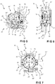
- FIG. 5 to 7 show the socket 10 of the travel adapter 100 described above with the plugs 20, 20 ', 20 “, 20”' arranged thereon, the housing 101 being hidden in these figures.
- the connectors 20, 20 ', 20 “, 20”' are in accordance with the British standard (connector 20), the American standard (connector 20 '), the Swiss standard (connector 20 ") and the Australian standard (connector 20"') educated. Plugs of other standards can also be arranged on a travel adapter 100 described here.
- the plugs 20, 20 ', 20 “, 20”' each have a first contact pin 21, 21 ', 21 ", 21”' and a second contact pin 22, 22 ', 22 ", 22"'.
- the plugs 20, 20 ', 20 “, 20”' shown require a protective conductor pin, which is shown as a third contact pin 23, 23 ', 23 “, 23”'.
- Contact elements 16, 17, 18 are arranged in the socket housing 15, each of which is electrically connected to the first contact socket 11, the second contact socket 12 and the third contact socket 13 and / or to the contact tongues 14, 14 'of the socket 10.
- the third contact pin 23, 23 ', 23 ", 23”' with the contact tongues 14, 14 'of the socket 10 and / or with the third contact socket 13 and with the contact element 18 form a protective conductor connection.
- the contact elements 16, 17, 18 in the socket housing 15 can each be electrically connected to the respective plug 20, 20 ', 20 ", 20”' by rotating the socket 10 relative to the housing 101.
- the contact elements 16, 17, 18 with the respective first contact pin 21, 21 ', 21 ", 21"', with the respective second contact pin 22, 22 ', 22 “, 22”' and with the respective third contact pin 23, 23 ', 23 ", 23”' brought into contact and thus electrically connected.
- Plugs according to a standard without a protective conductor pin have no third contact pin 23, 23 ', 23 ", 23"'. That contact element 18, which is electrically connected to the contact socket 13 or the contact tongues 14, 14 ', is electrically isolated from a plug without a third contact pin 23, 23', 23 ", 23"'by being removed from the housing or from a connector cover is covered (not shown).
- the selection mark 19 on the box housing 15 ( Fig. 2 ) is arranged in the area above the contact elements 16, 17, 18, so that the user of the travel adapter 100 can see which plugs 20, 20 ', 20 ", 20”' are used to electrically connect the contact sockets 11, 12, 13, 14, 14 ' are connected.
- the respectively selected connector 20, 20 ', 20 ", 20”' or its contact pins 21, 22, 23; 21 ', 22', 23 '; 21 ", 22", 23 “;21”', 22 “', 23”' are pivoted out of the housing by the user.
- the first contact pin 21, 21 ', 21 “, 21”', the second contact pin 22, 22 ', 22 “, 22”' and the third contact pin 23, 23 ', 23 “, 23”' are coupled to one another, such that they can be swung out of the housing together.
- the contact pins 21, 22, 23; 21 ', 22', 23 '; 21 ", 22", 23 “;21”', 22 “', 23”'gear used, which are arranged on the box housing 15.
- the contact pins 21, 22, 23; 21 ', 22', 23 '; 21 ", 22", 23 “;21”', 22 “', 23”' have contact clips 29, which each interact with the contact elements 16, 17, 18 on the socket housing, provided one of the plugs 20, 20', 20 ", 20”'is in its operating position.
- the gears are designed either as gearwheels 30 or as coupling rod gears 40.
- a gearbox enables the respective contact pins 21, 22, 23; 21 ', 22', 23 '; 21 "', 22"', 23 “', so that they can move synchronously into their operating position and / or rest position.
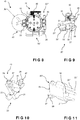
- the gear mechanism 30 has toothings 31, 32 which engage in one another and enable the contact pins 21 ', 22', 23 'to pivot out together.
- the gears 31, 32 rotate in opposite directions.
- a gear notch 33 is arranged on the gear unit, so that the third contact pin 23 ′ is arranged in the gear notch 33 in its pivoted-in rest position, and the size of the travel adapter can thus be minimized.
- a coupling rod gear 40 connects the contact pins 21, 22, 23.
- the coupling rod gear 40 has a connecting rod 41, which enables the contact pins 21, 22, 23 to be pivoted out together.
- the contact pins 21 and 22 are congruent, so that only the contact pin 21 can be shown.
- the first contact pin 21, 21 'and the second contact pin 22, 22' can be pivoted out in a first pivoting direction and the third contact pin 23; 23 'can be swiveled out in a second swivel direction opposite to the first swivel direction.
- Fig. 11 shows a plug 20 "in accordance with the Swiss standard, the Italian standard and the Brazilian standard, these standards being selectable.
- the third contact pin 23" as the protective conductor pin can be moved linearly.
- the protective conductor pin is arranged in a slot 36 between the first contact pin 21 "and the second contact pin 22" linearly movable.
- the unlocking mechanism 50 has an unlocking link 51 and an engagement element 52.
- the unlocking link 51 and the engaging element 52 cooperate in such a way that reliable unlocking is possible.
- the engaging element 52 is arranged on the gear 30 of the plug 20 'and the unlocking link 51 is arranged on the socket housing 15.
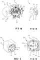
- the 14 to 19 show a further travel adapter 400 according to the invention in different views.
- the travel adapter 400 comprises a housing 401 in which a socket 410 with a first standard is arranged and in which a plug 420 with a standard different from the first standard is arranged.
- the norm shown of the plug 420 corresponds to the British standard.
- the socket 410 is designed to accommodate external plugs of different standards.
- the socket has a first contact socket 411, a second contact socket 412 and a third contact socket 413 as well as contact tongues 414, 414 '.
- the third contact socket 413 has an elongated hole, so that an external plug according to the Swiss plug standard, the Italian plug standard and the Brazilian plug standard can be arranged in the socket 410, for example a plug as in FIG Fig. 11 shown.
- the plug 420 is arranged on the side of the housing 401 opposite the socket 410.
- the plug 420 has a first contact pin 421 and a second contact pin 422, the first contact socket 412 being electrically connected to the first contact socket 411 and the second contact pin 422 being electrically connected to the second contact socket 412.
- the plug 420 has a third contact pin 423, which is a protective conductor pin, and which is electrically connected to the third contact socket 413 or to the contact tongues 414, 414 '.
- the contact pins 421, 422, 423 are movably arranged on the housing 401, so that they can be pivoted out of the housing 401. Their end position pivoted out of the housing 401 is referred to as the operating position ( Fig. 18 ). In the operating position, the contact pins 421, 422, 423 can be inserted into the respective contact sockets of an external plug. In contrast, the rest position is the end position poured in, in which the contact pins 421, 422, 423 are located in the housing 401 ( Fig. 16 ).
- the contact pins 421, 422, 423 are, as already in the 9 or 10 described coupled with each other, such that they can be moved together out of the housing 401.
- the travel adapter 400 has a gear and the contact pins 21, 22 and the contact pin 23 have different pivoting directions.
- Widening elements 425 are arranged on the housing 401 and can be moved into an activation position by moving the first contact pin 421 and the second contact pin 422 out.
- the widening elements 425 can be moved by means of a link guide 426, as already shown in FIG Fig. 1 described.
- the widening elements can optionally be activated with the aid of a triggering device.
- the user can activate the trigger device 418, for example via a trigger button 419 (dashed circle), which releases the widening elements 425, so that they are moved from their inactive position to their activation position.
- the contact pins 421, 422, 423 can then be moved out of the housing 401.
- the release button 419 can be arranged on the housing 401 of the travel adapter 400 so that it is easily accessible to the user.
- a trigger slide can also be used as the trigger button 419.
- the travel adapter 400 can further elements of the travel adapter 100 according to the 1 to 13 exhibit.
- the travel adapter 400 has an interface 480, which makes it possible to arrange an additional module as described here on the travel adapter 400 and to electrically connect the additional module arranged at the interface 480 to the socket 410.
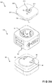
- Fig. 20 shows a set 500 according to the invention comprising a travel adapter 100 as described here with an additional module 90 and a plug adapter 200.
- the plug adapter 200 has a plug adapter housing 201, on which a plug 220 for interacting with the socket 10 of the travel adapter 100 is arranged, and one or several sockets 210 of different standards.
- the plug-in adapter 200 has an essentially disk-shaped plug-in adapter housing 201, so that the set 500 can be of compact construction in the assembled state.
- the plug 220 of the plug adapter 200 has a first standard and the socket 10 of the travel adapter 100 has at least the same standard, so that the plug 220 can be plugged into the socket 10 of the travel adapter 100 and can thus be electrically connected to it.
- the socket 210 of the plug adapter 200 has several standards, so that contact pins of plugs of different standards can be connected to this socket 210.
- the socket 210 has a plurality of contact sockets 211.
- the travel adapter 100; 400 has an interface 80; 480 on (see Fig. 3 ; Fig. 16 ).
- the additional module 90 has cams 95.
- the interface 80; 480 of travel adapter 100; 400 on the cams 95 of the additional module 90 so that they interact mechanically.
- At least one cam 95 has an electrical contact 96 which is in contact with a contact in the interface 80; 480 is electrically connectable, so that the additional module 90 can be supplied with electrical energy when the travel adapter 100; 400 is connected to an external power supply.
- the additional module 90 is, for example, either a USB charger module, a mobile battery module, a Bluetooth module, a WiFi module, a wireless charger module, an IoT (Internet of Things) module, a night light module, a compartment for a cable , Smartphone holder module, smart meter module (in particular with a voltage, current and power display), key finder module, smoke detector module, mosquito repellent module or room fragrance module.
- a USB charger module for example, either a USB charger module, a mobile battery module, a Bluetooth module, a WiFi module, a wireless charger module, an IoT (Internet of Things) module, a night light module, a compartment for a cable , Smartphone holder module, smart meter module (in particular with a voltage, current and power display), key finder module, smoke detector module, mosquito repellent module or room fragrance module.
- an electrical device such as a smartphone, a tablet or a music player, can be connected to the USB charger module, so that the battery arranged therein can be charged.
- the previously described set 500 can, instead of the travel adapter 100, also the travel adapter 400, as previously described and in FIGS 14 to 19 shown include.
Landscapes
- Details Of Connecting Devices For Male And Female Coupling (AREA)
- Percussion Or Vibration Massage (AREA)
- Control And Safety Of Cranes (AREA)
- Vehicle Body Suspensions (AREA)
- Connector Housings Or Holding Contact Members (AREA)
Abstract
Description
- Die Erfindung betrifft Reiseadapter sowie ein Set umfassend den Reiseadapter.
- Elektrische Adapter, insbesondere sogenannte Reiseadapter sind an sich bekannt. Sie bestehen zumindest aus einem Stecker und zumindest aus einer Steckdose. Der Stecker weist eine Kontakteinrichtung auf, die an länderabhängige Normen (kurz: Normen) der Steckdose angepasst oder anpassbar ist. Die Steckdose weist zumindest zwei Kontaktöffnungen auf, die derart geformt und zueinander beabstandet sind, dass eine Kontakteinrichtung eines Netzsteckers z. B. elektrischen Geräts, beispielsweise die Kontakteinrichtung des Netzsteckertyps C (CEE 7/16), mit diesem verbindbar ist.
- Die
EP 1 257 018 B1 offenbart einen elektrischen Steckadapter zum wahlweisen Anschluss eines Stecksystems als Stecker an unterschiedliche länderspezifische Stecksysteme. Der Steckadapter weist ein Gehäuse auf, an dessen Aussenumfang mehrere unterschiedliche vorstehende Stecksysteme angeordnet sind und weist einen Steckdosentopf als Steckdose auf, der in dem Gehäuse drehbar gelagert ist. Der Steckdosentopf weist elektrische Kontakte auf, die in jeweils den äusseren Stecksystemen zugeordneten Drehstellungen des Steckdosentopfes mit entsprechenden elektrischen Kontakten der jeweiligen Stecksysteme verbindbar sind, wobei eines der Stecksysteme einen im Gehäuse bewegbar gelagerten Schutzkontaktstift aufweist. - Die
D 199 02 642 A1 - Nachteilig an diesen bekannten Lösungen ist, dass diese einen komplexen Aufbau aufweisen und dadurch einen unerfahrenen Benutzer einerseits bei der richtigen Verwendung des Reiseadapters verunsichern und andererseits den Benutzer nicht vor einer falschen Benutzung des Reiseadapters im jeweiligen Land schützen.
- Es ist die Aufgabe der vorliegenden Erfindung, einen oder mehrere Nachteile des Standes der Technik zu beheben. Insbesondere soll ein Reiseadapter geschaffen werden, der in Ländern mit unterschiedlichen Normen verwendbar ist und dessen Handhabung für den Benutzer in den jeweiligen Ländern verbessert wird. Insbesondere soll ein Set umfassend den Reiseadapter geschaffen werden, dass in vielen Ländern einfach einsetzbar ist und dessen Handhabung verbessert wird.
- Diese Aufgabe wird durch die in den unabhängigen Ansprüchen definierten Vorrichtungen gelöst. Vorteilhafte Weiterbildungen sind in den Figuren, der Beschreibung und insbesondere in den abhängigen Patentansprüchen dargelegt.
- Ein erfindungsgemässer Reiseadapter umfasst ein Gehäuse, zumindest eine Steckdose einer ersten Norm und zumindest einen Stecker einer zweiten Norm. Die Steckdose der ersten Norm weist zumindest eine erste Kontaktbuchse und eine zweite Kontaktbuchse auf und der Stecker der zweiten Norm weist zumindest einen ersten Kontaktstift und einen zweiten Kontaktstift auf. Der Stecker ist an dem Gehäuse angeordnet und die Steckdose ist drehbar in dem Gehäuse gelagert. Die Steckdose weist ein Dosengehäuse auf, wobei in dem Dosengehäuse Kontaktelemente angeordnet sind, die jeweils mit der ersten Kontaktbuchse und der zweiten Kontaktbuchse der Steckdose verbunden sind. Die Kontaktelemente sind durch ein Verdrehen der Steckdose relativ zum Gehäuse, in eine dem jeweiligen Stecker entsprechende Betriebsposition, jeweils elektrisch mit dem ersten Kontaktstift oder dem zweiten Kontaktstift des jeweiligen Steckers verbindbar. Der Stecker oder der erste Kontaktstift und der zweite Kontaktstift sind schwenkbar am Gehäuse angeordnet, derart, dass der Stecker oder der erste Kontaktstift und der zweite Kontaktstift aus dem Gehäuse herausschwenkbar sind.
- Mit dem erfindungsgemässen Reiseadapter kann der Benutzer mit der Auswahl des gewünschten Landes am Reiseadapter, nur den dort geeigneten Stecker, oder nur den dort geeigneten ersten Kontaktstift und zweiten Kontaktstift, in die Betriebsposition bewegen. Dabei gibt es für den Stecker oder für den ersten Kontaktstift und den zweiten Kontaktstift nur eine einzige Betriebsposition. Somit kann eine zweifelsfreie und korrekte Verwendung des Reiseadapters im gewünschten Land gewährleistet werden. Der Benutzer wird mithilfe dieses Reiseadapters davor geschützt, verschiedene Stecker im jeweiligen Land auszuprobieren zu müssen. Damit wird einerseits die Handhabung verbessert und andererseits eine hohe Sicherheit in der Anwendung gewährleistet.
- Die Betriebsposition ist jene herausgeschwenkte Endposition, in welcher der Stecker oder der erste Kontaktstift und der zweite Kontaktstift in eine externe bzw. separate Steckdose gesteckt werden können. Im Gegensatz dazu ist eine Ruheposition jene hineingeschwenkte Endposition, in welcher sich der Stecker oder der erste Kontaktstift und der zweite Kontaktstift zumindest abschnittsweise eingeschwenkt im Gehäuse befinden.
- Der Stecker oder der erste Kontaktstift und der zweite Kontaktstift sind derart angeordnet, dass diese aus der Ruheposition am Gehäuse herausschwenkbar sind. Dabei kann der Stecker oder der erste Kontaktstift und der zweite Kontaktstift im Wesentlichen frei am Gehäuse angeordnet sein, sodass deren funktionelle Verwendung im Wesentlichen vergleichbar ist zur Anordnung des Steckers oder des ersten Kontaktstifts und des zweiten Kontaktstifts im Gehäuse. Die Anordnung im Gehäuse verhindert ein Verhaken des Steckers oder des ersten Kontaktstifts und des zweiten Kontaktstifts mit weiteren Gegenständen, beispielsweise mit Gegenständen, wie Gepäck, welches sich unmittelbar in der Umgebung des Reiseadapters befindet
- Bevorzugt sind die jeweiligen Kontaktelemente mit den jeweiligen Kontaktbuchsen einteilig ausgebildet. Damit kann verhindert werden, dass sich die Kontaktelemente von den Kontaktbuchsen im Gehäuse voneinander lösen können, wodurch sich die Funktionsbeständigkeit des Reiseadapters verbessern lässt.
- Bevorzugterweise sind der erste Kontaktstift und der zweite Kontaktstift miteinander gekoppelt, derart, dass sie gemeinsam aus dem Gehäuse herausschwenkbar sind. Der erste Kontaktstift und der zweite Kontaktstift können damit synchron von deren Ruheposition in deren Betriebsposition bewegt werden. Diese erreichen somit gleichzeitig deren Betriebsposition, sodass diese vom Benutzer einfach in eine externe bzw. separate Steckdose gesteckt werden können.
- Vorzugsweise weist die Steckdose eine Kontaktzunge zur Herstellung einer Schutzleiterverbindung auf und der Stecker einen dritten Kontaktstift als Schutzleiterpin auf, wobei in dem Dosengehäuse ein drittes Kontaktelement angeordnet ist, das mit der Kontaktzunge verbunden ist und wobei der erste Kontaktstift und der zweite Kontaktstift und der dritte Kontaktstift miteinander gekoppelt sind, derart, dass sie gemeinsam aus dem Gehäuse herausschwenkbar sind. Damit ist der Reiseadapter auch in jenen Ländern einsetzbar, in denen ein Schutzleitersystem gefordert wird. Die Kontaktzunge ist mithilfe des dritten Kontaktelements mit dem dritten Kontaktstift verbindbar. Dabei ist das dritte Kontaktelement am Dosengehäuse angeordnet und somit drehbar in dem Gehäuse des Reiseadapters gelagert. Die Koppelung der Kontaktstifte ermöglicht eine synchrone Bewegung aller drei Kontaktstifte, sodass diese einfach in deren jeweilige Betriebsposition bewegt werden können.
- Bevorzugt ist der dritte Kontaktstift linear bewegbar. Dabei kann der dritte Kontaktstift als Schutzleiterpin ausgebildet sein, welcher sich zwischen dem ersten Kontaktstift und dem zweiten Kontaktstift befinden kann. Der Schutzleiterpin kann dabei normal zur Verbindungsgerade, welche sich zwischen dem ersten Kontaktstift und dem zweiten Kontaktstift erstreckt, bewegbar sein. Beispielsweise weist ein Stecker mit einem linear bewegbaren Schutzleiterpin ein Langloch auf, in welchem sich der Schutzleiterpin linear bewegen kann. Eine lineare Bewegung ist in diesem Zusammenhang eine Bewegung entlang der Längsausstreckung des Langloches. Damit lassen sich mit einem und demselben Stecker die Schweizer Steckernorm, die italienische Steckernorm sowie die brasilianische Steckernorm abdecken.
- Alternativ oder ergänzend zur Kontaktzunge weist die Steckdose eine dritte Kontaktbuchse zur Herstellung einer Schutzleiterverbindung auf. Wie zuvor beschrieben, kann auch die dritte Kontaktbuchse mithilfe des dritten Kontaktelements mit dem dritten Kontaktstift verbunden werden. Zusätzlich zu den zuvor genannten Vorteilen weist ein Reiseadapter mit drei Kontaktbuchsen einen einfachen Aufbau auf, der einen externen bzw. separaten Stecker nach dem Einstecken in die Steckdose stabil hält.
- Bevorzugt sind der erste Kontaktstift und der zweite Kontaktstift in eine erste Schwenkrichtung herausschwenkbar und der dritte Kontaktstift in eine der ersten Schwenkrichtung gegenläufige zweiten Schwenkrichtung herausschwenkbar. Damit lassen sich die Kontaktstifte platzsparend in der Ruheposition im Gehäuse des Reiseadapters anordnen. Der dritte Kontaktstift ist als der Schutzleiterpin ausgebildet, sodass dieser gegenläufig zu den ersten und zu dem zweiten Kontaktstift schwenkbar ist.
- Ergänzend zum zuvor Beschriebenen kann der dritte Kontaktstift sowohl linear bewegbar wie auch schwenkbar bewegbar sein. Damit ist der als Schutzleiterpin ausgebildete dritte Kontaktstift besonders flexibel einsetzbar.
- Bevorzugterweise ist zur Koppelung ein Getriebe vorgesehen. Ein Getriebe für die gemeinsam herausschwenkbaren Kontaktstifte bewirkt ein synchrones Bewegen dieser Kontaktstifte beim Herausschwenken in deren Betriebsposition.
- Insbesondere ist zur Koppelung der Kontaktstifte ein Zahnradgetriebe vorgesehen. Ein Zahnradgetriebe weist Verzahnungen auf, welche eine effiziente Kopplung der gemeinsam herausschwenkbaren Kontaktstifte ermöglicht, wobei das Zahnradgetriebe einen kompakten Aufbau aufweist. Die Kontaktstifte können mithilfe der Verzahnungen präzise von deren Ruhepositionen in deren Betriebspositionen und wieder zurückbewegt werden.
- Alternativ oder ergänzend ist ein Koppelstangengetriebe als Koppelung der Kontaktstifte vorgesehen. Ein Koppelstangengetriebe ermöglicht eine besonders zuverlässige Kopplung der gemeinsam zu bewegenden Kontaktstifte. Damit werden die Kontaktstifte mechanisch kaum beansprucht, wodurch die Lebensdauer des Reiseadapters verlängert werden kann.
- Insbesondere ist an dem Getriebe eine Getriebekerbe zum Aufnehmen von zumindest einem der Kontaktstifte vorgesehen. Damit ist ein verbesserter kompakter Aufbau des Reiseadapters möglich, da die Kontaktstifte in deren Ruheposition platzsparend im Gehäuse angeordnet sind. Beispielsweise ist der dritte Kontaktstift in seiner eingeschwenkten Ruheposition in der Getriebekerbe angeordnet.
- Vorzugsweise weist der Reiseadapter einen Entriegelungsmechanismus auf, der ein Herausschwenken des jeweiligen Steckers oder des ersten Kontaktstiftes und des zweiten Kontaktstiftes ermöglicht, wenn sich die Steckdose in der jeweiligen Betriebsposition befindet. Gleichzeitig kann der Entriegelungsmechanismus das Herausschwenken der übrigen Stecker oder ersten Kontaktstifte und zweiten Kontaktstifte verhindern, sodass diese zwingend in deren Ruheposition verbleiben. Damit kann der Benutzer nach der Auswahl der gewünschten Norm nur mehr den dafür passenden Stecker oder ersten Kontaktstift und zweiten Kontaktstift verwenden.
- Bevorzugterweise ist der Entriegelungsmechanismus zumindest zweiteilig ausgebildet und weist eine Entriegelungskulisse und ein Eingriffselement auf. Die Entriegelungskulisse und das Eingriffselement wirken dabei derart zusammen, dass ein zuverlässiges Entriegeln möglich ist und ein Verklemmen der Stecker und/oder der Kontaktstifte verhindert werden kann. Vorteilhaft ist der Entriegelungsmechanismus zweiteilig ausgebildet, sodass dieser einen einfachen konstruktiven Aufbau aufweist.
- Bevorzugt ist die Entriegelungskulisse am Dosengehäuse und das Eingriffselement ist am Stecker angeordnet. Die Anordnung der Entriegelungskulisse an dem Dosengehäuse ermöglicht eine stabile Betätigung des Entriegelungsmechanismus beim Drehen der Steckdose. Das Eingriffselement kann an dem Stecker oder an dem ersten Kontaktstift und/oder zweiten Kontaktstift, aber auch an der Kopplung bzw. am Getriebe, angeordnet sein, sodass das Eingriffselement nahe an dem Dosengehäuse angeordnet werden kann und somit ein zuverlässiges und stabiles Zusammenwirken der Entriegelungskulisse und des Eingriffselements möglich ist.
- Vorzugsweise weist der Reiseadapter eine Aufnahme für eine Überstromsicherung auf. Reiseadapter werden in unterschiedlichen Ländern mit unterschiedlichen Energienetzen eingesetzt. Eine Überstromsicherung ist dabei für das sichere Verwenden des Reiseadapters von Vorteil und kann hinsichtlich länderspezifischen Zertifizierungsbestimmungen notwendig sein. Sofern am Reiseadapter ein beschädigtes Gerät angeschlossen wird, verhindert die Überstromsicherung eine Beschädigung des Reiseadapters, da dabei die Überstromsicherung auslöst. Die Aufnahme gewährleistet ein einfaches Austauschen der Überstromsicherung.
- Insbesondere ist die Aufnahme am Dosengehäuse angeordnet. Damit kann die Aufnahme und somit die darin angeordnete Überstromsicherung nahe an den Kontaktbuchsen angeordnet werden.
- Bevorzugt ist die Aufnahme der Steckdose gegenüberliegend angeordnet. Damit kann die Baugrösse des Reiseadapters klein gehalten werden.
- Insbesondere ist die Überstromsicherung eine Schmelzsicherung. Schmelzsicherungen können für unterschiedliche Überstromsicherungsklassen hergestellt werden und weisen eine kompakte Bauform sowie ein geringes Eigengewicht auf.
- Vorteilhaft ist die Aufnahme in der aus dem Dosengehäuse herausgeführten Position nicht von dem Dosengehäuse separierbar. Damit kann die Aufnahme nicht verloren gehen. Gleichzeitig kann somit sichergestellt werden, dass die Kontaktbuchsen oder die Kontaktelemente im Dosengehäuse nicht berührt werden können.
- Bevorzugterweise weist der Reiseadapter zum Verriegeln der Aufnahme eine Verriegelungsvorrichtung auf. Die Verriegelungsvorrichtung verhindert den Zugang zu der Überstromsicherung, wenn sich einer der Stecker oder Kontaktstifte in deren Betriebsposition befinden. Damit wird eine sichere Verwendung des Reiseadapters weiter verbessert.
- Bevorzugt ist die Verriegelungsvorrichtung zumindest zweiteilig ausgebildet und weist einen Verriegelungsnocken sowie eine Verriegelungsnut auf. Die Verriegelungsnocken und die Verriegelungsnut greifen fest ineinander und verhindern ein Öffnen der Aufnahme.
- Bevorzugt ist die Verriegelungsnut am Gehäuse angeordnet und der Verriegelungsnocken an der Aufnahme angeordnet. Dies ermöglicht ein stabiles Zusammenwirken dieser Elemente der Verriegelungsvorrichtung am Reiseadapter.
- Insbesondere sind die Verriegelungsnut und der Verriegelungsnocken in einer Position des Dosengehäuses in Wirkverbindung bringbar, sodass die Aufnahme dem Dosengehäuse lösbar ist. Diese Position ist zu jeder Betriebsposition der Stecker oder Kontaktstifte unterschiedlich. Damit kann gewährleistet werden, dass die Überstromsicherung nur dann entnommen werden kann, wenn sich alle Stecker oder Kontaktstifte in deren Ruheposition befinden und somit der Reiseadapter nicht im elektrischen Kontakt mit einem externen Energienetz befindet.
- Vorzugsweise weist der Reiseadapter eine Schnittstelle auf, die es ermöglicht, ein Zusatzmodul am Reiseadapter anzuordnen und dieses Zusatzmodul elektrisch mit der Steckdose zu verbinden. Damit ist zusätzlich ein elektrisches Gerät mit dem Reiseadapter verbindbar, sodass die Einsatzbandbreite des hier vorliegend beschriebenen Reiseadapters weiter verbessert wird.
- Vorteilhaft weist die Schnittstelle einen elektrischen Kontakt auf, der mit einem elektrischen Kontakt an dem Zusatzmodul zusammenwirkt, sodass das Zusatzmodul mit elektrischer Energie versorgt werden kann.
- Insbesondere (nicht abschliessend) ist das Zusatzmodul aus der Gruppe eines USB-Ladegerät-Moduls, mobiles Akkumulator-Modul, Bluetooth®-Moduls, WiFi-Moduls , Drahtloses Ladegerät-Modul , IoT (Internet of Things)-Modul, Nachtlicht-Modul, Aufnahmefach-Modul für ein Kabel, Smartphone-Halterungs-Modul, Smart-Meter-Modul (insbesondere mit einer Spannung-, Strom- und Leistungsanzeige), Key-Finder-Modul, Rauchmelder-Modul, Mückenschreck-Modul oder Raum-Duft-Modul.
- Beispielsweise kann an das USB-Ladegerät-Modul ein elektrisches Gerät, wie ein Smartphone, Tablet oder ein Musikwiedergabegerät angeschlossen werden, sodass der darin angeordnete Akkumulator geladen werden kann.
- Bevorzugterweise weist der Reiseadapter zumindest eine Griffmulde zum Verdrehen der Steckdose auf. Die zumindest eine Griffmulde erleichtert dem Benutzer des Reiseadapters das Hantieren des Reiseadapters. Dabei kann der Benutzer den Reiseadapter mit einer Hand festhalten und die Steckdose des Reiseadapters mit der anderen Hand in die gewünschte Position verdrehen.
- Bevorzugt ist diese Griffmulde am Dosengehäuse angeordnet. Damit wird die Haptik für den Benutzer des Reiseadapters verbessert und somit das Verdrehen der Steckdose vereinfacht.
- Insbesondere ist diese Griffmulde an der Schnittstelle angeordnet. Somit sind die Griffmulde und die Schnittstelle am gleichen Bauteil des Gehäuses angeordnet, wodurch die Griffmulde und der Schnittstelle in einem Arbeitsschritt hergestellt werden können. Gegebenenfalls kann die Steckdose mithilfe eines an der Schnittstelle angeordneten Zusatzmoduls verdreht werden.
- Bevorzugt weist der Reiseadapter zwei Griffmulden zum Verdrehen der Steckdose auf. Dabei kann der Benutzer beispielsweise mit je einem Finger in eine der Griffmulden eingreifen und die Steckdose verdrehen. Die zwei Griffmulde ermöglichen einen sicheren Halt beim Verdrehen der Steckdose. Die zwei Griffmulden sind vorteilhaft an einander gegenüberliegenden Positionen angeordnet, womit eine einfache Handhabung ermöglicht ist.
- Bevorzugterweise ist die Steckdose im Dosengehäuse mit Steckern der brasilianischen, italienischen und Schweizer Norm kompatibel. Dabei kann die Steckdose im Dosengehäuse auch mit Steckern Typ J, Typ L oder Typ N kompatibel sein, wodurch die Flexibilität des Reiseadapters erhöht wird.
- Vorzugsweise ist am Reiseadapter zum Herausschwenken des Steckers zumindest eine Betätigungsmulde vorgesehen. Nachdem der Benutzer des Reiseadapters jenen Stecker der gewünschten Norm ausgewählt hat und die Steckdose in die dafür vorgesehene Position gedreht hat, kann der Benutzer in die Betätigungsmulde eingreifen und den ausgewählten Stecker einfach und weitgehend widerstandslos aus dem Gehäuse herausschwenken.
- Alternativ oder ergänzend ist am Reiseadapter zum Herausschwenken der ersten Kontaktstifte und der zweiten Kontaktstifte zumindest eine Betätigungsmulde vorgesehen. Wie zuvor beschrieben, kann der Benutzer die Betätigungsmulde verwenden, um den ersten Kontaktstift und den zweiten Kontaktstift einfach aus dem Gehäuse herauszuschwenken, wodurch die Handhabung für den Benutzer verbessert wird. Weiters kann mithilfe der Betätigungsmulde sichergestellt werden, dass alle Kontaktstifte aus dem Gehäuse herausgeschwenkt werden können.
- Bevorzugterweise ist am Stecker ein Einrastnocken zum Zusammenwirken mit dem Gehäuse angeordnet, derart, dass der Stecker in einer Ruheposition im Gehäuse und in einer herausgeschwenkten Betriebsposition arretierbar ist. Damit wird der Stecker daran gehindert, entweder die Ruheposition oder die herausgeschwenkte Betriebsposition ungewollt zu verlassen, wodurch die Betriebssicherheit des Reiseadapters verbessert wird.
- Alternativ oder ergänzend ist an den ersten Kontaktstiften und den zweiten Kontaktstiften ein Einrastnocken zum Zusammenwirken mit dem Gehäuse angeordnet, derart, dass der erste Kontaktstift und der zweite Kontaktstift in einer Ruheposition im Gehäuse und in einer herausgeschwenkten Betriebsposition arretierbar sind. Damit werden die Kontaktstifte daran gehindert, entweder die Ruheposition oder die herausgeschwenkte Betriebsposition ungewollt zu verlassen, wodurch die Betriebssicherheit des Reiseadapters verbessert wird.
- Vorzugsweise ist am Gehäuse zumindest ein Verbreiterungselement angeordnet. Das zumindest eine Verbreitungselement ermöglicht ein stabiles Anliegen des Dosengehäuses an einer externen Steckdose, wenn der Reiseadapter mit einem Stecker oder einem ersten Kontaktstift und einem zweiten Kontaktstift in der externen Steckdose angeordnet ist.
- Vorzugsweise weist das Gehäuse des Steckers gemäss der britischen Norm ein zumindest ein Verbreiterungselement auf. Das Verbreiterungselement ermöglicht eine platzsparende Anordnung der verhältnismässig breiten Kontaktstifte aus der britischen Norm im Gehäuse des Reiseadapters.
- Darüber hinaus kann eine Norm für Reiseadapter, beispielsweise die britische Norm, eine minimale Grundfläche für jene Gehäuseseite des Reiseadapters vorgeben, an denen der Stecker oder die Kontaktstifte angeordnet sind. Weiters kann diese Norm oder eine weitere Norm verlangen, dass die herausgeschwenkten Kontaktstifte einen vorgegebenen Abstand zu zumindest einem Randbereich der Gehäuseseite aufweisen. Um die für diese Norm vorgegebene Grundfläche bzw. den dafür vorgegebenen Abstand zu zumindest einem Randbereich zu erfüllen, weist der hier vorliegend beschriebene Reiseadapter vorteilhaft zumindest ein Verbreiterungselement auf.
- Insbesondere ist das zumindest eine Verbreiterungselement mittels einer Kulissenführung durch das Herausschwenken des Steckers in eine Aktivierungsposition bewegbar. Die Kulissenführung ermöglicht ein stabiles Bewegen des zumindest einen Verbreiterungselements in dessen Aktivierungsposition, wodurch ein mehrmaliges Bewegen des zumindest einen Verbreitungselements verschleissfrei ausgeführt werden kann.
- Alternativ oder ergänzend ist das zumindest eine Verbreiterungselement mittels einer Kulissenführung durch das Herausschwenken des ersten Kontaktstiftes und des zweiten Kontaktstiftes in eine Aktivierungsposition bewegbar. Damit wird ein zusätzlicher Antriebsmechanismus für die Bewegung der Verbreitungselemente gespart, womit der Reiseadapter leicht und kompakt gebaut werden kann.
- In der Aktivierungsposition sind die Verbreiterungselemente soweit aus dem Gehäuse herausbewegt, dass die daraus resultierende Grundfläche an der Gehäuseseite den Anforderungen der relevanten Norm entspricht.
- In der Inaktivposition hingegen sind die Verbreiterungselemente im Gehäuse angeordnet, damit der Reiseadapter möglichst kompakt bleibt. Damit kann die für den Benutzer des Reiseadapters vorteilhaften Eigenschaften, wie leichte, kleine und kompakte Bauform ausreichend erfüllt werden.
- Insbesondere ist am Gehäuse zumindest ein weiteres Verbreiterungselement angeordnet, das mittels einer Kulissenführung durch das Herausschwenken des ersten Kontaktstiftes und des zweiten Kontaktstiftes in eine Aktivierungsposition bewegbar ist. Das zumindest eine weitere Verbreitungselement ermöglicht ein noch stabileres Anliegen des Dosengehäuses an einer externen Steckdose.
- Ein weiterer erfindungsgemässer Reiseadapter umfasst ein Gehäuse, zumindest eine Steckdose einer ersten Norm und zumindest einen Stecker einer zweiten Norm, wobei die Steckdose der ersten Norm zumindest eine erste Kontaktbuchse und eine zweite Kontaktbuchse aufweist und der Stecker der zweiten Norm zumindest einen ersten Kontaktstift und einen zweiten Kontaktstift aufweist. Der erste Kontaktstift ist mit der ersten Kontaktbuchse elektrisch verbunden und der zweite Kontaktstift ist mit der zweiten Kontaktbuchse elektrisch verbunden. Der erste Kontaktstift und der zweite Kontaktstift sind bewegbar am Gehäuse angeordnet. Am Gehäuse ist zumindest ein Verbreiterungselement angeordnet, wobei dieses in einer Aktivierungsposition bewegbar ist.
- Das zumindest eine aktivierte Verbreitungselement ermöglicht eine normkonforme Grundfläche und ein stabiles Anliegen des Gehäuses des Reiseadapters an einer externen Steckdose (Netzsteckdose), wenn der erste Kontaktstift und der zweite Kontaktstift in den Kontaktbuchsen einer externen Steckdose angeordnet sind. Darüber hinaus ermöglicht das zumindest eine Verbreiterungselement einen kompakten Aufbau des Reiseadapters, wodurch die Grösse des Reiseadapters weiter verkleinert werden kann. Die Aktivierungsposition des zumindest einen Verbreitungselements kann dann erreicht sein, wenn sich der erste Kontaktstift und der zweite Kontaktstift in deren Betriebsposition befinden. Im Gegensatz können sich die Verbreiterungselemente in einer Inaktivposition befinden, wenn sich der erste Kontaktstift und der zweite Kontaktstift in deren Ruheposition befinden. In der Inaktivposition sind die Verbreiterungselemente abschnittsweise im Gehäuse angeordnet und bilden mit den Gehäuseseiten eine platzsparende, kompakte Einheit. Damit kann die für den Benutzer des Reiseadapters vorteilhaften Eigenschaften, wie leichte, kleine und kompakte Bauform ausreichend erfüllt werden.
- Die Betriebsposition des ersten Kontaktstifts und des zweiten Kontaktstifts ist jene herausbewegte Endposition, in welcher der erste Kontaktstift und der zweite Kontaktstift in eine externe bzw. separate Steckdose gesteckt werden können. Im Gegensatz dazu ist eine Ruheposition jene hineinbewegte Endposition, in welcher sich der erste Kontaktstift und der zweite Kontaktstift zumindest abschnittsweise im Gehäuse befinden.
- Bevorzugt ist das zumindest eine Verbreiterungselement derart am Gehäuse angeordnet, dass dies durch das Herausbewegen des ersten Kontaktstiftes und des zweiten Kontaktstiftes in eine Aktivierungsposition bewegbar ist.
- Alternativ dazu kann der Reiseadapter eine Auslösevorrichtung zum Aktivieren des zumindest einen Verbreiterungselements aufweisen. Dabei kann der Benutzer die Auslösevorrichtung, beispielsweise über einen Auslöseknopf, aktivieren, die das zumindest eine Verbreiterungselement freigibt, sodass dieses von dessen Inaktivposition in dessen Aktivierungsposition bewegt wird. Dabei kann die Auslösevorrichtung ein Getriebe aufweisen, welches im Gehäuse des Reiseadapters angeordnet sein kann und welches den Auslöseknopf mit den Kontaktstiften verbindet, sodass mithilfe des Getriebes die Kontaktstifte aus dem Gehäuse herausbewegt werden können. Der Auslöseknopf kann am Gehäuse des Reiseadapters angeordnet sein, sodass dieser dem Benutzer einfach zugänglich ist.
- Bevorzugt weist der Stecker ein weiteres Verbreiterungselement auf, wobei dieses durch das Herausbewegen des ersten Kontaktstifts und des zweiten Kontaktstifts in eine Aktivierungsposition bewegbar ist.
- In der Aktivierungsposition sind die Verbreiterungselemente soweit aus dem Gehäuse herausbewegt, dass die daraus resultierende Grundfläche an der Gehäuseseite den Anforderungen der relevanten Norm entspricht. In der Inaktivposition hingegen sind die Verbreiterungselemente im Gehäuse angeordnet, damit der Reiseadapter möglichst kompakt bleibt.
- Insbesondere ist der Stecker gemäss der britischen Norm ausgebildet, wobei der erste Kontaktstift und der zweite Kontaktstift breiter ausgebildet sind und gemäss Norm vergleichsweise breit zueinander positioniert sind, als bei anderen Normen. Diese breiten Kontaktstifte und deren Abstand zueinander benötigen vergleichsweise mehr Platz in dem Gehäuse eines Reiseadapters. Bei Reiseadapter mit einem Stecker gemäss der britischen Norm sind die hier beschriebenen Verbreiterungselemente besonders geeignet, um den Reiseadapter besonders kompakt herzustellen.
- Insbesondere sind das zumindest eine und das weitere Verbreiterungselement mittels jeweils einer Kulissenführung bewegbar. Die Kulissenführungen ermöglichen ein stabiles Bewegen dieser Verbreiterungselemente in dessen Aktivierungsposition, wodurch ein mehrmaliges Bewegen dieser Verbreitungselemente verschleissfrei ausgeführt werden kann. Damit wird ein zusätzlicher Antriebsmechanismus für die Bewegung der Verbreitungselemente gespart, womit der Reiseadapter leicht und kompakt gebaut werden kann.
- Bevorzugt sind der erste Kontaktstift und der zweite Kontaktstift miteinander gekoppelt, derart, dass sie gemeinsam aus dem Gehäuse herausbewegbar sind. Der erste Kontaktstift und der zweite Kontaktstift können damit synchron von deren Ruheposition in deren Betriebsposition bewegt werden. Diese erreichen somit gleichzeitig deren Betriebsposition, sodass diese vom Benutzer einfach in eine externe bzw. separate Steckdose gesteckt werden können.
- Vorteilhaft sind zumindest der erste Kontaktstift und der zweite Kontaktstift linear aus dem Gehäuse herausbewegbar. Die beiden Kontaktstifte können dabei mithilfe von Kontaktstiftführungen aus dem Gehäuse herausbewegt werden.
- Vorteilhaft sind zumindest der erste Kontaktstift und der zweite Kontaktstift aus dem Gehäuse herausschwenkbar. Damit lassen sich diese Kontaktstifte besonders einfach aus dem Gehäuse herausbewegen und auch wieder hineinbewegen.
- Bevorzugt sind der erste Kontaktstift und der zweite Kontaktstift miteinander gekoppelt, derart, dass sie gemeinsam aus dem Gehäuse herausbewegbar sind. Der erste Kontaktstift und der zweite Kontaktstift können damit synchron von deren Ruheposition in deren Betriebsposition bewegt werden. Diese erreichen somit gleichzeitig deren Betriebsposition, sodass diese vom Benutzer einfach in eine externe bzw. separate Steckdose gesteckt werden können.
- Bevorzugt weist die Steckdose eine dritte Kontaktbuchse auf, die mit einem dritten Kontaktstift verbunden ist, der aus dem Gehäuse herausbewegbar ist und der ein Schutzleiterpin ist. Damit ist der Reiseadapter auch in jenen Ländern einsetzbar, in denen ein Schutzleitersystem gefordert wird.
- Insbesondere sind der erste Kontaktstift und der zweite Kontaktstift und der dritte Kontaktstift miteinander gekoppelt, derart, dass sie gemeinsam aus dem Gehäuse herausbewegbar sind. Die Koppelung der Kontaktstifte ermöglicht eine synchrone Bewegung aller drei Kontaktstifte, sodass diese einfach in deren jeweilige Betriebsposition bewegt werden können.
- Bevorzugt sind der erste Kontaktstift und der zweite Kontaktstift in eine erste Schwenkrichtung herausschwenkbar und der dritte Kontaktstift in eine der ersten Schwenkrichtung gegenläufige zweiten Schwenkrichtung herausschwenkbar. Damit lassen sich die Kontaktstifte platzsparend in der Ruheposition im Gehäuse des Reiseadapters anordnen. Der dritte Kontaktstift ist als der Schutzleiterpin ausgebildet, sodass dieser gegenläufig zu dem ersten und zu dem zweiten Kontaktstift schwenkbar ist.
- Bevorzugt weist die dritte Kontaktbuchse ein Langloch auf. Damit lässt sich mit einer und derselben Steckdose die Schweizer Steckernorm, die Italienische Steckernorm sowie die Brasilianische Steckernorm erfüllen.
- Bevorzugt weist der Reiseadapter eine Schnittstelle auf, die es ermöglicht, ein wie hier vorliegend beschriebenes Zusatzmodul am Reiseadapter anzuordnen und das an der Schnittstelle angeordnete Zusatzmodul elektrisch mit der Steckdose zu verbinden. Damit ist zusätzlich ein elektrisches Gerät mit dem Reiseadapter verbindbar, sodass die Einsatzbandbreite des hier vorliegend beschriebenen Reiseadapters weiter verbessert wird.
- Vorteilhaft weist die Schnittstelle einen elektrischen Kontakt auf, der mit einem elektrischen Kontakt an dem Zusatzmodul zusammenwirkt, sodass das Zusatzmodul mit elektrischer Energie versorgt werden kann.
- Ein erfindungsgemässes Set umfassend einen der wie hier vorliegend beschriebenen Reiseadapter sowie einen Steckadapter. Der Steckadapter weist ein Steckadaptergehäuse auf, an welchem ein Stecker zum Zusammenwirken mit der Steckdose des Reiseadapters angeordnet ist sowie eine oder mehrere Steckdosen unterschiedlicher Norm. Der Steckadapter kann dabei ein im Wesentlichen scheibenförmiges Steckadaptergehäuse aufweisen, sodass das Set im zusammengefügten Zustand kompakt aufgebaut sein kann. Der Stecker des Steckadapters weist dabei eine erste Norm auf, sodass dieser vorteilhaft in die Steckdose des Reiseadapters gesteckt werden kann. Damit wird der Stecker des Steckadapters mit den Kontaktbuchsen der Steckdose elektrisch verbunden und somit ein mit der Steckdose des Steckadapters verbundenes elektrisches Gerät einer ersten Norm mit einer externen Steckdose einer zweiten Norm elektrisch verbindbar.
- Vorteilhaft umfasst die Steckdose des Steckadapters mehrere Normen, sodass Geräte mit Steckern unterschiedlichster Normen an diese Steckdose angeschlossen werden können. Damit wird die Flexibilität des Reiseadapters bzw. des Sets weiter verbessert.
- Vorzugsweise umfasst das Set einen der wie hier vorliegend beschriebenen Reiseadapter sowie ein Zusatzmodul zum Zusammenwirken mit der Schnittstelle des Reiseadapters. Damit kann die Flexibilität des Sets, wie zuvor bereits beschrieben, weiter verbessert werden.
- Weitere Vorteile, Merkmale und Einzelheiten der Erfindung ergeben sich aus der nachfolgenden Beschreibung, in der unter Bezugnahme auf die Figuren Ausführungsbeispiele der Erfindung beschrieben sind. Aufzählungen wie erste, zweite, dritte oder weitere dienen lediglich zur Identifikation der Bauteile.
- Die Bezugszeichenliste ist wie auch der technische Inhalt der Patentansprüche und Figuren Bestandteil der Offenbarung. Die Figuren werden zusammenhängend und übergreifend beschrieben. Gleiche Bezugszeichen bedeuten gleiche Bauteile, Bezugszeichen mit unterschiedlichen Indizes geben funktionsgleiche oder ähnliche Bauteile an.
- Es zeigen dabei:
- Fig. 1
- einen erfindungsgemässen Reiseadapter in einer ersten perspektivischen Ansicht,
- Fig. 2
- den Reiseadapter gemäss
Fig.1 in einer Aufsicht, - Fig. 3
- den Reiseadapter gemäss
Fig.1 in einer weiteren perspektivischen Ansicht, - Fig. 4
- eine detaillierte Ansicht des Reiseadapters gemäss
Fig. 3 , - Fig. 5
- die Steckdose des Reiseadapter gemäss
Fig.1 ohne Gehäuse einer perspektivischen Ansicht, - Fig. 6
- die Steckdose gemäss
Fig.5 in einer Seitenansicht, - Fig. 7
- die Steckdose gemäss
Fig.5 in einer ersten Aufsicht, - Fig. 8
- die Steckdose gemäss
Fig.5 in einer ersten Schnittansicht, - Fig. 9
- einen Stecker einer ersten Norm des Reiseadapters gemäss dem Ausschnitt A der
Fig. 8 in einer perspektivischen Ansicht, - Fig. 10
- einen Stecker einer zweiten Norm des Reiseadapters gemäss
Fig.1 in einer Ansicht, - Fig. 11
- einen dritten Stecker des Reiseadapters in einer perspektivischen Ansicht,
- Fig. 12
- die Steckdose gemäss
Fig.5 in einer weiteren Schnittansicht, - Fig. 13
- einen Stecker einer weiteren Norm gemäss dem Ausschnitt B der
Fig. 12 , in einer Aufsicht - Fig. 14
- einen weiteren erfindungsgemässen Reiseadapter in einer ersten perspektivischen Ansicht,
- Fig. 15
- den Reiseadapter gemäss
Fig. 12 in einer ersten Aufsicht, - Fig. 16
- den Reiseadapter gemäss
Fig. 12 in einer weiteren perspektivischen Ansicht, - Fig. 17
- den Reiseadapter gemäss
Fig. 12 in einer weiteren Aufsicht, - Fig. 18
- den Reiseadapter gemäss
Fig. 12 in einer weiteren perspektivischen Ansicht, - Fig. 19
- den Reiseadapter gemäss
Fig. 12 in einer weiteren perspektivischen Ansicht, und - Fig. 20
- ein erfindungsgemässes Set in einer perspektivischen Ansicht (Explosionsdarstellung).
-
Fig. 1 bis 4 zeigen einen erfindungsgemässen Reiseadapter 100 in unterschiedlichen Ansichten. Der Reiseadapter 100 umfasst ein Gehäuse 101 in dem eine Steckdose 10 angeordnet ist und in dem mehrere Stecker 20, 20', 20", 20"' unterschiedlicher Normen angeordnet sind. Die Steckdose 10 ist ausgebildet, externe Stecker unterschiedlicher Normen aufzunehmen. Die Steckdose 10 weist ein Dosengehäuse 15 auf, in dem eine erste Kontaktbuchse 11, eine zweite Kontaktbuchse 12 und eine dritte Kontaktbuchse 13 angeordnet sind. Die Kontaktbuchsen 11, 12, 13 sind ausgebildet, Kontaktstifte von externen Steckern (Netzsteckern) unterschiedlicher Normen aufzunehmen und mit diesen zusammenzuwirken. In dem Dosengehäuse 15 sind weiters Kontaktzungen 14, 14' angeordnet, welche ebenfalls mit Kontakten eines externen Steckers zusammenwirken können und mit der Kontaktbuchse 13 elektrisch verbunden sind. - Die Steckdose 10 ist in die Drehrichtungen R drehbar im Gehäuse 101 gelagert und die Stecker 20, 20', 20", 20"' sind an den jeweiligen Gehäuseseiten 105, 106, 107, 108 des Gehäuses 101, jeweils um 90° zueinander versetzt angeordnet sowie am Gehäuse 101 schwenkbar angeordnet. Durch das Verdrehen der Steckdose 10 relativ zum Gehäuse 101 zu der jeweiligen Gehäuseseite 105, 106, 107, 108, sind der jeweilige Stecker 20, 20', 20", 20"' oder der erste Kontaktstift 21, der zweite Kontaktstift 22 sowie der dritte Kontaktstift 23 aus dem Gehäuse 101 herausschwenkbar. Dabei ist nur jener Stecker 20, 20', 20", 20"' aus dem Gehäuse 101 heraus in dessen Betriebsposition schwenkbar, der vom Benutzer ausgewählt wurde. Die Auswahl des jeweiligen Steckers 20, 20', 20", 20"' wird mithilfe der Auswahlmarkierung 19 visualisiert. An den Gehäuseseiten 105, 106, 107, 108 sind am Gehäuse 101 jeweils Betätigungsmulden 24 zum Herausschwenken der Stecker 20, 20', 20", 20"' angeordnet. Die Betätigungsmulden 24 ermöglichen ein Eingreifen in das Gehäuse 101, sodass der jeweilig ausgewählte Stecker 20, 20', 20", 20"' manuell aus dem Gehäuse herausschwenkbar ist. Die weiteren Stecker 20, 20', 20", 20"' verbleiben in deren jeweiligen eingeschwenkten Ruheposition im Gehäuse 101 und werden zumindest teilweise von Verbreiterungselemente 25 abgedeckt. Die Verbreiterungselemente 25 sind mittels einer Kulissenführung 26 durch das Herausschwenken der Kontaktstifte 21, 22, 23 in eine Aktivierungsposition bewegbar. In der Aktivierungsposition können die Verbreiterungselemente 25 über die Gehäuseränder hinausragen, sodass an dieser Gehäuseseite 105 das Gehäuse 101 verbreitert ist.
- An der der Steckdose 10 gegenüberliegenden Seite des Gehäuses 101 ist am Dosengehäuse 15 eine Aufnahme 60 angeordnet. Diese Aufnahme 60 nimmt eine Überstromsicherung 61 auf. Ist die Aufnahme 60 und die darin angeordnete Überstromsicherung 61 innerhalb des Dosengehäuses 15 angeordnet, so ist die Überstromsicherung 61 beispielsweise mit der ersten Kontaktbuchse 11 elektrisch verbunden. Die Aufnahme 60 weist eine Aufnahmeführung 62 auf, mit der die Aufnahme 60 und somit auch die Überstromsicherung 61 in das Dosengehäuse 15 hineinführbar ist. Die Aufnahme 60 ist in der herausgeführten Position mit dem Dosengehäuse 15 verbunden.
- Der Reiseadapter 100 weist zum Verriegeln der Aufnahme 60 eine Verriegelungsvorrichtung 70 auf. Die Verriegelungsvorrichtung 70 verhindert den Zugang zu der Überstromsicherung 61, wenn sich einer der Stecker 20, 20', 20", 20"' in dessen Betriebsposition befindet. Die Verriegelungsvorrichtung 70 kann nur dann entriegelt werden, wenn die Steckdose 10 entlang den Drehrichtungen R bis zur Verriegelungsmarkierung 63 gedreht wird und sich die Stecker 20, 20', 20", 20"' in deren Ruheposition befinden. Die Verriegelungsvorrichtung ist zweiteilig ausgebildet und weist einen Verriegelungsnocken 71 sowie eine Verriegelungsnut 72 auf, wobei die die Verriegelungsnut 72 am Dosengehäuse 15 angeordnet ist und der Verriegelungsnocken 71 an der Aufnahme angeordnet ist.
- Der Reiseadapter 100 weist am Dosengehäuse 15 zwei Griffmulden 102 auf, welche zum Verdrehen der Steckdose 10 in die Drehrichtungen R dienen, sodass diese in eine Position relativ zum Gehäuse 101 gedreht werden kann, in welcher die Aufnahme 60 aus dem Dosengehäuse 15 herausgeführt werden kann. Diese Position entspricht der Verriegelungsposition 64 am Dosengehäuse 15.
- Der Reiseadapter 100 weist an der der Steckdose 10 gegenüberliegenden Seite eine Schnittstelle 80 auf, die es ermöglicht, ein Zusatzmodul am Reiseadapter 100 anzuordnen und das an der Schnittstelle 80 angeordnete Zusatzmodul elektrisch mit der Steckdose 10 zu verbinden.
-
Fig. 5 bis 7 zeigen die Steckdose 10 des zuvor beschriebenen Reiseadapters 100 mit den daran angeordneten Steckern 20, 20', 20", 20"', wobei das Gehäuse 101 in diesen Figuren ausgeblendet ist. Die Stecker 20, 20', 20", 20"' sind gemäss der britischen Norm (Stecker 20), der amerikanischen Norm (Stecker 20'), der Schweizer Norm (Stecker 20") und der australischen Norm (Stecker 20"') ausgebildet. Stecker anderer Normen können ebenfalls an einem hier beschriebenen Reiseadapter 100 angeordnet werden. Die Stecker 20, 20', 20", 20"' weisen jeweils einen ersten Kontaktstift 21, 21', 21", 21"' und einen zweiten Kontaktstift 22, 22', 22", 22"' auf. Die dargestellten Stecker 20, 20', 20", 20"' benötigen gemäss ihrer Norm einen Schutzleiterpin, der jeweils als dritter Kontaktstift 23, 23', 23", 23"' dargestellt ist. In dem Dosengehäuse 15 sind Kontaktelemente 16, 17, 18 angeordnet, die jeweils mit der ersten Kontaktbuchse 11, der zweiten Kontaktbuchse 12 und der dritten Kontaktbuches 13 und/oder mit den Kontaktzungen 14, 14' der Steckdose 10 elektrisch verbunden sind. Dabei bilden der dritte Kontaktstift 23, 23', 23", 23"' mit den Kontaktzungen 14, 14' der Steckdose 10 und/oder mit der dritten Kontaktbuchse 13 sowie mit dem Kontaktelement 18 eine Schutzleiterverbindung. Die Kontaktelemente 16, 17, 18 in dem Dosengehäuse 15 sind durch das Verdrehen der Steckdose 10 relativ zum Gehäuse 101 jeweils elektrisch mit dem jeweiligen Stecker 20, 20', 20", 20"' verbindbar. Dafür werden die Kontaktelemente 16, 17, 18 mit dem jeweiligen ersten Kontaktstift 21, 21', 21", 21"', mit dem jeweiligen zweiten Kontaktstift 22, 22', 22", 22"' und mit jeweiligen dem dritter Kontaktstift 23, 23', 23", 23"' in Kontakt gebracht und somit elektrisch verbunden. - Stecker gemäss einer Norm ohne Schutzleiterpin, weisen keinen dritten Kontaktstift 23, 23', 23", 23"' auf. Dabei wird jenes Kontaktelement 18, welches mit der Kontaktbuchse 13 oder den Kontaktzungen 14, 14' elektrisch verbunden ist, elektrisch von einem Stecker ohne dritten Kontaktstift 23, 23', 23", 23"' isoliert, indem es vom Gehäuse oder von einer Steckerverkleidung abgedeckt wird (nicht gezeigt).
- Die Auswahlmarkierung 19 am Dosengehäuse 15 (
Fig. 2 ) ist im Bereich über den Kontaktelementen 16, 17, 18 angeordnet, sodass der Benutzer des Reiseadapters 100 sehen kann, mit welchen Stecker 20, 20', 20", 20"' die Kontaktbuchsen 11, 12, 13, 14, 14' elektrisch verbunden sind. Der jeweils ausgewählte Stecker 20, 20', 20", 20"' bzw. dessen Kontaktstifte 21, 22, 23; 21', 22', 23'; 21", 22", 23"; 21"', 22"', 23"' werden vom Benutzer aus dem Gehäuse herausgeschwenkt. Dabei sind der erste Kontaktstift 21, 21', 21", 21"', der zweite Kontaktstift 22, 22', 22", 22"' und der dritte Kontaktstift 23, 23', 23", 23"' miteinander gekoppelt, derart, dass sie gemeinsam aus dem Gehäuse herausschwenkbar sind. Zur Kopplung der Kontaktstifte 21, 22, 23; 21', 22', 23'; 21", 22", 23"; 21"', 22"', 23"' ist jeweils ein Getriebe vorgesehen. Die Kontaktstifte 21", 22", 23"sind nur gemeinsam mit dem Steckers 20" herausschwenkbar, wobei dafür eine Schenkvorrichtung 28 am Stecker 20" angeordnet ist. - Wie in den
Fig. 8 bis Fig. 10 gezeigt, werden zur Kopplung der Kontaktstifte 21, 22, 23; 21', 22', 23'; 21", 22", 23"; 21"', 22"', 23"' Getriebe eingesetzt, welche am Dosengehäuse 15 angeordnet sind. Die Kontaktstifte 21, 22, 23; 21', 22', 23'; 21", 22", 23"; 21"', 22"', 23"' weisen Kontaktspangen 29 auf, welche jeweils mit den Kontaktelementen 16, 17, 18 am Dosengehäuse zusammenwirken, sofern sich einer der Stecker 20, 20', 20", 20"' in dessen Betriebsposition befindet. Die Getriebe sind entweder als Zahnradgetriebe 30 oder als Koppelstangengetriebe 40 ausgebildet. Ein Getriebe ermöglicht durch die mechanische Kopplung ein gemeinsames Herausschwenken der jeweiligen Kontaktstifte 21, 22, 23; 21', 22', 23'; 21"', 22"', 23"', sodass sich diese synchron in deren Betriebsposition und/oder Ruheposition bewegen können. Dabei sind am Getriebe des Steckers 20, 20', 20", 20"' Einrastnocken 37, 47 zum Zusammenwirken mit dem Gehäuse 101 des Reiseadapters 100 angeordnet, derart, dass der Stecker 20, 20', 20", 20"' in der Ruheposition im Gehäuse 101 und in einer herausgeschwenkten Betriebsposition arretierbar ist. - Ein Zahnradgetriebe 30, wie in der
Fig. 9 gezeigt, verbindet die Kontaktstifte 21', 22', 23'. Das Zahnradgetriebe 30 weist Verzahnungen 31, 32 auf, welche ineinandergreifen und das gemeinsame Herausschwenken der Kontaktstifte 21', 22', 23' ermöglichen. Dabei drehen sich die Verzahnungen 31, 32 gegengleich. Am Getriebe ist eine Getriebekerbe 33 angeordnet, sodass der dritte Kontaktstift 23' in seiner eingeschwenkten Ruheposition in der Getriebekerbe 33 angeordnet ist und somit die Baugrösse des Reiseadapters minimiert werden kann. - Ein Koppelstangengetriebe 40, wie in der
Fig. 10 gezeigt, verbindet die Kontaktstifte 21, 22, 23. Das Koppelstangengetriebe 40 weist eine Verbindungsstange 41 auf, welche das gemeinsame Herausschwenken der Kontaktstifte 21, 22, 23 ermöglicht. In der gezeigten Darstellung sind die Kontaktstifte 21 und 22 deckungsgleich, sodass nur der Kontaktstift 21 gezeigt werden kann. - Wie in den
Fig. 9 und 10 gezeigt, sind der erste Kontaktstift 21, 21' und der zweite Kontaktstift 22, 22' in eine erste Schwenkrichtung herausschwenkbar und der dritte Kontaktstift 23; 23' in eine der ersten Schwenkrichtung gegenläufige zweiten Schwenkrichtung herausschwenkbar. -
Fig. 11 zeigt einen Stecker 20" gemäss der Schweizer Norm, der italienischen Norm sowie der brasilianischen Norm, wobei diese Normen auswählbar sind. Dafür ist der als Schutzleiterpin dritte Kontaktstift 23" linear bewegbar. Der Schutzleiterpin ist dabei in einem Langloch 36 zwischen dem ersten Kontaktstift 21" und dem zweiten Kontaktstift 22" linear bewegbar angeordnet. Nach dem Herausschwenken des Stecker 20" mit der Schenkvorrichtung 28 und nach dem Einrasten des Einrastnockens 27 am Gehäuse 101, kann der Benutzer den Schutzleiterpin entlang des Langlochs 36 in zumindest drei Positionen bewegen. -
Fig. 12 und 13 zeigen den Reiseadapter 100 und einen Entriegelungsmechanismus 50, der das Herausschwenken jeweils einen der Stecker 20, 20', 20", 20"' oder deren Kontaktstifte ermöglicht, wenn sich die Steckdose 10 bzw. die Auswahlmarkierung 19 in der jeweiligen Betriebsposition des ausgewählten Steckers 20' zeigt (siehe bspw.Fig. 5 ). Gleichzeitig verhindert der Entriegelungsmechanismus 50 das Herausschwenken der übrigen Stecker 20, 20", 20"' oder deren Kontaktstifte , sodass diese zwingend in deren Ruheposition verbleiben. - Der Entriegelungsmechanismus 50 weist eine Entriegelungskulisse 51 und ein Eingriffselement 52 auf. Die Entriegelungskulisse 51 und das Eingriffselement 52 wirken dabei derart zusammen, dass ein zuverlässiges Entriegeln möglich. Dabei ist das Eingriffselement 52 am Getriebe 30 des Steckers 20' angeordnet und die Entriegelungskulisse 51 am Dosengehäuse 15 angeordnet.
- Die
Fig. 14 bis 19 zeigen einen weiteren erfindungsgemässen Reiseadapter 400 in unterschiedlichen Ansichten. Der Reiseadapter 400 umfasst ein Gehäuse 401 in dem eine Steckdose 410 mit einer ersten Norm angeordnet ist und in dem ein Stecker 420 mit einer zur ersten Norm unterschiedlichen Norm angeordnet ist. Die gezeigte Norm des Steckers 420 entspricht der britischen Norm. Die Steckdose 410 ist ausgebildet, externe Stecker unterschiedlicher Normen aufzunehmen. Dafür weist die Steckdose eine erste Kontaktbuchse 411, eine zweite Kontaktbuchse 412 und eine dritte Kontaktbuchse 413 sowie Kontaktzungen 414, 414' auf. Die dritte Kontaktbuchse 413 weist ein Langloch auf, sodass in der Steckdose 410 ein externer Stecker gemäss der Schweizer Steckernorm, der italienischen Steckernorm sowie der brasilianischen Steckernorm angeordnet werden kann, beispielsweise ein Stecker wie in derFig. 11 gezeigt. - Der Stecker 420 ist an der der Steckdose 410 gegenüberliegenden Seite des Gehäuses 401 angeordnet. Der Stecker 420 weist einen ersten Kontaktstift 421 und einen zweiten Kontaktstift 422 auf, wobei der ersten Kontaktbuchse 412 mit der ersten Kontaktbuchse 411 elektrisch verbunden ist und der zweite Kontaktstift 422 mit der zweiten Kontaktbuchse 412 elektrisch verbunden ist. Weiters weist der Stecker 420 einen dritten Kontaktstift 423 auf, der ein Schutzleiterpin ist, und der mit der dritten Kontaktbuchse 413 oder mit den Kontaktzungen 414, 414' elektrisch verbunden ist.
- Die Kontaktstifte 421, 422, 423 sind bewegbar am Gehäuse 401 angeordnet, sodass diese aus dem Gehäuse 401 herausschwenkbar sind. Deren aus dem Gehäuse 401 herausgeschwenkte Endposition wird als Betriebsposition bezeichnet (
Fig. 18 ). In der Betriebsposition sind die Kontaktstifte 421, 422, 423 in die jeweiligen Kontaktbuchsen eines externen Steckers hineinführbar. Im Gegensatz dazu ist die Ruheposition jene hineingeschenkte Endposition, in welcher sich die Kontaktstifte 421, 422, 423 im Gehäuse 401 befinden (Fig. 16 ). - Die Kontaktstifte 421, 422, 423 sind, wie bereits in den
Fig. 9 oder Fig. 10 beschrieben miteinander gekoppelt, derart, dass sie gemeinsam aus dem Gehäuse 401 herausbewegbar sind. Dafür weist der Reiseadapter 400 ein Getriebe auf und wobei die Kontaktstifte 21, 22 und der Kontaktstift 23 unterschiedliche Schwenkrichtungen aufweisen. - Am Gehäuse 401 sind Verbreiterungselemente 425 angeordnet, die durch das Herausbewegen des ersten Kontaktstiftes 421 und des zweiten Kontaktstiftes 422 in eine Aktivierungsposition bewegbar sind. Die Verbreiterungselemente 425 sind mittels jeweils einer Kulissenführung 426 bewegbar, wie bereits in der
Fig 1 beschrieben. - In einer alternativen Ausführungsform dieses Reiseadapters (wie in
Fig. 15 gezeigt) sind die Verbreiterungselemente optional mithilfe einer Auslösevorrichtung aktivierbar. Dabei kann der Benutzer die Auslösevorrichtung 418, beispielsweise über einen Auslöseknopf 419 (gestrichelter Kreis) aktivieren, welche die Verbreiterungselemente 425 freigibt, sodass dieses von deren Inaktivposition in deren Aktivierungsposition bewegt werden. Im Anschluss können die Kontaktstifte 421, 422, 423 aus dem Gehäuse 401 herausbewegt werden. Der Auslöseknopf 419 kann am Gehäuse 401 des Reiseadapters 400 angeordnet sein, sodass dieser dem Benutzer einfach zugänglich ist. Als Auslöseknopf 419 kann auch ein Auslöseschieber eingesetzt werden. - Der Reiseadapter 400 kann weitere Elemente des Reiseadapters 100 gemäss den
Fig. 1 bis 13 aufweisen. Beispielsweise weist der Reiseadapter 400 eine Schnittstelle 480 auf, die es ermöglicht, ein wie hier vorliegend beschriebenes Zusatzmodul am Reiseadapter 400 anzuordnen und das an der Schnittstelle 480 angeordnete Zusatzmodul elektrisch mit der Steckdose 410 zu verbinden. -
Fig. 20 zeigt ein erfindungsgemässes Set 500 umfassend einen wie hier vorliegend beschriebenen Reiseadapter 100 mit einem Zusatzmodul 90 sowie einen Steckadapter 200. Der Steckadapter 200 weist ein Steckadaptergehäuse 201 auf, an welchem ein Stecker 220 zum Zusammenwirken mit der Steckdose 10 des Reiseadapters 100 angeordnet ist sowie eine oder mehrere Steckdosen 210 unterschiedlicher Norm. Der Steckadapter 200 weist ein im Wesentlichen scheibenförmiges Steckadaptergehäuse 201, sodass das Set 500 im zusammengefügten Zustand kompakt aufgebaut sein kann. Der Stecker 220 des Steckadapters 200 weist dabei eine erste Norm auf und die Steckdose 10 des Reiseadapters 100 weist dabei zumindest dieselbe Norm auf, sodass der Stecker 220 in die Steckdose 10 des Reiseadapters 100 gesteckt und somit mit diesem elektrisch verbunden werden kann. - Die Steckdose 210 des Steckadapters 200 weist mehrere Normen auf, sodass Kontaktstifte von Stecker unterschiedlichster Normen an diese Steckdose 210 angeschlossen werden können. Dafür weist die Steckdose 210 mehrere Kontaktbuchsen 211 auf.
- Der wie hier vorliegend beschriebene Reiseadapter 100; 400 weist eine Schnittstelle 80; 480 auf (siehe
Fig. 3 ;Fig. 16 ). Das Zusatzmodul 90 weist Nocken 95 auf. Im zusammengefügten Zustand nimmt die Schnittstelle 80; 480 des Reiseadapters 100; 400 die Nocken 95 des Zusatzmoduls 90 auf, sodass dies mechanisch zusammenwirken. Dabei weist zumindest ein Nocken 95 einen elektrischen Kontakt 96 auf, der mit einem Kontakt in der Schnittstelle 80; 480 elektrisch verbindbar ist, sodass das Zusatzmodul 90 mit elektrischer Energie versorgt werden kann, wenn der Reiseadapter 100; 400 an einer externen Energieversorgung angeschlossen ist. - Dass Zusatzmodul 90 ist beispielsweise entweder ein USB-Ladegerät-Modul, mobiles Akkumulator-Modul, Bluetooth-Modul, WiFi-Modul , Drahtloses Ladegerät - Modul , IoT (Internet of Things)-Modul, Nachtlicht- Modul, Aufnahmefach-Modul für ein Kabel, Smartphone-Halterung-Modul, Smart-Meter-Modul (insbesondere mit einer Spannung-, Strom- und Leistungsanzeige), Key-Finder-Modul, Rauchmelder-Modul, Mückenschreck-Modul oder Raum-Duft-Modul. Beispielsweise kann an das USB-Ladegerät-Modul ein elektrisches Gerät, wie ein Smartphone, ein Tablet oder ein Musikwiedergabegerät, angeschlossen werden, sodass der darin angeordnete Akkumulator geladen werden kann.
- Das zuvor beschriebene Set 500 kann anstatt dem Reiseadapter 100 auch den Reiseadapter 400, wie zuvor beschrieben und in den
Fig. 14 bis Fig. 19 dargestellt, umfassen. -
- 100
- Reiseadapter
- 101
- Gehäuse
- 102
- Griffmulde
- 105
- erste Gehäuseseite
- 106
- zweite Gehäuseseite
- 107
- dritte Gehäuseseite
- 108
- vierte Gehäuseseite
- 10
- Steckdose
- 11
- Kontaktbuchse
- 12
- Kontaktbuchse
- 13
- Kontaktbuchse
- 14
- Kontaktzunge
- 14'
- Kontaktzunge
- 15
- Dosengehäuse
- 16
- Kontaktelemente
- 17
- Kontaktelemente
- 18
- Kontaktelemente
- 19
- Auswahlmarkierung
- 20
- Stecker
- 20'
- Stecker
- 20"
- Stecker
- 20"'
- Stecker
- 21
- erster Kontaktstift
- 21'
- erster Kontaktstift
- 21"
- erster Kontaktstift
- 21"'
- erster Kontaktstift
- 22
- zweiter Kontaktstift
- 22'
- zweiter Kontaktstift
- 22"
- zweiter Kontaktstift
- 22"'
- zweiter Kontaktstift
- 23
- dritter Kontaktstift
- 23'
- dritter Kontaktstift
- 23"
- dritter Kontaktstift
- 23"'
- dritter Kontaktstift
- 24
- Betätigungsmulden
- 25
- Verbreiterungselemente
- 26
- Kulissenführung
- 27
- Einrastnocken
- 28
- Schenkvorrichtung
- 29
- Kontaktspangen
- 30
- Zahnradgetriebe
- 31
- Verzahnung
- 32
- Verzahnung
- 33
- Getriebekerbe
- 36
- Langloch
- 37
- Einrastnocken
- 40
- Koppelstangengetriebe
- 41
- Verbindungsstange
- 47
- Einrastnocke
- 50
- Entriegelungsmechanismus
- 51
- Entriegelungskulisse
- 52
- Eingriffselement
- 60
- Aufnahme
- 61
- Überstromsicherung
- 62
- Aufnahmeführung
- 63
- Verriegelungsmarkierung
- 64
- Verriegelungsposition
- 70
- Verriegelungsvorrichtung
- 71
- Verriegelungsnocken
- 72
- Verriegelungsnut
- 80
- Schnittstelle
- 90
- Zusatzmodul
- 95
- Nocken von 90
- 96
- elektrischen Kontakt
- 200
- Steckadapter
- 201
- Steckadaptergehäuse
- 210
- Steckdosen
- 211
- Kontaktbuchsen
- 220
- Stecker
- 400
- Reiseadapter
- 401
- Gehäuse
- 410
- Steckdose
- 411
- erste Kontaktbuchse
- 412
- zweite Kontaktbuchse
- 413
- dritte Kontaktbuchse
- 414
- Kontaktzunge
- 414'
- Kontaktzunge
- 418
- Auslösevorrichtung
- 419
- Auslöseknopf
- 420
- Stecker
- 421
- ersten Kontaktstift
- 422
- zweiten Kontaktstift
- 423
- dritten Kontaktstift
- 425
- Verbreiterungselemente
- 426
- Kulissenführung
- 480
- Schnittstelle
- 500
- Set
- R
- Drehrichtungen
Claims (15)
- Reiseadapter (100) umfassend ein Gehäuse (101), zumindest eine Steckdose (10) einer ersten Norm und zumindest einen Stecker (20, 20', 20", 20"') einer zweiten Norm, wobei die Steckdose (10) der ersten Norm zumindest eine erste Kontaktbuchse (11) und eine zweite Kontaktbuchse (12) aufweist und der Stecker (20, 20', 20", 20"') der zweiten Norm zumindest einen ersten Kontaktstift (21, 21', 21", 21"') und einen zweiten Kontaktstift (22, 22', 22", 22"') aufweist, wobei der Stecker (20, 20', 20", 20"') an dem Gehäuse (101) angeordnet ist und wobei die Steckdose (10) drehbar in dem Gehäuse (101) gelagert ist und ein Dosengehäuse (15) aufweist und wobei in dem Dosengehäuse (15) Kontaktelemente (16, 17) angeordnet sind die jeweils mit der ersten Kontaktbuchse (11) und der zweiten Kontaktbuchse (12) der Steckdose (10) verbunden sind und die durch ein Verdrehen der Steckdose (10) relativ zum Gehäuse (101) in eine dem jeweiligen Stecker (20, 20', 20", 20"') entsprechende Betriebsposition jeweils elektrisch mit dem ersten Kontaktstift (21, 21', 21", 21"') und dem zweiten Kontaktstift (22, 22', 22", 22"') des jeweiligen Steckers (20, 20', 20", 20"') verbindbar sind dadurch gekennzeichnet, dass der Stecker (20, 20', 20", 20"') oder der erste Kontaktstift (21, 21', 21", 21"') und der zweite Kontaktstift (22, 22', 22", 22"') schwenkbar am Gehäuse (101) angeordnet sind, derart, dass der Stecker (20, 20', 20", 20"') oder der erste Kontaktstift (21, 21', 21", 21"') und der zweite Kontaktstift (22, 22', 22", 22"') aus dem Gehäuse (101) herausschwenkbar sind.
- Reiseadapter (100) nach Anspruch 1, dadurch gekennzeichnet, dass der erste Kontaktstift (21, 21', 21", 21"') und der zweite Kontaktstift (22, 22', 22", 22"') miteinander gekoppelt sind, derart, dass sie gemeinsam aus dem Gehäuse (101) herausschwenkbar sind.
- Reiseadapter (100) nach Anspruch 1, dadurch gekennzeichnet, dass die Steckdose (10) eine Kontaktzunge (14, 14') und/oder eine dritte Kontaktbuchse (13) zur Herstellung einer Schutzleiterverbindung aufweist und der Stecker (20, 20', 20", 20") einen dritten Kontaktstift (23, 23', 23", 23"') als Schutzleiterpin aufweist und bevorzugt der dritte Kontaktstift (23, 23', 23", 23"') linear bewegbar ist, wobei in dem Dosengehäuse (15) ein drittes Kontaktelement (18) angeordnet ist, das mit der Kontaktzunge (14, 14') und/oder der Kontaktbuchse (13) verbunden ist, wobei der erste Kontaktstift (21, 21', 21", 21"') und der zweite Kontaktstift (22, 22', 22", 22"') und der dritte Kontaktstift (23, 23', 23", 23"') miteinander gekoppelt sind, derart, dass sie gemeinsam aus dem Gehäuse (101) herausschwenkbar sind, wobei bevorzugt der erste Kontaktstift (21, 21', 21", 21"') und der zweite Kontaktstift (22, 22', 22", 22"') in eine erste Schwenkrichtung herausschwenkbar sind und der dritte Kontaktstift (23, 23', 23", 23"') in eine der ersten Schwenkrichtung gegenläufige zweite Schwenkrichtung herausschwenkbar ist.
- Reiseadapter (100) nach einem der Ansprüche 2 bis 3, dadurch gekennzeichnet, dass zur Koppelung ein Getriebe, insbesondere ein Zahnradgetriebe (30) und/oder ein Koppelstangengetriebe (40) vorgesehen ist, wobei an dem Getriebe insbesondere eine Getriebekerbe (33) zum Aufnehmen von zumindest einem der Kontaktstifte (21, 21', 21", 21"'; 22, 22', 22", 22"'; 23, 23', 23", 23"') vorgesehen ist.
- Reiseadapter (100) nach einem der Ansprüche 1 bis 4, dadurch gekennzeichnet, dass der Reiseadapter (100) einen Entriegelungsmechanismus (50) aufweist, der ein Herausschwenken des jeweiligen Steckers (20, 20', 20", 20") oder des ersten Kontaktstiftes (21, 21', 21", 21"') und des zweiten Kontaktstiftes (22, 22', 22", 22"') ermöglicht, wenn sich die Steckdose (10) in der jeweiligen Betriebsposition befindet.
- Reiseadapter (100) nach Anspruch 5, dadurch gekennzeichnet, dass der Entriegelungsmechanismus (50) zumindest zweiteilig ausgebildet ist und eine Entriegelungskulisse (51) und ein Eingriffselement (52) aufweist, wobei bevorzugt die Entriegelungskulisse (51) am Dosengehäuse (15) und das Eingriffselement (52) am Stecker (20, 20', 20", 20"') angeordnet ist.
- Reiseadapter (100) nach einem der Ansprüche 1 bis 6, dadurch gekennzeichnet, dass der Reiseadapter (100) eine Aufnahme (60) für eine Überstromsicherung, insbesondere eine Schmelzsicherung (61) aufweist, wobei die Aufnahme (60) insbesondere am Dosengehäuse (15), bevorzugt der Steckdose (10) gegenüberliegend, angeordnet ist.
- Reiseadapter (100) nach Anspruch 7, dadurch gekennzeichnet, dass der Reiseadapter (100) zum Verriegeln der Aufnahme (60) eine Verriegelungsvorrichtung (70) aufweist, die bevorzugt zumindest zweiteilig ausgebildet ist und einen Verriegelungsnocken (71) sowie eine Verriegelungsnut (72) aufweist, wobei die Verriegelungsnut (72) bevorzugt am Gehäuse (101) angeordnet ist und der Verriegelungsnocken (71) an der Aufnahme (60) angeordnet ist, wobei insbesondere die Verriegelungsnut (72) und der Verriegelungsnocken (71) in einer Verriegelungsposition (64) des Dosengehäuses (15) in Wirkverbindung bringbar sind, sodass die Aufnahme (60) dem Dosengehäuse (15) lösbar ist, die zu jeder Betriebsposition der Stecker (20, 20', 20", 20"') oder der Kontaktstifte (21, 21', 21", 21"'; 22, 22', 22", 22"'; 23, 23', 23", 23"') unterschiedlich ist.
- Reiseadapter (100) nach einem der Ansprüche 1 bis 8, dadurch gekennzeichnet, dass der Reiseadapter (100) eine Schnittstelle (80) aufweist, die es ermöglicht, ein Zusatzmodul (90), insbesondere aus der Gruppe USB-Ladegeräte-Modul, mobiles Akkumulator-Modul, Bluetooth-Modul, WiFi-Modul, am Reiseadapter (100) anzuordnen und dieses Zusatzmodul (90) elektrisch mit der Steckdose (10) zu verbinden.
- Reiseadapter (100) nach einem der Ansprüche 1 bis 9, dadurch gekennzeichnet, dass der Reiseadapter (100) zumindest eine, bevorzugt zwei, Griffmulde (102) zum Verdrehen der Steckdose (10) aufweist, wobei diese Griffmulden (102) bevorzugt an Dosengehäuse (15), insbesondere an der Schnittstelle (80) angeordnet ist.
- Reiseadapter (100) nach einem der Ansprüche 1 bis 10, dadurch gekennzeichnet, dass am Stecker (20, 20', 20", 20"') und/oder an den ersten Kontaktstiften (21, 21', 21", 21"') und den zweiten Kontaktstiften (22, 22', 22", 22"') ein Einrastnocken (27; 37; 47) zum Zusammenwirken mit dem Gehäuse (101) angeordnet ist, derart, dass der Stecker (20, 20', 20", 20"') und/oder der erste Kontaktstift (21, 21', 21", 21"') und der zweite Kontaktstift (22, 22', 22", 22"') in einer Ruheposition im Gehäuse (101) und in einer herausgeschwenkten Betriebsposition arretierbar ist.
- Reiseadapter (100) nach einem der Ansprüche 1 bis 11, dadurch gekennzeichnet, dass am Gehäuse (101) zumindest ein Verbreiterungselement (25) angeordnet ist, wobei diese, insbesondere mittels einer Kulissenführung (26), durch das Herausschwenken des Steckers (20, 20', 20", 20"') und/oder durch das Herausschwenken des ersten Kontaktstiftes (21, 21', 21", 21"') und des zweiten Kontaktstiftes (22, 22', 22", 22"') in eine Aktivierungsposition bewegbar sind.
- Reiseadapter (400) umfassend ein Gehäuse (401), zumindest eine Steckdose (410) einer ersten Norm und zumindest einen Stecker (420) einer zweiten Norm, wobei die Steckdose (410) der ersten Norm zumindest eine erste Kontaktbuchse (411) und eine zweite Kontaktbuchse (412) aufweist und der Stecker (420) der zweiten Norm zumindest einen ersten Kontaktstift (421) und einen zweiten Kontaktstift (422) aufweist, wobei der erste Kontaktstift (421) mit der ersten Kontaktbuchse (411) elektrisch verbunden ist und der zweite Kontaktstift (422) mit der zweiten Kontaktbuchse (412) elektrisch verbunden ist, und der erste Kontaktstift (421) und der zweite Kontaktstift (422) bewegbar am Gehäuse (401) angeordnet sind, dadurch gekennzeichnet, dass am Gehäuse (401) zumindest ein Verbreiterungselement (425) angeordnet ist, wobei dieses, insbesondere mittels einer Kulissenführung (426), in eine Aktivierungsposition bewegbar ist.
- Set (500) umfassend einen Reiseadapter (100; 400) nach einem der Ansprüche 1 bis 13 sowie einen Steckadapter (200), dadurch gekennzeichnet, dass der Steckadapter (200) ein Steckadaptergehäuse (201) aufweist, an welchem ein Stecker (220) zum Zusammenwirken mit der Steckdose (10; 410) des Reiseadapters (100; 400) angeordnet ist sowie eine oder mehrere Steckdosen (210) unterschiedlicher Norm aufweist.
- Set (500) nach Anspruch 14, umfassend einen Reiseadapter (100; 400) nach 9 bis 13 sowie ein Zusatzmodul (90) zum Zusammenwirken mit der Schnittstelle (80; 480) des Reiseadapters (100; 400).
Priority Applications (6)
| Application Number | Priority Date | Filing Date | Title |
|---|---|---|---|
| ES18215236T ES2948212T3 (es) | 2018-12-21 | 2018-12-21 | Adaptador de viaje y conjunto que comprende un adaptador de viaje |
| EP18215236.3A EP3671979B1 (de) | 2018-12-21 | 2018-12-21 | Reiseadapter sowie set umfassend einen reiseadapter |
| EP19835821.0A EP3900123B1 (de) | 2018-12-21 | 2019-12-20 | Reiseadapter sowie set umfassend einen reiseadapter |
| CN201980085002.6A CN113196592B (zh) | 2018-12-21 | 2019-12-20 | 旅行适配器和包括旅行适配器的套件 |
| PCT/IB2019/061172 WO2020128992A2 (de) | 2018-12-21 | 2019-12-20 | Reiseadapter sowie set umfassend einen reiseadapter |
| US17/417,077 US11784448B2 (en) | 2018-12-21 | 2019-12-20 | Travel adapter and set comprising a travel adapter |
Applications Claiming Priority (1)
| Application Number | Priority Date | Filing Date | Title |
|---|---|---|---|
| EP18215236.3A EP3671979B1 (de) | 2018-12-21 | 2018-12-21 | Reiseadapter sowie set umfassend einen reiseadapter |
Publications (2)
| Publication Number | Publication Date |
|---|---|
| EP3671979A1 true EP3671979A1 (de) | 2020-06-24 |
| EP3671979B1 EP3671979B1 (de) | 2023-03-22 |
Family
ID=64755474
Family Applications (2)
| Application Number | Title | Priority Date | Filing Date |
|---|---|---|---|
| EP18215236.3A Active EP3671979B1 (de) | 2018-12-21 | 2018-12-21 | Reiseadapter sowie set umfassend einen reiseadapter |
| EP19835821.0A Active EP3900123B1 (de) | 2018-12-21 | 2019-12-20 | Reiseadapter sowie set umfassend einen reiseadapter |
Family Applications After (1)
| Application Number | Title | Priority Date | Filing Date |
|---|---|---|---|
| EP19835821.0A Active EP3900123B1 (de) | 2018-12-21 | 2019-12-20 | Reiseadapter sowie set umfassend einen reiseadapter |
Country Status (5)
| Country | Link |
|---|---|
| US (1) | US11784448B2 (de) |
| EP (2) | EP3671979B1 (de) |
| CN (1) | CN113196592B (de) |
| ES (1) | ES2948212T3 (de) |
| WO (1) | WO2020128992A2 (de) |
Cited By (2)
| Publication number | Priority date | Publication date | Assignee | Title |
|---|---|---|---|---|
| CN112290264A (zh) * | 2020-11-12 | 2021-01-29 | 公牛集团股份有限公司 | 适配器及轨道插座 |
| EP3896802B1 (de) | 2020-04-13 | 2023-12-06 | Dongguan Best Travel Electronics Co., Ltd. | Teleskopischer mechanismus eines europäischen steckers eines stromwandlers mit erdungsstift |
Families Citing this family (6)
| Publication number | Priority date | Publication date | Assignee | Title |
|---|---|---|---|---|
| DE102018121680B3 (de) * | 2018-09-05 | 2019-12-19 | Lufthansa Technik Aktiengesellschaft | Steckverbindungsdose und Passagierversorgungsmodul |
| CN113794077A (zh) * | 2021-08-31 | 2021-12-14 | 宁波公牛数码科技有限公司 | 一种转换插头及充电器 |
| CN114039253B (zh) * | 2021-11-12 | 2024-07-26 | 贵州电网有限责任公司 | 一种高适应性检修电源接线适配装置 |
| USD1090454S1 (en) * | 2024-04-15 | 2025-08-26 | Shenzhen Ouli Technology Co., Ltd. | Travel adapter |
| DE202025103683U1 (de) * | 2025-01-24 | 2025-07-15 | Guangdong Worldplug Technology Co.,Ltd. | Kompaktere Kontaktstift-Kombinationsstruktur eines Stromwandlers |
| US12512637B1 (en) * | 2025-06-19 | 2025-12-30 | Dongguan Heincro Technology Co., Ltd | Plug adapter |
Citations (9)
| Publication number | Priority date | Publication date | Assignee | Title |
|---|---|---|---|---|
| DE19902642A1 (de) | 1999-01-23 | 2000-07-27 | Isotronic Mezger Kg | Mehrfachreisestecker |
| EP1257018B1 (de) | 2001-05-10 | 2004-05-06 | Heinrich Kopp AG | Elektrischer Steckadapter |
| DE102012106538A1 (de) * | 2012-07-19 | 2014-01-23 | Xyz Science Co., Ltd. | Steckeradapter |
| US8708722B1 (en) * | 2012-09-13 | 2014-04-29 | Amazon Technologies, Inc. | Power adapter with interchangeable heads |
| CN104124588A (zh) * | 2014-08-08 | 2014-10-29 | 惠州信兴荣电业塑胶有限公司 | 一种旅行转换器 |
| GB2522805A (en) * | 2014-06-17 | 2015-08-05 | Apple Inc | Power adaptor with retractable prongs |
| CA2961248A1 (en) * | 2017-03-17 | 2017-06-22 | Cable Gear Holdings Llc | Electrical plug and adapter with retractable prongs |
| TWI627801B (zh) * | 2017-10-06 | 2018-06-21 | 勝德國際研發股份有限公司 | 伸縮插頭裝置 |
| TWI644488B (zh) * | 2017-08-07 | 2018-12-11 | 勝德國際研發股份有限公司 | 旋轉式插座裝置及其插座模組 |
Family Cites Families (11)
| Publication number | Priority date | Publication date | Assignee | Title |
|---|---|---|---|---|
| JP5054561B2 (ja) * | 2008-02-22 | 2012-10-24 | パナソニック株式会社 | マグネット式コンセントアダプタ |
| US8240443B2 (en) * | 2008-08-13 | 2012-08-14 | GM Global Technology Operations LLC | Powertrain with engine oil-fed torque converter |
| CN201674093U (zh) * | 2010-04-29 | 2010-12-15 | 漳州马可电器科技有限公司 | 一种小型便携式多功能适配器 |
| CN101872911B (zh) * | 2010-05-18 | 2012-11-07 | 智嘉通讯科技(东莞)有限公司 | 旋转选择推出式多国电源转接器 |
| JP2013026732A (ja) | 2011-07-19 | 2013-02-04 | Toyota Motor Corp | 車両用受信機システム |
| USD726653S1 (en) * | 2014-04-04 | 2015-04-14 | Robert Kourtis | Electric prong adaptor |
| US9952630B2 (en) * | 2014-08-25 | 2018-04-24 | Google Llc | Power system including a coupling mechanism |
| TWI559632B (zh) * | 2015-01-05 | 2016-11-21 | 勝德國際研發股份有限公司 | 萬用插座 |
| CN107039863B (zh) * | 2017-05-31 | 2023-02-07 | 广州雷神电气制造股份有限公司 | 旅行电源转换插座 |
| CN206976679U (zh) * | 2017-07-12 | 2018-02-06 | 深圳市德力宝科技有限公司 | 可换插头式电源适配器 |
| US10505308B1 (en) * | 2018-05-31 | 2019-12-10 | Apple Inc. | Dual cup enclosure for electronic devices |
-
2018
- 2018-12-21 ES ES18215236T patent/ES2948212T3/es active Active
- 2018-12-21 EP EP18215236.3A patent/EP3671979B1/de active Active
-
2019
- 2019-12-20 EP EP19835821.0A patent/EP3900123B1/de active Active
- 2019-12-20 WO PCT/IB2019/061172 patent/WO2020128992A2/de not_active Ceased
- 2019-12-20 US US17/417,077 patent/US11784448B2/en active Active
- 2019-12-20 CN CN201980085002.6A patent/CN113196592B/zh active Active
Patent Citations (11)
| Publication number | Priority date | Publication date | Assignee | Title |
|---|---|---|---|---|
| DE19902642A1 (de) | 1999-01-23 | 2000-07-27 | Isotronic Mezger Kg | Mehrfachreisestecker |
| EP1257018B1 (de) | 2001-05-10 | 2004-05-06 | Heinrich Kopp AG | Elektrischer Steckadapter |
| DE102012106538A1 (de) * | 2012-07-19 | 2014-01-23 | Xyz Science Co., Ltd. | Steckeradapter |
| US8708722B1 (en) * | 2012-09-13 | 2014-04-29 | Amazon Technologies, Inc. | Power adapter with interchangeable heads |
| GB2522805A (en) * | 2014-06-17 | 2015-08-05 | Apple Inc | Power adaptor with retractable prongs |
| CN104124588A (zh) * | 2014-08-08 | 2014-10-29 | 惠州信兴荣电业塑胶有限公司 | 一种旅行转换器 |
| CA2961248A1 (en) * | 2017-03-17 | 2017-06-22 | Cable Gear Holdings Llc | Electrical plug and adapter with retractable prongs |
| TWI644488B (zh) * | 2017-08-07 | 2018-12-11 | 勝德國際研發股份有限公司 | 旋轉式插座裝置及其插座模組 |
| US20190044295A1 (en) * | 2017-08-07 | 2019-02-07 | Powertech Industrial Co., Ltd. | Rotatable socket device and socket module thereof |
| TWI627801B (zh) * | 2017-10-06 | 2018-06-21 | 勝德國際研發股份有限公司 | 伸縮插頭裝置 |
| EP3467964A1 (de) * | 2017-10-06 | 2019-04-10 | Powertech Industrial Co., Ltd. | Einfahrbare steckervorrichtung |
Cited By (2)
| Publication number | Priority date | Publication date | Assignee | Title |
|---|---|---|---|---|
| EP3896802B1 (de) | 2020-04-13 | 2023-12-06 | Dongguan Best Travel Electronics Co., Ltd. | Teleskopischer mechanismus eines europäischen steckers eines stromwandlers mit erdungsstift |
| CN112290264A (zh) * | 2020-11-12 | 2021-01-29 | 公牛集团股份有限公司 | 适配器及轨道插座 |
Also Published As
| Publication number | Publication date |
|---|---|
| WO2020128992A3 (de) | 2020-08-13 |
| US11784448B2 (en) | 2023-10-10 |
| CN113196592A (zh) | 2021-07-30 |
| CN113196592B (zh) | 2023-11-17 |
| US20220077640A1 (en) | 2022-03-10 |
| EP3900123B1 (de) | 2025-04-02 |
| EP3671979B1 (de) | 2023-03-22 |
| EP3900123A2 (de) | 2021-10-27 |
| WO2020128992A2 (de) | 2020-06-25 |
| ES2948212T3 (es) | 2023-09-06 |
Similar Documents
| Publication | Publication Date | Title |
|---|---|---|
| EP3900123B1 (de) | Reiseadapter sowie set umfassend einen reiseadapter | |
| EP3535816B1 (de) | Kompakter, erdbarer reisesteckeradapter | |
| EP1257018B1 (de) | Elektrischer Steckadapter | |
| EP3252884B1 (de) | Kompakter reisestecker | |
| EP1064704B1 (de) | Mehrfachstecker für unterschiedliche verbindungssysteme | |
| WO2009152629A1 (de) | Dreipoliges zwischensteckerset mit einem steckerteil und einem in das steckerteil einsteckbaren dosenteil | |
| EP2924812B1 (de) | Elektrischer steckverbinder | |
| DE29913657U1 (de) | Ladegerät mit doppeltem elektrischen Steckerpaar | |
| EP3535815B1 (de) | Sicher erdbarer reisesteckeradapter | |
| WO2019034203A1 (de) | Verriegelungsmechanik für steckverbindergehäuse | |
| DE4104884C2 (de) | ||
| EP3535818B1 (de) | Transportsicherer reisesteckeradapter | |
| DE3601469A1 (de) | Elektrisches verbindungsstueck (adapter) | |
| DE202008008610U1 (de) | Verriegelte Steckdose | |
| DE102012223739B4 (de) | Steckverbinder und Steckverbindersystem | |
| DE102018115487A1 (de) | Werkzeug zum Abmanteln eines Kabels | |
| DE102018105510A1 (de) | Elektrische Steckvorrichtung | |
| WO2023156536A1 (de) | Ladestation mit auswechselbarer abdeckung sowie entsprechendes ladestationssystem | |
| DE102012106538B4 (de) | Steckeradapter | |
| DE102018101789A1 (de) | Verriegelungsmechanik für Steckverbindergehäuse | |
| DE102018006922B4 (de) | Robuster Reisesteckeradapter | |
| EP3051781A1 (de) | Haltevorrichtung | |
| DE20115043U1 (de) | Permanent-drehbare Schnellsteckverbindung für mehrpolige elektrische Kontaktierungssysteme | |
| DE202014100366U1 (de) | Stecker mit integrierten wechselbaren Normsteckern | |
| DE20114616U1 (de) | Elektrischer Adapter |
Legal Events
| Date | Code | Title | Description |
|---|---|---|---|
| PUAI | Public reference made under article 153(3) epc to a published international application that has entered the european phase |
Free format text: ORIGINAL CODE: 0009012 |
|
| STAA | Information on the status of an ep patent application or granted ep patent |
Free format text: STATUS: THE APPLICATION HAS BEEN PUBLISHED |
|
| AK | Designated contracting states |
Kind code of ref document: A1 Designated state(s): AL AT BE BG CH CY CZ DE DK EE ES FI FR GB GR HR HU IE IS IT LI LT LU LV MC MK MT NL NO PL PT RO RS SE SI SK SM TR |
|
| AX | Request for extension of the european patent |
Extension state: BA ME |
|
| STAA | Information on the status of an ep patent application or granted ep patent |
Free format text: STATUS: REQUEST FOR EXAMINATION WAS MADE |
|
| 17P | Request for examination filed |
Effective date: 20210111 |
|
| RBV | Designated contracting states (corrected) |
Designated state(s): AL AT BE BG CH CY CZ DE DK EE ES FI FR GB GR HR HU IE IS IT LI LT LU LV MC MK MT NL NO PL PT RO RS SE SI SK SM TR |
|
| STAA | Information on the status of an ep patent application or granted ep patent |
Free format text: STATUS: EXAMINATION IS IN PROGRESS |
|
| 17Q | First examination report despatched |
Effective date: 20211210 |
|
| GRAP | Despatch of communication of intention to grant a patent |
Free format text: ORIGINAL CODE: EPIDOSNIGR1 |
|
| STAA | Information on the status of an ep patent application or granted ep patent |
Free format text: STATUS: GRANT OF PATENT IS INTENDED |
|
| RIC1 | Information provided on ipc code assigned before grant |
Ipc: H01R 13/688 20110101ALN20220504BHEP Ipc: H01R 24/70 20110101ALN20220504BHEP Ipc: H01R 13/447 20060101ALI20220504BHEP Ipc: H01R 35/04 20060101ALI20220504BHEP Ipc: H01R 39/06 20060101ALI20220504BHEP Ipc: H01R 27/00 20060101ALI20220504BHEP Ipc: H01R 31/06 20060101AFI20220504BHEP |
|
| INTG | Intention to grant announced |
Effective date: 20220525 |
|
| GRAJ | Information related to disapproval of communication of intention to grant by the applicant or resumption of examination proceedings by the epo deleted |
Free format text: ORIGINAL CODE: EPIDOSDIGR1 |
|
| STAA | Information on the status of an ep patent application or granted ep patent |
Free format text: STATUS: EXAMINATION IS IN PROGRESS |
|
| INTC | Intention to grant announced (deleted) | ||
| RIC1 | Information provided on ipc code assigned before grant |
Ipc: H01R 13/688 20110101ALN20220729BHEP Ipc: H01R 24/70 20110101ALN20220729BHEP Ipc: H01R 13/447 20060101ALI20220729BHEP Ipc: H01R 35/04 20060101ALI20220729BHEP Ipc: H01R 39/06 20060101ALI20220729BHEP Ipc: H01R 27/00 20060101ALI20220729BHEP Ipc: H01R 31/06 20060101AFI20220729BHEP |
|
| GRAP | Despatch of communication of intention to grant a patent |
Free format text: ORIGINAL CODE: EPIDOSNIGR1 |
|
| STAA | Information on the status of an ep patent application or granted ep patent |
Free format text: STATUS: GRANT OF PATENT IS INTENDED |
|
| RIC1 | Information provided on ipc code assigned before grant |
Ipc: H01R 13/688 20110101ALN20220906BHEP Ipc: H01R 24/70 20110101ALN20220906BHEP Ipc: H01R 13/447 20060101ALI20220906BHEP Ipc: H01R 35/04 20060101ALI20220906BHEP Ipc: H01R 39/06 20060101ALI20220906BHEP Ipc: H01R 27/00 20060101ALI20220906BHEP Ipc: H01R 31/06 20060101AFI20220906BHEP |
|
| INTG | Intention to grant announced |
Effective date: 20221010 |
|
| GRAS | Grant fee paid |
Free format text: ORIGINAL CODE: EPIDOSNIGR3 |
|
| GRAA | (expected) grant |
Free format text: ORIGINAL CODE: 0009210 |
|
| STAA | Information on the status of an ep patent application or granted ep patent |
Free format text: STATUS: THE PATENT HAS BEEN GRANTED |
|
| AK | Designated contracting states |
Kind code of ref document: B1 Designated state(s): AL AT BE BG CH CY CZ DE DK EE ES FI FR GB GR HR HU IE IS IT LI LT LU LV MC MK MT NL NO PL PT RO RS SE SI SK SM TR |
|
| REG | Reference to a national code |
Ref country code: GB Ref legal event code: FG4D Free format text: NOT ENGLISH |
|
| REG | Reference to a national code |
Ref country code: CH Ref legal event code: EP |
|
| REG | Reference to a national code |
Ref country code: DE Ref legal event code: R096 Ref document number: 502018011811 Country of ref document: DE |
|
| REG | Reference to a national code |
Ref country code: IE Ref legal event code: FG4D Free format text: LANGUAGE OF EP DOCUMENT: GERMAN |
|
| REG | Reference to a national code |
Ref country code: AT Ref legal event code: REF Ref document number: 1555868 Country of ref document: AT Kind code of ref document: T Effective date: 20230415 |
|
| REG | Reference to a national code |
Ref country code: DE Ref legal event code: R081 Ref document number: 502018011811 Country of ref document: DE Owner name: WORLDCONNECT AG, CH Free format text: FORMER OWNER: WORLDCONNECT AG, DIEPOLDSAU, CH |
|
| REG | Reference to a national code |
Ref country code: LT Ref legal event code: MG9D |
|
| RAP4 | Party data changed (patent owner data changed or rights of a patent transferred) |
Owner name: WORLDCONNECT AG |
|
| REG | Reference to a national code |
Ref country code: NL Ref legal event code: MP Effective date: 20230322 |
|
| PG25 | Lapsed in a contracting state [announced via postgrant information from national office to epo] |
Ref country code: RS Free format text: LAPSE BECAUSE OF FAILURE TO SUBMIT A TRANSLATION OF THE DESCRIPTION OR TO PAY THE FEE WITHIN THE PRESCRIBED TIME-LIMIT Effective date: 20230322 Ref country code: NO Free format text: LAPSE BECAUSE OF FAILURE TO SUBMIT A TRANSLATION OF THE DESCRIPTION OR TO PAY THE FEE WITHIN THE PRESCRIBED TIME-LIMIT Effective date: 20230622 Ref country code: LV Free format text: LAPSE BECAUSE OF FAILURE TO SUBMIT A TRANSLATION OF THE DESCRIPTION OR TO PAY THE FEE WITHIN THE PRESCRIBED TIME-LIMIT Effective date: 20230322 Ref country code: LT Free format text: LAPSE BECAUSE OF FAILURE TO SUBMIT A TRANSLATION OF THE DESCRIPTION OR TO PAY THE FEE WITHIN THE PRESCRIBED TIME-LIMIT Effective date: 20230322 Ref country code: HR Free format text: LAPSE BECAUSE OF FAILURE TO SUBMIT A TRANSLATION OF THE DESCRIPTION OR TO PAY THE FEE WITHIN THE PRESCRIBED TIME-LIMIT Effective date: 20230322 |
|
| PG25 | Lapsed in a contracting state [announced via postgrant information from national office to epo] |
Ref country code: SE Free format text: LAPSE BECAUSE OF FAILURE TO SUBMIT A TRANSLATION OF THE DESCRIPTION OR TO PAY THE FEE WITHIN THE PRESCRIBED TIME-LIMIT Effective date: 20230322 Ref country code: NL Free format text: LAPSE BECAUSE OF FAILURE TO SUBMIT A TRANSLATION OF THE DESCRIPTION OR TO PAY THE FEE WITHIN THE PRESCRIBED TIME-LIMIT Effective date: 20230322 Ref country code: GR Free format text: LAPSE BECAUSE OF FAILURE TO SUBMIT A TRANSLATION OF THE DESCRIPTION OR TO PAY THE FEE WITHIN THE PRESCRIBED TIME-LIMIT Effective date: 20230623 Ref country code: FI Free format text: LAPSE BECAUSE OF FAILURE TO SUBMIT A TRANSLATION OF THE DESCRIPTION OR TO PAY THE FEE WITHIN THE PRESCRIBED TIME-LIMIT Effective date: 20230322 |
|
| REG | Reference to a national code |
Ref country code: ES Ref legal event code: FG2A Ref document number: 2948212 Country of ref document: ES Kind code of ref document: T3 Effective date: 20230906 |
|
| PG25 | Lapsed in a contracting state [announced via postgrant information from national office to epo] |
Ref country code: SM Free format text: LAPSE BECAUSE OF FAILURE TO SUBMIT A TRANSLATION OF THE DESCRIPTION OR TO PAY THE FEE WITHIN THE PRESCRIBED TIME-LIMIT Effective date: 20230322 Ref country code: RO Free format text: LAPSE BECAUSE OF FAILURE TO SUBMIT A TRANSLATION OF THE DESCRIPTION OR TO PAY THE FEE WITHIN THE PRESCRIBED TIME-LIMIT Effective date: 20230322 Ref country code: PT Free format text: LAPSE BECAUSE OF FAILURE TO SUBMIT A TRANSLATION OF THE DESCRIPTION OR TO PAY THE FEE WITHIN THE PRESCRIBED TIME-LIMIT Effective date: 20230724 Ref country code: EE Free format text: LAPSE BECAUSE OF FAILURE TO SUBMIT A TRANSLATION OF THE DESCRIPTION OR TO PAY THE FEE WITHIN THE PRESCRIBED TIME-LIMIT Effective date: 20230322 |
|
| PG25 | Lapsed in a contracting state [announced via postgrant information from national office to epo] |
Ref country code: SK Free format text: LAPSE BECAUSE OF FAILURE TO SUBMIT A TRANSLATION OF THE DESCRIPTION OR TO PAY THE FEE WITHIN THE PRESCRIBED TIME-LIMIT Effective date: 20230322 Ref country code: PL Free format text: LAPSE BECAUSE OF FAILURE TO SUBMIT A TRANSLATION OF THE DESCRIPTION OR TO PAY THE FEE WITHIN THE PRESCRIBED TIME-LIMIT Effective date: 20230322 Ref country code: IS Free format text: LAPSE BECAUSE OF FAILURE TO SUBMIT A TRANSLATION OF THE DESCRIPTION OR TO PAY THE FEE WITHIN THE PRESCRIBED TIME-LIMIT Effective date: 20230722 |
|
| REG | Reference to a national code |
Ref country code: DE Ref legal event code: R097 Ref document number: 502018011811 Country of ref document: DE |
|
| PLBE | No opposition filed within time limit |
Free format text: ORIGINAL CODE: 0009261 |
|
| STAA | Information on the status of an ep patent application or granted ep patent |
Free format text: STATUS: NO OPPOSITION FILED WITHIN TIME LIMIT |
|
| PG25 | Lapsed in a contracting state [announced via postgrant information from national office to epo] |
Ref country code: SI Free format text: LAPSE BECAUSE OF FAILURE TO SUBMIT A TRANSLATION OF THE DESCRIPTION OR TO PAY THE FEE WITHIN THE PRESCRIBED TIME-LIMIT Effective date: 20230322 Ref country code: DK Free format text: LAPSE BECAUSE OF FAILURE TO SUBMIT A TRANSLATION OF THE DESCRIPTION OR TO PAY THE FEE WITHIN THE PRESCRIBED TIME-LIMIT Effective date: 20230322 Ref country code: CZ Free format text: LAPSE BECAUSE OF FAILURE TO SUBMIT A TRANSLATION OF THE DESCRIPTION OR TO PAY THE FEE WITHIN THE PRESCRIBED TIME-LIMIT Effective date: 20230322 |
|
| 26N | No opposition filed |
Effective date: 20240102 |
|
| REG | Reference to a national code |
Ref country code: DE Ref legal event code: R082 Ref document number: 502018011811 Country of ref document: DE Representative=s name: ROSENICH, PAUL, DIPL.-HTL-ING., LI |
|
| P01 | Opt-out of the competence of the unified patent court (upc) registered |
Effective date: 20240507 |
|
| PG25 | Lapsed in a contracting state [announced via postgrant information from national office to epo] |
Ref country code: LU Free format text: LAPSE BECAUSE OF NON-PAYMENT OF DUE FEES Effective date: 20231221 |
|
| PG25 | Lapsed in a contracting state [announced via postgrant information from national office to epo] |
Ref country code: MC Free format text: LAPSE BECAUSE OF FAILURE TO SUBMIT A TRANSLATION OF THE DESCRIPTION OR TO PAY THE FEE WITHIN THE PRESCRIBED TIME-LIMIT Effective date: 20230322 |
|
| REG | Reference to a national code |
Ref country code: BE Ref legal event code: MM Effective date: 20231231 |
|
| PG25 | Lapsed in a contracting state [announced via postgrant information from national office to epo] |
Ref country code: MC Free format text: LAPSE BECAUSE OF FAILURE TO SUBMIT A TRANSLATION OF THE DESCRIPTION OR TO PAY THE FEE WITHIN THE PRESCRIBED TIME-LIMIT Effective date: 20230322 Ref country code: LU Free format text: LAPSE BECAUSE OF NON-PAYMENT OF DUE FEES Effective date: 20231221 |
|
| REG | Reference to a national code |
Ref country code: IE Ref legal event code: MM4A |
|
| PG25 | Lapsed in a contracting state [announced via postgrant information from national office to epo] |
Ref country code: IE Free format text: LAPSE BECAUSE OF NON-PAYMENT OF DUE FEES Effective date: 20231221 |
|
| PG25 | Lapsed in a contracting state [announced via postgrant information from national office to epo] |
Ref country code: BE Free format text: LAPSE BECAUSE OF NON-PAYMENT OF DUE FEES Effective date: 20231231 |
|
| PG25 | Lapsed in a contracting state [announced via postgrant information from national office to epo] |
Ref country code: IE Free format text: LAPSE BECAUSE OF NON-PAYMENT OF DUE FEES Effective date: 20231221 Ref country code: BE Free format text: LAPSE BECAUSE OF NON-PAYMENT OF DUE FEES Effective date: 20231231 |
|
| PG25 | Lapsed in a contracting state [announced via postgrant information from national office to epo] |
Ref country code: BG Free format text: LAPSE BECAUSE OF FAILURE TO SUBMIT A TRANSLATION OF THE DESCRIPTION OR TO PAY THE FEE WITHIN THE PRESCRIBED TIME-LIMIT Effective date: 20230322 |
|
| PG25 | Lapsed in a contracting state [announced via postgrant information from national office to epo] |
Ref country code: BG Free format text: LAPSE BECAUSE OF FAILURE TO SUBMIT A TRANSLATION OF THE DESCRIPTION OR TO PAY THE FEE WITHIN THE PRESCRIBED TIME-LIMIT Effective date: 20230322 |
|
| REG | Reference to a national code |
Ref country code: AT Ref legal event code: MM01 Ref document number: 1555868 Country of ref document: AT Kind code of ref document: T Effective date: 20231221 |
|
| PG25 | Lapsed in a contracting state [announced via postgrant information from national office to epo] |
Ref country code: AT Free format text: LAPSE BECAUSE OF NON-PAYMENT OF DUE FEES Effective date: 20231221 |
|
| PG25 | Lapsed in a contracting state [announced via postgrant information from national office to epo] |
Ref country code: CY Free format text: LAPSE BECAUSE OF FAILURE TO SUBMIT A TRANSLATION OF THE DESCRIPTION OR TO PAY THE FEE WITHIN THE PRESCRIBED TIME-LIMIT; INVALID AB INITIO Effective date: 20181221 |
|
| PG25 | Lapsed in a contracting state [announced via postgrant information from national office to epo] |
Ref country code: HU Free format text: LAPSE BECAUSE OF FAILURE TO SUBMIT A TRANSLATION OF THE DESCRIPTION OR TO PAY THE FEE WITHIN THE PRESCRIBED TIME-LIMIT; INVALID AB INITIO Effective date: 20181221 |
|
| PG25 | Lapsed in a contracting state [announced via postgrant information from national office to epo] |
Ref country code: TR Free format text: LAPSE BECAUSE OF FAILURE TO SUBMIT A TRANSLATION OF THE DESCRIPTION OR TO PAY THE FEE WITHIN THE PRESCRIBED TIME-LIMIT Effective date: 20230322 |
|
| REG | Reference to a national code |
Ref country code: CH Ref legal event code: U11 Free format text: ST27 STATUS EVENT CODE: U-0-0-U10-U11 (AS PROVIDED BY THE NATIONAL OFFICE) Effective date: 20260101 |
|
| PGFP | Annual fee paid to national office [announced via postgrant information from national office to epo] |
Ref country code: GB Payment date: 20251229 Year of fee payment: 8 |
|
| PGFP | Annual fee paid to national office [announced via postgrant information from national office to epo] |
Ref country code: FR Payment date: 20251223 Year of fee payment: 8 |
|
| PGFP | Annual fee paid to national office [announced via postgrant information from national office to epo] |
Ref country code: ES Payment date: 20260102 Year of fee payment: 8 |
|
| PGFP | Annual fee paid to national office [announced via postgrant information from national office to epo] |
Ref country code: DE Payment date: 20251231 Year of fee payment: 8 |
|
| PGFP | Annual fee paid to national office [announced via postgrant information from national office to epo] |
Ref country code: IT Payment date: 20251229 Year of fee payment: 8 |
|
| PGFP | Annual fee paid to national office [announced via postgrant information from national office to epo] |
Ref country code: CH Payment date: 20260101 Year of fee payment: 8 |