EP3671983A1 - Ionisator - Google Patents
Ionisator Download PDFInfo
- Publication number
- EP3671983A1 EP3671983A1 EP18213948.5A EP18213948A EP3671983A1 EP 3671983 A1 EP3671983 A1 EP 3671983A1 EP 18213948 A EP18213948 A EP 18213948A EP 3671983 A1 EP3671983 A1 EP 3671983A1
- Authority
- EP
- European Patent Office
- Prior art keywords
- electrode
- ioniser
- air
- air intake
- receiving
- Prior art date
- Legal status (The legal status is an assumption and is not a legal conclusion. Google has not performed a legal analysis and makes no representation as to the accuracy of the status listed.)
- Withdrawn
Links
Images




Classifications
-
- H—ELECTRICITY
- H01—ELECTRIC ELEMENTS
- H01T—SPARK GAPS; OVERVOLTAGE ARRESTERS USING SPARK GAPS; SPARKING PLUGS; CORONA DEVICES; GENERATING IONS TO BE INTRODUCED INTO NON-ENCLOSED GASES
- H01T19/00—Devices providing for corona discharge
- H01T19/04—Devices providing for corona discharge having pointed electrodes
-
- H—ELECTRICITY
- H01—ELECTRIC ELEMENTS
- H01T—SPARK GAPS; OVERVOLTAGE ARRESTERS USING SPARK GAPS; SPARKING PLUGS; CORONA DEVICES; GENERATING IONS TO BE INTRODUCED INTO NON-ENCLOSED GASES
- H01T23/00—Apparatus for generating ions to be introduced into non-enclosed gases, e.g. into the atmosphere
Definitions
- an ioniser for an air purifier comprising an air intake duct, a receiving electrode and an emitting electrode, where the air intake duct comprises a tapered section, and wherein at least one of the receiving or emitting electrode forms a part of the tapered section.
- the arrangement according to the invention provides optimal ionisation of pollutants in the air stream entering an air purifier. Pollutant particles entering away from the centre of the tapered section of the air intake duct move more slowly and particles towards the centre move more quickly.
- the ioniser according to the invention we have found that the amount of ionisation the particles are subjected to is substantially similar. This consequentially, results in more efficient capture by the filter in the air purifier.
- the air intake duct is the aperture through which the ambient air passes as it enters the ioniser.
- the intake duct may comprise any number of intake walls to define an aperture through which the air enters from ambient into the device which treats the air.
- tapered is meant that the air intake duct becomes narrower in cross section as the air enters the ioniser from ambient air.
- the device comprises an emitting electrode and a receiving electrode. These are standard in the art and refer to electrodes which are capable of generating an ion field when subjected to an appropriate voltage. Typically, the voltage will be in the range of up to +/- 20 kV though this depends on the location of the device. For example, in a vehicle, where electromagnetic interference is to be managed it is typical to find voltages of +/- 7 kV.
- the emitting electrode preferably comprises at least one corona discharge tip which may be a pin, point, brush or suchlike.
- the receiving electrode is configured accordingly to enable generation of an ion field when a voltage is applied to the emitting electrode.
- the emitting electrode is disposed substantially along the tapering axis.
- the tapering axis runs centrally from the exterior of the intake to the interior. Where the tapered section of the intake is in the form of a cone or a frustro-cone, it would be the cone axis. Where the tapered section of the intake duct comprises a pair of opposing surfaces it would be the plane between the two surfaces.
- the emitting electrode is located substantially equidistantly between two receiving electrodes, or between two parts of the same electrode where the electrode extends circumferentially around an emitting electrode.
- the emitting electrode is located between such receiving electrodes and, along the tapering axis, at a position between tapering parts of the air intake.
- the receiving electrode is located within the tapering section of the air intake.
- the ioniser for an air purifier comprises an air intake duct in the form of a frustro-cone, a receiving electrode and an emitting electrode and wherein at least one of the receiving or emitting electrode forms a part of the frustro-cone.
- the frustro-cone is in the form of a bell mouth or trumpet and which tapers as ambient air moves from the exterior of the device towards the interior.
- one of the receiving electrode or the emitting electrode forms part of the frustro-cone.
- the receiving or emitting electrode is part of or disposed on or in the frustro-cone.
- Such a design improves the ionisation of the pollutants entering the device.
- the air intake duct comprises an air intake wall, a portion of which is the emitting electrode or receiving electrode.
- the electrode whether receiving or emitting, forms part of the air intake duct surface.
- the air intake duct presents a frustro-cone when viewed along the central axis, and wherein the air intake wall or walls comprise(s) either a receiving electrode or an emitting electrode.
- the air intake wall or walls may present a pair of separate but symmetrically disposed parts.
- each intake wall may comprise a longitudinal surface curved in relation to the airflow direction between them such that the distance between the walls becomes smaller as the air passes from the exterior to the interior of the device.
- the emitting electrode is disposed centrally along the central axis and is in the form of a rod or blade.
- the receiving electrodes will be disposed on the opposing air intake surfaces and may preferably form at least part of the intake surfaces.
- the emitting electrode is in the form of a rod or blade it is preferred that it comprises at least one and preferably a plurality of corona discharge tips. These may be pointing towards the receiving electrodes or even pointing equidistantly between them, i.e. directed towards the airflow intake.
- such a rod or blade will comprise corona discharge tips in two opposing directions.
- both air intake duct walls comprise a receiving electrode and the emitting electrode is disposed equidistantly between them.
- the air intake wall or walls is/are substantially circular when cut in a section conforming with the cone base.
- the ioniser comprises an emitting electrode or a receiving electrode along the cone axis.
- the emitting or receiving electrode is disposed centrally such that the distance between the centrally disposed electrode and the air intake walls is substantially similar when viewed in a section conforming with the cone base.
- the centrally disposed electrode is the emitting electrode and the receiving electrode comprises part of the air intake wall.
- the emitting electrode or receiving electrode is disposed on the cone axis and at the closest point to the receiving electrode or receiving electrode accordingly.
- the ioniser generates a pair of opposing ion fields. The first is directed towards the ambient air and the second is directed towards the interior of the device.
- an air purifying system comprising an ioniser as described in the first aspect.
- Such an air purifying system will comprise a housing for the device and at least one ioniser as described above.
- the air purifying system also preferably comprises a filtration means.
- a filtration means is a particle filter such as is known in the art. These are consumable and replaceable filters.
- the device according to the second aspect may not necessarily comprises a particulate filter when manufactured or sold but will comprise a means for locating such a particulate filter after the ioniser in the direction of the air stream during use.
- Particulate filters are known in the art and are manufactured and sold separately from the air purification device. However, they may comprise cooperating means for fixing the filter in the device.
- the filter is typically fitted such that air must pass through it as it passes through the device from the fan and towards exiting the device. In this way the air is ionised by the ioniser and then passed through the particulate filter.
- filter is included herein it is understood that the filter may be fitted separately and is not necessarily included with the manufactured product.
- the device will also preferably comprise a fan or impeller.
- a fan or impeller Such fans and impellers are known in the art and draw air into the device and through an ioniser before a filter.
- the fan or impeller may be disposed before or after the ioniser and before or after the particulate filter.
- the device is for a motor vehicle, it may not comprise a dedicated fan or impeller but instead may form part of the air purification system in a Heating Vehicle Air Conditioning system (HVAC).
- HVAC Heating Vehicle Air Conditioning system
- the air purifying device comprises a pair of opposing ionising systems according to the first aspect. More preferably, these are disposed opposite one another so that ambient air enters the device from two different sides.
- the invention provides a vehicle comprising such an air purifier.
- figure 1 shows a trumpet shaped air intake (3) with walls (1a and 1b) for guiding air towards an ioniser (direction arrow from A to B) and also as receiving electrode.
- the ionisation filed generated is between the corona discharge tip (2) and the receiving electrodes (forming parts of 1a and 1b).
- Figure 2 shows the design in figure 1 with the ionisation field illustrated (4).
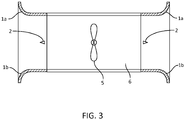
- Figure 3 shows a pair of ionisers, similar to the ones shown in figures 1 and 2 , which flank a centrally disposed fan (5) and which is housed in housing 6.
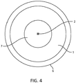
- Figure 4 shows a device according to figures 1 , 2 and 3 seen along the cone axis view.
- the air intake wall (1) for guiding air into the ioniser from ambient and also to act as receiving electrode for the corona discharge emitting electrode, an outer rim (6) which defines the outer edge of the intake wall (1), and the central intake aperture through which is the ambient air is forced towards a filter mechanism.
- Figure 5 shows a pair of opposing air intake walls which are curved in a fashion which narrows the air intake cross section as ambient air enters the ioniser.
- the corona discharge device comprises a series of opposing pins (8).
- the corona discharge device is a wire (2).
- figure 7 is shown the same device illustrated in Figure 5 but in perspective.
Landscapes
- Physics & Mathematics (AREA)
- Engineering & Computer Science (AREA)
- Plasma & Fusion (AREA)
- Air-Conditioning For Vehicles (AREA)
- Disinfection, Sterilisation Or Deodorisation Of Air (AREA)
Priority Applications (3)
| Application Number | Priority Date | Filing Date | Title |
|---|---|---|---|
| EP18213948.5A EP3671983A1 (de) | 2018-12-19 | 2018-12-19 | Ionisator |
| EP19801927.5A EP3884551A1 (de) | 2018-11-19 | 2019-11-19 | Ionisierungseinheit zum negativen laden von in einem luftstrom vorhandenen schwebeteilchen, luftreinigungsvorrichtung und an ein fahrzeug angepasste vorrichtung |
| PCT/EP2019/081856 WO2020104488A1 (en) | 2018-11-19 | 2019-11-19 | An ionizing unit for negatively charging airborne particles present in an airflow, an air-purifying device and a vehicle-adapted device |
Applications Claiming Priority (1)
| Application Number | Priority Date | Filing Date | Title |
|---|---|---|---|
| EP18213948.5A EP3671983A1 (de) | 2018-12-19 | 2018-12-19 | Ionisator |
Publications (1)
| Publication Number | Publication Date |
|---|---|
| EP3671983A1 true EP3671983A1 (de) | 2020-06-24 |
Family
ID=64746111
Family Applications (1)
| Application Number | Title | Priority Date | Filing Date |
|---|---|---|---|
| EP18213948.5A Withdrawn EP3671983A1 (de) | 2018-11-19 | 2018-12-19 | Ionisator |
Country Status (1)
| Country | Link |
|---|---|
| EP (1) | EP3671983A1 (de) |
Citations (4)
| Publication number | Priority date | Publication date | Assignee | Title |
|---|---|---|---|---|
| US4247307A (en) * | 1979-09-21 | 1981-01-27 | Union Carbide Corporation | High intensity ionization-wet collection method and apparatus |
| US20040191134A1 (en) * | 1998-11-05 | 2004-09-30 | Sharper Image Corporation | Air conditioner devices |
| WO2014102258A1 (fr) * | 2012-12-28 | 2014-07-03 | Centre National De La Recherche Scientifique (Cnrs) | Chargeur d'aérosol concentrique par décharge électrique |
| WO2016111211A1 (ja) * | 2015-01-06 | 2016-07-14 | 株式会社 片野工業 | イオン・オゾン風発生装置及び方法 |
-
2018
- 2018-12-19 EP EP18213948.5A patent/EP3671983A1/de not_active Withdrawn
Patent Citations (4)
| Publication number | Priority date | Publication date | Assignee | Title |
|---|---|---|---|---|
| US4247307A (en) * | 1979-09-21 | 1981-01-27 | Union Carbide Corporation | High intensity ionization-wet collection method and apparatus |
| US20040191134A1 (en) * | 1998-11-05 | 2004-09-30 | Sharper Image Corporation | Air conditioner devices |
| WO2014102258A1 (fr) * | 2012-12-28 | 2014-07-03 | Centre National De La Recherche Scientifique (Cnrs) | Chargeur d'aérosol concentrique par décharge électrique |
| WO2016111211A1 (ja) * | 2015-01-06 | 2016-07-14 | 株式会社 片野工業 | イオン・オゾン風発生装置及び方法 |
Similar Documents
| Publication | Publication Date | Title |
|---|---|---|
| KR101678237B1 (ko) | 공기 정화 장치 | |
| JP6742804B2 (ja) | エアークリーニング装置 | |
| JP6783499B2 (ja) | イオン化手段を備えた空気清浄装置 | |
| CN101842164B (zh) | 空气处理装置 | |
| JP5304096B2 (ja) | 荷電装置及び空気処理装置 | |
| HU207616B (en) | Arrangement for delivering air | |
| EP3769383B1 (de) | Ionisierungsanordnung | |
| CN107635667A (zh) | 用于室内空气的净化的装置 | |
| WO2013105379A1 (ja) | 空気調和装置 | |
| US20180272357A1 (en) | Ion filtration air cleaner | |
| US20170354979A1 (en) | Electrostatic air cleaner | |
| US20230140445A1 (en) | Electrostatic separator | |
| US11117138B2 (en) | Systems and methods for gas cleaning using electrostatic precipitation and photoionization | |
| EP3713676B1 (de) | Ladevorrichtung und abscheider | |
| US20080314251A1 (en) | Discharge Device and Air Purification Device | |
| WO2017174773A1 (en) | An exhaust hood comprising an ion guide | |
| US11331678B2 (en) | Charging apparatus and precipitator | |
| JP2017131875A (ja) | 電気集塵装置 | |
| CN211914186U (zh) | 用于从空气流中分离空气传播粒子的空气净化设备 | |
| EP3654465A1 (de) | Ionisator | |
| CN211914183U (zh) | 用于从空气流中分离空气传播粒子的空气净化设备 | |
| KR102617752B1 (ko) | 한정된 공간에서 공기를 처리하기 적합한 공기 처리 장치 | |
| JP2010110692A (ja) | 荷電装置及び空気処理装置 | |
| CN211914184U (zh) | 用于从空气流中分离空气传播粒子的空气净化设备 | |
| JP4492286B2 (ja) | 排気浄化装置 |
Legal Events
| Date | Code | Title | Description |
|---|---|---|---|
| PUAI | Public reference made under article 153(3) epc to a published international application that has entered the european phase |
Free format text: ORIGINAL CODE: 0009012 |
|
| STAA | Information on the status of an ep patent application or granted ep patent |
Free format text: STATUS: THE APPLICATION HAS BEEN PUBLISHED |
|
| AK | Designated contracting states |
Kind code of ref document: A1 Designated state(s): AL AT BE BG CH CY CZ DE DK EE ES FI FR GB GR HR HU IE IS IT LI LT LU LV MC MK MT NL NO PL PT RO RS SE SI SK SM TR |
|
| AX | Request for extension of the european patent |
Extension state: BA ME |
|
| STAA | Information on the status of an ep patent application or granted ep patent |
Free format text: STATUS: THE APPLICATION IS DEEMED TO BE WITHDRAWN |
|
| 18D | Application deemed to be withdrawn |
Effective date: 20210112 |