EP3671987A1 - Ausziehbare schaltanlage mit motorisiertem einzugsmodul - Google Patents
Ausziehbare schaltanlage mit motorisiertem einzugsmodul Download PDFInfo
- Publication number
- EP3671987A1 EP3671987A1 EP18214019.4A EP18214019A EP3671987A1 EP 3671987 A1 EP3671987 A1 EP 3671987A1 EP 18214019 A EP18214019 A EP 18214019A EP 3671987 A1 EP3671987 A1 EP 3671987A1
- Authority
- EP
- European Patent Office
- Prior art keywords
- switchgear
- control gear
- compartment
- feeder module
- circuit breaker
- Prior art date
- Legal status (The legal status is an assumption and is not a legal conclusion. Google has not performed a legal analysis and makes no representation as to the accuracy of the status listed.)
- Granted
Links
Images

Classifications
-
- H—ELECTRICITY
- H02—GENERATION; CONVERSION OR DISTRIBUTION OF ELECTRIC POWER
- H02B—BOARDS, SUBSTATIONS OR SWITCHING ARRANGEMENTS FOR THE SUPPLY OR DISTRIBUTION OF ELECTRIC POWER
- H02B11/00—Switchgear having carriage withdrawable for isolation
- H02B11/12—Switchgear having carriage withdrawable for isolation with isolation by horizontal withdrawal
-
- H—ELECTRICITY
- H02—GENERATION; CONVERSION OR DISTRIBUTION OF ELECTRIC POWER
- H02B—BOARDS, SUBSTATIONS OR SWITCHING ARRANGEMENTS FOR THE SUPPLY OR DISTRIBUTION OF ELECTRIC POWER
- H02B11/00—Switchgear having carriage withdrawable for isolation
- H02B11/12—Switchgear having carriage withdrawable for isolation with isolation by horizontal withdrawal
- H02B11/167—Switchgear having carriage withdrawable for isolation with isolation by horizontal withdrawal truck type
-
- H—ELECTRICITY
- H02—GENERATION; CONVERSION OR DISTRIBUTION OF ELECTRIC POWER
- H02B—BOARDS, SUBSTATIONS OR SWITCHING ARRANGEMENTS FOR THE SUPPLY OR DISTRIBUTION OF ELECTRIC POWER
- H02B13/00—Arrangement of switchgear in which switches are enclosed in, or structurally associated with, a casing, e.g. cubicle
- H02B13/02—Arrangement of switchgear in which switches are enclosed in, or structurally associated with, a casing, e.g. cubicle with metal casing
-
- H—ELECTRICITY
- H02—GENERATION; CONVERSION OR DISTRIBUTION OF ELECTRIC POWER
- H02B—BOARDS, SUBSTATIONS OR SWITCHING ARRANGEMENTS FOR THE SUPPLY OR DISTRIBUTION OF ELECTRIC POWER
- H02B3/00—Apparatus specially adapted for the manufacture, assembly, or maintenance of boards or switchgear
Definitions
- the present invention relates to switchgear or control gear for low voltage, medium voltage or high voltage use with a substation.
- Autonomous substations or switchgear/control gear (or controlgear) systems require a robotic system for the whole substation in order to achieve a required level of autonomy.
- US 2017/0085064 A1 describes local equipment room (LER) for use in an industrial facility, having one or more robots to perform certain tasks, and LER being filled with non-atmospheric fluid or gas.
- Such robotic systems operate with the substation or switchgear or control gear and perform both monitoring and maintenance tasks.
- Such robotic system can be quite complex and expensive, especially when considering variability existing in substations today.
- robotic system can reduce maintenance tasks in a substation with respect to switchgear or control gear, the robot itself may require considerable maintenance. This can require the robot to be removed from the substation, switchgear or control gear or the personnel entering the substation, switchgear or control gear and thus leads to substation shut down.
- a switchgear or control gear comprising:
- the plurality of main switchgear or control gear components comprises a main busbar system, a circuit breaker, and at least a first part of a cable connection.
- the plurality of main switchgear or control gear components are configured to be housed in the at least one first compartment.
- the plurality of auxiliary switchgear or control gear components are configured to be housed in the second compartment.
- One or more of the at least one sensor is configured to be located in the at least one first compartment.
- the at least one sensor is configured to monitor the components in the at least one first compartment.
- the circuit breaker is associated with the feeder module.
- the feeder module is configured to be removed from the switchgear or control gear. Removal of the feeder module is configured to remove the circuit breaker from the switchgear or control gear.
- the main drive is configured to move the feeder module to remove the feeder module from the switchgear or control gear.
- the plurality of main switchgear or control gear components comprises a current transformer or sensor.
- the main drive is configured to move the feeder module to remove the feeder module from the switchgear or control gear on the basis of sensor data acquired by one or more sensor of the at least one sensor.
- one or more of the plurality of main switchgear or control gear components in addition to the circuit breaker is associated with the feeder module. Removal of the feeder module is configured to remove the one or more of the plurality of main switchgear or control gear components in addition to the circuit breaker from the switchgear or control gear.
- the second compartment is associated with the feeder module, and removal of the feeder module is configured to remove the second compartment from the switchgear or control gear.
- removal of the second compartment from the switchgear or control gear is configured to remove the plurality of auxiliary switchgear or control gear components from the switchgear or control gear.
- one or more of the at least one sensor is associated with the feeder module, and removal of the feeder module is configured to remove the one or more of the at least one sensor from the switchgear or control gear.
- one or more of the at least one sensor is located in the second compartment.
- the main drive or a secondary drive is configured to rack the circuit breaker between connected, disconnected and earthed positions.
- the main drive or secondary drive is configured to rack the circuit breaker from the connected position to the disconnected position, and then rack the circuit breaker from the disconnected position to the earthed position prior to movement of the feeder module by the main drive to remove the feeder module from the switchgear or control gear.
- the main drive when the feeder module is removed from the switchgear or control gear, the main drive is configured to move the feeder module or a new module to insert the feeder module or new feeder module into the switchgear or control gear.
- the circuit breaker or a new circuit breaker is associated with the new module, and insertion of the feeder module or new module into the switchgear or control gear is configured to insert the circuit breaker or new circuit breaker into the switchgear or control gear.
- the main drive or secondary drive is configured to rack the circuit breaker or new circuit breaker from an earthed position to a disconnected position, and then rack the circuit breaker from the disconnected position to a connected position after the movement of the feeder module or new module by the main drive to insert the feeder module or new module in the switchgear or control gear.
- the main drive is internal to or embedded in the feeder module.
- the main drive is external to the feeder module.
- the main drive comprises a floor moving system.
- the main drive is configured to move a dummy module equipped with a primary drive to insert the dummy module into the switchgear or control gear.
- the at least one first compartment comprises a plurality of first compartments.
- One compartment of the plurality of first compartments is a cable connection compartment within which is housed a second part of the cable connection and a voltage sensor and a current sensor.
- the circuit breaker is configured to be housed in a first compartment other than the cable connection compartment.
- the plurality of auxiliary switchgear or control gear components comprises a circuit breaker drive.
- the at least one first compartment is arc proof.
- At least one compartment of the at least one first compartment is open-sided.
- At least one compartment comprises at least one door or removable wall section.
- the switchgear or control gear is provided with one or more interlocks. The one or more interlocks are configured to prevent an incorrect sequence of operation and configured to prevent unauthorized access to one or more compartments of the switchgear or control gear.
- the one or more interlocks are configured to provide mechanical interlocking by moveable mechanical parts.
- the one or more interlocks are configured to be provided with sensor data from the at least one sensor.
- the one or more interlocks are configured to operate on the basis of visual data.
- one or more walls of the compartments of the switchgear or control gear are metallic.
- the metallic walls are configured to provide inner housing segregation in order to achieve the required service continuity level.
- a switchgear or control gear comprising:
- the plurality of main switchgear or control gear components comprises a main busbar system, a circuit breaker, and at least a first part of a cable connection.
- the plurality of main switchgear or control gear components are configured to be housed in the at least one first compartment in proximity to at least one wall of an outer housing of the at least one first compartment.
- the plurality of auxiliary switchgear or control components are configured to be housed in the second compartment.
- One or more of the at least one sensor is configured to be located in the at least one first compartment, and wherein the at least one sensor is configured to monitor the components in the at least one first compartment.
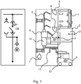
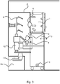
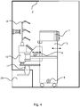
- Figs. 1-4 show examples of a switchgear or control gear for operation in a low voltage, medium voltage or high voltage substation.
- the switchgear or control gear (also known as controlgear) comprises at least one first compartment 2, 2a, a second compartment 1, a feeder module 3, a main drive 5, a plurality of main switchgear or control gear components, a plurality of auxiliary switchgear or control gear components, and at least one sensor 6, 7.
- the plurality of main switchgear or control gear components comprises a main busbar system 8, a circuit breaker 10, and at least a first part of a cable connection 11.
- the plurality of main switchgear or control gear components are configured to be housed in the at least one first compartment.
- the plurality of auxiliary switchgear or control gear components are configured to be housed in the second compartment.
- One or more of the at least one sensor is configured to be located in the at least one first compartment.
- the at least one sensor is configured to monitor the components in the at least one first compartment.
- the circuit breaker is associated with the feeder module. This association means that the circuit breaker can be moved out of the switchgear or control gear through movement of the feeder module, as discussed in more detail below.
- the feeder module is configured to be removed from the switchgear or control gear. Removal of the feeder module is configured to remove the circuit breaker from the switchgear or control gear.
- the main drive is configured to move the feeder module to remove the feeder module from the switchgear or control gear.
- the plurality of main switchgear or control gear components comprises a current transformer or sensor 9.
- the main drive is configured to move the feeder module to remove the feeder module from the switchgear or control gear on the basis of sensor data acquired by one or more sensor of the at least one sensor.
- one or more of the plurality of main switchgear or control gear components in addition to the circuit breaker is associated with the feeder module. Removal of the feeder module is configured to remove the one or more of the plurality of main switchgear or control gear components in addition to the circuit breaker from the switchgear or control gear.
- the current transformer or sensor 9 in addition to the circuit breaker 10 can be easily removed from the switchgear or control gear.
- the second compartment is associated with the feeder module. Removal of the feeder module is configured to remove the second compartment from the switchgear or control gear.
- removal of the second compartment from the switchgear or control gear is configured to remove the plurality of auxiliary switchgear or control gear components from the switchgear or control gear.
- one or more of the at least one sensor is associated with the feeder module. Removal of the feeder module is configured to remove the one or more of the at least one sensor from the switchgear or control gear.
- one or more of the at least one sensor is located in the second compartment.
- the main drive or a secondary drive 4 is configured to rack the circuit breaker between connected, disconnected and earthed positions.
- the main drive or secondary drive is configured to rack the circuit breaker from the connected position to the disconnected position, and then rack the circuit breaker from the disconnected position to the earthed position. This is done prior to movement of the feeder module by the main drive to remove the feeder module from the switchgear or control gear.
- the main drive is configured to move the feeder module or a new module to insert the feeder module or new feeder module into the switchgear or control gear.
- the circuit breaker or a new circuit breaker is associated with the new module. Insertion of the feeder module or new module into the switchgear or control gear is configured to insert the circuit breaker or new circuit breaker into the switchgear or control gear.
- the main drive or secondary drive is configured to rack the circuit breaker or new circuit breaker from an earthed position to a disconnected position, and then rack the circuit breaker from the disconnected position to a connected position. This is done after the movement of the feeder module or new module by the main drive to insert the feeder module or new module in the switchgear or control gear.
- the main drive is internal to or embedded in the feeder module.
- the main drive is external to the feeder module.
- the main drive comprises a floor moving system.
- the main drive is configured to move a dummy module equipped with a primary drive to insert the dummy module into the switchgear or control gear.
- the at least one first compartment comprises a plurality of first compartments 2, 2a.
- One compartment of the plurality of first compartments is a cable connection compartment 2a within which is housed a second part of the cable connection and a voltage sensor and a current sensor.
- the circuit breaker is configured to be housed in a first compartment 2 other than the cable connection compartment.
- the plurality of auxiliary switchgear or control gear components comprises a circuit breaker drive 10).
- the at least one first compartment is arc proof.
- At least one compartment of the at least one first compartment is open-sided.
- At least one compartment comprises at least one door or removable wall section.
- the switchgear or control gear is provided with one or more interlocks.
- the one or more interlocks are configured to prevent an incorrect sequence of operation and configured to prevent unauthorized access to one or more compartments of the switchgear or control gear.
- the one or more interlocks are configured to provide mechanical interlocking by moveable mechanical parts.
- the one or more interlocks are configured to be provided with sensor data from the at least one sensor.
- the one or more interlocks are configured to operate on the basis of visual data.
- one or more walls of the compartments of the switchgear or control gear are metallic.
- the metallic walls are configured to provide inner housing segregation in order to achieve the required service continuity level.
- the switchgear or control gear (also known as controlgear) comprises at least one first compartment 2, 2a, a second compartment 1, a plurality of main switchgear or control gear components, a plurality of auxiliary switchgear or control gear components, and at least one sensor 6, 7.
- the plurality of main switchgear or control gear components comprises a main busbar system 8, a current transformer or sensor 9, a circuit breaker 10, and at least a first part of a cable connection 11.
- the plurality of main switchgear or control gear components are configured to be housed in the at least one first compartment in proximity to at least one wall of an outer housing of the at least one first compartment.
- the plurality of auxiliary switchgear or control gear components are configured to be housed in the second compartment.
- One or more of the at least one sensor is configured to be located in the at least one first compartment.
- the at least one sensor is configured to monitor the components in the at least one first compartment.
- the plurality of main switchgear or control gear components comprises a current transformer or sensor 9.
- one or more of the at least one sensor is located in the second compartment.
- the at least one first compartment comprises a plurality of first compartments 2, 2a.
- One compartment of the plurality of first compartments is a cable connection compartment 2a within which is housed a second part of the cable connection and a voltage sensor and a current sensor.
- the circuit breaker is configured to be housed in a first compartment 2 other than the cable connection compartment.
- the plurality of auxiliary switchgear or control gear components comprises a circuit breaker drive 10.
- the at least one first compartment is arc proof.
- At least one compartment of the at least one first compartment is open-sided.
- At least one compartment comprises at least one door or removable wall section.
- the switchgear or control gear is provided with one or more interlocks, wherein the one or more interlocks are configured to prevent an incorrect sequence of operation and configured to prevent unauthorized access to one or more compartments of the switchgear or control gear.
- the one or more interlocks are configured to provide mechanical interlocking by moveable mechanical parts.
- the one or more interlocks are configured to be provided with sensor data from the at least one sensor.
- the one or more interlocks are configured to operate on the basis of visual data.
- one or more walls of the compartments of the switchgear or control gear are metallic.
- the metallic walls are configured to provide inner housing segregation in order to achieve the required service continuity level.
- a new substation development is provided that enables autonomous operation, i.e. with minimum personnel interaction required within an internal space of the substation. This is provided through remote control motorized operation for key components to allow for their operational status transitions or removal from a switchgear or control gear or provided through appropriate location of those key components, and provided together with a sensor based monitoring system.
- a non-robotic solution for a substation is provided, which can be used either on a whole substation or on some of its parts.
- Fig. 1 shows a detailed example of a switchgear or control gear, where for ease of reference the following features shown are listed:
- the substation layout in terms of the switchgear or control gear has been changed, with appropriate placement of sensors such that they can see and/or monitor or point of interest required for proper monitoring of the components of the substation/switchgear/control gear.
- a robotic system that is required to move around with sensors is not required.
- the sensors in the current solution are fixed in position.
- a withdrawable feeder module that is specific for each feeder from the main node of the main busbars.
- main drive and secondary drive can be one common drive performing both the tasks.
- Fig. 2 shows the different operating statuses for the system described here.
- the circuit breaker of the switchgear/control gear is in a connected state.
- the main drive (or secondary drive) then racks the circuit breaker to a disconnected state as shown in the next image.
- the main drive (or secondary drive) then racks the circuit breaker to an earthed state, as shown in the next image.
- the main drive has withdrawn the feeder module along with the circuit breaker and current transformer or sensor from the switchgear/control gear.
- a dummy module equipped with primary drive only can be used.
- the withdrawn module is accessible for human maintainers while the continuous operation for the switchgear is ensured.
- the main drive responsible for withdrawing the feeder module can be internal, however the main drive can be external.
- the drive need not be embedded in the module, but can be in the form of a floor moving automation system for example.
- Fig. 3 shows a detailed example of a switchgear or control gear, where for ease of reference the following features shown are listed:
- a cable connection compartment 2a can be provided, which is segregated from the rest of the switchgear space to allow safe access to cable connections for the human operators, whilst the switchgear is in operation. Access to the cable connection compartment 2a is via a removable panel or one or more doors shown in the bottom left-hand corner of Fig. 3 . Also as shown, at least one of the sensors can be part of the withdrawable module in order to make replacement of the sensor more convenient in case of failure.
- the bushing in Fig.3 indicate that the current and voltage sensors can be embedded inside the bushing. However, the current and voltage sensors can be kept as stand alone devices located in the cable compartment.
- Fig. 4 shows a detailed example of a switchgear or control gear, where for ease of reference the following features shown are listed:
- the low-voltage compartment 1 can be part of the withdrawable feeder module, enabling the auxiliary components to be easily maintained.
- at least one of the sensors can be part of the low-voltage compartment but still monitoring the arc proof enclosure and the components contained therein, but also enabling this sensor to be easily replaced if necessary.
- the switchgear/control gear can be designed as unmanned by removing part of the arc proof enclosure allowing automation system to perform the condition monitoring instead of fixed sensors. Thus, in such a situation a part of the enclosure, for example that shown in a thin line in Fig. 4 , can be removed.
- the at least one sensor 6, 7 can include at least one camera, linked to an image recognition system.
- the image recognition system is configured to evaluate actual images with adaptive image data, in order to be able to locate and to analyse physical reasons for faults or deterioration of components that might lead to faults.
- the camera is provided with a video mode.
- the image recognition system is configured to automatically the slow motion video sequences with regular expected function sequences through comparison of the slow motion video sequences from an adaptive data field, which show the expected regular function.
- the at least one sensor 6, 7 can include a temperature sensing system and/or a temperature recognition system.
- the at least one sensor 6, 7 can include an environmental sensing system configured to sense humidity, moisture or pressure, linked to an environment recognition system.
- the at least one sensor 6, 7 can include a surface contamination sensing system and/or a surface contamination recognition system that can utilize other sensed quantities.
- the at least one sensor 6, 7 can include an electrical discharge sensing system and/or an electrical discharge recognition system that can utilize other sensed quantities.
- the at least one sensor 6, 7 is configured to communicate via a data network or an external data communication interface.
- the main switchgear or control gear components can also comprises one or more of: an earthing switch, voltage indication, surge arrestor, UFES, IS-limitor, contactor, load-break switch, and fuse.
Landscapes
- Engineering & Computer Science (AREA)
- Power Engineering (AREA)
- Patch Boards (AREA)
Priority Applications (1)
| Application Number | Priority Date | Filing Date | Title |
|---|---|---|---|
| EP18214019.4A EP3671987B1 (de) | 2018-12-19 | 2018-12-19 | Schaltanlage mit ausziehbarem einzugsmodul |
Applications Claiming Priority (1)
| Application Number | Priority Date | Filing Date | Title |
|---|---|---|---|
| EP18214019.4A EP3671987B1 (de) | 2018-12-19 | 2018-12-19 | Schaltanlage mit ausziehbarem einzugsmodul |
Publications (2)
| Publication Number | Publication Date |
|---|---|
| EP3671987A1 true EP3671987A1 (de) | 2020-06-24 |
| EP3671987B1 EP3671987B1 (de) | 2023-09-06 |
Family
ID=64746155
Family Applications (1)
| Application Number | Title | Priority Date | Filing Date |
|---|---|---|---|
| EP18214019.4A Active EP3671987B1 (de) | 2018-12-19 | 2018-12-19 | Schaltanlage mit ausziehbarem einzugsmodul |
Country Status (1)
| Country | Link |
|---|---|
| EP (1) | EP3671987B1 (de) |
Citations (5)
| Publication number | Priority date | Publication date | Assignee | Title |
|---|---|---|---|---|
| DE10120237A1 (de) * | 2001-04-19 | 2002-10-24 | Siemens Ag | Wartungseinrichtung für eine Schaltanlage |
| RU2011138768A (ru) * | 2011-09-21 | 2012-02-10 | Общество с ограниченной ответственностью "ВостокЭнергоКомплект" (RU) | Высоковольтное комплектное распределительное устройство |
| CN102916362A (zh) * | 2011-08-02 | 2013-02-06 | 湖南丰日电源电气股份有限公司 | 一种地铁用智能型充气式高压真空开关柜 |
| WO2013084572A1 (ja) * | 2011-12-08 | 2013-06-13 | 三菱電機株式会社 | スイッチギヤ |
| US20170085064A1 (en) | 2015-09-18 | 2017-03-23 | Brandon Cassimere | Local Electrical/Instrumentation Room |
Family Cites Families (1)
| Publication number | Priority date | Publication date | Assignee | Title |
|---|---|---|---|---|
| CN200944508Y (zh) * | 2006-09-11 | 2007-09-05 | 耐吉科技股份有限公司 | 一种手车式高压开关柜 |
-
2018
- 2018-12-19 EP EP18214019.4A patent/EP3671987B1/de active Active
Patent Citations (5)
| Publication number | Priority date | Publication date | Assignee | Title |
|---|---|---|---|---|
| DE10120237A1 (de) * | 2001-04-19 | 2002-10-24 | Siemens Ag | Wartungseinrichtung für eine Schaltanlage |
| CN102916362A (zh) * | 2011-08-02 | 2013-02-06 | 湖南丰日电源电气股份有限公司 | 一种地铁用智能型充气式高压真空开关柜 |
| RU2011138768A (ru) * | 2011-09-21 | 2012-02-10 | Общество с ограниченной ответственностью "ВостокЭнергоКомплект" (RU) | Высоковольтное комплектное распределительное устройство |
| WO2013084572A1 (ja) * | 2011-12-08 | 2013-06-13 | 三菱電機株式会社 | スイッチギヤ |
| US20170085064A1 (en) | 2015-09-18 | 2017-03-23 | Brandon Cassimere | Local Electrical/Instrumentation Room |
Non-Patent Citations (1)
| Title |
|---|
| SCHNEIDER: "Air Insulated Switchgear up to 24 kV Medium Voltage Distribution Catalogue I 2015", 23 March 2015 (2015-03-23), pages 1 - 108, XP055585757, Retrieved from the Internet <URL:http://77.221.237.111/flipbooks/PIX_MCSet_Katalog_2015/content/PIX_MCSet_Katalog_2015.pdf> [retrieved on 20190506] * |
Also Published As
| Publication number | Publication date |
|---|---|
| EP3671987B1 (de) | 2023-09-06 |
Similar Documents
| Publication | Publication Date | Title |
|---|---|---|
| US11715937B2 (en) | Switchgear or control gear | |
| CN110832719B (zh) | 一种无人操作和维护的室内开关设备装置 | |
| US11682885B2 (en) | Switchgear | |
| US11511428B2 (en) | Switchgear or controlgear with unmanned operation and maintenance, and method of operating the same | |
| CN110770988B (zh) | 包含无人操作和维护的开关装置或控制装置的变电站 | |
| US11637414B2 (en) | Three phase switchgear using single phase equipment in single casing | |
| KR101008956B1 (ko) | 계통설비별 색상정보를 이용한 변전소 모니터링 시스템 | |
| CN111342385B (zh) | 开关装置或控制装置 | |
| EP3671987B1 (de) | Schaltanlage mit ausziehbarem einzugsmodul | |
| CN109494600A (zh) | 支架及包括其的高压开关柜 | |
| US8446709B2 (en) | Electrical system and automatic identification system therefor | |
| US11670919B2 (en) | Three phase switchgear or control gear | |
| Bowen et al. | Future trends in electrical substations from the end-users perspective-Near future safety features | |
| CN118872169A (zh) | 可扩展的电力分接系统 | |
| Bode | Switchgear for 2000 and beyond |
Legal Events
| Date | Code | Title | Description |
|---|---|---|---|
| PUAI | Public reference made under article 153(3) epc to a published international application that has entered the european phase |
Free format text: ORIGINAL CODE: 0009012 |
|
| STAA | Information on the status of an ep patent application or granted ep patent |
Free format text: STATUS: THE APPLICATION HAS BEEN PUBLISHED |
|
| AK | Designated contracting states |
Kind code of ref document: A1 Designated state(s): AL AT BE BG CH CY CZ DE DK EE ES FI FR GB GR HR HU IE IS IT LI LT LU LV MC MK MT NL NO PL PT RO RS SE SI SK SM TR |
|
| AX | Request for extension of the european patent |
Extension state: BA ME |
|
| STAA | Information on the status of an ep patent application or granted ep patent |
Free format text: STATUS: REQUEST FOR EXAMINATION WAS MADE |
|
| 17P | Request for examination filed |
Effective date: 20201209 |
|
| RBV | Designated contracting states (corrected) |
Designated state(s): AL AT BE BG CH CY CZ DE DK EE ES FI FR GB GR HR HU IE IS IT LI LT LU LV MC MK MT NL NO PL PT RO RS SE SI SK SM TR |
|
| STAA | Information on the status of an ep patent application or granted ep patent |
Free format text: STATUS: EXAMINATION IS IN PROGRESS |
|
| 17Q | First examination report despatched |
Effective date: 20210804 |
|
| GRAP | Despatch of communication of intention to grant a patent |
Free format text: ORIGINAL CODE: EPIDOSNIGR1 |
|
| STAA | Information on the status of an ep patent application or granted ep patent |
Free format text: STATUS: GRANT OF PATENT IS INTENDED |
|
| INTG | Intention to grant announced |
Effective date: 20230413 |
|
| GRAS | Grant fee paid |
Free format text: ORIGINAL CODE: EPIDOSNIGR3 |
|
| GRAA | (expected) grant |
Free format text: ORIGINAL CODE: 0009210 |
|
| STAA | Information on the status of an ep patent application or granted ep patent |
Free format text: STATUS: THE PATENT HAS BEEN GRANTED |
|
| AK | Designated contracting states |
Kind code of ref document: B1 Designated state(s): AL AT BE BG CH CY CZ DE DK EE ES FI FR GB GR HR HU IE IS IT LI LT LU LV MC MK MT NL NO PL PT RO RS SE SI SK SM TR |
|
| RAP3 | Party data changed (applicant data changed or rights of an application transferred) |
Owner name: ABB SCHWEIZ AG |
|
| REG | Reference to a national code |
Ref country code: GB Ref legal event code: FG4D |
|
| REG | Reference to a national code |
Ref country code: CH Ref legal event code: EP |
|
| REG | Reference to a national code |
Ref country code: IE Ref legal event code: FG4D |
|
| REG | Reference to a national code |
Ref country code: DE Ref legal event code: R096 Ref document number: 602018056899 Country of ref document: DE |
|
| REG | Reference to a national code |
Ref country code: LT Ref legal event code: MG9D |
|
| REG | Reference to a national code |
Ref country code: NL Ref legal event code: MP Effective date: 20230906 |
|
| PG25 | Lapsed in a contracting state [announced via postgrant information from national office to epo] |
Ref country code: GR Free format text: LAPSE BECAUSE OF FAILURE TO SUBMIT A TRANSLATION OF THE DESCRIPTION OR TO PAY THE FEE WITHIN THE PRESCRIBED TIME-LIMIT Effective date: 20231207 |
|
| PG25 | Lapsed in a contracting state [announced via postgrant information from national office to epo] |
Ref country code: SE Free format text: LAPSE BECAUSE OF FAILURE TO SUBMIT A TRANSLATION OF THE DESCRIPTION OR TO PAY THE FEE WITHIN THE PRESCRIBED TIME-LIMIT Effective date: 20230906 Ref country code: RS Free format text: LAPSE BECAUSE OF FAILURE TO SUBMIT A TRANSLATION OF THE DESCRIPTION OR TO PAY THE FEE WITHIN THE PRESCRIBED TIME-LIMIT Effective date: 20230906 Ref country code: NO Free format text: LAPSE BECAUSE OF FAILURE TO SUBMIT A TRANSLATION OF THE DESCRIPTION OR TO PAY THE FEE WITHIN THE PRESCRIBED TIME-LIMIT Effective date: 20231206 Ref country code: LV Free format text: LAPSE BECAUSE OF FAILURE TO SUBMIT A TRANSLATION OF THE DESCRIPTION OR TO PAY THE FEE WITHIN THE PRESCRIBED TIME-LIMIT Effective date: 20230906 Ref country code: LT Free format text: LAPSE BECAUSE OF FAILURE TO SUBMIT A TRANSLATION OF THE DESCRIPTION OR TO PAY THE FEE WITHIN THE PRESCRIBED TIME-LIMIT Effective date: 20230906 Ref country code: HR Free format text: LAPSE BECAUSE OF FAILURE TO SUBMIT A TRANSLATION OF THE DESCRIPTION OR TO PAY THE FEE WITHIN THE PRESCRIBED TIME-LIMIT Effective date: 20230906 Ref country code: GR Free format text: LAPSE BECAUSE OF FAILURE TO SUBMIT A TRANSLATION OF THE DESCRIPTION OR TO PAY THE FEE WITHIN THE PRESCRIBED TIME-LIMIT Effective date: 20231207 Ref country code: FI Free format text: LAPSE BECAUSE OF FAILURE TO SUBMIT A TRANSLATION OF THE DESCRIPTION OR TO PAY THE FEE WITHIN THE PRESCRIBED TIME-LIMIT Effective date: 20230906 |
|
| REG | Reference to a national code |
Ref country code: AT Ref legal event code: MK05 Ref document number: 1609789 Country of ref document: AT Kind code of ref document: T Effective date: 20230906 |
|
| PG25 | Lapsed in a contracting state [announced via postgrant information from national office to epo] |
Ref country code: NL Free format text: LAPSE BECAUSE OF FAILURE TO SUBMIT A TRANSLATION OF THE DESCRIPTION OR TO PAY THE FEE WITHIN THE PRESCRIBED TIME-LIMIT Effective date: 20230906 |
|
| PG25 | Lapsed in a contracting state [announced via postgrant information from national office to epo] |
Ref country code: IS Free format text: LAPSE BECAUSE OF FAILURE TO SUBMIT A TRANSLATION OF THE DESCRIPTION OR TO PAY THE FEE WITHIN THE PRESCRIBED TIME-LIMIT Effective date: 20240106 |
|
| PG25 | Lapsed in a contracting state [announced via postgrant information from national office to epo] |
Ref country code: AT Free format text: LAPSE BECAUSE OF FAILURE TO SUBMIT A TRANSLATION OF THE DESCRIPTION OR TO PAY THE FEE WITHIN THE PRESCRIBED TIME-LIMIT Effective date: 20230906 |
|
| PG25 | Lapsed in a contracting state [announced via postgrant information from national office to epo] |
Ref country code: ES Free format text: LAPSE BECAUSE OF FAILURE TO SUBMIT A TRANSLATION OF THE DESCRIPTION OR TO PAY THE FEE WITHIN THE PRESCRIBED TIME-LIMIT Effective date: 20230906 |
|
| PG25 | Lapsed in a contracting state [announced via postgrant information from national office to epo] |
Ref country code: SM Free format text: LAPSE BECAUSE OF FAILURE TO SUBMIT A TRANSLATION OF THE DESCRIPTION OR TO PAY THE FEE WITHIN THE PRESCRIBED TIME-LIMIT Effective date: 20230906 Ref country code: RO Free format text: LAPSE BECAUSE OF FAILURE TO SUBMIT A TRANSLATION OF THE DESCRIPTION OR TO PAY THE FEE WITHIN THE PRESCRIBED TIME-LIMIT Effective date: 20230906 Ref country code: IS Free format text: LAPSE BECAUSE OF FAILURE TO SUBMIT A TRANSLATION OF THE DESCRIPTION OR TO PAY THE FEE WITHIN THE PRESCRIBED TIME-LIMIT Effective date: 20240106 Ref country code: ES Free format text: LAPSE BECAUSE OF FAILURE TO SUBMIT A TRANSLATION OF THE DESCRIPTION OR TO PAY THE FEE WITHIN THE PRESCRIBED TIME-LIMIT Effective date: 20230906 Ref country code: EE Free format text: LAPSE BECAUSE OF FAILURE TO SUBMIT A TRANSLATION OF THE DESCRIPTION OR TO PAY THE FEE WITHIN THE PRESCRIBED TIME-LIMIT Effective date: 20230906 Ref country code: CZ Free format text: LAPSE BECAUSE OF FAILURE TO SUBMIT A TRANSLATION OF THE DESCRIPTION OR TO PAY THE FEE WITHIN THE PRESCRIBED TIME-LIMIT Effective date: 20230906 Ref country code: AT Free format text: LAPSE BECAUSE OF FAILURE TO SUBMIT A TRANSLATION OF THE DESCRIPTION OR TO PAY THE FEE WITHIN THE PRESCRIBED TIME-LIMIT Effective date: 20230906 Ref country code: PT Free format text: LAPSE BECAUSE OF FAILURE TO SUBMIT A TRANSLATION OF THE DESCRIPTION OR TO PAY THE FEE WITHIN THE PRESCRIBED TIME-LIMIT Effective date: 20240108 Ref country code: SK Free format text: LAPSE BECAUSE OF FAILURE TO SUBMIT A TRANSLATION OF THE DESCRIPTION OR TO PAY THE FEE WITHIN THE PRESCRIBED TIME-LIMIT Effective date: 20230906 |
|
| PG25 | Lapsed in a contracting state [announced via postgrant information from national office to epo] |
Ref country code: PL Free format text: LAPSE BECAUSE OF FAILURE TO SUBMIT A TRANSLATION OF THE DESCRIPTION OR TO PAY THE FEE WITHIN THE PRESCRIBED TIME-LIMIT Effective date: 20230906 |
|
| REG | Reference to a national code |
Ref country code: DE Ref legal event code: R097 Ref document number: 602018056899 Country of ref document: DE |
|
| PG25 | Lapsed in a contracting state [announced via postgrant information from national office to epo] |
Ref country code: DK Free format text: LAPSE BECAUSE OF FAILURE TO SUBMIT A TRANSLATION OF THE DESCRIPTION OR TO PAY THE FEE WITHIN THE PRESCRIBED TIME-LIMIT Effective date: 20230906 |
|
| PLBE | No opposition filed within time limit |
Free format text: ORIGINAL CODE: 0009261 |
|
| STAA | Information on the status of an ep patent application or granted ep patent |
Free format text: STATUS: NO OPPOSITION FILED WITHIN TIME LIMIT |
|
| PG25 | Lapsed in a contracting state [announced via postgrant information from national office to epo] |
Ref country code: DK Free format text: LAPSE BECAUSE OF FAILURE TO SUBMIT A TRANSLATION OF THE DESCRIPTION OR TO PAY THE FEE WITHIN THE PRESCRIBED TIME-LIMIT Effective date: 20230906 Ref country code: SI Free format text: LAPSE BECAUSE OF FAILURE TO SUBMIT A TRANSLATION OF THE DESCRIPTION OR TO PAY THE FEE WITHIN THE PRESCRIBED TIME-LIMIT Effective date: 20230906 |
|
| REG | Reference to a national code |
Ref country code: CH Ref legal event code: PL |
|
| 26N | No opposition filed |
Effective date: 20240607 |
|
| PG25 | Lapsed in a contracting state [announced via postgrant information from national office to epo] |
Ref country code: LU Free format text: LAPSE BECAUSE OF NON-PAYMENT OF DUE FEES Effective date: 20231219 |
|
| PG25 | Lapsed in a contracting state [announced via postgrant information from national office to epo] |
Ref country code: MC Free format text: LAPSE BECAUSE OF FAILURE TO SUBMIT A TRANSLATION OF THE DESCRIPTION OR TO PAY THE FEE WITHIN THE PRESCRIBED TIME-LIMIT Effective date: 20230906 |
|
| GBPC | Gb: european patent ceased through non-payment of renewal fee |
Effective date: 20231219 |
|
| REG | Reference to a national code |
Ref country code: BE Ref legal event code: MM Effective date: 20231231 |
|
| PG25 | Lapsed in a contracting state [announced via postgrant information from national office to epo] |
Ref country code: MC Free format text: LAPSE BECAUSE OF FAILURE TO SUBMIT A TRANSLATION OF THE DESCRIPTION OR TO PAY THE FEE WITHIN THE PRESCRIBED TIME-LIMIT Effective date: 20230906 Ref country code: LU Free format text: LAPSE BECAUSE OF NON-PAYMENT OF DUE FEES Effective date: 20231219 |
|
| REG | Reference to a national code |
Ref country code: IE Ref legal event code: MM4A |
|
| PG25 | Lapsed in a contracting state [announced via postgrant information from national office to epo] |
Ref country code: IE Free format text: LAPSE BECAUSE OF NON-PAYMENT OF DUE FEES Effective date: 20231219 |
|
| PG25 | Lapsed in a contracting state [announced via postgrant information from national office to epo] |
Ref country code: GB Free format text: LAPSE BECAUSE OF NON-PAYMENT OF DUE FEES Effective date: 20231219 |
|
| PG25 | Lapsed in a contracting state [announced via postgrant information from national office to epo] |
Ref country code: BE Free format text: LAPSE BECAUSE OF NON-PAYMENT OF DUE FEES Effective date: 20231231 |
|
| PG25 | Lapsed in a contracting state [announced via postgrant information from national office to epo] |
Ref country code: CH Free format text: LAPSE BECAUSE OF NON-PAYMENT OF DUE FEES Effective date: 20231231 |
|
| PG25 | Lapsed in a contracting state [announced via postgrant information from national office to epo] |
Ref country code: IE Free format text: LAPSE BECAUSE OF NON-PAYMENT OF DUE FEES Effective date: 20231219 Ref country code: GB Free format text: LAPSE BECAUSE OF NON-PAYMENT OF DUE FEES Effective date: 20231219 Ref country code: CH Free format text: LAPSE BECAUSE OF NON-PAYMENT OF DUE FEES Effective date: 20231231 Ref country code: BE Free format text: LAPSE BECAUSE OF NON-PAYMENT OF DUE FEES Effective date: 20231231 |
|
| PG25 | Lapsed in a contracting state [announced via postgrant information from national office to epo] |
Ref country code: BG Free format text: LAPSE BECAUSE OF FAILURE TO SUBMIT A TRANSLATION OF THE DESCRIPTION OR TO PAY THE FEE WITHIN THE PRESCRIBED TIME-LIMIT Effective date: 20230906 |
|
| PG25 | Lapsed in a contracting state [announced via postgrant information from national office to epo] |
Ref country code: BG Free format text: LAPSE BECAUSE OF FAILURE TO SUBMIT A TRANSLATION OF THE DESCRIPTION OR TO PAY THE FEE WITHIN THE PRESCRIBED TIME-LIMIT Effective date: 20230906 |
|
| PG25 | Lapsed in a contracting state [announced via postgrant information from national office to epo] |
Ref country code: CY Free format text: LAPSE BECAUSE OF FAILURE TO SUBMIT A TRANSLATION OF THE DESCRIPTION OR TO PAY THE FEE WITHIN THE PRESCRIBED TIME-LIMIT; INVALID AB INITIO Effective date: 20181219 |
|
| PG25 | Lapsed in a contracting state [announced via postgrant information from national office to epo] |
Ref country code: HU Free format text: LAPSE BECAUSE OF FAILURE TO SUBMIT A TRANSLATION OF THE DESCRIPTION OR TO PAY THE FEE WITHIN THE PRESCRIBED TIME-LIMIT; INVALID AB INITIO Effective date: 20181219 |
|
| PG25 | Lapsed in a contracting state [announced via postgrant information from national office to epo] |
Ref country code: TR Free format text: LAPSE BECAUSE OF FAILURE TO SUBMIT A TRANSLATION OF THE DESCRIPTION OR TO PAY THE FEE WITHIN THE PRESCRIBED TIME-LIMIT Effective date: 20230906 |
|
| PGFP | Annual fee paid to national office [announced via postgrant information from national office to epo] |
Ref country code: DE Payment date: 20251211 Year of fee payment: 8 |
|
| PGFP | Annual fee paid to national office [announced via postgrant information from national office to epo] |
Ref country code: IT Payment date: 20251223 Year of fee payment: 8 |
|
| PGFP | Annual fee paid to national office [announced via postgrant information from national office to epo] |
Ref country code: FR Payment date: 20251229 Year of fee payment: 8 |