EP3671988A1 - Hermetischgasdichte schaltanlage mit einem einzelnes fach für leistungsschalter, trennschalter mit dreipositionen und hauptbusschiene. - Google Patents
Hermetischgasdichte schaltanlage mit einem einzelnes fach für leistungsschalter, trennschalter mit dreipositionen und hauptbusschiene. Download PDFInfo
- Publication number
- EP3671988A1 EP3671988A1 EP18213994.9A EP18213994A EP3671988A1 EP 3671988 A1 EP3671988 A1 EP 3671988A1 EP 18213994 A EP18213994 A EP 18213994A EP 3671988 A1 EP3671988 A1 EP 3671988A1
- Authority
- EP
- European Patent Office
- Prior art keywords
- compartment
- switchgear
- control gear
- components
- main
- Prior art date
- Legal status (The legal status is an assumption and is not a legal conclusion. Google has not performed a legal analysis and makes no representation as to the accuracy of the status listed.)
- Pending
Links
Images

Classifications
-
- H—ELECTRICITY
- H02—GENERATION; CONVERSION OR DISTRIBUTION OF ELECTRIC POWER
- H02B—BOARDS, SUBSTATIONS OR SWITCHING ARRANGEMENTS FOR THE SUPPLY OR DISTRIBUTION OF ELECTRIC POWER
- H02B13/00—Arrangement of switchgear in which switches are enclosed in, or structurally associated with, a casing, e.g. cubicle
- H02B13/02—Arrangement of switchgear in which switches are enclosed in, or structurally associated with, a casing, e.g. cubicle with metal casing
-
- H—ELECTRICITY
- H02—GENERATION; CONVERSION OR DISTRIBUTION OF ELECTRIC POWER
- H02B—BOARDS, SUBSTATIONS OR SWITCHING ARRANGEMENTS FOR THE SUPPLY OR DISTRIBUTION OF ELECTRIC POWER
- H02B1/00—Frameworks, boards, panels, desks, casings; Details of substations or switching arrangements
- H02B1/26—Casings; Parts thereof or accessories therefor
- H02B1/30—Cabinet-type casings; Parts thereof or accessories therefor
- H02B1/32—Mounting of devices therein
- H02B1/34—Racks
-
- H—ELECTRICITY
- H01—ELECTRIC ELEMENTS
- H01H—ELECTRIC SWITCHES; RELAYS; SELECTORS; EMERGENCY PROTECTIVE DEVICES
- H01H33/00—High-tension or heavy-current switches with arc-extinguishing or arc-preventing means
- H01H33/02—Details
- H01H33/027—Integrated apparatus for measuring current or voltage
-
- H—ELECTRICITY
- H02—GENERATION; CONVERSION OR DISTRIBUTION OF ELECTRIC POWER
- H02B—BOARDS, SUBSTATIONS OR SWITCHING ARRANGEMENTS FOR THE SUPPLY OR DISTRIBUTION OF ELECTRIC POWER
- H02B1/00—Frameworks, boards, panels, desks, casings; Details of substations or switching arrangements
- H02B1/14—Shutters or guards for preventing access to contacts
-
- H—ELECTRICITY
- H02—GENERATION; CONVERSION OR DISTRIBUTION OF ELECTRIC POWER
- H02B—BOARDS, SUBSTATIONS OR SWITCHING ARRANGEMENTS FOR THE SUPPLY OR DISTRIBUTION OF ELECTRIC POWER
- H02B1/00—Frameworks, boards, panels, desks, casings; Details of substations or switching arrangements
- H02B1/20—Bus-bar or other wiring layouts, e.g. in cubicles, in switchyards
- H02B1/202—Cable lay-outs
-
- H—ELECTRICITY
- H02—GENERATION; CONVERSION OR DISTRIBUTION OF ELECTRIC POWER
- H02B—BOARDS, SUBSTATIONS OR SWITCHING ARRANGEMENTS FOR THE SUPPLY OR DISTRIBUTION OF ELECTRIC POWER
- H02B1/00—Frameworks, boards, panels, desks, casings; Details of substations or switching arrangements
- H02B1/24—Circuit arrangements for boards or switchyards
-
- H—ELECTRICITY
- H02—GENERATION; CONVERSION OR DISTRIBUTION OF ELECTRIC POWER
- H02B—BOARDS, SUBSTATIONS OR SWITCHING ARRANGEMENTS FOR THE SUPPLY OR DISTRIBUTION OF ELECTRIC POWER
- H02B1/00—Frameworks, boards, panels, desks, casings; Details of substations or switching arrangements
- H02B1/26—Casings; Parts thereof or accessories therefor
- H02B1/30—Cabinet-type casings; Parts thereof or accessories therefor
- H02B1/38—Hinged covers or doors
-
- H—ELECTRICITY
- H02—GENERATION; CONVERSION OR DISTRIBUTION OF ELECTRIC POWER
- H02B—BOARDS, SUBSTATIONS OR SWITCHING ARRANGEMENTS FOR THE SUPPLY OR DISTRIBUTION OF ELECTRIC POWER
- H02B13/00—Arrangement of switchgear in which switches are enclosed in, or structurally associated with, a casing, e.g. cubicle
- H02B13/02—Arrangement of switchgear in which switches are enclosed in, or structurally associated with, a casing, e.g. cubicle with metal casing
- H02B13/025—Safety arrangements, e.g. in case of excessive pressure or fire due to electrical defect
-
- H—ELECTRICITY
- H02—GENERATION; CONVERSION OR DISTRIBUTION OF ELECTRIC POWER
- H02B—BOARDS, SUBSTATIONS OR SWITCHING ARRANGEMENTS FOR THE SUPPLY OR DISTRIBUTION OF ELECTRIC POWER
- H02B1/00—Frameworks, boards, panels, desks, casings; Details of substations or switching arrangements
- H02B1/26—Casings; Parts thereof or accessories therefor
- H02B1/28—Casings; Parts thereof or accessories therefor dustproof, splashproof, drip-proof, waterproof or flameproof
-
- H—ELECTRICITY
- H02—GENERATION; CONVERSION OR DISTRIBUTION OF ELECTRIC POWER
- H02B—BOARDS, SUBSTATIONS OR SWITCHING ARRANGEMENTS FOR THE SUPPLY OR DISTRIBUTION OF ELECTRIC POWER
- H02B3/00—Apparatus specially adapted for the manufacture, assembly, or maintenance of boards or switchgear
Definitions
- the present invention relates to switchgear or control gear for low voltage, medium voltage or high voltage use with a substation.
- Autonomous substations or switchgear/control gear (or controlgear) systems require a robotic system for the whole substation in order to achieve a required level of autonomy.
- US 2017/0085064 A1 describes local equipment room (LER) for use in an industrial facility, having one or more robots to perform certain tasks, and LER being filled with non-atmospheric fluid or gas.
- Such robotic systems operate with the substation or switchgear or control gear and perform both monitoring and maintenance tasks.
- Such robotic system can be quite complex and expensive, especially when considering variability existing in substations today.
- robotic system can reduce maintenance tasks in a substation with respect to switchgear or control gear, the robot itself may require considerable maintenance. This can require the robot to be removed from the substation, switchgear or control gear or the personnel entering the substation, switchgear or control gear and thus leads to substation shut down.
- a switchgear or control gear comprising:
- the plurality of main switchgear or control gear components comprises a main busbar system, a three position linear or rotational movement disconnector, a circuit breaker, and at least a first part of an insulated cable connection.
- the plurality of auxiliary switchgear or control gear components comprises a disconnector drive and a circuit breaker drive.
- the plurality of main switchgear or control gear components are housed in the at least one first compartment.
- the plurality of auxiliary switchgear or control gear components are housed in the at least one second compartment.
- the at least one first compartment is arc proof.
- the at least one first compartment complies with IP43 standards.
- the at least one first compartment complies with IP54 standards.
- the at least one first compartment is not configured to be filled with SF6 gas for operational purposes.
- the at least one first compartment is not filled with SF6 gas.
- the at least one first compartment comprises a plurality of first compartments.
- One compartment of the plurality of first compartments is a cable connection compartment within which is housed a second part of the insulated cable connection and a voltage sensor and a current sensor.
- the circuit breaker is housed in a first compartment other than the cable connection compartment.
- At least one sensor is located in the cable connection compartment.
- the at least one sensor is configured to monitor the components in the cable connection compartment,
- a second part of the insulated cable connection and a voltage sensor and a current sensor are housed in the at least one second compartment.
- At least one sensor is located in the at least one second compartment.
- the at least one sensor is configured to monitor the components in the at least one second compartment.
- the main switchgear or control gear components comprises one or more of: an earthing switch, voltage indication, surge arrestor, UFES, IS-limitor, contactor, load-break switch, and fuse.
- the at least one second compartment is open-sided.
- the at least one first compartment comprises at least one door or removable wall section.
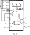
- Figs. 1-2 show examples of a switchgear or control gear for operation in a low voltage, medium voltage or high voltage substation.
- the switchgear or control gear (also known as controlgear) comprises at least one first compartment 1, 1a, at least one second compartment 8, a plurality of main switchgear or control gear components, and a plurality of auxiliary switchgear or control gear components.
- the plurality of main switchgear or control gear components comprises a main busbar system 2, a three position linear or rotational movement disconnector 3, a circuit breaker 4, and at least a first part of an insulated cable connection 5, 5a.
- the plurality of auxiliary switchgear or control gear components comprises a disconnector drive 9 and a circuit breaker drive 10.
- the plurality of main switchgear or control gear components are housed in the at least one first compartment.
- the plurality of auxiliary switchgear or control gear components are housed in the at least one second compartment.
- the at least one first compartment When one or more of the plurality of main switchgear or control gear components is energized the at least one first compartment is configured to be hermetically sealed or maintained at an internal air pressure greater than ambient air pressure.
- the plurality of main switchgear or control gear components When the plurality of main switchgear or control gear components are de-energized the at least one first compartment is configured to enable an operator to access an interior of the at least one first compartment.
- the at least one first compartment is arc proof.
- the at least one first compartment complies with IP43 standards.
- the at least one first compartment complies with IP54 standards.
- the at least one first compartment is not configured to be filled with SF6 gas for operational purposes.
- the at least one first compartment is not filled with SF6 gas.
- the at least one first compartment comprises a plurality of first compartments 1, 1a.
- One compartment of the plurality of first compartments is a cable connection compartment 1a within which is housed a second part of the insulated cable connection and a voltage sensor 12a and a current sensor 11a.
- the circuit breaker is housed in a first compartment 1 other than the cable connection compartment.
- At least one sensor 6, 7 is located in the cable connection compartment.
- the at least one sensor is configured to monitor the components in the cable connection compartment. This can be for example to monitor temperatures to detect overheating.
- the fields of view of the sensors are shown in Fig. 1 .
- a second part of the insulated cable connection and a voltage sensor 12 and a current sensor 11 are housed in the at least one second compartment.
- At least one sensor 6, 7 is located in the at least one second compartment.
- the at least one sensor is configured to monitor the components in the at least one second compartment.
- the main switchgear or control gear components comprises one or more of: an earthing switch, voltage indication, surge arrestor, UFES, IS-limitor, contactor, load-break switch, and fuse.
- the at least one second compartment is open-sided.
- the at least one first compartment comprises at least one door or removable wall section 13, 13a. This is represented as part of the right hand wall of the enclosure 1 in Fig. 1 , and as part of the right hand wall of enclosure 1a and as part of the right hand wall of enclosure 1 directly above 1a in Fig. 2 .
- a new substation development is provided that enables autonomous operation, i.e. with minimum personnel interaction required within an internal space of the substation. This is provided by hermetically enclosing the main switchgear functional components to prevent the ambient influence and thus limit to acceptable level the risk of failure of these. All auxiliaries are then arranged separately in a layout to support the safe access and simple monitoring by personnel.
- a non-robotic solution for a substation is provided, which can be used either on a whole substation or on some of its parts.
- Fig. 1 shows a detailed example of a switchgear or control gear, where for ease of reference the following features shown are listed:
- the key components of the switchgear or control gear are enclosed in the hermetically sealed and arc proof enclosure. This mitigates malfunctions that can originate from the ambient environment. Thus, by preventing the external influence of ambient conditions on the current path insulation system the reliability of the key components can be improved. The risk of failure decreases to acceptable levels, and robotic maintenance is not required.
- the design is such, that the internal space containing the main functional parts is hermetically sealed, whereas all the auxiliary components remain outside the hermetic enclosure.
- the auxiliary components in the low-voltage compartment 8 also have a risk of failure but are now easily accessible without compromising the integrity of the hermetically sealed enclosure that contains the main functional components.
- Fig. 1 shows a linear three position disconnector switch, however a disconnector switch with rotational movement can be used instead.
- the hermetically sealed and arc proof enclosure is still accessible for human personnel under the condition that all the switchgear or control gear main functional parts are de-energised. It is therefore to be noted, that the switchgear or control gear compartment/enclosure 1 is not required to be filled with SF6 gas. Furthermore, by housing all the main functional parts in one enclosure the switchgear or control gear is not compartmentalized feeder by feeder as is normally done, rather all the main functional parts of all feeders on one common enclosure of the substation. This helps with thermal dissipation of the heat produced during the switchgear operation and allows efficient protection against internal arc with fast acting devices.
- the enclosure need only conform to a minimum of IP54 standard in terms of protecting against dust and water.
- the inner space can be equipped with an air conditioning system that maintains a slight overpressure compared to the ambient, and in which case the enclosure need only conform to a minimum of IP43 standard.
- the low-voltage compartment 8 can be a fully contained space, but need not be in that one of the side walls can be open providing easy access without the need to remove a panel or open a door.
- the auxiliary devices or components are modularised the maintenance, and to simplify maintenance tasks, for example by replacing the removal modules.
- Fig. 2 shows another detailed example of a switchgear or control gear.
- the following features are listed:
- a cable compartment is permanently segregated from the common busbar and circuit breaker compartment.
- Fixed sensors might be installed in each compartment for monitoring, or all monitoring and maintenance tasks are done by human operators. This avoids the need for insulated cable terminations.
- Fig.1 shows access to cable connection from the front side, from the same side as the low voltage auxiliaries. However, as shown in Fig. 1 enabling the operator access from the rear side to the cable connections separating the front side (with low voltage auxiliaries) from the rear side (removable cover for access to medium voltage parts) helps with safety and access control aspects.
- circuit breaker pole design with primary connections on the pole side can be utilized instead of a pole with one top and one side primary connection.
- the primary connections on such pole would face upward or sideways.
- the at least one sensor 6, 7 can include at least one camera, linked to an image recognition system.
- the image recognition system is configured to evaluate actual images with adaptive image data, in order to be able to locate and to analyse physical reasons for faults or deterioration of components that might lead to faults.
- the camera is provided with a video mode.
- the image recognition system is configured to automatically the slow motion video sequences with regular expected function sequences through comparison of the slow motion video sequences from a adaptive data field, which show the expected regular function.
- the at least one sensor 6, 7 can include a temperature sensing system and/or a temperature recognition system.
- the at least one sensor 6, 7 can include an environmental sensing system configured to sense humidity, moisture or pressure, linked to an environment recognition system.
- the at least one sensor 6, 7 can include a surface contamination sensing system and/or a surface contamination recognition system that can utilize other sensed quantities.
- the at least one sensor 6, 7 can include an electrical discharge sensing system and/or an electrical discharge recognition system that can utilize other sensed quantities.
- the at least one sensor 6, 7 is configured to communicate via a data network or an external data communication interface.
Landscapes
- Engineering & Computer Science (AREA)
- Power Engineering (AREA)
- Gas-Insulated Switchgears (AREA)
- Patch Boards (AREA)
Priority Applications (3)
| Application Number | Priority Date | Filing Date | Title |
|---|---|---|---|
| EP18213994.9A EP3671988A1 (de) | 2018-12-19 | 2018-12-19 | Hermetischgasdichte schaltanlage mit einem einzelnes fach für leistungsschalter, trennschalter mit dreipositionen und hauptbusschiene. |
| US16/718,251 US11121529B2 (en) | 2018-12-19 | 2019-12-18 | Switchgear or control gear |
| US17/388,058 US11715937B2 (en) | 2018-12-19 | 2021-07-29 | Switchgear or control gear |
Applications Claiming Priority (1)
| Application Number | Priority Date | Filing Date | Title |
|---|---|---|---|
| EP18213994.9A EP3671988A1 (de) | 2018-12-19 | 2018-12-19 | Hermetischgasdichte schaltanlage mit einem einzelnes fach für leistungsschalter, trennschalter mit dreipositionen und hauptbusschiene. |
Publications (1)
| Publication Number | Publication Date |
|---|---|
| EP3671988A1 true EP3671988A1 (de) | 2020-06-24 |
Family
ID=64746139
Family Applications (1)
| Application Number | Title | Priority Date | Filing Date |
|---|---|---|---|
| EP18213994.9A Pending EP3671988A1 (de) | 2018-12-19 | 2018-12-19 | Hermetischgasdichte schaltanlage mit einem einzelnes fach für leistungsschalter, trennschalter mit dreipositionen und hauptbusschiene. |
Country Status (2)
| Country | Link |
|---|---|
| US (2) | US11121529B2 (de) |
| EP (1) | EP3671988A1 (de) |
Families Citing this family (7)
| Publication number | Priority date | Publication date | Assignee | Title |
|---|---|---|---|---|
| EP3671991B1 (de) * | 2018-12-19 | 2025-04-23 | ABB Schweiz AG | Dreiphasige schaltanlage |
| EP3671988A1 (de) * | 2018-12-19 | 2020-06-24 | ABB Schweiz AG | Hermetischgasdichte schaltanlage mit einem einzelnes fach für leistungsschalter, trennschalter mit dreipositionen und hauptbusschiene. |
| EP4546580A3 (de) * | 2018-12-19 | 2025-07-02 | Abb Schweiz Ag | Dreiphasige schaltanlage mit einphasiger ausrüstung in einem gehäuse |
| US11774132B2 (en) | 2020-12-29 | 2023-10-03 | Trane International Inc. | Layered control panel design to provide separation of high/low voltage |
| EP4057314B1 (de) * | 2021-03-11 | 2024-06-26 | ABB Schweiz AG | Schaltersicherungsmodul |
| ES3005261T3 (en) * | 2021-03-11 | 2025-03-14 | Abb Schweiz Ag | Switch-fuse module |
| US20250311177A1 (en) * | 2024-03-27 | 2025-10-02 | Dr. Ing. H.C. F. Porsche Aktiengesellschaft | Electronic device |
Citations (8)
| Publication number | Priority date | Publication date | Assignee | Title |
|---|---|---|---|---|
| DE10120237A1 (de) * | 2001-04-19 | 2002-10-24 | Siemens Ag | Wartungseinrichtung für eine Schaltanlage |
| US20040017643A1 (en) * | 2002-07-26 | 2004-01-29 | Ncr Corporation | Apparatus and method of controlling access to a service area of an equipment cabinet |
| RU2011138768A (ru) * | 2011-09-21 | 2012-02-10 | Общество с ограниченной ответственностью "ВостокЭнергоКомплект" (RU) | Высоковольтное комплектное распределительное устройство |
| US20130318881A1 (en) * | 2012-06-05 | 2013-12-05 | Siemens Industry, Inc. | Self-locating door interlock apparatus and enclosures, assemblies, and methods including same |
| CN105655912A (zh) * | 2016-03-11 | 2016-06-08 | 中天电气技术有限公司 | 一种环境友好型气体绝缘开关柜 |
| US20170085064A1 (en) | 2015-09-18 | 2017-03-23 | Brandon Cassimere | Local Electrical/Instrumentation Room |
| CN208045958U (zh) * | 2017-12-22 | 2018-11-02 | 上海大华电器设备有限公司 | 单箱式环保气体绝缘开关柜 |
| WO2018222832A1 (en) * | 2017-05-31 | 2018-12-06 | Abb Schweiz Ag | Systems and methods for robotic inspection of switchgear systems |
Family Cites Families (16)
| Publication number | Priority date | Publication date | Assignee | Title |
|---|---|---|---|---|
| US4351990A (en) * | 1980-08-01 | 1982-09-28 | Westinghouse Electric Corp. | Interphase barrier for switchgear |
| US4528614A (en) * | 1983-10-07 | 1985-07-09 | Westinghouse Electric Corp. | Electric control center having integral air-ventilation system |
| DE4412784C2 (de) | 1994-04-18 | 1997-04-03 | Abb Patent Gmbh | Strom- und Spannungssensor für ein Hochspannungsschaltfeld |
| DE19609651C2 (de) * | 1996-03-13 | 1998-01-22 | Loh Kg Rittal Werk | Schaltschrank-Klimatisierungseinrichtung |
| MX2016015131A (es) * | 2014-05-21 | 2018-07-06 | Cooper Technologies Co | Sistemas de diagnostico y control de alojamientos. |
| CN204835269U (zh) * | 2015-07-23 | 2015-12-02 | 珠海星玛智能电气有限公司 | 10kV户外配电箱及使用其的箱式开闭所 |
| CN106364348B (zh) * | 2016-09-26 | 2019-08-27 | 华为技术有限公司 | 一种充电桩 |
| EP3422502B1 (de) | 2017-06-28 | 2021-04-07 | ABB Schweiz AG | Unterstation für mittel- oder hochspannung mit schaltgerät oder steuergerät mit unbemannter operation und wartung |
| EP3421190B1 (de) | 2017-06-28 | 2022-05-04 | ABB Schweiz AG | Schaltgerät mit unbemannter bedienung und wartung sowie verfahren zum betrieb davon |
| EP3422503A1 (de) | 2017-06-28 | 2019-01-02 | ABB Schweiz AG | Ein interner roboter-manipulator für unbemannte betriebs- und wartungsarbeiten bei ausfahbarer leistungsschaltern und ein verfahren zum betreiben des roboter-manipulators |
| EP3422501B1 (de) | 2017-06-28 | 2021-04-28 | ABB Schweiz AG | Robot für unbemannten betrieb und wartung in einem mittel- oder hochspannungsgehäuse |
| FR3071107B1 (fr) * | 2017-09-12 | 2019-08-23 | Schneider Electric Industries Sas | Cassette pour cellule d'appareillage electrique |
| US10218158B1 (en) * | 2018-01-08 | 2019-02-26 | Siemens Industry, Inc. | Electrical power distribution assemblies including pivotable compartment component, rotatable compartment assemblies, and operational servicing methods |
| EP3671990B1 (de) * | 2018-12-19 | 2021-11-24 | ABB Schweiz AG | Dreiphasiges schaltgerät |
| EP3671988A1 (de) * | 2018-12-19 | 2020-06-24 | ABB Schweiz AG | Hermetischgasdichte schaltanlage mit einem einzelnes fach für leistungsschalter, trennschalter mit dreipositionen und hauptbusschiene. |
| ES2887257T3 (es) * | 2018-12-19 | 2021-12-22 | Abb Schweiz Ag | Aparato de conmutación o aparato de control |
-
2018
- 2018-12-19 EP EP18213994.9A patent/EP3671988A1/de active Pending
-
2019
- 2019-12-18 US US16/718,251 patent/US11121529B2/en active Active
-
2021
- 2021-07-29 US US17/388,058 patent/US11715937B2/en active Active
Patent Citations (8)
| Publication number | Priority date | Publication date | Assignee | Title |
|---|---|---|---|---|
| DE10120237A1 (de) * | 2001-04-19 | 2002-10-24 | Siemens Ag | Wartungseinrichtung für eine Schaltanlage |
| US20040017643A1 (en) * | 2002-07-26 | 2004-01-29 | Ncr Corporation | Apparatus and method of controlling access to a service area of an equipment cabinet |
| RU2011138768A (ru) * | 2011-09-21 | 2012-02-10 | Общество с ограниченной ответственностью "ВостокЭнергоКомплект" (RU) | Высоковольтное комплектное распределительное устройство |
| US20130318881A1 (en) * | 2012-06-05 | 2013-12-05 | Siemens Industry, Inc. | Self-locating door interlock apparatus and enclosures, assemblies, and methods including same |
| US20170085064A1 (en) | 2015-09-18 | 2017-03-23 | Brandon Cassimere | Local Electrical/Instrumentation Room |
| CN105655912A (zh) * | 2016-03-11 | 2016-06-08 | 中天电气技术有限公司 | 一种环境友好型气体绝缘开关柜 |
| WO2018222832A1 (en) * | 2017-05-31 | 2018-12-06 | Abb Schweiz Ag | Systems and methods for robotic inspection of switchgear systems |
| CN208045958U (zh) * | 2017-12-22 | 2018-11-02 | 上海大华电器设备有限公司 | 单箱式环保气体绝缘开关柜 |
Non-Patent Citations (1)
| Title |
|---|
| SIEMENS AG: "Circuit-Breaker Switchgear Type NXAIR and NXAIR P, up to 24 kV, Air-Insulated Medium-Voltage Switchgear . Catalog HA 25.71 . 2012", 1 January 2012 (2012-01-01), Munich, pages 1 - 28, XP055583892, Retrieved from the Internet <URL:https://w3.siemens.nl/powerdistribution/nl/SiteCollectionDocuments/en/mv/switchgear/air-insulated/nxair/catalogue-nxair-family_en.pdf> [retrieved on 20190426] * |
Also Published As
| Publication number | Publication date |
|---|---|
| US11715937B2 (en) | 2023-08-01 |
| US20200203934A1 (en) | 2020-06-25 |
| US11121529B2 (en) | 2021-09-14 |
| US20210359497A1 (en) | 2021-11-18 |
Similar Documents
| Publication | Publication Date | Title |
|---|---|---|
| US11715937B2 (en) | Switchgear or control gear | |
| US11146045B2 (en) | Internal robot-manipulator for unmanned operation and maintenance in withdrawable circuit breakers, and a method of operating the robot-manipulator | |
| EP0196234B1 (de) | Gasisolierte Schaltanlage | |
| US11682885B2 (en) | Switchgear | |
| KR102788166B1 (ko) | 폭발성 환경을 위한 점화 방지 스위치 장치 | |
| CN110770988B (zh) | 包含无人操作和维护的开关装置或控制装置的变电站 | |
| AU2005253220A1 (en) | Gas-Insulated Switchgear Assembly | |
| US11637414B2 (en) | Three phase switchgear using single phase equipment in single casing | |
| KR20210108999A (ko) | 향상된 안전성 지능을 갖는 위험 위치 순응성 회로 보호 디바이스들, 시스템들, 및 방법들 | |
| KR100897615B1 (ko) | 감전방지형 수배전반(고압반, 저압반, 전동기 제어반, 분전반) | |
| HU223486B1 (hu) | Többpólusú megszakító szerelvény, eljárás annak működtetésére, valamint középfeszültségű elosztórendszer villamos főelosztó állomáshoz | |
| US11139642B2 (en) | Switchgear or control gear | |
| US11670919B2 (en) | Three phase switchgear or control gear | |
| EP3467865B1 (de) | Kabelkanal, sicherungssockel und überwachungssystem | |
| JP5787275B2 (ja) | スイッチギヤ | |
| EP3671987B1 (de) | Schaltanlage mit ausziehbarem einzugsmodul | |
| WO2019197038A1 (en) | Switchgear comprising sensors | |
| JP7835985B2 (ja) | 受変電設備 | |
| Bode | Switchgear for 2000 and beyond | |
| JPWO2021117224A1 (ja) | スイッチギヤ | |
| HK1186848B (zh) | 开关设备 | |
| HK1186848A1 (zh) | 开关设备 |
Legal Events
| Date | Code | Title | Description |
|---|---|---|---|
| PUAI | Public reference made under article 153(3) epc to a published international application that has entered the european phase |
Free format text: ORIGINAL CODE: 0009012 |
|
| STAA | Information on the status of an ep patent application or granted ep patent |
Free format text: STATUS: THE APPLICATION HAS BEEN PUBLISHED |
|
| AK | Designated contracting states |
Kind code of ref document: A1 Designated state(s): AL AT BE BG CH CY CZ DE DK EE ES FI FR GB GR HR HU IE IS IT LI LT LU LV MC MK MT NL NO PL PT RO RS SE SI SK SM TR |
|
| AX | Request for extension of the european patent |
Extension state: BA ME |
|
| STAA | Information on the status of an ep patent application or granted ep patent |
Free format text: STATUS: REQUEST FOR EXAMINATION WAS MADE |
|
| 17P | Request for examination filed |
Effective date: 20201204 |
|
| RBV | Designated contracting states (corrected) |
Designated state(s): AL AT BE BG CH CY CZ DE DK EE ES FI FR GB GR HR HU IE IS IT LI LT LU LV MC MK MT NL NO PL PT RO RS SE SI SK SM TR |
|
| STAA | Information on the status of an ep patent application or granted ep patent |
Free format text: STATUS: EXAMINATION IS IN PROGRESS |
|
| 17Q | First examination report despatched |
Effective date: 20210225 |
|
| GRAP | Despatch of communication of intention to grant a patent |
Free format text: ORIGINAL CODE: EPIDOSNIGR1 |
|
| STAA | Information on the status of an ep patent application or granted ep patent |
Free format text: STATUS: GRANT OF PATENT IS INTENDED |