EP3671992B1 - Appareillage de commutation ou de commande - Google Patents
Appareillage de commutation ou de commande Download PDFInfo
- Publication number
- EP3671992B1 EP3671992B1 EP18214235.6A EP18214235A EP3671992B1 EP 3671992 B1 EP3671992 B1 EP 3671992B1 EP 18214235 A EP18214235 A EP 18214235A EP 3671992 B1 EP3671992 B1 EP 3671992B1
- Authority
- EP
- European Patent Office
- Prior art keywords
- switchgear
- control gear
- compartment
- circuit breaker
- housed
- Prior art date
- Legal status (The legal status is an assumption and is not a legal conclusion. Google has not performed a legal analysis and makes no representation as to the accuracy of the status listed.)
- Active
Links
Images

Classifications
-
- H—ELECTRICITY
- H02—GENERATION; CONVERSION OR DISTRIBUTION OF ELECTRIC POWER
- H02B—BOARDS, SUBSTATIONS OR SWITCHING ARRANGEMENTS FOR THE SUPPLY OR DISTRIBUTION OF ELECTRIC POWER
- H02B13/00—Arrangement of switchgear in which switches are enclosed in, or structurally associated with, a casing, e.g. cubicle
- H02B13/02—Arrangement of switchgear in which switches are enclosed in, or structurally associated with, a casing, e.g. cubicle with metal casing
-
- H—ELECTRICITY
- H02—GENERATION; CONVERSION OR DISTRIBUTION OF ELECTRIC POWER
- H02B—BOARDS, SUBSTATIONS OR SWITCHING ARRANGEMENTS FOR THE SUPPLY OR DISTRIBUTION OF ELECTRIC POWER
- H02B13/00—Arrangement of switchgear in which switches are enclosed in, or structurally associated with, a casing, e.g. cubicle
-
- H—ELECTRICITY
- H02—GENERATION; CONVERSION OR DISTRIBUTION OF ELECTRIC POWER
- H02B—BOARDS, SUBSTATIONS OR SWITCHING ARRANGEMENTS FOR THE SUPPLY OR DISTRIBUTION OF ELECTRIC POWER
- H02B11/00—Switchgear having carriage withdrawable for isolation
- H02B11/18—Switchgear having carriage withdrawable for isolation with isolation by vertical withdrawal
- H02B11/20—Switchgear having carriage withdrawable for isolation with isolation by vertical withdrawal having an enclosure
-
- H—ELECTRICITY
- H02—GENERATION; CONVERSION OR DISTRIBUTION OF ELECTRIC POWER
- H02B—BOARDS, SUBSTATIONS OR SWITCHING ARRANGEMENTS FOR THE SUPPLY OR DISTRIBUTION OF ELECTRIC POWER
- H02B11/00—Switchgear having carriage withdrawable for isolation
- H02B11/02—Details
-
- H—ELECTRICITY
- H02—GENERATION; CONVERSION OR DISTRIBUTION OF ELECTRIC POWER
- H02B—BOARDS, SUBSTATIONS OR SWITCHING ARRANGEMENTS FOR THE SUPPLY OR DISTRIBUTION OF ELECTRIC POWER
- H02B11/00—Switchgear having carriage withdrawable for isolation
- H02B11/18—Switchgear having carriage withdrawable for isolation with isolation by vertical withdrawal
Definitions
- the present invention relates to a switchgear or control gear for low voltage, medium voltage or high voltage use within a substation.
- switchgear and control gear also called controlgear
- the parts requiring maintenance are positioned so that the human operator can easily access them while standing on the floor in front of the switchgear. These parts are therefore arranged on different levels one above the other to facilitate the human operator accessing them.
- This requirement drives the design of main active switchgear parts like primary circuits and current breaking devices to be positioned at different levels one above the other
- EP2466706 A2 and US2015/340174 A1 disclose switchgear having separate compartments for the main switchgear components and the vertically mounted drive units.
- Robotic systems have been proposed to operate with the substation or switchgear or control gear and perform both monitoring and maintenance tasks. Such robotic systems attempt to mimic how a human operator accesses components, and therefore operate in a sideways direction into the switchgear or control gear, leading to complexity and weight handling constraints for the automation system.
- a switchgear or control gear comprising:
- the plurality of main switchgear or control gear components comprises at least one main busbar system, at least one three position linear or rotational movement disconnector; at least one circuit breaker, and at least one cable connection.
- the plurality of auxiliary switchgear or control gear components comprises at least one disconnector drive and at least one circuit breaker drive.
- the plurality of removable modules are configured to be mounted horizontally within the at least one first compartment at a plurality of horizontal locations.
- the plurality of main switchgear or control gear components are configured to be housed in the at least one first compartment.
- the plurality of auxiliary switchgear or control gear components are housed in or associated with the plurality of removable modules.
- Each of the removable modules is configured to be moved vertically from its horizontal location. Movement of a removable module from its horizontal location, the movement comprising a vertical movement, is configured to move the one or more auxiliary components housed in or associated with that removable module.
- an automatic maintenance system can be operating within the at least one first compartment and where a removable module is moved from its operational location in the switchgear or control gear to a location where the components housed within it or associated with it can then be repaired or maintained.
- the automatic maintenance system can then reinsert the removable module back in its correct location to reinsert the components back to their operational locations in the switchgear or control gear, or insert a replacement module into the previous location.
- the switchgear or control gear comprises an automatic maintenance system situated within the at least one first compartment.
- the automatic maintenance system is configured to move each of the plurality of removable modules.
- each of the removable modules is configured to be removed from the at least one first compartment, and removal of a removable module from the at least one first compartment comprises the movement of the removable module.
- the removal of the removable module is configured to remove the one or more auxiliary components housed in or associated with that removable module from the at least one first compartment.
- the removable module and the components housed within it or associated with it are completely removed from the switchgear or control gear, for example by a human operator or by a robotic system, thereby enabling the components to be maintained or repaired as required.
- the same module can be replaced when repaired or maintained, or a different module with the same component types can be inserted in its place.
- the switchgear or control gear comprises a manually operated lifting system, configured to move and/or remove each of the plurality of removable modules
- the plurality of auxiliary switchgear or control gear components are divided into a plurality of logical groups.
- the components in a logical group are housed in or associated with the same removable module.
- At least one auxiliary is associated with the at least one disconnector drive.
- One or more disconnector drive of the at least one disconnector drive and one or more associated auxiliary are housed in a first removable module.
- three disconnector drives and three sets of associated auxiliaries are housed in the first removable module.
- disconnector drive components for all of the three phases are housed in the same removable module.
- three disconnector drives and three sets of associated auxiliaries are housed in three different removable modules, one of which is the first removable module.
- disconnector drive components for all of the three phases are housed in different removable modules.
- one or more three position linear or rotational movement disconnector of the at least one three position linear or rotational movement disconnector is housed in or associated with the first removable module.
- 3 three position linear or rotational movement disconnectors are housed in or associated with the first removable module.
- disconnectors for all of the three phases are housed in the same removable module, and the associated drive components for all three phases can also be housed in the same removable module.
- 3 three position linear or rotational movement disconnectors are housed in or associated with the three different removable modules.
- disconnectors for all of the three phases are housed in different removable modules, and the associated drive components for all three phases can also be housed in the corresponding different removable modules.
- At least one auxiliary is associated with the at least one circuit breaker drive.
- One or more circuit breaker drive of the at least one circuit breaker drive and one or more associated auxiliary are housed in or associated with a second removable module.
- one circuit breaker drive common for all three phases and one set of associated auxiliaries common for all three phases are housed in or associated with the second removable module.
- circuit breaker drive components for all of the three phases are housed in the same removable module.
- three circuit breaker drives and three sets of associated auxiliaries are housed in or associated with the second removable module.
- three circuit breaker drives and three sets of associated auxiliaries are housed in or associated with three different removable modules, one of which is the second removable module.
- circuit breaker drive components for all of the three phases are housed in different removable modules.
- one or more circuit breaker pole of the at least one circuit breaker is housed in or associated with the second removable module.
- three circuit breakers are housed in or associated with the second removable module.
- circuit breakers for all of the three phases are housed in the same removable module, and the associated drive components for all three phases can also be housed in the same removable module.
- three circuit breakers are housed in or associated with the three different removable modules.
- circuit breakers for all of the three phases are housed in different removable modules, and the associated drive components for all three phases can also be housed in the corresponding different removable modules.
- the at least one first compartment is arc proof.
- each removable module of the at least one removable module comprises a plug and socket connection to supply and signal collection circuits, configured to enable communication and electrical connection with at least one component external to the removable module.
- a plug and socket connection of the at least one plug and socket connection is configured for electrical connection between a circuit breaker drive of the at least one circuit breaker drive and a circuit breaker pole of the at least one circuit breaker.
- the at least one first compartment comprises a cable connection compartment within which is housed the at least one cable connection.
- the at least one main busbar system, the at least one three position linear or rotational movement disconnector, and the at least one circuit breaker are not housed in the cable connection compartment.
- At least one bushing forms part of the connection between the at least one cable connection and the at least one circuit breaker, and the at least one bushing comprises current and voltage sensors.
- the cable connection compartment comprises at least one door or removable wall section.
- a segregating wall of the cable connection compartment is an arc proof segregation, enabling access of a user to the cable connection compartment when at least one component external to the cable connection compartment but within the at least one first compartment is operational.
- the at least one first compartment comprises a first compartment and a second compartment.
- the at least one main busbar system, the at least one three position or rotational movement disconnector, and the at least one circuit breaker are housed in the second compartment.
- the first compartment of the at least one first compartment comprises at least one door or removable wall section.
- At least one segregating wall of the first compartment is an arc proof segregation, enabling access of a user to the first compartment of the at least one first compartment when at least one component external to the first compartment but within the at least one first compartment is operational.
- a removable module within which are housed or associated circuit breaker control electronics and auxiliaries also houses or is associated with at least one part of a circuit breaker drive.
- An interface to a circuit breaker pole comprises a removable mechanical connection configured to transfer mechanical energy from the circuit breaker drive to a circuit breaker moving contact.
- a circuit breaker single pole unit is housed in or associated with the removable module, and the circuit breaker single pole unit utilizes a rotational circuit breaker pole.
- a vacuum interrupter located in a central axis of the pole serves as the main current switching device while rotation of the pole around the central axis is configured to act as a three position disconnector switch for connection, disconnection, and earthing.
- Figs. 1-2 show examples of a switchgear or control gear for operation in a low voltage, medium voltage or high voltage substation.
- One example relates to a switchgear or control gear, at least one first compartment 1, 5, 9, a plurality of removable modules 6, 7, a plurality of main switchgear or control gear components, and a plurality of auxiliary switchgear or control gear components.
- the plurality of main switchgear or control gear components comprises at least one main busbar system 2, at least one three position linear or rotational movement disconnector 3, at least one circuit breaker pole 4, and at least one cable connection.
- the plurality of auxiliary switchgear or control gear components comprises at least one disconnector drive and at least one circuit breaker drive.
- the plurality of removable modules are configured to be mounted horizontally within the at least one first compartment at a plurality of horizontal locations.
- the plurality of main switchgear or control gear components are configured to be housed in the at least one first compartment.
- the plurality of auxiliary switchgear or control gear components are housed in or associated with the plurality of removable modules.
- Each of the removable modules is configured to be moved vertically from its horizontal location. Movement of a removable module from its horizontal location, the movement comprising a vertical movement, is configured to move the one or more auxiliary components housed in or associated with that removable module.
- the term "housed in or associated with”, means that the component can be completely within the removable module, partially within the removable module or attached in some way to the removable module. What is meant is that the component that is housed in or associated with the removable module moves with the removable module when the removable module is moved from its location within the switchgear or control gear.
- circuit breaker can mean the circuit breaker pole.
- the plurality of removable modules are configured to be mounted horizontally next to each other within the at least one first compartment at a plurality of horizontal locations.
- the switchgear or control gear comprises an automatic maintenance system situated within the at least one first compartment.
- the automatic maintenance system is configured to move each of the plurality of removable modules.
- each of the removable modules is configured to be removed from the at least one first compartment, and removal of a removable module from the at least one first compartment comprises the movement of the removable module. Removal of the removable module is configured to remove the one or more auxiliary components housed in or associated with that removable module from the at least one first compartment.
- the switchgear or control gear comprises a manually operated lifting system, configured to move and/or remove each of the plurality of removable modules
- the plurality of auxiliary switchgear or control gear components are divided into a plurality of logical groups.
- the components in a logical group are housed in or associated with the same removable module.
- At least one auxiliary is associated with the at least one disconnector drive.
- One or more disconnector drive of the at least one disconnector drive and one or more associated auxiliary are housed in a first removable module.
- three disconnector drives and three sets of associated auxiliaries are housed in the first removable module.
- three disconnector drives and three sets of associated auxiliaries are housed in three different removable modules, one of which is the first removable module.
- one or more three position linear or rotational movement disconnector of the at least one three position linear or rotational movement disconnector is housed in or associated with the first removable module.
- 3 three position linear or rotational movement disconnectors are housed in or associated with the first removable module.
- 3 three position linear or rotational movement disconnectors are housed in or associated with the three different removable modules.
- At least one auxiliary is associated with the at least one circuit breaker drive.
- One or more circuit breaker drive of the at least one circuit breaker drive and one or more associated auxiliary are housed in or associated with a second removable module.
- one circuit breaker drive common for all three phases and one set of associated auxiliaries common for all three phases are housed in or associated with the second removable module.
- three circuit breaker drives and three sets of associated auxiliaries are housed in or associated with the second removable module.
- three circuit breaker drives and three sets of associated auxiliaries are housed in or associated with three different removable modules, one of which is the second removable module.
- one or more circuit breaker pole of the at least one circuit breaker is housed in or associated with the second removable module.
- three circuit breakers are housed in or associated with the second removable module.
- three circuit breakers are housed in or associated with the three different removable modules.
- the at least one first compartment is arc proof.
- each removable module of the at least one removable module comprises a plug and socket connection to supply and signal collection circuits, configured to enable communication and electrical connection with at least one component external to the removable module.
- a plug and socket connection of the at least one plug and socket connection is configured for electrical connection between a circuit breaker drive of the at least one circuit breaker drive and a circuit breaker of the at least one circuit breaker.
- the at least one first compartment comprises a cable connection compartment 5 within which is housed the at least one cable connection.
- the at least one main busbar system, the at least one three position linear or rotational movement disconnector, and the at least one circuit breaker are not housed in the cable connection compartment.
- At least one bushing 10 forms part of the connection between the at least one cable connection and the at least one circuit breaker.
- the at least one bushing comprises current and voltage sensors.
- the cable connection compartment comprises at least one door or removable wall section.
- a segregating wall of the cable connection compartment is an arc proof segregation, enabling access of a user to the cable connection compartment when at least one component external to the cable connection compartment but within the at least one first compartment is operational.
- the at least one first compartment comprises a first compartment 9 and a second compartment.
- the at least one main busbar system, the at least one three position linear or rotational movement disconnector, and the at least one circuit breaker are housed in the second compartment.
- the first compartment of the at least one first compartment comprises at least one door or removable wall section.
- At least one segregating wall of the first compartment 9 is an arc proof segregation, enabling access of a user to the first compartment of the at least one first compartment when at least one component external to the first compartment but within the at least one first compartment is operational.
- An interface to a circuit breaker pole comprises a removable mechanical connection configured to transfer mechanical energy from the circuit breaker drive to a circuit breaker moving contact.
- a circuit breaker single pole unit is housed in or associated with the removable module.
- the circuit breaker single pole unit utilizes a rotational circuit breaker pole.
- a vacuum interrupter located in a central axis of the pole serves as the main current switching device while rotation of the pole around the central axis is configured to act as a three position disconnector switch for connection, disconnection, and earthing.
- switchgear or control gear has been designed allowing for a much simpler access to parts requiring maintenance. This has applicability for switchgear and control gear for unmanned operation and maintenance and for human operated switchgears and control gears.
- auxiliary circuit components and devices on the auxiliary circuit are arranged horizontally and in removable modules, facilitating extraction vertically for maintenance by either unmanned or manned systems.
- Vertical extraction means that the required manipulator used for extraction does not have to be as complex or large as existing manipulators, and helps to limit the requirements for an automation design system.
- FIG. 1 shows a detailed example of a switchgear or control gear, where for ease of reference the following features shown are listed:
- the interface of the switchgear or control gear (also termed controlgear) has been designed for maintenance into one horizontal plane to facilitate automation system handling and handling by human operators.
- the switchgear or controlgear has been modularized to allow maintenance activities to be performed via lifting operations, for example for the replacement of components.
- the parts needing maintenance are grouped to logical subassemblies and encapsulated into removable modules. For example, a disconnector switch drive and auxiliaries are enclosed into one module, while circuit breaker (CB) control electronics and auxiliaries are enclosed into another module.
- CB circuit breaker
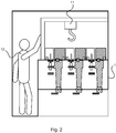
- These removable modules are accessible from above on one horizontal plane for the automation system to lift them from their operating position and replace them with spare module. Also, as shown in Fig. 2 this also facilitates access via human controlled manipulation.
- the complexity of an automation system is reduced, because a single portal crane with three degrees of freedom can be used first to drive to selected coordinates on the horizontal plane and then performing the lifting operation in the third (vertical) direction.
- the automation system weight handling requirements are also reduced, because the load center of gravity is always below the manipulator, thereby avoiding torque.
- FIG. 1 the replaceable modules are shown as separate boxes/modules, each one containing auxiliaries of one switching device. However, the boxes/modules can be merged to form one bigger box/module for all three phases or one bigger box/module for both circuit breaker and disconnector. The primary parts of these devices, if designed withdrawable, can be attached to the box/module as well to form one bigger and heavier removable module.
- Fig. 1 The design of the switchgear or control gear of Fig. 1 is shown with phases separated and single pole circuit breaker units. Rearrangement of state-of-art switchgear and controlgear design, with three phase switching devices is also possible.
- the disconnector switch in Fig.1 is shown as a linear movement type, but this also can be a disconnector switch with rotational movement.
- the removable module of the circuit breaker shown in Fig.1 includes the control electronics and auxiliaries and allows a simple electrical plug and socket connection to the circuit breaker drive.
- the module can also include parts of the CB drive, and then the interface to the CB pole can be a removable mechanical connection transferring mechanical energy from the drive to the CB moving contact.
- the removable module can comprise the complete circuit breaker single pole unit (the pole including drive and auxiliaries). For that purpose it is possible to use a rotational circuit breaker pole.
- the vacuum interrupter located in the central axis of the pole is then used for current interruption, while rotation of the pole around the central axis serves for connection, disconnection and earthing as a three position disconnector switch.
- Fig. 2 shows a detailed example of a switchgear or control gear designed specifically for human operation, where for ease of reference the following features shown are listed:
- the switchgear or control gear has been equipped with a manually operated lifting system.
- the primary circuit can include other components and devices not described in Fig.1 , such as earthing switch, voltage indication, surge arrestors, Ultra Fast Earthing Switch (UFES), IS-limiters (as invented by ABB Calor Emag in 1955), contactors, load-break switches, fuses.
- UFES Ultra Fast Earthing Switch
Landscapes
- Engineering & Computer Science (AREA)
- Power Engineering (AREA)
- Gas-Insulated Switchgears (AREA)
- Driving Mechanisms And Operating Circuits Of Arc-Extinguishing High-Tension Switches (AREA)
Claims (30)
- Appareillage de commutation ou de commande, comprenant :- au moins un premier compartiment (1, 5, 9) ;- une pluralité de modules amovibles (6, 7) ;- une pluralité de composants d'appareillage de commutation ou de commande principaux ; et- une pluralité de composants d'appareillage de commutation ou de commande auxiliaires ;
où la pluralité de composants d'appareillage de commutation ou de commande principaux comprennent au moins un système de barres omnibus principal (2), au moins un sectionneur à mouvement linéaire ou rotatif à trois positions (3), au moins un disjoncteur (4) et au moins une connexion de câble ;
où la pluralité de composants d'appareillage de commutation ou de commande auxiliaires comprennent au moins un mécanisme d'entraînement de sectionneur et au moins un mécanisme d'entraînement de disjoncteur ;
où la pluralité de modules amovibles sont configurés pour être montés horizontalement dans l'au moins un premier compartiment à une pluralité d'emplacements horizontaux ;
où la pluralité de composants d'appareillage de commutation ou de commande principaux sont configurés pour être logés dans l'au moins un premier compartiment ;
où la pluralité de composants d'appareillage de commutation ou de commande auxiliaires sont logés dans, ou associés à, la pluralité de modules amovibles ;
où chacun des modules amovibles est configuré pour être déplacé verticalement depuis son emplacement horizontal ; et
où le déplacement d'un module amovible depuis son emplacement horizontal, le déplacement comprenant un déplacement vertical, est configuré pour déplacer le ou les composants auxiliaires logés dans, ou associés à, ce module amovible. - Appareillage de commutation ou de commande selon la revendication 1, dans lequel l'appareillage de commutation ou de commande comprend un système de maintenance automatique situé à l'intérieur de l'au moins un premier compartiment, et où le système de maintenance automatique est configuré pour déplacer chacun de la pluralité de modules amovibles.
- Appareillage de commutation ou de commande selon la revendication 1, dans lequel chacun des modules amovibles est configuré pour être retiré de l'au moins un premier compartiment, et où le retrait d'un module amovible de l'au moins un premier compartiment comprend le déplacement du module amovible, et où le retrait du module amovible est configuré pour retirer les un ou plusieurs composants auxiliaires logés dans, ou associés à, ce module amovible de l'au moins un premier compartiment.
- Appareillage de commutation ou de commande selon la revendication 3, dans lequel l'appareillage de commutation ou de commande comprend un système de levage actionné manuellement, configuré pour déplacer et/ou retirer chacun de la pluralité de modules amovibles.
- Appareillage de commutation ou de commande selon l'une quelconque des revendications 1 à 4, dans lequel la pluralité des composants d'appareillage de commutation ou de commande auxiliaires sont divisés en une pluralité de groupes logiques, et où les composants d'un groupe logique sont logés dans ou associés au même module amovible.
- Appareillage de commutation ou de commande selon la revendication 5, dans lequel au moins un auxiliaire est associé à l'au moins un mécanisme d'entraînement de sectionneur, et où un ou plusieurs mécanismes d'entraînement de sectionneur de l'au moins un mécanisme d'entraînement de sectionneur et un ou plusieurs auxiliaires associés sont logés dans un premier module amovible.
- Appareillage de commutation ou de commande selon la revendication 6, dans lequel trois mécanismes d'entraînement de sectionneur et trois ensembles d'auxiliaires associés sont logés dans le premier module amovible.
- Appareillage de commutation ou de commande selon la revendication 6, dans lequel trois mécanismes d'entraînement de sectionneur et trois ensembles d'auxiliaires associés sont logés dans trois modules amovibles différents, dont l'un est le premier module amovible.
- Appareillage de commutation ou de commande selon l'une quelconque des revendications 6 à 8, dans lequel un ou plusieurs sectionneurs à mouvement linéaire ou rotatif à trois positions parmi l'au moins un sectionneur à mouvement linéaire ou rotatif à trois positions sont logés dans ou associés au premier module amovible.
- Appareillage de commutation ou de commande selon la revendication 9, dans lequel les sectionneurs à mouvement linéaire ou rotatif à trois positions sont logés dans ou associés au premier module amovible.
- Appareillage de commutation ou de commande selon la revendication 9, lorsqu'elle est subordonnée à la revendication 8, dans lequel les sectionneurs à mouvement linéaire ou rotatif à trois positions sont logés dans, ou associés, aux trois modules amovibles différents.
- Appareillage de commutation ou de commande selon l'une quelconque des revendications 5 à 11, dans lequel au moins un auxiliaire est associé à l'au moins un mécanisme d'entraînement de disjoncteur, et où un ou plusieurs mécanismes d'entraînement de disjoncteurs de l'au moins un mécanisme d'entraînement de disjoncteur et un ou plusieurs auxiliaires associés sont logés dans, ou associés à, un deuxième module amovible.
- Appareillage de commutation ou de commande selon la revendication 12, dans lequel un mécanisme d'entraînement de disjoncteur commun pour les trois phases et un ensemble d'auxiliaires associés communs pour les trois phases sont logés dans ou associés au deuxième module amovible.
- Appareillage de commutation ou de commande selon la revendication 12, dans lequel trois mécanismes d'entraînement de disjoncteur et trois ensembles d'auxiliaires associés sont logés dans ou associés au deuxième module amovible.
- Appareillage de commutation ou de commande selon la revendication 12, dans lequel trois mécanismes d'entraînement de disjoncteur et trois ensembles d'auxiliaires associés sont logés dans, ou associés à, trois modules amovibles différents, dont l'un est le deuxième module amovible.
- Appareillage de commutation ou de commande selon l'une quelconque des revendications 12 à 15, dans lequel un ou plusieurs disjoncteurs de l'au moins un disjoncteur sont logés dans ou associés au deuxième module amovible.
- Appareillage de commutation ou de commande selon la revendication 16, dans lequel trois disjoncteurs sont logés dans ou associés au deuxième module amovible.
- Appareillage de commutation ou de commande selon la revendication 16, lorsqu'elle est subordonnée à la revendication 14, dans lequel trois disjoncteurs sont logés dans ou associés aux trois modules amovibles différents.
- Appareillage de commutation ou de commande selon l'une quelconque des revendications 1 à 18, dans lequel l'au moins un premier compartiment est à l'épreuve des arcs.
- Appareillage de commutation ou de commande selon l'une quelconque des revendications 1 à 19, dans lequel chaque module amovible de l'au moins un module amovible comprend une connexion par fiche et prise à des circuits d'alimentation et de collecte de signaux, configurée pour permettre une communication et une connexion électrique avec au moins un composant externe au module amovible.
- Appareillage de commutation ou de commande selon la revendication 20, dans lequel une connexion par fiche et prise de l'au moins une connexion par fiche et prise est configurée pour une connexion électrique entre un mécanisme d'entraînement de disjoncteur de l'au moins un mécanisme d'entraînement de disjoncteur et un disjoncteur de l'au moins un disjoncteur.
- Appareillage de commutation ou de commande selon l'une quelconque des revendications 1 à 21, dans lequel l'au moins un premier compartiment comprend un compartiment de connexion de câble (5) à l'intérieur duquel est logée l'au moins une connexion de câble ; et où l'au moins un système de barres omnibus principal, l'au moins un sectionneur à mouvement linéaire ou rotatif à trois positions, et l'au moins un disjoncteur ne sont pas logés dans le compartiment de connexion de câble.
- Appareillage de commutation ou de commande selon la revendication 22, dans lequel au moins une traversée (10) fait partie de la connexion entre l'au moins une connexion de câble et l'au moins un disjoncteur, et où l'au moins une traversée comprend des capteurs de courant et de tension.
- Appareillage de commutation ou de commande selon l'une quelconque des revendications 22 et 23, dans lequel le compartiment de connexion de câble comprend au moins une porte ou une section de paroi amovible.
- Appareillage de commutation ou de commande selon l'une quelconque des revendications 22 à 24, dans lequel une paroi de séparation du compartiment de connexion de câble est une séparation à l'épreuve des arcs, permettant l'accès d'un utilisateur au compartiment de connexion de câble lorsqu'au moins un composant externe au compartiment de connexion de câble mais à l'intérieur de l'au moins un premier compartiment est opérationnel.
- Appareillage de commutation ou de commande selon l'une quelconque des revendications 22 à 25, dans lequel, en plus du compartiment de connexion de câble, l'au moins un premier compartiment comprend un premier compartiment (9) et un deuxième compartiment ; et dans lequel l'au moins un système de barres omnibus principal, l'au moins un sectionneur à trois positions ou à mouvement rotatif, et l'au moins un disjoncteur sont logés dans le deuxième compartiment.
- Appareillage de commutation ou de commande selon la revendication 26, dans lequel le premier compartiment comprend au moins une porte ou une section de paroi amovible.
- Appareillage de commutation ou de commande selon l'une quelconque des revendications 26 à 27, dans lequel au moins une paroi de séparation du premier compartiment (9) est une séparation à l'épreuve des arcs, permettant l'accès d'un utilisateur au premier compartiment de l'au moins un premier compartiment lorsqu'au moins un composant externe au premier compartiment de l'au moins un premier compartiment mais à l'intérieur de l'au moins un premier compartiment est opérationnel.
- Appareillage de commutation ou de commande selon l'une quelconque des revendications 1 à 28, dans lequel un module amovible, à l'intérieur duquel sont logés ou associés des éléments électroniques de commande de disjoncteur et des auxiliaires, loge également, ou est associé à, au moins une partie d'un mécanisme d'entraînement de disjoncteur, et où une interface avec un pôle de disjoncteur comprend une connexion mécanique amovible configurée pour transférer de l'énergie mécanique du mécanisme d'entraînement de disjoncteur à un contact mobile de disjoncteur.
- Appareillage de commutation ou de commande selon la revendication 29, dans lequel une unité unipolaire de disjoncteur est logée dans ou associée au module amovible, où l'unité unipolaire de disjoncteur utilise un pôle de disjoncteur rotatif, où un interrupteur à vide situé dans un axe central du pôle sert de dispositif de commutation de courant principal tandis que la rotation du pôle autour de l'axe central est configurée pour agir comme commutateur de sectionneur à trois positions pour la connexion, la déconnexion et la mise à la terre.
Priority Applications (4)
| Application Number | Priority Date | Filing Date | Title |
|---|---|---|---|
| ES18214235T ES2887257T3 (es) | 2018-12-19 | 2018-12-19 | Aparato de conmutación o aparato de control |
| EP18214235.6A EP3671992B1 (fr) | 2018-12-19 | 2018-12-19 | Appareillage de commutation ou de commande |
| CN201911312462.6A CN111342385B (zh) | 2018-12-19 | 2019-12-18 | 开关装置或控制装置 |
| US16/720,018 US11139642B2 (en) | 2018-12-19 | 2019-12-19 | Switchgear or control gear |
Applications Claiming Priority (1)
| Application Number | Priority Date | Filing Date | Title |
|---|---|---|---|
| EP18214235.6A EP3671992B1 (fr) | 2018-12-19 | 2018-12-19 | Appareillage de commutation ou de commande |
Publications (2)
| Publication Number | Publication Date |
|---|---|
| EP3671992A1 EP3671992A1 (fr) | 2020-06-24 |
| EP3671992B1 true EP3671992B1 (fr) | 2021-06-16 |
Family
ID=64755144
Family Applications (1)
| Application Number | Title | Priority Date | Filing Date |
|---|---|---|---|
| EP18214235.6A Active EP3671992B1 (fr) | 2018-12-19 | 2018-12-19 | Appareillage de commutation ou de commande |
Country Status (4)
| Country | Link |
|---|---|
| US (1) | US11139642B2 (fr) |
| EP (1) | EP3671992B1 (fr) |
| CN (1) | CN111342385B (fr) |
| ES (1) | ES2887257T3 (fr) |
Families Citing this family (4)
| Publication number | Priority date | Publication date | Assignee | Title |
|---|---|---|---|---|
| EP3671986B1 (fr) * | 2018-12-19 | 2025-05-14 | ABB Schweiz AG | Appareillage de commutation |
| EP4546580A3 (fr) * | 2018-12-19 | 2025-07-02 | Abb Schweiz Ag | Appareillage de commutation triphasé utilisant un équipement monophasé dans un boîtier unique |
| EP3671988A1 (fr) * | 2018-12-19 | 2020-06-24 | ABB Schweiz AG | Installation des commutateurs hermétiquement fermée avec un seul compartiment pour disjoncteur, un déconnecteur à trois positions et une barre de bus principale. |
| EP4089700A1 (fr) * | 2021-05-14 | 2022-11-16 | ABB Schweiz AG | Commutateur de déconnexion à trois positions |
Family Cites Families (13)
| Publication number | Priority date | Publication date | Assignee | Title |
|---|---|---|---|---|
| CN2701132Y (zh) * | 2004-05-26 | 2005-05-18 | 镇江龙源电器有限公司 | 户内高压复合绝缘金属封闭开关设备 |
| DE102009036590B3 (de) * | 2009-08-07 | 2011-03-31 | Abb Technology Ag | Gasisolierte Hochspannungsschaltanlage |
| EP2346126B1 (fr) * | 2010-01-18 | 2018-07-04 | ABB Schweiz AG | Appareil de commutation moyenne tension à isolement dans l'air |
| DE102010063130A1 (de) * | 2010-12-15 | 2012-06-21 | Abb Technology Ag | Schaltschrank zum Betreiben einer Mittel- oder Hochspannungsschaltanlage |
| EP2958205B1 (fr) * | 2013-02-13 | 2019-03-27 | Mitsubishi Electric Corporation | Appareillage de connexion à isolation gazeuse |
| CN104868394B (zh) * | 2015-05-15 | 2018-12-04 | 厦门柏瑞科电气有限公司 | 一种侧装中置开关柜 |
| EP3136414B1 (fr) | 2015-08-31 | 2019-06-26 | ABB Schweiz AG | Appareillage de commutation moyenne tension à isolation gazeuse avec un agencement de partie pôle de disjoncteur |
| CN105680358B (zh) * | 2016-03-21 | 2018-06-29 | 南阳市鑫特电气有限公司 | 一种旋转抽出式高压真空断路器 |
| CN106601543A (zh) * | 2016-08-13 | 2017-04-26 | 信尔德科技有限公司 | 高压真空断路器 |
| EP3422502B1 (fr) | 2017-06-28 | 2021-04-07 | ABB Schweiz AG | Sous-station pour haute ou moyenne tension, contenant un commutateur ou un équipement de commande avec fonctionnement et entretien sans équipage |
| EP3422501B1 (fr) | 2017-06-28 | 2021-04-28 | ABB Schweiz AG | Robot à fonctionnement et maintenance sans personnel dans un station à moyenne ou haute tension |
| EP3422503A1 (fr) | 2017-06-28 | 2019-01-02 | ABB Schweiz AG | Manipulateur de robot interne pour fonctionnement et entretien sans pilote dans des disjoncteurs débrochables, et procédé de fonctionnement du robot-manipulateur |
| EP3421190B1 (fr) | 2017-06-28 | 2022-05-04 | ABB Schweiz AG | Appareillage de commutation à fonctionnement et maintenance sans personnel et procédé de fonctionnement associé |
-
2018
- 2018-12-19 EP EP18214235.6A patent/EP3671992B1/fr active Active
- 2018-12-19 ES ES18214235T patent/ES2887257T3/es active Active
-
2019
- 2019-12-18 CN CN201911312462.6A patent/CN111342385B/zh active Active
- 2019-12-19 US US16/720,018 patent/US11139642B2/en active Active
Also Published As
| Publication number | Publication date |
|---|---|
| CN111342385A (zh) | 2020-06-26 |
| US20200203935A1 (en) | 2020-06-25 |
| EP3671992A1 (fr) | 2020-06-24 |
| CN111342385B (zh) | 2022-03-04 |
| US11139642B2 (en) | 2021-10-05 |
| ES2887257T3 (es) | 2021-12-22 |
Similar Documents
| Publication | Publication Date | Title |
|---|---|---|
| US11139642B2 (en) | Switchgear or control gear | |
| US11682885B2 (en) | Switchgear | |
| EP1218995B1 (fr) | Appareillage de commutation isole par gaz | |
| US11637414B2 (en) | Three phase switchgear using single phase equipment in single casing | |
| EP2405544A2 (fr) | Agencement de commutateur à selection de double système de barres omnibus | |
| JP5791832B2 (ja) | ガス絶縁スイッチギヤ | |
| US11005240B2 (en) | Three phase switchgear or control gear | |
| EP1983625A1 (fr) | Compartiment amovible à utiliser dans une unité fonctionnelle d'une installation de commutation électrique | |
| KR101203912B1 (ko) | 스위치 기어 | |
| US8379373B2 (en) | Vacuum insulated switchgear including a bus recovery member | |
| US7310220B2 (en) | High voltage outdoor substation | |
| US11670919B2 (en) | Three phase switchgear or control gear | |
| JP2014096914A (ja) | スイッチギヤまたはスイッチギヤ内の遮断器交換方法 | |
| CZ11978U1 (cs) | Dvousystémová kobková rozvodna | |
| HK1159866A (zh) | 开关装置 |
Legal Events
| Date | Code | Title | Description |
|---|---|---|---|
| PUAI | Public reference made under article 153(3) epc to a published international application that has entered the european phase |
Free format text: ORIGINAL CODE: 0009012 |
|
| STAA | Information on the status of an ep patent application or granted ep patent |
Free format text: STATUS: THE APPLICATION HAS BEEN PUBLISHED |
|
| AK | Designated contracting states |
Kind code of ref document: A1 Designated state(s): AL AT BE BG CH CY CZ DE DK EE ES FI FR GB GR HR HU IE IS IT LI LT LU LV MC MK MT NL NO PL PT RO RS SE SI SK SM TR |
|
| AX | Request for extension of the european patent |
Extension state: BA ME |
|
| STAA | Information on the status of an ep patent application or granted ep patent |
Free format text: STATUS: REQUEST FOR EXAMINATION WAS MADE |
|
| 17P | Request for examination filed |
Effective date: 20201125 |
|
| RBV | Designated contracting states (corrected) |
Designated state(s): AL AT BE BG CH CY CZ DE DK EE ES FI FR GB GR HR HU IE IS IT LI LT LU LV MC MK MT NL NO PL PT RO RS SE SI SK SM TR |
|
| GRAP | Despatch of communication of intention to grant a patent |
Free format text: ORIGINAL CODE: EPIDOSNIGR1 |
|
| STAA | Information on the status of an ep patent application or granted ep patent |
Free format text: STATUS: GRANT OF PATENT IS INTENDED |
|
| INTG | Intention to grant announced |
Effective date: 20210113 |
|
| GRAS | Grant fee paid |
Free format text: ORIGINAL CODE: EPIDOSNIGR3 |
|
| GRAA | (expected) grant |
Free format text: ORIGINAL CODE: 0009210 |
|
| STAA | Information on the status of an ep patent application or granted ep patent |
Free format text: STATUS: THE PATENT HAS BEEN GRANTED |
|
| AK | Designated contracting states |
Kind code of ref document: B1 Designated state(s): AL AT BE BG CH CY CZ DE DK EE ES FI FR GB GR HR HU IE IS IT LI LT LU LV MC MK MT NL NO PL PT RO RS SE SI SK SM TR |
|
| RAP3 | Party data changed (applicant data changed or rights of an application transferred) |
Owner name: ABB SCHWEIZ AG |
|
| REG | Reference to a national code |
Ref country code: GB Ref legal event code: FG4D |
|
| REG | Reference to a national code |
Ref country code: CH Ref legal event code: EP |
|
| REG | Reference to a national code |
Ref country code: DE Ref legal event code: R096 Ref document number: 602018018627 Country of ref document: DE |
|
| REG | Reference to a national code |
Ref country code: AT Ref legal event code: REF Ref document number: 1403122 Country of ref document: AT Kind code of ref document: T Effective date: 20210715 |
|
| REG | Reference to a national code |
Ref country code: IE Ref legal event code: FG4D |
|
| REG | Reference to a national code |
Ref country code: LT Ref legal event code: MG9D |
|
| PG25 | Lapsed in a contracting state [announced via postgrant information from national office to epo] |
Ref country code: BG Free format text: LAPSE BECAUSE OF FAILURE TO SUBMIT A TRANSLATION OF THE DESCRIPTION OR TO PAY THE FEE WITHIN THE PRESCRIBED TIME-LIMIT Effective date: 20210916 Ref country code: FI Free format text: LAPSE BECAUSE OF FAILURE TO SUBMIT A TRANSLATION OF THE DESCRIPTION OR TO PAY THE FEE WITHIN THE PRESCRIBED TIME-LIMIT Effective date: 20210616 Ref country code: HR Free format text: LAPSE BECAUSE OF FAILURE TO SUBMIT A TRANSLATION OF THE DESCRIPTION OR TO PAY THE FEE WITHIN THE PRESCRIBED TIME-LIMIT Effective date: 20210616 Ref country code: LT Free format text: LAPSE BECAUSE OF FAILURE TO SUBMIT A TRANSLATION OF THE DESCRIPTION OR TO PAY THE FEE WITHIN THE PRESCRIBED TIME-LIMIT Effective date: 20210616 |
|
| REG | Reference to a national code |
Ref country code: AT Ref legal event code: MK05 Ref document number: 1403122 Country of ref document: AT Kind code of ref document: T Effective date: 20210616 |
|
| REG | Reference to a national code |
Ref country code: NL Ref legal event code: MP Effective date: 20210616 |
|
| PG25 | Lapsed in a contracting state [announced via postgrant information from national office to epo] |
Ref country code: GR Free format text: LAPSE BECAUSE OF FAILURE TO SUBMIT A TRANSLATION OF THE DESCRIPTION OR TO PAY THE FEE WITHIN THE PRESCRIBED TIME-LIMIT Effective date: 20210917 Ref country code: LV Free format text: LAPSE BECAUSE OF FAILURE TO SUBMIT A TRANSLATION OF THE DESCRIPTION OR TO PAY THE FEE WITHIN THE PRESCRIBED TIME-LIMIT Effective date: 20210616 Ref country code: NO Free format text: LAPSE BECAUSE OF FAILURE TO SUBMIT A TRANSLATION OF THE DESCRIPTION OR TO PAY THE FEE WITHIN THE PRESCRIBED TIME-LIMIT Effective date: 20210916 Ref country code: RS Free format text: LAPSE BECAUSE OF FAILURE TO SUBMIT A TRANSLATION OF THE DESCRIPTION OR TO PAY THE FEE WITHIN THE PRESCRIBED TIME-LIMIT Effective date: 20210616 Ref country code: SE Free format text: LAPSE BECAUSE OF FAILURE TO SUBMIT A TRANSLATION OF THE DESCRIPTION OR TO PAY THE FEE WITHIN THE PRESCRIBED TIME-LIMIT Effective date: 20210616 |
|
| REG | Reference to a national code |
Ref country code: ES Ref legal event code: FG2A Ref document number: 2887257 Country of ref document: ES Kind code of ref document: T3 Effective date: 20211222 |
|
| PG25 | Lapsed in a contracting state [announced via postgrant information from national office to epo] |
Ref country code: SK Free format text: LAPSE BECAUSE OF FAILURE TO SUBMIT A TRANSLATION OF THE DESCRIPTION OR TO PAY THE FEE WITHIN THE PRESCRIBED TIME-LIMIT Effective date: 20210616 Ref country code: SM Free format text: LAPSE BECAUSE OF FAILURE TO SUBMIT A TRANSLATION OF THE DESCRIPTION OR TO PAY THE FEE WITHIN THE PRESCRIBED TIME-LIMIT Effective date: 20210616 Ref country code: EE Free format text: LAPSE BECAUSE OF FAILURE TO SUBMIT A TRANSLATION OF THE DESCRIPTION OR TO PAY THE FEE WITHIN THE PRESCRIBED TIME-LIMIT Effective date: 20210616 Ref country code: CZ Free format text: LAPSE BECAUSE OF FAILURE TO SUBMIT A TRANSLATION OF THE DESCRIPTION OR TO PAY THE FEE WITHIN THE PRESCRIBED TIME-LIMIT Effective date: 20210616 Ref country code: AT Free format text: LAPSE BECAUSE OF FAILURE TO SUBMIT A TRANSLATION OF THE DESCRIPTION OR TO PAY THE FEE WITHIN THE PRESCRIBED TIME-LIMIT Effective date: 20210616 Ref country code: PT Free format text: LAPSE BECAUSE OF FAILURE TO SUBMIT A TRANSLATION OF THE DESCRIPTION OR TO PAY THE FEE WITHIN THE PRESCRIBED TIME-LIMIT Effective date: 20211018 Ref country code: RO Free format text: LAPSE BECAUSE OF FAILURE TO SUBMIT A TRANSLATION OF THE DESCRIPTION OR TO PAY THE FEE WITHIN THE PRESCRIBED TIME-LIMIT Effective date: 20210616 Ref country code: NL Free format text: LAPSE BECAUSE OF FAILURE TO SUBMIT A TRANSLATION OF THE DESCRIPTION OR TO PAY THE FEE WITHIN THE PRESCRIBED TIME-LIMIT Effective date: 20210616 |
|
| PG25 | Lapsed in a contracting state [announced via postgrant information from national office to epo] |
Ref country code: PL Free format text: LAPSE BECAUSE OF FAILURE TO SUBMIT A TRANSLATION OF THE DESCRIPTION OR TO PAY THE FEE WITHIN THE PRESCRIBED TIME-LIMIT Effective date: 20210616 |
|
| REG | Reference to a national code |
Ref country code: DE Ref legal event code: R097 Ref document number: 602018018627 Country of ref document: DE |
|
| PLBE | No opposition filed within time limit |
Free format text: ORIGINAL CODE: 0009261 |
|
| STAA | Information on the status of an ep patent application or granted ep patent |
Free format text: STATUS: NO OPPOSITION FILED WITHIN TIME LIMIT |
|
| PG25 | Lapsed in a contracting state [announced via postgrant information from national office to epo] |
Ref country code: DK Free format text: LAPSE BECAUSE OF FAILURE TO SUBMIT A TRANSLATION OF THE DESCRIPTION OR TO PAY THE FEE WITHIN THE PRESCRIBED TIME-LIMIT Effective date: 20210616 |
|
| 26N | No opposition filed |
Effective date: 20220317 |
|
| PG25 | Lapsed in a contracting state [announced via postgrant information from national office to epo] |
Ref country code: AL Free format text: LAPSE BECAUSE OF FAILURE TO SUBMIT A TRANSLATION OF THE DESCRIPTION OR TO PAY THE FEE WITHIN THE PRESCRIBED TIME-LIMIT Effective date: 20210616 |
|
| PG25 | Lapsed in a contracting state [announced via postgrant information from national office to epo] |
Ref country code: MC Free format text: LAPSE BECAUSE OF FAILURE TO SUBMIT A TRANSLATION OF THE DESCRIPTION OR TO PAY THE FEE WITHIN THE PRESCRIBED TIME-LIMIT Effective date: 20210616 |
|
| REG | Reference to a national code |
Ref country code: CH Ref legal event code: PL |
|
| REG | Reference to a national code |
Ref country code: BE Ref legal event code: MM Effective date: 20211231 |
|
| PG25 | Lapsed in a contracting state [announced via postgrant information from national office to epo] |
Ref country code: LU Free format text: LAPSE BECAUSE OF NON-PAYMENT OF DUE FEES Effective date: 20211219 Ref country code: IE Free format text: LAPSE BECAUSE OF NON-PAYMENT OF DUE FEES Effective date: 20211219 |
|
| PG25 | Lapsed in a contracting state [announced via postgrant information from national office to epo] |
Ref country code: BE Free format text: LAPSE BECAUSE OF NON-PAYMENT OF DUE FEES Effective date: 20211231 |
|
| PG25 | Lapsed in a contracting state [announced via postgrant information from national office to epo] |
Ref country code: LI Free format text: LAPSE BECAUSE OF NON-PAYMENT OF DUE FEES Effective date: 20211231 Ref country code: CH Free format text: LAPSE BECAUSE OF NON-PAYMENT OF DUE FEES Effective date: 20211231 |
|
| PG25 | Lapsed in a contracting state [announced via postgrant information from national office to epo] |
Ref country code: CY Free format text: LAPSE BECAUSE OF FAILURE TO SUBMIT A TRANSLATION OF THE DESCRIPTION OR TO PAY THE FEE WITHIN THE PRESCRIBED TIME-LIMIT Effective date: 20210616 |
|
| PG25 | Lapsed in a contracting state [announced via postgrant information from national office to epo] |
Ref country code: HU Free format text: LAPSE BECAUSE OF FAILURE TO SUBMIT A TRANSLATION OF THE DESCRIPTION OR TO PAY THE FEE WITHIN THE PRESCRIBED TIME-LIMIT; INVALID AB INITIO Effective date: 20181219 |
|
| GBPC | Gb: european patent ceased through non-payment of renewal fee |
Effective date: 20221219 |
|
| PG25 | Lapsed in a contracting state [announced via postgrant information from national office to epo] |
Ref country code: GB Free format text: LAPSE BECAUSE OF NON-PAYMENT OF DUE FEES Effective date: 20221219 |
|
| PG25 | Lapsed in a contracting state [announced via postgrant information from national office to epo] |
Ref country code: MK Free format text: LAPSE BECAUSE OF FAILURE TO SUBMIT A TRANSLATION OF THE DESCRIPTION OR TO PAY THE FEE WITHIN THE PRESCRIBED TIME-LIMIT Effective date: 20210616 |
|
| PG25 | Lapsed in a contracting state [announced via postgrant information from national office to epo] |
Ref country code: TR Free format text: LAPSE BECAUSE OF FAILURE TO SUBMIT A TRANSLATION OF THE DESCRIPTION OR TO PAY THE FEE WITHIN THE PRESCRIBED TIME-LIMIT Effective date: 20210616 |
|
| PG25 | Lapsed in a contracting state [announced via postgrant information from national office to epo] |
Ref country code: MT Free format text: LAPSE BECAUSE OF FAILURE TO SUBMIT A TRANSLATION OF THE DESCRIPTION OR TO PAY THE FEE WITHIN THE PRESCRIBED TIME-LIMIT Effective date: 20210616 |
|
| PGFP | Annual fee paid to national office [announced via postgrant information from national office to epo] |
Ref country code: DE Payment date: 20251211 Year of fee payment: 8 |
|
| PGFP | Annual fee paid to national office [announced via postgrant information from national office to epo] |
Ref country code: IT Payment date: 20251223 Year of fee payment: 8 |
|
| PGFP | Annual fee paid to national office [announced via postgrant information from national office to epo] |
Ref country code: FR Payment date: 20251229 Year of fee payment: 8 |
|
| PGFP | Annual fee paid to national office [announced via postgrant information from national office to epo] |
Ref country code: ES Payment date: 20260130 Year of fee payment: 8 |