EP3671999B1 - Système, dispositif et procédé pour faciliter le nouage d'un noeud - Google Patents
Système, dispositif et procédé pour faciliter le nouage d'un noeud Download PDFInfo
- Publication number
- EP3671999B1 EP3671999B1 EP19212691.0A EP19212691A EP3671999B1 EP 3671999 B1 EP3671999 B1 EP 3671999B1 EP 19212691 A EP19212691 A EP 19212691A EP 3671999 B1 EP3671999 B1 EP 3671999B1
- Authority
- EP
- European Patent Office
- Prior art keywords
- groove
- circumferential groove
- fixture
- lead member
- tie
- Prior art date
- Legal status (The legal status is an assumption and is not a legal conclusion. Google has not performed a legal analysis and makes no representation as to the accuracy of the status listed.)
- Active
Links
Images




Classifications
-
- B—PERFORMING OPERATIONS; TRANSPORTING
- B65—CONVEYING; PACKING; STORING; HANDLING THIN OR FILAMENTARY MATERIAL
- B65B—MACHINES, APPARATUS OR DEVICES FOR, OR METHODS OF, PACKAGING ARTICLES OR MATERIALS; UNPACKING
- B65B13/00—Bundling articles
- B65B13/18—Details of, or auxiliary devices used in, bundling machines or bundling tools
- B65B13/24—Securing ends of binding material
- B65B13/26—Securing ends of binding material by knotting
- B65B13/265—Hand tools
-
- H—ELECTRICITY
- H02—GENERATION; CONVERSION OR DISTRIBUTION OF ELECTRIC POWER
- H02G—INSTALLATION OF ELECTRIC CABLES OR LINES, OR OF COMBINED OPTICAL AND ELECTRIC CABLES OR LINES
- H02G1/00—Methods or apparatus specially adapted for installing, maintaining, repairing or dismantling electric cables or lines
- H02G1/06—Methods or apparatus specially adapted for installing, maintaining, repairing or dismantling electric cables or lines for laying cables, e.g. laying apparatus on vehicle
-
- B—PERFORMING OPERATIONS; TRANSPORTING
- B65—CONVEYING; PACKING; STORING; HANDLING THIN OR FILAMENTARY MATERIAL
- B65B—MACHINES, APPARATUS OR DEVICES FOR, OR METHODS OF, PACKAGING ARTICLES OR MATERIALS; UNPACKING
- B65B13/00—Bundling articles
- B65B13/18—Details of, or auxiliary devices used in, bundling machines or bundling tools
- B65B13/24—Securing ends of binding material
- B65B13/26—Securing ends of binding material by knotting
-
- B—PERFORMING OPERATIONS; TRANSPORTING
- B65—CONVEYING; PACKING; STORING; HANDLING THIN OR FILAMENTARY MATERIAL
- B65B—MACHINES, APPARATUS OR DEVICES FOR, OR METHODS OF, PACKAGING ARTICLES OR MATERIALS; UNPACKING
- B65B13/00—Bundling articles
- B65B13/02—Applying and securing binding material around articles or groups of articles, e.g. using strings, wires, strips, bands or tapes
- B65B13/025—Hand-held tools
-
- B—PERFORMING OPERATIONS; TRANSPORTING
- B65—CONVEYING; PACKING; STORING; HANDLING THIN OR FILAMENTARY MATERIAL
- B65B—MACHINES, APPARATUS OR DEVICES FOR, OR METHODS OF, PACKAGING ARTICLES OR MATERIALS; UNPACKING
- B65B13/00—Bundling articles
- B65B13/18—Details of, or auxiliary devices used in, bundling machines or bundling tools
-
- B—PERFORMING OPERATIONS; TRANSPORTING
- B65—CONVEYING; PACKING; STORING; HANDLING THIN OR FILAMENTARY MATERIAL
- B65B—MACHINES, APPARATUS OR DEVICES FOR, OR METHODS OF, PACKAGING ARTICLES OR MATERIALS; UNPACKING
- B65B27/00—Bundling particular articles presenting special problems using string, wire, or narrow tape or band; Baling fibrous material, e.g. peat, not otherwise provided for
- B65B27/10—Bundling rods, sticks, or like elongated objects
-
- B—PERFORMING OPERATIONS; TRANSPORTING
- B65—CONVEYING; PACKING; STORING; HANDLING THIN OR FILAMENTARY MATERIAL
- B65H—HANDLING THIN OR FILAMENTARY MATERIAL, e.g. SHEETS, WEBS, CABLES
- B65H69/00—Methods of, or devices for, interconnecting successive lengths of material; Knot-tying devices ;Control of the correct working of the interconnecting device
- B65H69/04—Methods of, or devices for, interconnecting successive lengths of material; Knot-tying devices ;Control of the correct working of the interconnecting device by knotting
- B65H69/043—Methods of, or devices for, interconnecting successive lengths of material; Knot-tying devices ;Control of the correct working of the interconnecting device by knotting the threads are moved in ducts having the form of the wanted knot
-
- F—MECHANICAL ENGINEERING; LIGHTING; HEATING; WEAPONS; BLASTING
- F16—ENGINEERING ELEMENTS AND UNITS; GENERAL MEASURES FOR PRODUCING AND MAINTAINING EFFECTIVE FUNCTIONING OF MACHINES OR INSTALLATIONS; THERMAL INSULATION IN GENERAL
- F16L—PIPES; JOINTS OR FITTINGS FOR PIPES; SUPPORTS FOR PIPES, CABLES OR PROTECTIVE TUBING; MEANS FOR THERMAL INSULATION IN GENERAL
- F16L3/00—Supports for pipes, cables or protective tubing, e.g. hangers, holders, clamps, cleats, clips, brackets
- F16L3/22—Supports for pipes, cables or protective tubing, e.g. hangers, holders, clamps, cleats, clips, brackets specially adapted for supporting a number of parallel pipes at intervals
- F16L3/23—Supports for pipes, cables or protective tubing, e.g. hangers, holders, clamps, cleats, clips, brackets specially adapted for supporting a number of parallel pipes at intervals for a bundle of pipes or a plurality of pipes placed side by side in contact with each other
- F16L3/233—Supports for pipes, cables or protective tubing, e.g. hangers, holders, clamps, cleats, clips, brackets specially adapted for supporting a number of parallel pipes at intervals for a bundle of pipes or a plurality of pipes placed side by side in contact with each other by means of a flexible band
Definitions
- the present disclosure relates generally to a technique for tying a knot and, more particularly, to a system, a device and a method to facilitate tying a knot.
- Wire bundles such as groups of wires, cables, conduits or other elongate members, are frequently secured together, such as at generally regular intervals, in order to facilitate proper wire bundle management.
- the wire bundle can be more readily maintained in a desired position as to avoid interference with other components and to reduce the risk that the wire bundle will be damaged.
- vehicles such as automobiles, aircraft or the like, oftentimes include wire bundles with the wire bundles secured at generally regular intervals.
- the wire bundles of commercial aircraft are generally secured at regular intervals of every one to three feet.
- the wire bundles are generally secured at more frequent intervals, such as every two to three inches.
- Cable ties such as zip ties
- zip ties and other types of cable ties disadvantageously add to the weight of the system that includes the wire bundle.
- Some systems, such as aircraft, may include long lengths of wire bundles and, as a result, may include many cable ties which, in the aggregate, contribute to the overall weight of the system.
- the increase in weight due to the cable ties, such as zip ties may increase fuel consumption, decrease range and the like.
- string may be utilized in order to tie a wire bundle so as to secure the wire bundle at generally regular intervals.
- a wire bundle may be tied with a clove hitch knot that provides for the secure retention of the wire bundle even as a system that includes the wire bundle, such as an aircraft, experiences various external forces.
- a knot such as a clove hitch knot, is generally lighter than a zip tie or other cable tie, thereby reducing the overall weight of the system including the wire bundle. With respect to an aircraft, for example, this reduction in weight may reduce fuel consumption, increase range or the like.
- some knots, such as clove hitch knots may be difficult to tie, at least on a repeated basis. Even if properly tied, some knots, such as clove hitch knots, may be time consuming to tie, thereby increasing assembly time and cost for the overall system.
- US2008/282645 A1 in accordance with its abstract, states a method and apparatus for applying a tie around the gathered open end or neck of a bag to close the bag.
- a feed device feeds a length of tie material to a former where the tie material is formed into a tie loop around the gathered open or neck of a bag inserted in the former. After forming the tie loop, a leading, free end of the tie material is held in a gripper device and the feed device for the tie material reversed to pull the tie material and close the tie loop around the gathered open end or neck of the bag.
- a cutter device cuts the tie material after the tying operation to allow the bag to be removed from the former with the tie secured thereto.
- a guard ring prevents tightening of the tie loop and requires the operator to use both hands to initiate removal of the guard ring so that the tie loop cannot be tightened with a part of the operators hand or fingers in the former.
- the gathered open end or neck of the bag is inserted into the former with a vacuum device.
- a system to facilitate tying a knot comprising: a fixture defining an internal passage therethrough, wherein the fixture defines a circumferential groove accessible through an interior surface of the fixture and in communication with the internal passage, wherein the circumferential groove includes first and second groove portions that cross one another, and wherein opposite ends of the circumferential groove are coincident and open through an opening defined by an exterior surface of the fixture; a supply of a tie member; and a lead member supply mechanism configured to alternately feed a lead member through the circumferential groove and to withdraw the lead member from the circumferential groove once the tie member is connected thereto, wherein the lead member supply mechanism comprises: a supply of the lead member; and one or more rotatable feed members configured to engage the lead member and to alternately feed the lead member and withdraw the lead member from the circumferential groove.
- a method to facilitate tying a knot comprising: positioning a fixture about a workpiece such that the workpiece extends through an internal passage defined by the fixture, wherein the fixture defines a circumferential groove accessible through an interior surface of the fixture and in communication with the internal passage, and wherein the circumferential groove includes first and second groove portions that cross one another; inserting a tie member through the circumferential groove such that the tie member extends lengthwise through the circumferential groove; forcing the tie member to move inward toward the workpiece and out of the circumferential groove; and removing the fixture from the workpiece to permit the knot to be formed from the tie member, wherein inserting the tie member through the circumferential groove comprises: feeding a lead member through the circumferential groove using one or more rotatable feed members; connecting the tie member to the lead member; and withdrawing the lead member from the circumferential groove using the one or more rotatable feed members such that the tie member is correspondingly inserted through the circumferential groove.
- a knot tied with assistance by the system, device and method of the present disclosure may be utilized to secure various workpieces including wire bundles, such as a wire bundle carried by vehicles, such as automobiles, aircraft or the like.
- wire bundles such as a wire bundle carried by vehicles, such as automobiles, aircraft or the like.
- the system, device and method of the present disclosure permit knots to be tied in a reliable manner and to be tied more expeditiously, thereby potentially reducing installation time and cost.
- the system, device and method of the present disclosure permit a workpiece, such as a wire bundle, to be secured with a string, as opposed to a zip tie or other cable tie, thereby reducing the overall weight and potentially reducing fuel consumption and increasing range relative to the use of cable ties.
- a device to facilitate tying a knot that includes a fixture defining an internal passage therethrough.
- the fixture defines a circumferential groove accessible through an interior surface of the fixture and in communication with the internal passage.
- the groove includes first and second groove portions that cross one another. Opposite ends of the groove are coincident and open through an opening defined by an exterior surface of the fixture.
- the groove further includes a third groove portion parallel to the first groove portion.
- the second and third groove portions cross one another, and the first, second and third groove portions are disposed sequentially between the opposite ends of the groove.
- the first and second groove portions have different depths.
- the groove includes a channel and a neck extending between the channel and the interior surface of the fixture. The neck has a smaller width than the channel.
- the fixture includes first and second fixture components that cooperate to define the first and second groove portions of the groove. The first fixture component defines the first and second groove portions to cross one another and the second fixture component defines the first and second groove portions to have a parallel relationship.
- a system to facilitate tying a knot.
- the system includes a fixture defining an internal passage therethrough.
- the fixture defines a circumferential groove accessible through an interior surface of the fixture and in communication with the internal passage.
- the groove includes first and second groove portions that cross one another.
- the system also includes a lead member supply mechanism configured to alternately feed a lead member through the groove and to withdraw the lead member from the groove once a tie member is connected thereto.
- the lead member supply mechanism is configured to feed the lead member through the groove by pushing the lead member lengthwise through the groove in a first direction and to withdraw the lead member from the groove by retracting the lead member from the groove such that the tie member is pulled through the groove in a second direction, opposite the first direction.
- opposite ends of the groove are coincident and open through an opening defined through an exterior surface of the fixture.
- the lead member supply mechanism is configured to feed the lead member through the groove by inserting the lead member through the opening and into the groove and to withdraw the lead member from the groove by withdrawing the lead member through the opening.
- the lead member supply mechanism includes a supply of the lead member and one or more feed members configured to engage the lead member and to alternately feed the lead member to and withdraw the lead member from the groove.
- the system also includes a supply of the tie member; and a housing that engages and positionally maintains the fixture, supplies of the lead member and the tie member and the one or more rotatable feed wheels.
- the groove further includes a third groove portion parallel to the first groove portion with the second and third groove portions crossing one another.
- the first, second and third groove portions of this example are disposed sequentially between the opposite ends of the groove.
- the first and second groove portions have different depths.
- the groove of an example includes a channel and a neck extending between the channel and the interior surface of the fixture. The neck of this example has a smaller width than the channel.
- the fixture includes first and second fixture components that cooperate to define the first and second groove portions of the groove.
- the first fixture component defines the first and second groove portions to cross one another and the second fixture component defines the first and second groove portions to have a parallel relationship.
- a method to facilitate tying a knot.
- the method includes positioning a fixture about a workpiece such that the workpiece extends through an internal passage defined by the fixture.
- the fixture defines a circumferential groove accessible through an interior surface of the fixture and in communication with the internal passage.
- the groove includes first and second groove portions that cross one another.
- the method also includes inserting a tie member through the groove such that the tie member extends lengthwise through the groove.
- the method further includes forcing the tie member to move inward toward the workpiece and out of the groove and removing the fixture from the workpiece to permit the knot to be formed from the tie member.
- the method inserts the tie member through the groove by feeding a lead member through the groove, connecting the tie member to the lead member and withdrawing the lead member from the groove such that the tie member is correspondingly inserted through the groove.
- the method feeds the lead member through the groove by pushing the lead member lengthwise through the groove in a first direction, and the method also withdraws the lead member by retracting the lead member from the groove such that the tie member is pulled through the groove in a second direction, opposite the first direction.
- the method feeds the lead member through the groove by pushing the lead member lengthwise through the groove in a first direction, and the method also withdraws the lead member by pulling the lead member from the groove such that the tie member connected to the lead member is also pulled through the groove in the first direction.
- the first and second groove portions have different depths such that the lead member that extends through one of the first or second groove portions is inward of and crosses the lead member that extends through another of the first or second groove portions.
- the groove includes a channel and a neck extending between the channel and an interior surface of the fixture that faces the workpiece. In some examples in which the neck has a smaller width than the channel, the method inserts the tie member through the groove by inserting the tie member through the channel of the groove, and the method also forces the tie member to move inward toward the workpiece and out of the groove by forcing the tie member from the channel and through the neck of the groove so as to move out of move out of the groove.
- a system, device and method are provided in accordance with some examples in order to facilitate tying a knot, such as a clove hitch knot.
- the system, device and method facilitate tying a knot with a string about a workpiece.
- Knots may be tied about a variety of workpieces so as to secure the respective workpieces.
- the workpiece is a wire bundle, such as a bundle of wires, cables, conduits or other elongate members.
- the workpiece, such as a wire bundle, secured by the knots may be employed in a variety of different applications.
- a wire bundle secured by one or more knots may extend through a vehicle, such as an automobile, an aircraft, a space vehicle or the like, in order to interconnect various components of the vehicle.
- an elongate workpiece 10, such as a wire bundle is depicted.
- the workpiece 10 is secured at regular or generally regular intervals by a string in which a knot 12, such as a clove hitch knot, is formed.
- a knot 12 such as a clove hitch knot
- two knots 12 are depicted at locations spaced apart along the elongate workpiece 10, such as the elongate wire bundle.
- the workpiece 10 of Figure 1 is depicted to be secured by a plurality of knots 12 at regular intervals therealong, the workpiece may be secured by any number of knots with the knots being spaced at either regular or irregular intervals.
- a device 14 in accordance with an example has engaged the workpiece 10 in order to facilitate tying another knot 12 about the workpiece.
- the device 14 includes a fixture 16.
- the fixture 16 defines an internal passage 18 centered about a longitudinal axis 20 extending through the internal passage.
- the internal passage 18 is sized to receive the workpiece 10, such as a wire bundle, such that the workpiece extends through the internal passage defined by the fixture 16.
- the fixture 16 of some examples includes first and second fixture components 22, 24.
- the fixture 16 may have a clamshell design so as to alternately open and close about a workpiece 10, such as a wire bundle.
- the first and second fixture components 22, 24 may be pivotably joined, such as by being mounted on a hinge 26 about which the first and second fixture components rotate.
- the first and second fixture components 22, 24 need not be pivotably joined so as to alternately open and close about a workpiece 10 and may, instead, be differently configured while still permitting the first and second fixture components to alternately be positioned about a workpiece as shown in Figure 1 and then removed and separately from the workpiece.
- the fixture 16 also defines a circumferential groove 28 opening through an interior surface 30 of the fixture and into the internal passage 18.
- the circumferential groove 28 extends lengthwise and continuously between opposed ends 28a, 28b, as shown in Figure 2B .
- the opposite ends 28a, 28b of the groove 28 are coincident and open through an exterior surface 32 of the fixture 16.
- the portion of the second fixture component 24 that is aligned with and adjacent to the opening may also define a portion of the opening such that the portions of the opening defined by the first and second fixture components cooperate to comprise the opening.
- the fixture 16 of this example also defines an opening 34 through the exterior surface 32 that serves as both of the opposed ends 28a, 28b of the circumferential groove 28 defined by the fixture.
- the portions of the opening 34 defined by the first and second fixture components 22, 24 may be aligned as illustrated. Or, the portions of the opening 34 defined by the first and second fixture components 22, 24 may be offset from one another with the portion of the opening defined by one fixture component serving as one end 28a of the circumferential groove 28 and the portion of the opening defined by the other fixture component serving as the other end 28b of the circumferential groove.
- the groove 28 may transition to the opening 34 in various manners, but, in some examples, the groove smoothly curves to the opening.
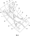
- the circumferential groove 28 defined by the fixture 16 extends circumferentially at least twice and, in some examples, three or more times about the internal passage 18 defined by the fixture. In the illustrated example, the circumferential groove 28 extends three times about the internal passage 18 defined by the fixture 16.
- the circumferential groove 28 therefore includes a plurality of groove portions, each of which extends once, that is, 360°, about the internal passage 18 defined by the fixture 16.
- the plurality of groove portions are disposed sequentially such that in the illustrated example in which the circumferential groove 28 extends three times about the internal passage 18 defined by the fixture 16, the circumferential groove includes three groove portions, namely, a first groove portion 38 that extends from the opening 34 defined through the exterior surface 32 of the fixture 360° about the internal passage defined by the fixture to the second groove portion 40.
- the second groove portion 40 then also extends 360° about the internal passage to the third groove portion 42.
- the third groove portion 42 then extends from the second groove portion 40 360° about the internal passage 18 defined by the fixture 16 to the opening 34 through the exterior surface 32 of the fixture.
- each groove portion is defined by each of the first and second fixture components such that the first and second fixture components cooperate to define the circumferential groove 28 in general and, more particularly, each of the first, second and third groove portions 38, 40, 42.
- first and second groove portions 38, 40 are defined by the fixture 16 and, more particularly, the first fixture component 22 so as to cross one another.
- the second and third groove portions 40, 42 may also be defined so as to cross one another.
- the first and third groove portions 38, 42 may be defined so as to be parallel to one another with the second groove portion 40 being defined so as to extend at an angle to both the first and third groove portions such that the second groove portion crosses both the first and third groove portions.
- the second fixture component 24 defines the groove portions, such as the first, second and third groove portions 38, 40, 42, so as to be parallel to one another.
- each of the first, second and third groove portions 38, 40, 42 lie in respective reference planes that are parallel to one another and are oriented perpendicular to the longitudinal axis 20 defined by the internal passage 18 through the fixture 16.
- the first fixture component 22 defines the groove portions and, in the illustrated example, the first, second and third groove portions 38, 40, 42 so as to lie in respective reference planes that are differently oriented relative to the longitudinal axis 20.
- first and third groove portions 38, 42 are parallel to one another and lie in respective planes that are parallel to one another and are offset in a first angular direction from a plane perpendicular to the longitudinal axis 20 by a predefined angle ⁇ as shown in Figure 3 .
- the second groove portion 40 lies in a reference plane that is offset in a second angular direction, opposite from the first angular direction, from the plane perpendicular to the longitudinal axis 20.
- the reference plane that contains the second groove portion 40 may not only be offset from the plane perpendicular to the longitudinal axis 20 in a different angular direction, but may also be offset to a greater degree, such as by being offset from the plane perpendicular to the longitudinal axis by twice the angle (-2 ⁇ ) at which the reference planes that contain the first and third groove portions are offset from the plane perpendicular to the longitudinal axis.
- the circumferential groove 28 of the illustrated example begins with the first groove portion 38 that extends from the opening 34 extending through the exterior surface 32 of the fixture 16 at an angle, such as ⁇ , relative to a plane perpendicular to the longitudinal axis 20 about the first fixture component 22.
- the first groove portion 38 then continues through the second fixture component 24 about the remainder of the internal passage 18.
- the first groove portion 38 defined by the second fixture component 24 is at a different angle, such as 0°, with respect to the plane perpendicular to the longitudinal axis 20 (by lying, for example, in the plane perpendicular to the longitudinal axis) than the first groove portion defined by the first fixture component 22.
- the circumferential groove 28 then continues with the second groove portion 40 being defined by the first fixture component 22 at a different angle, such as an angle of -2 ⁇ , relative to a plane perpendicular to the longitudinal axis 20 than the first groove portion 38.
- the second groove portion 40 then continues through the second fixture component 24 about the remainder of the internal passage 18.
- the second groove portion 40 defined by the second fixture component 24 is at a different angle, such as 0°, with respect to the plane perpendicular to the longitudinal axis 20 (by lying, for example, in the plane perpendicular to the longitudinal axis) than the second groove portion defined by the first fixture component 22.
- the third groove portion 42 then continues from the second groove portion 40 at an angle, such as ⁇ , relative to a plane perpendicular to the longitudinal axis 20 about the first fixture component 22.
- the third groove portion 42 then continues through the second fixture component 24 about the remainder of the internal passage 18 to the opening 34 defined through the exterior surface 32 of the fixture 16.
- the third groove portion 42 defined by the second fixture component 24 is at a different angle, such as 0°, with respect to the plane perpendicular to the longitudinal axis 20 (by lying, for example, in the plane perpendicular to the longitudinal axis) than the third groove portion defined by the first fixture component 22.
- the circumferential groove 28 comprised of the first, second and third groove portions 38, 40, 42 begins at the opening 34 defined through the exterior surface 32 of the fixture 16 and extends continuously in a lengthwise direction three times about the internal passage 18 before ending at the same opening through the exterior surface of the fixture.
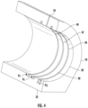
- the circumferential groove 28 may have various configurations and shapes. In some examples, as shown in more detail in Figure 5 , however, the circumferential groove 28 includes a channel 44 and a neck 46 extending between the channel and the interior surface 30 of the fixture 16.
- the neck 46 has a smaller width W 2 than the width Wi of the channel 44, as measured in a widthwise direction perpendicular to the lengthwise direction in which the groove extends.
- a tie member may be disposed within the channel 44 and while the tie member may be forced through the neck 46 of the groove 28, the tie member will otherwise be retained within the channel in the absence of a force causing the tie member to move from the channel, through the neck and into the internal passage 18.
- the fixture 16 may be formed in various manners, the fixture of some examples may be additively manufactured or laser printed.
- the channel 44 of some examples includes angled surfaces that converge to the neck 46, such as shown in Figure 5 .
- a pliable member such as a rubber gasket or a plurality of bristles, is positioned and held within the neck 46 of the circumferential groove 28 so as to extend into the passageway defined by the neck.
- the pliable member further biases a tie member to remain within the channel 44 and prevents inadvertent removal of the tie member from the channel while still permitting the tie member to be extracted through the neck 46 from the channel upon the application of an external force to the tie member as described below.
- first and second groove portions 38, 40 have different depths as measured relative to the interior surface 30 of the fixture 16.
- first and third groove portions 38, 42 may have the same depth Di and the second groove portion 40 may have a different depth D 2 than either the first or third groove portions.
- the second groove portion 40 has a greater depth D 2 than the depth Di of the first and third groove portions 38, 42, thereby extending further into the fixture 16 from the interior surface 30 thereof.
- the fixture 16 of some examples is configured such that the part of the second groove portion that crosses the first and third groove portions (namely, the part of the second groove portion circled at 40a in Figure 3 ) is deeper than the corresponding parts of the first and third groove portions, but the other parts of the first, second and third groove portions may have the same depth.
- the first fixture component 22 defines the second groove portion 40 to have a greater depth than the first and third groove portions 38, 42 defined by the first fixture component, while the second fixture component 24 defines the second groove portion to have the same depth as the first and third groove portions.
- the fixture 16 permits a knot 12, such as a clove hitch knot, to be tied about a workpiece 10, such as a wire bundle.
- a tie member such as a string
- the tie member may be inserted through the opening 34 defined through the exterior surface 32 of the fixture 16 and into the first groove portion 38 and, more particularly, the channel 44 of the first groove portion.
- the insertion of the tie member 56 continues through the first groove portion 38 (as indicated by the arrows designated 1 in Figure 3 ) and into the second groove portion 40 (as indicated by the arrows designated 2) and, in turn, the third groove portion 42 (as indicated by the arrows designated 3) prior to emerging from the fixture 16 through the opening 34 defined through the exterior surface 32 of the fixture.
- the tie member 56 can extend sequentially through the first, second and third groove portions and can cross over itself as a result of the manner in which the second groove portion crosses the first and second groove portions.
- the tie member is then forced to move inward toward the workpiece 10 and out of the groove 28.
- the tie member is forced to move through the neck 46 of the circumferential groove 28 and into the internal passage 18 defined by the fixture 16 so as to be in closer proximity to and, in some examples, in contact with the workpiece 10, such as a wire bundle, extending therethrough.
- the tie member is forced out of the groove 28 in some examples by applying a pulling force to the portions of the tie member that extend outward from the opening 34 defined by the exterior surface 32 of the fixture 16.
- the portions of the tie member that extend through the opening 34 defined by the exterior surface 32 of the fixture 16 may be pulled in a direction away from the fixture or in other directions that tend to pull the tie member out of the opening defined by the exterior surface of the fixture.
- the application of this force to the tie member 56 causes the length of tie member within the fixture 16 that is extends through the circumferential groove 28 to shorten and be pulled through the neck 46 of the groove, thereby cinching about the workpiece, such as the wire bundle, as illustrated in Figure 5 .
- the fixture 16 may then be removed from the workpiece 10 as shown in block 64, such as by opening the first and second fixture components 22, 24.
- the opposed portions, such as the end portions, of the tie member are pulled through the opening 34 defined by the exterior surface 32 of the fixture 16 as the fixture is removed from the workpiece 10 such that the tie member remains wrapped about the workpiece, such as the wire bundle, in the configuration defined by the circumferential groove 28.
- the ends of the tie member may then be tied, such as in a double knot, thereby resulting in a knot 12, such as a clove hitch knot as a result of the pattern defined by the circumferential groove 28.
- the tie member may be inserted through the circumferential groove 28 by hand, such as by pushing the tie member through the circumferential groove.
- a lead member may initially be inserted through the groove 28, such as by being pushed through the groove. While sufficiently flexible to follow the circumferential groove 28 about the internal passage 18, the lead member is more rigid than the tie member.
- the lead member may be formed of a metal, such as spring steel, and may be in the form of a flat ribbon. A first end of the lead member may be inserted into the groove 28 and the tie member may be attached, such as by a clip, to an opposed second end of the lead member. The lead member may then be inserted in a first direction through the groove.
- the first end of the lead member may be pulled such that the lead member is pulled lengthwise in a first direction from the groove while the tie member attached to the lead member is correspondingly pulled in the first direction into the groove.
- the tie member may be detached from the lead member and the process of forming a knot 12 may continue as described above, such as by pulling the opposed ends of the tie member outwardly relative to the fixture 16 in order to cause the tie member to move out of the groove and to cinch about the workpiece 10, such as the wire bundle, prior to removing the fixture.
- a system is provided to facilitate tying a knot 12 and, more particularly, to facilitate insertion of the tie member through the circumferential groove 28.
- the system 50 includes a fixture 16, such as described above, and a lead member supply mechanism 52.
- the lead member supply mechanism 52 is configured to alternately feed a lead member 54, such as a spring member, e.g., a spring steel member in the form of a flat ribbon, through the groove 28 and to withdraw the lead member from the groove once the tie member 56 is connected thereto.
- the lead member supply mechanism 52 is configured to push the lead member 54 lengthwise through the groove 28 in a first direction, such as by inserting the lead member through the opening 34 defined by the exterior surface 32 of the fixture and 16 into the circumferential groove.
- the lead member 54 may be extended through the entire length of the circumferential groove 28 so as to emerge from the fixture 16 through the same opening 34 defined through the exterior surface 32 thereof.
- the tie member 56 may then be connected to the lead member 54, such as by means of a clip, e.g., an alligator clip.
- the lead member supply mechanism 52 is then configured to withdraw the lead member 54 from the groove 28 by retracting the lead member from the groove such that the tie member 56 is pulled through the groove by the lead member.
- the lead member supply mechanism 52 is configured to withdraw the lead member 54 from the groove 28 by withdrawing the lead member through the same opening 34 defined by the exterior surface 32 of the fixture 16 with the tie member 56 connected thereto.
- the tie member 56 is correspondingly pulled through the groove 28.
- the tie member 56 may then be disengaged from the lead member 54 such that the opposed ends of the tie member extend through the opening 34 defined by the exterior surface 32 of the fixture 16.
- a force may then be applied to the opposed ends of the tie member 56 in order to force the tie member to move inward toward the workpiece 10 and out of the groove 28 prior to removing the fixture 16 from the workpiece and permitting the knot 12 having the configuration defined by the circumferential groove of the fixture to be tied.
- the lead member supply mechanism 52 is configured to push the lead member 54 lengthwise through the groove in a first direction (such that the lead member initially enters the third groove portion 42 prior to be pushed through the second groove portion 40 and finally the first groove portion 38) and to subsequently withdraw the lead member from the groove by retracting the lead member from the groove such that the tie member is pulled through the groove in a second direction, opposite the first direction.
- the lead member supply mechanism 52 may include a supply of the lead member 54, such as a coil of the lead member.
- the lead member 54 may be formed, in some examples, by a flat spring material, such as a flat spring steel material.
- the lead member supply mechanism 52 of this example also includes an actuator, such as a linear actuator and, in some examples, one or more rotatable feed members 58, such as a pair of opposed feed wheels, configured to engage the lead member 54 and to alternately feed the lead member to and withdraw the lead member from the groove 28 defined by the fixture 16.
- the feed member(s) 58 may be driven so as to controllably rotate in order to correspondingly cause the lead member to be fed to the groove 28 when rotated in a first direction or withdrawn from the groove when rotated in a second direction, opposite the first direction.
- the system 50 of some examples includes a trigger 70 that can be repeatedly actuated in order to controllably rotate the feed member(s).
- the actuation of the trigger 0 may be configured to cause the feed member(s) 58 to rotate in a predefined direction by a predefined amount.
- the feed member(s) 58 may be repeatedly rotated, thereby providing for a ratcheting-type advancement or withdrawal of the lead member 54.
- the direction in which the feed member(s) 58 rotate and, as a result, whether the lead member 54 is inserted into or withdrawn from the circumferential groove 28 may be defined by a selection mechanism (not shown) such as a toggle switch, that permits a user to alternately configure the system 50 to cause the one or more feed member(s) to rotate so as to insert the lead member into the circumferential groove or, alternately, to withdraw the lead member from the groove.
- the lead member 54 may assume a coiled position in the absence of external forces. While engaged by the one or more feed member(s) 58, the lead member 54 may be advanced through the circumferential groove 28.
- the feed member(s) 58 may be configured to disengage from the lead member, such as by being raised relative to the lead member, and the lead member may then return to its coiled position, thereby withdrawing the lead member from the groove.
- the system 50 of the example of Figure 8 also includes a supply of the tie member 56, such as a spool 72 about which the tie member is wound.
- the spool 72 is configured to rotate, such as in a clockwise direction in the orientation of Figure 8 , in order to permit the tie member 56 to be drawn from the spool following attachment to the lead member 54 and withdrawal of the lead member through the groove 28.
- the system 50 can include a housing 74, one side of which has been removed to permit the other components of the system to be more clearly illustrated.
- the housing 74 engages and positionally maintains the fixture 16, the supplies of the lead member 54 and the tie member 56 and the one or more rotatable feed member(s) 58.
- the tie member 56 can be inserted through the circumferential groove 28 utilizing the system 50 of Figure 8 by initially feeding the lead member 54 through the groove and then connecting the tie member 56 to the lead member, such as with a clip.
- the lead member 54 may then be withdrawn from the groove 28 such that the tie member 56 is correspondingly inserted into the groove, such as by being pulled through the groove by the lead member.
- the lead member 54 may be fed through the groove 28 by pushing the lead member lengthwise through the groove in a first direction.
- the lead member of this example may then be withdrawn from the groove 28 by retracting the lead member from the groove such that the tie member 56 is pulled through the groove in a second direction, opposite the first direction.
- the system 50 of some examples may also include a cutting mechanism, such as a knife blade, for cutting the opposed portions of the tie member 56 that extend beyond the fixture 16, such as in response to user actuation.
- a cutting mechanism such as a knife blade
- the system 50, device 14 and method of the present disclosure thereby facilitate tying a knot 12, such as a clove hitch knot, about a workpiece 10, such as a wire bundle.
- knots 12 may be more reliably and more efficiently tied about the workpiece 10.
- string can be utilized to tie and secure the workpiece 10, such as the wire bundle, thereby avoiding the additional weight imposed if a comparable number of cable ties, such as zip ties, were utilized.
- knots, such as clove hitch knots may be reliably tied, thereby increasing the security with which the workpiece 10 is bound.
Landscapes
- Engineering & Computer Science (AREA)
- Mechanical Engineering (AREA)
- General Engineering & Computer Science (AREA)
- Basic Packing Technique (AREA)
- Clamps And Clips (AREA)
Claims (15)
- Système (50) pour faciliter la réalisation d'un noeud, le système (50) comprenant :un montage (16) définissant un passage interne (18) à travers celui-ci, dans lequel le montage (16) définit une rainure circonférentielle (28) accessible par l'intermédiaire d'une surface intérieure (30) du montage (16) et en communication avec le passage interne (18),dans lequel la rainure circonférentielle (28) comprend des première et deuxième parties de rainure (38, 40) qui se croisent mutuellement, etdans lequel des extrémités opposées (28a, 28b) de la rainure circonférentielle (28) coïncident et s'ouvrent à travers une ouverture (34) définie par une surface extérieure du montage (16) ;une distribution d'un élément de liaison (56) ; etun mécanisme de distribution d'élément principal (52) configuré pour, en alternance, alimenter un élément principal (54) à travers la rainure circonférentielle (28) et retirer l'élément principal (54) de la rainure circonférentielle (28) une fois que l'élément de liaison (56) est relié à celui-ci, dans lequel le mécanisme de distribution d'élément principal (52) comprend :une distribution de l'élément principal (54) ; etun ou plusieurs éléments d'alimentation rotatifs (58) configurés pour mettre en prise l'élément principal (54) et pour, en alternance, alimenter l'élément principal (54) et retirer l'élément principal (54) de la rainure circonférentielle (28).
- Système selon la revendication 1 dans lequel la rainure circonférentielle (28) comprend en outre une troisième partie de rainure (42) parallèle à la première partie de rainure (38), dans lequel les deuxième et troisième parties de rainure (40, 42) se croisent mutuellement, et dans lequel les première, deuxième et troisième parties de rainure (38, 40, 42) sont disposées séquentiellement entre les extrémités opposées (28a, 28b) de la rainure circonférentielle (28).
- Système (50) selon l'une quelconque des revendications 1 à 2 dans lequel les première et deuxième parties de rainure (38, 40) ont différentes profondeurs (D1, D2).
- Système (50) selon l'une quelconque des revendications 1 à 3 dans lequel la rainure circonférentielle (28) comprend un canal (44) et un col (46) s'étendant entre le canal (44) et la surface intérieure (30) du montage (16), dans lequel le col (46) a une largeur plus faible que le canal (44).
- Système (50) selon l'une quelconque des revendications 1 à 4 dans lequel le montage (16) comprend des premier et deuxième composants de montage (22, 24) qui coopèrent pour définir les première et deuxième parties de rainure (38, 40) de la rainure circonférentielle (28).
- Système (50) selon la revendication 5 dans lequel le premier composant de montage (22) définit les première et deuxième parties de rainure (38, 40) de façon à se croiser mutuellement et le deuxième composant de montage (24) définit les première et deuxième parties de rainure (38, 40) de façon à avoir une relation parallèle.
- Système selon l'une quelconque des revendications précédentes, le système comprenant en outre :
un boîtier qui met en prise et maintient un position le montage, les distributions de l'élément principal (54) et de l'élément de liaison (56) et les un ou plusieurs éléments d'alimentation rotatifs (58). - Système selon l'une quelconque des revendications précédentes dans lequel le mécanisme de distribution d'élément principal (52) est configuré pour alimenter l'élément principal (54) à travers la rainure circonférentielle (28) par insertion de l'élément principal (54) à travers l'ouverture (34) et dans la rainure circonférentielle (28) et pour retirer l'élément principal (54) de la rainure circonférentielle (28) par retrait de l'élément principal (54) à travers l'ouverture (34).
- Système selon l'une quelconque des revendications précédentes dans lequel le montage (16) est fabriqué de façon additive ou imprimé au laser.
- Procédé pour faciliter la réalisation d'un noeud (12), le procédé comprenant :le positionnement d'un montage (16) autour d'une pièce (10) de sorte que la pièce (10) s'étend à travers un passage interne (18) défini par le montage (16), dans lequel le montage (16) définit une rainure circonférentielle (28) accessible à travers une surface intérieure (30) du montage (16) et en communication avec le passage interne (18), et dans lequel la rainure circonférentielle (28) comprend des première et deuxième parties de rainure (38, 40) qui se croisent mutuellement ;l'insertion d'un élément de liaison (56) à travers la rainure circonférentielle (28) de sorte que l'élément de liaison (56) s'étend de façon longitudinale à travers la rainure circonférentielle (28) ;le forçage de l'élément de liaison (56) à se déplacer vers l'intérieur dans la direction de la pièce (10) et hors de la rainure circonférentielle (28) ; etle retrait du montage (16) de la pièce (10) pour permettre que le noeud (12) soit formé à partir de l'élément de liaison (56), dans lequel l'insertion de l'élément de liaison (56) à travers la rainure circonférentielle (28) comprend :l'alimentation d'un élément principal (54) à travers la rainure circonférentielle (28) au moyen d'un ou plusieurs éléments d'alimentation rotatifs (58) ;le raccordement de l'élément de liaison (56) à l'élément principal (54) ; etle retrait de l'élément principal (54) de la rainure circonférentielle (28) au moyen des un ou plusieurs éléments d'alimentation rotatifs (58) de sorte que l'élément de liaison (56) soit inséré en correspondance à travers la rainure circonférentielle (28).
- Procédé selon la revendication 10 dans lequel l'alimentation de l'élément principal (54) à travers la rainure circonférentielle (28) comprend la poussée de l'élément principal (54) dans la direction longitudinale à travers la rainure circonférentielle (28) dans une première direction, et dans lequel le retrait de l'élément principal (54) comprend la rétraction de l'élément principal (54) depuis la rainure circonférentielle (28) de sorte que l'élément de liaison (56) soit tiré à travers la rainure circonférentielle (28) dans une deuxième direction, opposée à la première direction.
- Procédé selon la revendication 10 dans lequel l'alimentation de l'élément principal (54) à travers la rainure circonférentielle (28) comprend la poussée de l'élément principal (54) dans la direction longitudinale à travers la rainure circonférentielle (28) dans une première direction, et dans lequel le retrait de l'élément principal (54) comprend la traction de l'élément principal (54) depuis la rainure circonférentielle (28) de sorte que l'élément de liaison (56) relié à l'élément principal (54) est également tiré à travers la rainure circonférentielle (28) dans la première direction.
- Procédé selon l'une quelconque des revendications 10 à 12 dans lequel les première et deuxième parties de rainure (38, 40) ont des profondeurs différentes de sorte que l'élément principal (54) qui s'étend à travers l'une des première ou deuxième parties de rainure (38, 40) est vers l'intérieur de, et croise, l'élément principal (54) qui s'étend à travers une autre des première ou deuxième parties de rainure (38, 40).
- Procédé selon l'une quelconque des revendications 10 à 13 dans lequel la rainure circonférentielle (28) comprend un canal (44) et un col (46) s'étend entre le canal (44) et une surface intérieure (30) du montage (16) qui fait face à la pièce (10), dans lequel le col (46) a une largeur plus faible que le canal (44), dans lequel l'insertion de l'élément de liaison (56) à travers la rainure circonférentielle (28) comprend l'insertion de l'élément de liaison (56) à travers le canal (44) de la rainure circonférentielle (28).
- Procédé selon l'une quelconque des revendications 10 à 14 dans lequel le forçage de l'élément de liaison (56) à se déplacer vers l'intérieur dans la direction de la pièce (10) et hors de la rainure circonférentielle (28) comprend le forçage de l'élément de liaison (56) depuis le canal (44) et à travers le col (46) de la rainure circonférentielle (28) de façon à se déplacer hors de la rainure circonférentielle (28) .
Applications Claiming Priority (1)
| Application Number | Priority Date | Filing Date | Title |
|---|---|---|---|
| US16/223,949 US11970297B2 (en) | 2018-12-18 | 2018-12-18 | System, device and method to facilitate tying a knot |
Publications (2)
| Publication Number | Publication Date |
|---|---|
| EP3671999A1 EP3671999A1 (fr) | 2020-06-24 |
| EP3671999B1 true EP3671999B1 (fr) | 2024-03-27 |
Family
ID=68807989
Family Applications (1)
| Application Number | Title | Priority Date | Filing Date |
|---|---|---|---|
| EP19212691.0A Active EP3671999B1 (fr) | 2018-12-18 | 2019-11-29 | Système, dispositif et procédé pour faciliter le nouage d'un noeud |
Country Status (4)
| Country | Link |
|---|---|
| US (1) | US11970297B2 (fr) |
| EP (1) | EP3671999B1 (fr) |
| JP (1) | JP7388889B2 (fr) |
| CN (1) | CN111332517B (fr) |
Families Citing this family (2)
| Publication number | Priority date | Publication date | Assignee | Title |
|---|---|---|---|---|
| US12035492B2 (en) * | 2021-08-06 | 2024-07-09 | International Business Machines Corporation | Preloaded flexible latch assembly |
| CN113682516B (zh) * | 2021-09-17 | 2023-02-07 | 荣成康元食品有限公司 | 一种纤维绳带自动打结系统 |
Family Cites Families (19)
| Publication number | Priority date | Publication date | Assignee | Title |
|---|---|---|---|---|
| US876573A (en) | 1907-02-13 | 1908-01-14 | F W Griffin | Knot-tying apparatus for bags &c. |
| US3057648A (en) * | 1960-12-14 | 1962-10-09 | Develop Amatic Engineering | Cable lacer |
| JPS52103296A (en) | 1976-02-21 | 1977-08-30 | Max Co Ltd | Process for feeding pliable material |
| GB1562333A (en) | 1976-02-21 | 1980-03-12 | Max Co Ltd | Automatic binder |
| JPS53106377U (fr) * | 1977-01-29 | 1978-08-26 | ||
| JPS53106377A (en) | 1977-02-28 | 1978-09-16 | Amada Co Ltd | Device for die setting in press brake |
| DE3337853A1 (de) | 1983-10-18 | 1985-04-25 | Siemens AG, 1000 Berlin und 8000 München | Verfahren zum binden eines buendels elektrischer leitungen sowie zugehoerige vorrichtung |
| US5816140A (en) * | 1997-12-30 | 1998-10-06 | Langston Companies, Inc. | Bale wire tying apparatus and method |
| JP2000085718A (ja) * | 1998-09-04 | 2000-03-28 | Naonobu Tatebayashi | 結束バンドの結束装置 |
| US6363843B1 (en) * | 1999-09-02 | 2002-04-02 | L&P Property Management Company | Wire tie guide with tying device and method |
| US6279970B1 (en) | 2000-06-20 | 2001-08-28 | Michael Torres | Automatic knot-tying device |
| US6419283B1 (en) | 2000-10-24 | 2002-07-16 | Belmont Textile Machinery Company | Automatic knot-tying machine |
| US7661634B2 (en) * | 2002-02-08 | 2010-02-16 | Dt Search & Designs, Llc | Keyed channel strut mounted connector device |
| US6648378B1 (en) | 2002-10-04 | 2003-11-18 | Via Science Llc | Automatic knot-tying device |
| GB0523157D0 (en) * | 2005-11-14 | 2005-12-21 | Sirane Ltd | Packaging |
| US8622440B2 (en) | 2010-10-05 | 2014-01-07 | Ideal Industries, Inc. | Knot tying device and cartridge system for providing tying filament thereto |
| US8573656B1 (en) * | 2011-12-06 | 2013-11-05 | S.S. Steiner, Inc. | Knot-tying device and method |
| US20180178934A1 (en) | 2016-12-22 | 2018-06-28 | Gulfstream Aerospace Corporation | Ultrasonic cable tie system |
| ES2836109T3 (es) * | 2017-02-10 | 2021-06-24 | Airbus Defence & Space Sau | Cabezal de atado |
-
2018
- 2018-12-18 US US16/223,949 patent/US11970297B2/en active Active
-
2019
- 2019-11-14 JP JP2019206254A patent/JP7388889B2/ja active Active
- 2019-11-29 EP EP19212691.0A patent/EP3671999B1/fr active Active
- 2019-12-13 CN CN201911285345.5A patent/CN111332517B/zh active Active
Also Published As
| Publication number | Publication date |
|---|---|
| US11970297B2 (en) | 2024-04-30 |
| EP3671999A1 (fr) | 2020-06-24 |
| US20200189775A1 (en) | 2020-06-18 |
| JP2020114752A (ja) | 2020-07-30 |
| JP7388889B2 (ja) | 2023-11-29 |
| CN111332517A (zh) | 2020-06-26 |
| CN111332517B (zh) | 2023-04-07 |
Similar Documents
| Publication | Publication Date | Title |
|---|---|---|
| US7246789B2 (en) | Cable clamping apparatus and method | |
| US6186451B1 (en) | Cable tie | |
| US7934697B2 (en) | Apparatus and methods for gripping an elongated item | |
| US9481102B1 (en) | Spacer for a cable tie tensioning and severing tool | |
| US3653099A (en) | Bundle tie device | |
| EP3671999B1 (fr) | Système, dispositif et procédé pour faciliter le nouage d'un noeud | |
| US11027902B2 (en) | Integrated release feature for pawl-latching devices | |
| US9186804B2 (en) | Cutting tool and method of operating same | |
| CA2570455C (fr) | Colliers pour cables | |
| US20130139392A1 (en) | Cutting tool and method of operating same | |
| US5561903A (en) | Messenger removal tool | |
| US7735228B2 (en) | Insulation stripping tool | |
| DE102008022337A1 (de) | Vorrichtung und Verfahren zum automatisierten umfänglichen Umwickeln eines Kabelbaums mit einem Befestigungssystem bestehend aus einem Befestigungselement und einem Wickelband | |
| DE102020117522B4 (de) | Handgehaltenes bindewerkzeug | |
| EP1211187B1 (fr) | Dispositif permettant de couper la partie de languette depassant d'un collier de serrage | |
| EP0579432A1 (fr) | Verrouillage entre le ruban et la boucle d'une fermeture de ruban | |
| JP2003212204A (ja) | 結束装置 | |
| DE202017102503U1 (de) | Vorrichtung zum Umwickeln eines Leitungssatzes mit einem Band | |
| US10065329B2 (en) | Systems and methods for zip-tie cutting | |
| EP3796493B1 (fr) | Dispositif de montage d'un clip de fixation sur un élément de conduite | |
| EP0371044B1 (fr) | Outil de ficelage de faisceaux de cables ou similaires avec un ruban sans fin | |
| US6546853B2 (en) | Band tightening and cutting device | |
| JP2005343538A (ja) | 挟み型結束装置を用いた結束方法 | |
| JPH0710515U (ja) | 結束バンド | |
| JP2000050449A (ja) | ケーブル切断方法およびケーブル巻き込み防止機能付ケーブルカッター |
Legal Events
| Date | Code | Title | Description |
|---|---|---|---|
| PUAI | Public reference made under article 153(3) epc to a published international application that has entered the european phase |
Free format text: ORIGINAL CODE: 0009012 |
|
| STAA | Information on the status of an ep patent application or granted ep patent |
Free format text: STATUS: THE APPLICATION HAS BEEN PUBLISHED |
|
| AK | Designated contracting states |
Kind code of ref document: A1 Designated state(s): AL AT BE BG CH CY CZ DE DK EE ES FI FR GB GR HR HU IE IS IT LI LT LU LV MC MK MT NL NO PL PT RO RS SE SI SK SM TR |
|
| AX | Request for extension of the european patent |
Extension state: BA ME |
|
| STAA | Information on the status of an ep patent application or granted ep patent |
Free format text: STATUS: REQUEST FOR EXAMINATION WAS MADE |
|
| 17P | Request for examination filed |
Effective date: 20201208 |
|
| RBV | Designated contracting states (corrected) |
Designated state(s): AL AT BE BG CH CY CZ DE DK EE ES FI FR GB GR HR HU IE IS IT LI LT LU LV MC MK MT NL NO PL PT RO RS SE SI SK SM TR |
|
| STAA | Information on the status of an ep patent application or granted ep patent |
Free format text: STATUS: EXAMINATION IS IN PROGRESS |
|
| 17Q | First examination report despatched |
Effective date: 20210331 |
|
| RAP3 | Party data changed (applicant data changed or rights of an application transferred) |
Owner name: THE BOEING COMPANY |
|
| GRAP | Despatch of communication of intention to grant a patent |
Free format text: ORIGINAL CODE: EPIDOSNIGR1 |
|
| STAA | Information on the status of an ep patent application or granted ep patent |
Free format text: STATUS: GRANT OF PATENT IS INTENDED |
|
| INTG | Intention to grant announced |
Effective date: 20231113 |
|
| P01 | Opt-out of the competence of the unified patent court (upc) registered |
Effective date: 20231201 |
|
| GRAS | Grant fee paid |
Free format text: ORIGINAL CODE: EPIDOSNIGR3 |
|
| GRAA | (expected) grant |
Free format text: ORIGINAL CODE: 0009210 |
|
| STAA | Information on the status of an ep patent application or granted ep patent |
Free format text: STATUS: THE PATENT HAS BEEN GRANTED |
|
| AK | Designated contracting states |
Kind code of ref document: B1 Designated state(s): AL AT BE BG CH CY CZ DE DK EE ES FI FR GB GR HR HU IE IS IT LI LT LU LV MC MK MT NL NO PL PT RO RS SE SI SK SM TR |
|
| REG | Reference to a national code |
Ref country code: GB Ref legal event code: FG4D |
|
| REG | Reference to a national code |
Ref country code: CH Ref legal event code: EP |
|
| REG | Reference to a national code |
Ref country code: DE Ref legal event code: R096 Ref document number: 602019048937 Country of ref document: DE |
|
| REG | Reference to a national code |
Ref country code: IE Ref legal event code: FG4D |
|
| PG25 | Lapsed in a contracting state [announced via postgrant information from national office to epo] |
Ref country code: LT Free format text: LAPSE BECAUSE OF FAILURE TO SUBMIT A TRANSLATION OF THE DESCRIPTION OR TO PAY THE FEE WITHIN THE PRESCRIBED TIME-LIMIT Effective date: 20240327 |
|
| REG | Reference to a national code |
Ref country code: LT Ref legal event code: MG9D |
|
| PG25 | Lapsed in a contracting state [announced via postgrant information from national office to epo] |
Ref country code: GR Free format text: LAPSE BECAUSE OF FAILURE TO SUBMIT A TRANSLATION OF THE DESCRIPTION OR TO PAY THE FEE WITHIN THE PRESCRIBED TIME-LIMIT Effective date: 20240628 |
|
| PG25 | Lapsed in a contracting state [announced via postgrant information from national office to epo] |
Ref country code: HR Free format text: LAPSE BECAUSE OF FAILURE TO SUBMIT A TRANSLATION OF THE DESCRIPTION OR TO PAY THE FEE WITHIN THE PRESCRIBED TIME-LIMIT Effective date: 20240327 Ref country code: RS Free format text: LAPSE BECAUSE OF FAILURE TO SUBMIT A TRANSLATION OF THE DESCRIPTION OR TO PAY THE FEE WITHIN THE PRESCRIBED TIME-LIMIT Effective date: 20240627 |
|
| PG25 | Lapsed in a contracting state [announced via postgrant information from national office to epo] |
Ref country code: RS Free format text: LAPSE BECAUSE OF FAILURE TO SUBMIT A TRANSLATION OF THE DESCRIPTION OR TO PAY THE FEE WITHIN THE PRESCRIBED TIME-LIMIT Effective date: 20240627 Ref country code: NO Free format text: LAPSE BECAUSE OF FAILURE TO SUBMIT A TRANSLATION OF THE DESCRIPTION OR TO PAY THE FEE WITHIN THE PRESCRIBED TIME-LIMIT Effective date: 20240627 Ref country code: LT Free format text: LAPSE BECAUSE OF FAILURE TO SUBMIT A TRANSLATION OF THE DESCRIPTION OR TO PAY THE FEE WITHIN THE PRESCRIBED TIME-LIMIT Effective date: 20240327 Ref country code: HR Free format text: LAPSE BECAUSE OF FAILURE TO SUBMIT A TRANSLATION OF THE DESCRIPTION OR TO PAY THE FEE WITHIN THE PRESCRIBED TIME-LIMIT Effective date: 20240327 Ref country code: GR Free format text: LAPSE BECAUSE OF FAILURE TO SUBMIT A TRANSLATION OF THE DESCRIPTION OR TO PAY THE FEE WITHIN THE PRESCRIBED TIME-LIMIT Effective date: 20240628 Ref country code: FI Free format text: LAPSE BECAUSE OF FAILURE TO SUBMIT A TRANSLATION OF THE DESCRIPTION OR TO PAY THE FEE WITHIN THE PRESCRIBED TIME-LIMIT Effective date: 20240327 Ref country code: BG Free format text: LAPSE BECAUSE OF FAILURE TO SUBMIT A TRANSLATION OF THE DESCRIPTION OR TO PAY THE FEE WITHIN THE PRESCRIBED TIME-LIMIT Effective date: 20240327 |
|
| REG | Reference to a national code |
Ref country code: NL Ref legal event code: MP Effective date: 20240327 |
|
| PG25 | Lapsed in a contracting state [announced via postgrant information from national office to epo] |
Ref country code: SE Free format text: LAPSE BECAUSE OF FAILURE TO SUBMIT A TRANSLATION OF THE DESCRIPTION OR TO PAY THE FEE WITHIN THE PRESCRIBED TIME-LIMIT Effective date: 20240327 Ref country code: LV Free format text: LAPSE BECAUSE OF FAILURE TO SUBMIT A TRANSLATION OF THE DESCRIPTION OR TO PAY THE FEE WITHIN THE PRESCRIBED TIME-LIMIT Effective date: 20240327 |
|
| PG25 | Lapsed in a contracting state [announced via postgrant information from national office to epo] |
Ref country code: NL Free format text: LAPSE BECAUSE OF FAILURE TO SUBMIT A TRANSLATION OF THE DESCRIPTION OR TO PAY THE FEE WITHIN THE PRESCRIBED TIME-LIMIT Effective date: 20240327 |
|
| REG | Reference to a national code |
Ref country code: AT Ref legal event code: MK05 Ref document number: 1670847 Country of ref document: AT Kind code of ref document: T Effective date: 20240327 |
|
| PG25 | Lapsed in a contracting state [announced via postgrant information from national office to epo] |
Ref country code: NL Free format text: LAPSE BECAUSE OF FAILURE TO SUBMIT A TRANSLATION OF THE DESCRIPTION OR TO PAY THE FEE WITHIN THE PRESCRIBED TIME-LIMIT Effective date: 20240327 |
|
| PG25 | Lapsed in a contracting state [announced via postgrant information from national office to epo] |
Ref country code: IS Free format text: LAPSE BECAUSE OF FAILURE TO SUBMIT A TRANSLATION OF THE DESCRIPTION OR TO PAY THE FEE WITHIN THE PRESCRIBED TIME-LIMIT Effective date: 20240727 |
|
| PG25 | Lapsed in a contracting state [announced via postgrant information from national office to epo] |
Ref country code: PT Free format text: LAPSE BECAUSE OF FAILURE TO SUBMIT A TRANSLATION OF THE DESCRIPTION OR TO PAY THE FEE WITHIN THE PRESCRIBED TIME-LIMIT Effective date: 20240729 Ref country code: SM Free format text: LAPSE BECAUSE OF FAILURE TO SUBMIT A TRANSLATION OF THE DESCRIPTION OR TO PAY THE FEE WITHIN THE PRESCRIBED TIME-LIMIT Effective date: 20240327 |
|
| PG25 | Lapsed in a contracting state [announced via postgrant information from national office to epo] |
Ref country code: ES Free format text: LAPSE BECAUSE OF FAILURE TO SUBMIT A TRANSLATION OF THE DESCRIPTION OR TO PAY THE FEE WITHIN THE PRESCRIBED TIME-LIMIT Effective date: 20240327 |
|
| PG25 | Lapsed in a contracting state [announced via postgrant information from national office to epo] |
Ref country code: EE Free format text: LAPSE BECAUSE OF FAILURE TO SUBMIT A TRANSLATION OF THE DESCRIPTION OR TO PAY THE FEE WITHIN THE PRESCRIBED TIME-LIMIT Effective date: 20240327 Ref country code: CZ Free format text: LAPSE BECAUSE OF FAILURE TO SUBMIT A TRANSLATION OF THE DESCRIPTION OR TO PAY THE FEE WITHIN THE PRESCRIBED TIME-LIMIT Effective date: 20240327 |
|
| PG25 | Lapsed in a contracting state [announced via postgrant information from national office to epo] |
Ref country code: AT Free format text: LAPSE BECAUSE OF FAILURE TO SUBMIT A TRANSLATION OF THE DESCRIPTION OR TO PAY THE FEE WITHIN THE PRESCRIBED TIME-LIMIT Effective date: 20240327 |
|
| PG25 | Lapsed in a contracting state [announced via postgrant information from national office to epo] |
Ref country code: PL Free format text: LAPSE BECAUSE OF FAILURE TO SUBMIT A TRANSLATION OF THE DESCRIPTION OR TO PAY THE FEE WITHIN THE PRESCRIBED TIME-LIMIT Effective date: 20240327 |
|
| PG25 | Lapsed in a contracting state [announced via postgrant information from national office to epo] |
Ref country code: SK Free format text: LAPSE BECAUSE OF FAILURE TO SUBMIT A TRANSLATION OF THE DESCRIPTION OR TO PAY THE FEE WITHIN THE PRESCRIBED TIME-LIMIT Effective date: 20240327 |
|
| PG25 | Lapsed in a contracting state [announced via postgrant information from national office to epo] |
Ref country code: SM Free format text: LAPSE BECAUSE OF FAILURE TO SUBMIT A TRANSLATION OF THE DESCRIPTION OR TO PAY THE FEE WITHIN THE PRESCRIBED TIME-LIMIT Effective date: 20240327 Ref country code: SK Free format text: LAPSE BECAUSE OF FAILURE TO SUBMIT A TRANSLATION OF THE DESCRIPTION OR TO PAY THE FEE WITHIN THE PRESCRIBED TIME-LIMIT Effective date: 20240327 Ref country code: RO Free format text: LAPSE BECAUSE OF FAILURE TO SUBMIT A TRANSLATION OF THE DESCRIPTION OR TO PAY THE FEE WITHIN THE PRESCRIBED TIME-LIMIT Effective date: 20240327 Ref country code: PT Free format text: LAPSE BECAUSE OF FAILURE TO SUBMIT A TRANSLATION OF THE DESCRIPTION OR TO PAY THE FEE WITHIN THE PRESCRIBED TIME-LIMIT Effective date: 20240729 Ref country code: PL Free format text: LAPSE BECAUSE OF FAILURE TO SUBMIT A TRANSLATION OF THE DESCRIPTION OR TO PAY THE FEE WITHIN THE PRESCRIBED TIME-LIMIT Effective date: 20240327 Ref country code: IS Free format text: LAPSE BECAUSE OF FAILURE TO SUBMIT A TRANSLATION OF THE DESCRIPTION OR TO PAY THE FEE WITHIN THE PRESCRIBED TIME-LIMIT Effective date: 20240727 Ref country code: ES Free format text: LAPSE BECAUSE OF FAILURE TO SUBMIT A TRANSLATION OF THE DESCRIPTION OR TO PAY THE FEE WITHIN THE PRESCRIBED TIME-LIMIT Effective date: 20240327 Ref country code: EE Free format text: LAPSE BECAUSE OF FAILURE TO SUBMIT A TRANSLATION OF THE DESCRIPTION OR TO PAY THE FEE WITHIN THE PRESCRIBED TIME-LIMIT Effective date: 20240327 Ref country code: CZ Free format text: LAPSE BECAUSE OF FAILURE TO SUBMIT A TRANSLATION OF THE DESCRIPTION OR TO PAY THE FEE WITHIN THE PRESCRIBED TIME-LIMIT Effective date: 20240327 Ref country code: AT Free format text: LAPSE BECAUSE OF FAILURE TO SUBMIT A TRANSLATION OF THE DESCRIPTION OR TO PAY THE FEE WITHIN THE PRESCRIBED TIME-LIMIT Effective date: 20240327 |
|
| PG25 | Lapsed in a contracting state [announced via postgrant information from national office to epo] |
Ref country code: IT Free format text: LAPSE BECAUSE OF FAILURE TO SUBMIT A TRANSLATION OF THE DESCRIPTION OR TO PAY THE FEE WITHIN THE PRESCRIBED TIME-LIMIT Effective date: 20240327 |
|
| PG25 | Lapsed in a contracting state [announced via postgrant information from national office to epo] |
Ref country code: IT Free format text: LAPSE BECAUSE OF FAILURE TO SUBMIT A TRANSLATION OF THE DESCRIPTION OR TO PAY THE FEE WITHIN THE PRESCRIBED TIME-LIMIT Effective date: 20240327 |
|
| REG | Reference to a national code |
Ref country code: DE Ref legal event code: R097 Ref document number: 602019048937 Country of ref document: DE |
|
| PG25 | Lapsed in a contracting state [announced via postgrant information from national office to epo] |
Ref country code: DK Free format text: LAPSE BECAUSE OF FAILURE TO SUBMIT A TRANSLATION OF THE DESCRIPTION OR TO PAY THE FEE WITHIN THE PRESCRIBED TIME-LIMIT Effective date: 20240327 |
|
| PG25 | Lapsed in a contracting state [announced via postgrant information from national office to epo] |
Ref country code: DK Free format text: LAPSE BECAUSE OF FAILURE TO SUBMIT A TRANSLATION OF THE DESCRIPTION OR TO PAY THE FEE WITHIN THE PRESCRIBED TIME-LIMIT Effective date: 20240327 |
|
| PLBE | No opposition filed within time limit |
Free format text: ORIGINAL CODE: 0009261 |
|
| STAA | Information on the status of an ep patent application or granted ep patent |
Free format text: STATUS: NO OPPOSITION FILED WITHIN TIME LIMIT |
|
| 26N | No opposition filed |
Effective date: 20250103 |
|
| PG25 | Lapsed in a contracting state [announced via postgrant information from national office to epo] |
Ref country code: SI Free format text: LAPSE BECAUSE OF FAILURE TO SUBMIT A TRANSLATION OF THE DESCRIPTION OR TO PAY THE FEE WITHIN THE PRESCRIBED TIME-LIMIT Effective date: 20240327 |
|
| REG | Reference to a national code |
Ref country code: CH Ref legal event code: PL |
|
| PG25 | Lapsed in a contracting state [announced via postgrant information from national office to epo] |
Ref country code: MC Free format text: LAPSE BECAUSE OF FAILURE TO SUBMIT A TRANSLATION OF THE DESCRIPTION OR TO PAY THE FEE WITHIN THE PRESCRIBED TIME-LIMIT Effective date: 20240327 |
|
| PG25 | Lapsed in a contracting state [announced via postgrant information from national office to epo] |
Ref country code: LU Free format text: LAPSE BECAUSE OF NON-PAYMENT OF DUE FEES Effective date: 20241129 |
|
| REG | Reference to a national code |
Ref country code: CH Ref legal event code: PL |
|
| PG25 | Lapsed in a contracting state [announced via postgrant information from national office to epo] |
Ref country code: CH Free format text: LAPSE BECAUSE OF NON-PAYMENT OF DUE FEES Effective date: 20241130 |
|
| REG | Reference to a national code |
Ref country code: BE Ref legal event code: MM Effective date: 20241130 |
|
| PG25 | Lapsed in a contracting state [announced via postgrant information from national office to epo] |
Ref country code: BE Free format text: LAPSE BECAUSE OF NON-PAYMENT OF DUE FEES Effective date: 20241130 |
|
| PG25 | Lapsed in a contracting state [announced via postgrant information from national office to epo] |
Ref country code: IE Free format text: LAPSE BECAUSE OF NON-PAYMENT OF DUE FEES Effective date: 20241129 |
|
| PGFP | Annual fee paid to national office [announced via postgrant information from national office to epo] |
Ref country code: DE Payment date: 20251128 Year of fee payment: 7 |
|
| PGFP | Annual fee paid to national office [announced via postgrant information from national office to epo] |
Ref country code: GB Payment date: 20251127 Year of fee payment: 7 |
|
| PGFP | Annual fee paid to national office [announced via postgrant information from national office to epo] |
Ref country code: FR Payment date: 20251125 Year of fee payment: 7 |
|
| PG25 | Lapsed in a contracting state [announced via postgrant information from national office to epo] |
Ref country code: HU Free format text: LAPSE BECAUSE OF FAILURE TO SUBMIT A TRANSLATION OF THE DESCRIPTION OR TO PAY THE FEE WITHIN THE PRESCRIBED TIME-LIMIT; INVALID AB INITIO Effective date: 20191129 |
|
| PG25 | Lapsed in a contracting state [announced via postgrant information from national office to epo] |
Ref country code: CY Free format text: LAPSE BECAUSE OF FAILURE TO SUBMIT A TRANSLATION OF THE DESCRIPTION OR TO PAY THE FEE WITHIN THE PRESCRIBED TIME-LIMIT; INVALID AB INITIO Effective date: 20191129 |