EP3672006B1 - Dispositif et procédé de prévention de court-circuit - Google Patents
Dispositif et procédé de prévention de court-circuit Download PDFInfo
- Publication number
- EP3672006B1 EP3672006B1 EP18889917.3A EP18889917A EP3672006B1 EP 3672006 B1 EP3672006 B1 EP 3672006B1 EP 18889917 A EP18889917 A EP 18889917A EP 3672006 B1 EP3672006 B1 EP 3672006B1
- Authority
- EP
- European Patent Office
- Prior art keywords
- unit
- output terminal
- input
- power line
- shorted
- Prior art date
- Legal status (The legal status is an assumption and is not a legal conclusion. Google has not performed a legal analysis and makes no representation as to the accuracy of the status listed.)
- Active
Links
Images


Classifications
-
- H—ELECTRICITY
- H02—GENERATION; CONVERSION OR DISTRIBUTION OF ELECTRIC POWER
- H02H—EMERGENCY PROTECTIVE CIRCUIT ARRANGEMENTS
- H02H3/00—Emergency protective circuit arrangements for automatic disconnection directly responsive to an undesired change from normal electric working condition with or without subsequent reconnection ; integrated protection
- H02H3/08—Emergency protective circuit arrangements for automatic disconnection directly responsive to an undesired change from normal electric working condition with or without subsequent reconnection ; integrated protection responsive to excess current
- H02H3/087—Emergency protective circuit arrangements for automatic disconnection directly responsive to an undesired change from normal electric working condition with or without subsequent reconnection ; integrated protection responsive to excess current for DC applications
-
- G—PHYSICS
- G01—MEASURING; TESTING
- G01R—MEASURING ELECTRIC VARIABLES; MEASURING MAGNETIC VARIABLES
- G01R31/00—Arrangements for testing electric properties; Arrangements for locating electric faults; Arrangements for electrical testing characterised by what is being tested not provided for elsewhere
- G01R31/50—Testing of electric apparatus, lines, cables or components for short-circuits, continuity, leakage current or incorrect line connections
- G01R31/52—Testing for short-circuits, leakage current or ground faults
-
- B—PERFORMING OPERATIONS; TRANSPORTING
- B60—VEHICLES IN GENERAL
- B60R—VEHICLES, VEHICLE FITTINGS, OR VEHICLE PARTS, NOT OTHERWISE PROVIDED FOR
- B60R16/00—Electric or fluid circuits specially adapted for vehicles and not otherwise provided for; Arrangement of elements of electric or fluid circuits specially adapted for vehicles and not otherwise provided for
- B60R16/02—Electric or fluid circuits specially adapted for vehicles and not otherwise provided for; Arrangement of elements of electric or fluid circuits specially adapted for vehicles and not otherwise provided for electric constitutive elements
- B60R16/03—Electric or fluid circuits specially adapted for vehicles and not otherwise provided for; Arrangement of elements of electric or fluid circuits specially adapted for vehicles and not otherwise provided for electric constitutive elements for supply of electrical power to vehicle subsystems or for
-
- E—FIXED CONSTRUCTIONS
- E05—LOCKS; KEYS; WINDOW OR DOOR FITTINGS; SAFES
- E05B—LOCKS; ACCESSORIES THEREFOR; HANDCUFFS
- E05B81/00—Power-actuated vehicle locks
- E05B81/54—Electrical circuits
- E05B81/64—Monitoring or sensing, e.g. by using switches or sensors
-
- G—PHYSICS
- G01—MEASURING; TESTING
- G01R—MEASURING ELECTRIC VARIABLES; MEASURING MAGNETIC VARIABLES
- G01R19/00—Arrangements for measuring currents or voltages or for indicating presence or sign thereof
- G01R19/165—Indicating that current or voltage is either above or below a predetermined value or within or outside a predetermined range of values
- G01R19/16566—Circuits and arrangements for comparing voltage or current with one or several thresholds and for indicating the result not covered by subgroups G01R19/16504, G01R19/16528, G01R19/16533
- G01R19/16571—Circuits and arrangements for comparing voltage or current with one or several thresholds and for indicating the result not covered by subgroups G01R19/16504, G01R19/16528, G01R19/16533 comparing AC or DC current with one threshold, e.g. load current, over-current, surge current or fault current
-
- G—PHYSICS
- G01—MEASURING; TESTING
- G01R—MEASURING ELECTRIC VARIABLES; MEASURING MAGNETIC VARIABLES
- G01R31/00—Arrangements for testing electric properties; Arrangements for locating electric faults; Arrangements for electrical testing characterised by what is being tested not provided for elsewhere
- G01R31/005—Testing of electric installations on transport means
- G01R31/006—Testing of electric installations on transport means on road vehicles, e.g. automobiles or trucks
-
- G—PHYSICS
- G01—MEASURING; TESTING
- G01R—MEASURING ELECTRIC VARIABLES; MEASURING MAGNETIC VARIABLES
- G01R31/00—Arrangements for testing electric properties; Arrangements for locating electric faults; Arrangements for electrical testing characterised by what is being tested not provided for elsewhere
- G01R31/327—Testing of circuit interrupters, switches or circuit-breakers
- G01R31/3277—Testing of circuit interrupters, switches or circuit-breakers of low voltage devices, e.g. domestic or industrial devices, such as motor protections, relays, rotation switches
- G01R31/3278—Testing of circuit interrupters, switches or circuit-breakers of low voltage devices, e.g. domestic or industrial devices, such as motor protections, relays, rotation switches of relays, solenoids or reed switches
-
- H—ELECTRICITY
- H02—GENERATION; CONVERSION OR DISTRIBUTION OF ELECTRIC POWER
- H02H—EMERGENCY PROTECTIVE CIRCUIT ARRANGEMENTS
- H02H9/00—Emergency protective circuit arrangements for limiting excess current or voltage without disconnection
- H02H9/02—Emergency protective circuit arrangements for limiting excess current or voltage without disconnection responsive to excess current
- H02H9/025—Current limitation using field effect transistors
Definitions
- the present disclosure relates to an apparatus for preventing a short circuit, and more particularly, to an apparatus for preventing a short circuit, whereby a short circuit between an external apparatus and a driving voltage supply is prevented.
- a direct current relay for vehicles from among electronics parts, is an apparatus that opens or closes another circuit by operating when an input reaches a certain value, and its importance is gradually increasing in respect of driver's safety and maintenance of the vehicle.
- an over-current occurs, it may lead to an explosion of the direct current relay for vehicles, and thus, it is essential to test reaction of a vehicle relay to an over-current.
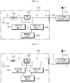
- FIGS. 1 and 2 are configuration diagrams of a relay testing apparatus according to the related art, respectively before and after a short circuit.
- a relay testing apparatus 10 will be described with reference to FIGS. 1 and 2 .
- a power supply 11 and an external apparatus 15 are connected via a power line, and a relay 14 is mounted on the power line.
- a voltage sensor 12 measuring a voltage difference between both ends of the relay 14 is mounted at both ends of the relay 14.
- an operating state of the relay 14 is controlled via a control unit 13, and the relay 14 is diagnosed based on a voltage difference at both ends measured using the voltage sensor 12 based on the operating state of the relay 14.
- KR 20130088800 A Prior art is disclosed in KR 20130088800 A .
- the present disclosure is designed to solve the problems of the related art, and therefore it is an object of the present disclosure to provide an apparatus for preventing damages in a circuit configuration caused by a short circuit.
- a short circuit occurring in an input/output terminal connected to an external apparatus may be prevented by changing a set resistance value of a variable resistor unit on an internal power line electrically connected to the input/output terminal.
- a configuration comprising a load apparatus and an apparatus for preventing a short circuit
- an input/output terminal unit configured to be electrically connected, via a second external power line, to an external apparatus that is electrically connected to one of a driving voltage supply and a ground via a first external power line
- an internal power line configured to electrically connect one of the driving voltage supply and the ground to the input/output terminal unit
- a switching unit configured to be mounted on the internal power line, the switching unit having one end electrically connected to the input/output terminal unit and configured to energize or block the internal power line
- a variable resistor unit configured to be mounted on the internal power line and configured to be electrically connected to the other end of the switching unit
- a control unit configured to determine whether the input/output terminal unit is shorted based on a measurement current value of a current flowing through the internal power line and control a set resistance value of the variable resistor unit in accordance with a result of the determination whether the input/output terminal unit is short
- the control unit determines that the input/output terminal unit is shorted.
- the control unit controls a set resistance value of the variable resistor unit to be a preset reference resistance value.
- the control unit may determine that the input/output terminal unit is shorted from another ground different from the ground connected to the external apparatus.
- control unit may determine whether an operating state of the switching unit is any one operating state of a turned-on state and a turned-off state based on a measurement voltage difference between a first measurement voltage value of one end voltage applied to one end of the switching unit and a second measurement voltage value of the other end voltage applied to the other end of the switching unit.
- the control unit may determine whether the input/output terminal unit is shorted, and control a set resistance value of the variable resistor unit in accordance with a result of the determination whether the input/output terminal unit is shorted.
- the control unit may not determine whether the input/output terminal unit is shorted.
- a battery pack according to the present disclosure may include the apparatus for preventing short circuit.
- a vehicle according to the present disclosure may include the apparatus for preventing short circuit.
- the short circuit when a short circuit occurs in an input/output terminal connected to an external apparatus, the short circuit is blocked by changing a set resistance value of a variable resistor unit on an internal power line electrically connected to the input/output terminal, thereby preventing a high current from flowing through the internal power line and an output of a driving voltage supply from exceeding an output limit.
- control unit denotes a unit of processing at least one function or operation, and may be embodied via hardware, software, or a combination of hardware and software.
- An apparatus for preventing a short circuit according to the present disclosure is electrically connected, via a second external power line, to an external apparatus that is electrically connected to one of a driving voltage supply and a ground via a first external power line.
- the driving voltage supply and the ground are a driving voltage supply and a ground that are located outside the apparatus for preventing a short circuit according to the present disclosure.
- the apparatus for preventing a short circuit includes an input/output terminal unit electrically connected to an external apparatus via a second external power line.
- the apparatus for preventing short circuit according to the present disclosure includes an internal power line that electrically connects one of the driving voltage supply and the ground included therein to the input/output terminal unit.
- An apparatus for preventing a short circuit 100 is electrically connected, via a second external power line OL2, to an external apparatus 1 that is electrically connected to a ground GND via a first external power line OL1.
- the apparatus for preventing a short circuit 100 includes an internal power line IL connecting a driving voltage supply Vo included therein to the input/output terminal unit 110.
- FIG. 3 illustrates a configuration of the apparatus for preventing a short circuit 100 according to an embodiment of the present disclosure, before a short circuit
- FIG. 4 illustrates a configuration of the apparatus for preventing short circuit 100 according to an embodiment of the present disclosure, after a short circuit.
- the apparatus for preventing short circuit 100 includes an input/output terminal unit 110, an internal power line IL, a switching unit 120, a variable resistor unit 130, a sensing unit 140, a memory unit 150, and a control unit 160.
- the apparatus for preventing short circuit 100 according to an embodiment of the present disclosure further includes a driving voltage supply Vo therein.
- the input/output terminal unit 110 is electrically connected, via a second external power line OL2, to an external apparatus 1 that is electrically connected to the ground GND via a first external power line OL1.
- the input/output terminal unit 110 acts as an output terminal outputting a driving voltage of the driving voltage supply Vo to the external apparatus 1.
- the internal power line IL electrically connects the driving voltage supply Vo provided therein to the input/output terminal unit 110.
- a driving voltage of the driving voltage supply Vo is applied to the input/output terminal unit 110 via the internal power line IL.
- the switching unit 120 is mounted on the internal power line IL and electrically connected to the input/output terminal unit 110. Accordingly, as an operating state of the switching unit 120 is controlled to be turned on or turned off, thereby energizing or blocking the internal power line IL.
- a driving voltage of the driving voltage supply Vo is applied to the input/output terminal unit 110. Accordingly, the input/output terminal unit 110 outputs a driving voltage to the external apparatus 1, thereby driving the external apparatus 1.
- the switching unit 120 may be a field-effect transistor (FET) device, and the external apparatus 1 may be an actuator.
- FET field-effect transistor
- the apparatus for preventing a short circuit 100 according to the present disclosure may be provided inside a vehicle and connected to an actuator.
- variable resistor unit 130 is mounted on the internal power line IL and electrically connected to the other end of the switching unit 120. That is, the variable resistor unit 130 is electrically connected between the driving voltage supply Vo and the switching unit 120, and is serially connected to the switching unit 120.
- variable resistor unit 130 may be modified according to control by the control unit 160 which will be described later.
- the variable resistor unit 130 may be a digital potentiometer, a resistance value of which is changed in accordance with an input value input from the control unit 160.
- variable resistor unit 130 is described to be a digital potentiometer, it should be noted that the type of the variable resistor unit 130 is not limited as long as a set resistance value is modifiable by the control of the control unit 160.
- the sensing unit 140 is operably coupled to the control unit 160 which will be described later. That is, the sensing unit 140 is coupled to the control unit 160 such that the sensing unit 140 transmits an electrical signal to the control unit 160 or receives an electrical signal from the control unit 160.
- the sensing unit 140 measures, for each preset cycle, one end voltage applied to one end of the switching unit 120 and the other end voltage applied to the other end of the switching unit 120.
- the sensing unit 140 measures a current flowing through the internal power line IL on each preset cycle.
- the sensing unit 140 as above may provide measurement signals respectively indicating the measured one end voltage, the measured other end voltage, and the measured current to the control unit 160.
- the sensing unit 140 may include a voltage sensor configured to measure a voltage.
- the sensing unit 140 may further include a current sensor configured to measure a current.
- the control unit 160 determines a first measurement voltage value, a second measurement voltage value, and a measurement current value respectively as the measured one end voltage, the measured other end voltage, and the measured current, through signal processing, and stores the voltage values in the memory unit 150.
- the memory unit 150 is a semiconductor memory device, and writes, erases or updates data generated using the control unit 160, determining whether the input/output terminal unit 110 is shorted, and stores a plurality of program codes provided to control a set resistance value of the variable resistor unit 130.
- the memory unit 150 may store preset setting values of various preset parameters used in implementing the present disclosure.
- the memory unit 150 may be a semiconductor memory device of any type as long as the memory unit 150 is a semiconductor memory device known to write, erase or update data.
- the memory unit 150 may be a DRAM, an SDRAM, a flash memory, a ROM, an EEPROM, a register, or the like.
- the memory unit 150 may further include a storage medium storing program codes in which control logic of the control unit 160 is defined.
- the storage medium includes a non-volatile memory device such as a flash memory or a hard disk.
- the memory unit 150 may be physically separated from the control unit 160 or may be integrated to the control unit 160.
- the control unit 160 may determine whether the input/output terminal unit 110 is shorted, based on a measurement current value of a current flowing through the internal power line IL, and may control a set resistance value of the variable resistor unit 130 in accordance with a result of the determination of a short circuit.
- control unit 160 determines that the input/output terminal unit 110 is shorted.
- the control unit 160 determines that the input/output terminal unit 110 is shorted from another ground GND' different from the ground GND connected to the external apparatus 1.
- a preset reference current value may be a current value, which is a reference for determining whether the input/output terminal unit 110 is shorted, and when the input/output terminal unit 110 is shorted, the preset reference current value is a minimum current value of a current that flows through the internal power line IL.
- the preset reference current value may be "1A".
- another ground GND' may be a chassis or a frame of a vehicle.
- the internal power line IL may be changed to a nonloaded circuit state, and thus a high current may flow therethrough. Accordingly, an output of the driving voltage supply Vo may exceed an output limit, and shutdown of the apparatus for preventing short circuit 100 and the entire electrical system of the vehicle including the apparatus for preventing short circuit 100 may occur.
- a short circuit of the input/output terminal unit 110 may result from an external impact due to a collision of a vehicle, incorrect connection of circuits or the like.
- control unit 160 controls a set resistance value of the variable resistor unit 130 to be a preset reference resistance value.
- control unit 160 controls a set resistance value of the variable resistor unit 130 to be a preset reference resistance value such that the internal power line IL is not changed to a nonloaded circuit state and no high current flows.
- the preset reference resistance value may be limited such that a voltage applied to the external apparatus 1 is included in a voltage range in which the external apparatus 1 is drivable.
- the preset reference voltage value may be "1 ⁇ ".
- the control unit 160 controls a set resistance value of the variable resistor unit 130 mounted on the internal power line IL to be a preset reference resistance value, thereby preventing a high current flowing through the internal power line IL and thus preventing output of the driving voltage supply Vo from exceeding the output limit.
- control unit 160 controls a set resistance value of the variable resistor unit 130 to be at "0 ⁇ ".
- control unit 160 controls a set resistance value of the variable resistor unit 130 to be at "0 ⁇ ", thereby preventing unnecessary voltage drop occurring in the variable resistor unit 130.
- control unit 160 determines an operating state of the switching unit 120, and determines or does not determine whether the input/output terminal unit 110 is shorted, based on a result of the determination of the operating state of the switching unit 120.
- control unit 160 determines whether an operating state of the switching unit 120 is a turned-on state or a turned-off state based on a measurement voltage difference between a first measurement voltage value of one end voltage applied to one end of the switching unit 120 and a second measurement voltage value of the other end voltage applied to the other end of the switching unit 120.
- the control unit 160 determines that the operating state of the switching unit 120 is a turned-on state, and when the measurement voltage difference exceeds the preset reference voltage difference, the control unit 160 determines that the operating state of the switching unit 120 is a turned-off state.
- the preset reference voltage difference may be a voltage value used as a reference for determining an operating state of the switching unit 120.
- the preset reference voltage difference may be half of a driving voltage of the driving voltage supply Vo.
- the preset reference voltage difference may be "6V".
- the control unit 160 determines whether the input/output terminal unit 110 is shorted, and controls a set resistance value of the variable resistor unit 130 based on a result of the determination.
- the control unit 160 omits determining whether the input/output terminal unit 110 is shorted.
- the control unit 160 may not determine whether the input/output terminal unit 110 is shorted.
- the control unit 160 may selectively include an application-specific integrated circuit (ASIC), another chip set, a logic circuit, a register, a communication modem, a data processing apparatus, or the like known in the art to execute various control logics. At least one of the various control logics executable by the control unit 160 may be combined, and the combined control logics may be written as a computer readable code system and listed in a computer readable recording medium.
- a recording medium type is not specifically limited as long as the recording medium is accessible by the control unit 160 included in a computer.
- a recording medium includes at least one selected from the group consisting of ROM, RAM, a register, CD-ROM, a magnetic tape, a hard disk, a floppy disk, and an optical data recording apparatus.
- a code system may be modulated with a carrier signal and included in a communication carrier at a certain point in time, and distributed and stored in a network-connected computer and executed.
- functional programs, codes, and code segments for implementing the combined control logics may be easily inferred by programmers skilled in the art to which the present disclosure pertains.
- the apparatus for preventing short circuit 100' according to another embodiment of the present disclosure is different from the apparatus for preventing a short circuit 100 according to an embodiment only in terms of electrical connection of some components. Thus, repeated description will be omitted.
- FIG. 5 illustrates a configuration of the apparatus for preventing short circuit 100' according to another embodiment of the present disclosure, before a short circuit
- FIG. 6 illustrates a configuration of the apparatus for preventing a short circuit 100' according to another embodiment of the present disclosure, after a short circuit.
- the apparatus for preventing short circuit 100' includes an input/output terminal unit 110, an internal power line IL, a switching unit 120, a variable resistor unit 130, a sensing unit 140, a memory unit 150, and a control unit 160.
- the apparatus for preventing short circuit 100' according to another embodiment of the present disclosure further includes a ground GND therein.
- the input/output terminal unit 110 is electrically connected, via a second external power line OL2, to an external apparatus 1 that is electrically connected to a driving voltage supply Vo outside via a first external power line OL1.
- the internal power line IL electrically connects the ground GND provided inside to the input/output terminal unit 110.
- a driving voltage of the driving voltage supply Vo dropped due to a resistance component of the external apparatus 1 is applied to the input/output terminal unit 110 via the internal power line IL.
- the switching unit 120 is mounted on the internal power line IL and electrically connected to the input/output terminal unit 110. Accordingly, as an operating state of the switching unit 120 is controlled to be in a turned-on or turned-off state, the internal power line IL may be energized or blocked.
- variable resistor unit 130 is mounted on the internal power line IL and electrically connected to the other end of the switching unit 120. That is, the variable resistor unit 130 is electrically connected between the driving voltage supply Vo and the switching unit 120, and is serially connected to the switching unit 120.
- a set resistance value of the variable resistor unit 130 may be modified according to the control by the control unit 160 which will be described later.
- the sensing unit 140 is operably coupled to the control unit 160 which will be described later. That is, the sensing unit 140 may be coupled to the control unit 160 such that the sensing unit 140 may transmit an electrical signal to the control unit 160 or receive an electrical signal from the control unit 160.
- the sensing unit 140 measures, in each preset cycle, one end voltage applied to one end of the switching unit 120 and the other end voltage applied to the other end of the switching unit 120.
- the sensing unit 140 may measure a current flowing through the internal power line IL in each preset cycle.
- the sensing unit 140 as above provides measurement signals respectively indicating the measured one end voltage, the measured other end voltage, and the measured current, to the control unit 160.
- the control unit 160 determines a first measurement voltage value, a second measurement voltage value, and a measurement current value respectively as the measured one end voltage, the measured other end voltage, and the measured current, through signal processing, and stores the same in the memory unit 150.
- the memory unit 150 is a semiconductor memory device, and writes, erases or updates data generated using the control unit 160, determining whether the input/output terminal unit 110 is shorted, and stores a plurality of program codes provided to control a set resistance value of the variable resistor unit 130.
- the memory unit 150 stores preset setting values of various preset parameters used in implementing the present disclosure.
- the control unit 160 determines whether the input/output terminal unit 110 is shorted, based on a measurement current value of a current flowing through the internal power line IL, and controls a set resistance value of the variable resistor unit 130 in accordance with a result of the determination of a short circuit.
- control unit 160 determines that the input/output terminal unit 110 is shorted.
- the control unit 160 determines that the input/output terminal unit 110 is shorted from the driving voltage supply Vo located outside.
- the internal power line IL may be changed to a nonloaded circuit state, and thus a high current may flow. Accordingly, an output of the driving voltage supply Vo may exceed an output limit, and shutdown of the apparatus for preventing short circuit 100' and the entire electrical system of a vehicle including the apparatus for preventing short circuit 100' may occur.
- a short circuit of the input/output terminal unit 110 may result from an external impact caused by collision of the vehicle or incorrect connection of circuits, or the like.
- the control unit 160 controls a set resistance value of the variable resistor unit 130 to be a preset reference resistance value.
- control unit 160 controls a set resistance value of the variable resistor unit 130 to be a preset reference resistance value such that the internal power line IL is not changed to a nonloaded circuit state and no high current flows.
- the control unit 160 controls a set resistance value of the variable resistor unit 130 mounted on the internal power line IL to be a preset reference resistance value, thereby preventing a high current flowing through the input/output terminal unit 110 and an output of the driving voltage supply Vo from exceeding an output limit.
- control unit 160 may control a set resistance value of the variable resistor unit 130 to be "0 ⁇ ".
- control unit 160 controls a set resistance value of the variable resistor unit 130 to be "0 ⁇ ", thereby preventing unnecessary voltage drop occurring in the variable resistor unit 130.
- a battery pack according to the present disclosure includes the above-described apparatus for preventing short circuit.
- a vehicle according to the present disclosure includes the above-described apparatus for preventing short circuit.
- Embodiments of the present disclosure described above are not embodied only through an apparatus, but may be embodied through a program realizing a function corresponding to a feature of the embodiments of the present disclosure or a recording medium having recorded thereon the program, and such embodiments may be easily embodied by experts of technical fields to which the present disclosure belongs, from the description of the embodiments described above.
Landscapes
- Physics & Mathematics (AREA)
- General Physics & Mathematics (AREA)
- Engineering & Computer Science (AREA)
- Power Engineering (AREA)
- Mechanical Engineering (AREA)
- Chemical & Material Sciences (AREA)
- Combustion & Propulsion (AREA)
- Protection Of Static Devices (AREA)
- Emergency Protection Circuit Devices (AREA)
- Testing Of Short-Circuits, Discontinuities, Leakage, Or Incorrect Line Connections (AREA)
Claims (7)
- Configuration comprenant un appareil de charge (1) et un appareil (100) pour éviter un court-circuit comprenant :une unité à borne d'entrée/sortie (110) configurée pour être électriquement connectée, via une deuxième ligne d'alimentation électrique externe (OL2), à un appareil de charge (1) qui peut être électriquement connecté à l'une parmi une alimentation en tension d'excitation (Vo) et une masse (GND) via une première ligne d'alimentation électrique externe (OL1) ;une ligne d'alimentation électrique interne (IL) configurée pour électriquement connecter l'une parmi l'alimentation en tension d'excitation (Vo) et la masse (GND) à l'unité à borne d'entrée/sortie (110) ;une unité de commutation (120) configurée pour être montée sur la ligne d'alimentation électrique interne (IL), l'unité de commutation (120) ayant une extrémité électriquement connectée à l'unité à borne d'entrée/sortie (110) et configurée pour alimenter ou bloquer la ligne d'alimentation électrique interne (IL) ;une unité à résistance variable (130) configurée pour être montée sur la ligne d'alimentation électrique interne (IL) et configurée pour être électriquement connectée à l'autre extrémité de l'unité de commutation (120) ; etcaractérisée parune unité de commande (160) configurée pour déterminer si l'unité à borne d'entrée/sortie (110) est court-circuitée sur la base d'une valeur de courant de mesure d'un courant circulant à travers la ligne d'alimentation électrique interne (IL) et commander une valeur de résistance définie de l'unité à résistance variable (130) conformément à un résultat de la détermination que l'unité à borne d'entrée/sortie (110) est court-circuitée,dans laquelle, quand la valeur de courant de mesure dépasse une valeur de courant de référence prédéfinie, l'unité de commande (160) détermine que l'unité à borne d'entrée/sortie (110) est court-circuitée, etdans laquelle, quand il est déterminé que l'unité à borne d'entrée/sortie (110) est court-circuitée suite à la détermination que l'unité à borne d'entrée/sortie (110) est court-circuitée, l'unité de commande (160) commande une valeur de résistance définie de l'unité à résistance variable (130) pour qu'elle soit une valeur de résistance de référence prédéfinie.
- Configuration selon la revendication 1, dans laquelle, quand la masse (GND) et l'appareil de charge (1) sont électriquement connectés via la première ligne d'alimentation électrique externe (OL1), l'alimentation en tension d'excitation (Vo) et l'unité à borne d'entrée/sortie (110) sont électriquement connectées via la ligne d'alimentation électrique interne (IL), et la valeur de courant de mesure dépasse une valeur de courant de référence prédéfinie, l'unité de commande (160) détermine que l'unité à borne d'entrée/sortie (110) est court-circuitée par rapport à une autre masse (GND') différente de la masse (GND) connectée à l'appareil de charge (1).
- Configuration selon la revendication 1, dans laquelle l'unité de commande (160) détermine si un état de fonctionnement de l'unité de commutation (120) est n'importe quel état de fonctionnement parmi un état activé et un état désactivé sur la base d'une différence de tension de mesure entre une première valeur de tension de mesure d'une tension d'extrémité appliquée à une extrémité de l'unité de commutation (120) et une deuxième valeur de tension de mesure de l'autre tension d'extrémité appliquée à l'autre extrémité de l'unité de commutation (120).
- Configuration selon la revendication 3, dans laquelle, quand l'unité de commutation est dans un état activé suite à la détermination de l'état de fonctionnement de l'unité de commutation (120), l'unité de commande (160) détermine si l'unité à borne d'entrée/sortie (110) est court-circuitée, et commande une valeur de résistance définie de l'unité à résistance variable (130) conformément à un résultat de la détermination que l'unité à borne d'entrée/sortie (110) est court-circuitée.
- Configuration selon la revendication 3, dans laquelle, quand l'unité de commutation (120) est dans un état désactivé suite à la détermination de l'état de fonctionnement de l'unité de commutation (120), l'unité de commande (160) ne détermine pas si l'unité à borne d'entrée/sortie (110) est court-circuitée.
- Bloc-batterie comprenant la configuration selon l'une quelconque des revendications 1 à 5.
- Véhicule comprenant la configuration selon l'une quelconque des revendications 1 à 5.
Applications Claiming Priority (2)
| Application Number | Priority Date | Filing Date | Title |
|---|---|---|---|
| KR1020170169306A KR102423301B1 (ko) | 2017-12-11 | 2017-12-11 | 단락 방지 장치 및 방법 |
| PCT/KR2018/015567 WO2019117555A1 (fr) | 2017-12-11 | 2018-12-07 | Dispositif et procédé de prévention de court-circuit |
Publications (3)
| Publication Number | Publication Date |
|---|---|
| EP3672006A1 EP3672006A1 (fr) | 2020-06-24 |
| EP3672006A4 EP3672006A4 (fr) | 2020-12-02 |
| EP3672006B1 true EP3672006B1 (fr) | 2023-02-01 |
Family
ID=66820462
Family Applications (1)
| Application Number | Title | Priority Date | Filing Date |
|---|---|---|---|
| EP18889917.3A Active EP3672006B1 (fr) | 2017-12-11 | 2018-12-07 | Dispositif et procédé de prévention de court-circuit |
Country Status (7)
| Country | Link |
|---|---|
| US (1) | US11269018B2 (fr) |
| EP (1) | EP3672006B1 (fr) |
| JP (1) | JP6973881B2 (fr) |
| KR (1) | KR102423301B1 (fr) |
| CN (1) | CN110741521B (fr) |
| PL (1) | PL3672006T3 (fr) |
| WO (1) | WO2019117555A1 (fr) |
Families Citing this family (6)
| Publication number | Priority date | Publication date | Assignee | Title |
|---|---|---|---|---|
| CN112092753A (zh) * | 2020-08-28 | 2020-12-18 | 广州亚美智造科技有限公司 | Obd设备供电电路及其控制方法、obd模拟器 |
| TWI777439B (zh) * | 2021-03-08 | 2022-09-11 | 廣達電腦股份有限公司 | 電流感測電路 |
| CN113400941B (zh) * | 2021-06-24 | 2022-09-02 | 中国第一汽车股份有限公司 | 一种主动短路信号处理电路及车辆 |
| CN114264976B (zh) * | 2022-01-13 | 2024-11-01 | 云南电网有限责任公司电力科学研究院 | 一种双抽头双边比电流互感器匝间短路检测系统及方法 |
| KR102801940B1 (ko) * | 2023-04-07 | 2025-04-30 | 에이치디현대일렉트릭 주식회사 | 접지저항 제어 시스템 및 접지저항 제어 방법 |
| WO2025258895A1 (fr) * | 2024-06-10 | 2025-12-18 | 삼성전자 주식회사 | Structure de ligne de transmission d'un support de charge et écouteur |
Family Cites Families (51)
| Publication number | Priority date | Publication date | Assignee | Title |
|---|---|---|---|---|
| US3916309A (en) * | 1974-09-30 | 1975-10-28 | S & C Electric Co | Short circuit capacity measuring device |
| US5689395A (en) * | 1995-09-14 | 1997-11-18 | Raychem Corporation | Overcurrent protection circuit |
| DE69739666D1 (de) * | 1996-07-16 | 2009-12-31 | Ewd L L C | Schutzschaltungsanordnungen |
| CN1080473C (zh) | 1996-07-16 | 2002-03-06 | 雷伊化学公司 | 电子保护系统和继电器组件 |
| US5926354A (en) * | 1997-06-11 | 1999-07-20 | International Rectifier Corporation | Solid state relay and circuit breaker |
| TW407212B (en) | 1997-10-31 | 2000-10-01 | Toshiba Battery | Battery remaining capacity measuring device |
| US6349022B1 (en) | 1998-09-18 | 2002-02-19 | Tyco Electronics Corporation | Latching protection circuit |
| US6285191B1 (en) * | 1999-10-08 | 2001-09-04 | Alliedsignal Inc. | Measurement of current in a vehicle using battery cable as a shunt |
| US7031132B1 (en) * | 2002-06-14 | 2006-04-18 | Mitchell Dennis A | Short circuit diagnostic tool |
| KR100508566B1 (ko) * | 2003-01-27 | 2005-08-17 | 주식회사 엘지화학 | 조립된 배터리 팩 상태에서의 보호 회로의 기능 검사 방법 |
| JP4396539B2 (ja) * | 2004-06-03 | 2010-01-13 | 株式会社デンソー | レアショート検出回路及び異常監視信号生成回路 |
| WO2006016456A1 (fr) * | 2004-08-10 | 2006-02-16 | Rohm Co., Ltd | Technique de protection des circuits, circuit de protection et bloc d’alimentation équipé du circuit de protection |
| KR100709258B1 (ko) | 2005-10-20 | 2007-04-19 | 삼성에스디아이 주식회사 | 배터리 관리 시스템 |
| KR100740097B1 (ko) | 2005-10-20 | 2007-07-16 | 삼성에스디아이 주식회사 | 배터리의 soc 추정 방법 및 이를 이용한 배터리 관리시스템 |
| FR2900241B1 (fr) * | 2006-04-21 | 2008-07-11 | Alstom Transport Sa | Procede de depistage d'un court-circuit resistif, systeme, module et support d'enregistrement pour ce procede |
| CN103441472B (zh) | 2009-04-21 | 2016-03-30 | 无锡中感微电子股份有限公司 | 一种电池保护电路 |
| JP5040041B2 (ja) | 2010-06-16 | 2012-10-03 | 三井金属アクト株式会社 | 車両用ドアの開閉制御装置 |
| JP2012013044A (ja) | 2010-07-02 | 2012-01-19 | Honda Motor Co Ltd | バッテリ制御システム |
| JP5124627B2 (ja) * | 2010-09-10 | 2013-01-23 | 株式会社日本自動車部品総合研究所 | センサの検知制御器および乗員検知装置 |
| CN102539990A (zh) * | 2010-12-28 | 2012-07-04 | 鸿富锦精密工业(深圳)有限公司 | 电容短路侦测电路 |
| JP5571594B2 (ja) * | 2011-01-27 | 2014-08-13 | コーセル株式会社 | スイッチング電源装置 |
| CN102928726A (zh) * | 2011-08-09 | 2013-02-13 | 鸿富锦精密工业(深圳)有限公司 | 短路检测电路 |
| JP5950591B2 (ja) * | 2012-01-31 | 2016-07-13 | エスアイアイ・セミコンダクタ株式会社 | ボルテージレギュレータ |
| KR101361085B1 (ko) * | 2012-02-01 | 2014-02-13 | 군산대학교산학협력단 | 사고 전류 제어 장치 및 방법 |
| KR101977968B1 (ko) * | 2012-03-14 | 2019-05-14 | 엘지디스플레이 주식회사 | 액정표시장치와 이의 구동방법 |
| KR101543059B1 (ko) * | 2012-11-09 | 2015-08-07 | 엘지이노텍 주식회사 | 무선전력 수신장치 및 그의 전력 제어 방법 |
| KR101373165B1 (ko) * | 2012-11-30 | 2014-03-11 | 주식회사 포스코 | 사이리스터 고장 검출 장치 및 검출 방법 |
| US9578728B2 (en) * | 2013-06-18 | 2017-02-21 | Dialight Corporation | Long life, fail safe traffic light |
| EP3036973B1 (fr) * | 2013-08-19 | 2018-01-03 | OLEDWorks GmbH | Circuit de détection de court-circuit pour circuit de commande à del et procédé de détection de court-circuit |
| JP5652562B1 (ja) * | 2013-09-19 | 2015-01-14 | 株式会社豊田自動織機 | Mosfetスイッチ素子の異常診断装置及び方法 |
| US9588148B2 (en) * | 2014-01-23 | 2017-03-07 | Veris Industries, Llc | Input circuit for current transformer |
| WO2015194223A1 (fr) | 2014-06-20 | 2015-12-23 | オリンパス株式会社 | Dispositif de commande d'actionneur |
| WO2016003666A2 (fr) * | 2014-06-30 | 2016-01-07 | Medtronic, Inc. | Identification d'une brèche d'isolation à l'aide d'électrogrammes |
| KR102233719B1 (ko) * | 2014-10-31 | 2021-03-30 | 엘지디스플레이 주식회사 | 유기 발광 다이오드 표시 장치 및 그 구동 방법 |
| JP2016115283A (ja) | 2014-12-17 | 2016-06-23 | 株式会社東芝 | 電流電圧抑制装置 |
| JP6492672B2 (ja) * | 2015-01-14 | 2019-04-03 | 株式会社デンソー | 負荷駆動装置 |
| KR101646070B1 (ko) * | 2015-03-04 | 2016-08-05 | 두산중공업 주식회사 | 단락 고장 검출 회로 |
| US9647444B2 (en) * | 2015-06-16 | 2017-05-09 | Hamilton Sundstrand Corporation | Variable threshold current limiting circuit |
| KR20170005910A (ko) * | 2015-07-06 | 2017-01-17 | 주식회사 만도 | 전동식 조향장치의 모터 구동제어회로 |
| RU2602994C1 (ru) * | 2015-09-21 | 2016-11-20 | федеральное государственное автономное образовательное учреждение высшего образования "Южный федеральный университет" | Устройство контроля электрических параметров пиросредств |
| US10538165B2 (en) * | 2015-09-22 | 2020-01-21 | Ford Global Technologies, Llc | Parameter estimation of loosely coupled transformer |
| CN105514944A (zh) * | 2016-01-28 | 2016-04-20 | 杰华特微电子(张家港)有限公司 | 一种电源保护电路及方法 |
| CN108027400B (zh) * | 2016-04-28 | 2019-11-29 | 华为技术有限公司 | 防短路检测装置及用户终端 |
| JP6829947B2 (ja) * | 2016-05-17 | 2021-02-17 | ローム株式会社 | 発光素子駆動用半導体集積回路、発光素子駆動装置、発光装置、車両 |
| CN106526404B (zh) * | 2016-12-09 | 2022-12-30 | 成都信息工程大学 | 一种短路、漏电检测装置及其检测方法 |
| JP6961944B2 (ja) * | 2017-01-18 | 2021-11-05 | 富士電機株式会社 | パワー半導体モジュール |
| CN107390147B (zh) * | 2017-08-09 | 2020-05-15 | 上海联影医疗科技有限公司 | 一种局部线圈的调失谐系统的故障诊断电路及方法 |
| DE102017214205A1 (de) * | 2017-08-15 | 2019-02-21 | Robert Bosch Gmbh | Steuergerät mit Schaltung und Verfahren zum Kurzschlussschutz von Masseleitungen und Sensoren |
| TWI649573B (zh) * | 2017-12-04 | 2019-02-01 | 財團法人工業技術研究院 | 電池內短路阻抗之偵測方法和系統 |
| JP6946990B2 (ja) * | 2017-12-06 | 2021-10-13 | 株式会社デンソー | 信号出力装置 |
| CN112186721B (zh) * | 2020-09-30 | 2021-06-04 | 江苏卫川物联科技有限公司 | 电气防火限流式保护器 |
-
2017
- 2017-12-11 KR KR1020170169306A patent/KR102423301B1/ko active Active
-
2018
- 2018-12-07 JP JP2019565225A patent/JP6973881B2/ja active Active
- 2018-12-07 WO PCT/KR2018/015567 patent/WO2019117555A1/fr not_active Ceased
- 2018-12-07 PL PL18889917.3T patent/PL3672006T3/pl unknown
- 2018-12-07 EP EP18889917.3A patent/EP3672006B1/fr active Active
- 2018-12-07 CN CN201880038387.6A patent/CN110741521B/zh active Active
- 2018-12-07 US US16/615,577 patent/US11269018B2/en active Active
Also Published As
| Publication number | Publication date |
|---|---|
| EP3672006A4 (fr) | 2020-12-02 |
| WO2019117555A1 (fr) | 2019-06-20 |
| CN110741521A (zh) | 2020-01-31 |
| JP6973881B2 (ja) | 2021-12-01 |
| KR102423301B1 (ko) | 2022-07-19 |
| US20200081052A1 (en) | 2020-03-12 |
| KR20190068998A (ko) | 2019-06-19 |
| JP2020522218A (ja) | 2020-07-27 |
| PL3672006T3 (pl) | 2023-04-11 |
| EP3672006A1 (fr) | 2020-06-24 |
| US11269018B2 (en) | 2022-03-08 |
| CN110741521B (zh) | 2021-12-21 |
Similar Documents
| Publication | Publication Date | Title |
|---|---|---|
| EP3672006B1 (fr) | Dispositif et procédé de prévention de court-circuit | |
| CN111670368B (zh) | 开关诊断设备和方法、含该设备的电池管理系统和电池组 | |
| US10753975B2 (en) | Apparatus for diagnosing relay failure of battery using parallel circuit for constant power supply and method thereof | |
| US11936176B2 (en) | Contactor, an integrated circuit, a method of interrupting a current flow | |
| EP3674725A1 (fr) | Dispositif de diagnostic de circuit d'attaque de relais | |
| US10725115B2 (en) | Methods and apparatus for detecting electrical leakage in a vehicle | |
| US9800042B2 (en) | Electrical load controller with fault detection | |
| CN105445525A (zh) | 在具有霍尔传感器的电流传感器中的过电流识别 | |
| CN109842295A (zh) | 负载驱动电路 | |
| EP3982136A1 (fr) | Procédé de détection d'anomalies dans une unité de commutation de charge, et système de batterie l'utilisant | |
| EP2306650A2 (fr) | Convertisseur analogique/numérique et son procédé de détection ouverte | |
| US9739823B2 (en) | Diagnostic circuit and method for the operation of a diagnostic circuit | |
| CN108362969B (zh) | 识别连接在电路端子上的负载的状态的方法和电路装置 | |
| US20170357517A1 (en) | Switch state determining device | |
| US20200371149A1 (en) | Method for checking an output stage for controlling a load | |
| JP2018045583A (ja) | 信号処理装置 | |
| US20180301888A1 (en) | Highly Variable and Adjustable Current Circuit Breaker | |
| US11232653B2 (en) | Smart vehicle system | |
| US11940469B2 (en) | Circuit system for measuring an electrical voltage | |
| JP2007019293A (ja) | リニアソレノイドの駆動装置 | |
| JP3289620B2 (ja) | エアバッグシステム及びその診断方法 | |
| JP5281501B2 (ja) | 物理量センサ | |
| CN112272965A (zh) | 用于电负载的电路和诊断方法 | |
| US20250286390A1 (en) | Battery management system | |
| US20230408560A1 (en) | Contactor, an integrated circuit, a method of interrupting a current flow |
Legal Events
| Date | Code | Title | Description |
|---|---|---|---|
| STAA | Information on the status of an ep patent application or granted ep patent |
Free format text: STATUS: THE INTERNATIONAL PUBLICATION HAS BEEN MADE |
|
| PUAI | Public reference made under article 153(3) epc to a published international application that has entered the european phase |
Free format text: ORIGINAL CODE: 0009012 |
|
| STAA | Information on the status of an ep patent application or granted ep patent |
Free format text: STATUS: REQUEST FOR EXAMINATION WAS MADE |
|
| 17P | Request for examination filed |
Effective date: 20200318 |
|
| AK | Designated contracting states |
Kind code of ref document: A1 Designated state(s): AL AT BE BG CH CY CZ DE DK EE ES FI FR GB GR HR HU IE IS IT LI LT LU LV MC MK MT NL NO PL PT RO RS SE SI SK SM TR |
|
| AX | Request for extension of the european patent |
Extension state: BA ME |
|
| RIN1 | Information on inventor provided before grant (corrected) |
Inventor name: CHOI, JIN-HWEE |
|
| REG | Reference to a national code |
Ref country code: DE Ref legal event code: R079 Ref document number: 602018045953 Country of ref document: DE Free format text: PREVIOUS MAIN CLASS: H02H0003087000 Ipc: H02H0009020000 |
|
| A4 | Supplementary search report drawn up and despatched |
Effective date: 20201029 |
|
| RIC1 | Information provided on ipc code assigned before grant |
Ipc: G01R 19/165 20060101ALI20201023BHEP Ipc: B60R 16/03 20060101ALI20201023BHEP Ipc: H02H 9/02 20060101AFI20201023BHEP Ipc: G01R 31/327 20060101ALI20201023BHEP Ipc: G01R 31/52 20200101ALI20201023BHEP Ipc: H02H 3/087 20060101ALI20201023BHEP |
|
| DAV | Request for validation of the european patent (deleted) | ||
| DAX | Request for extension of the european patent (deleted) | ||
| RAP1 | Party data changed (applicant data changed or rights of an application transferred) |
Owner name: LG ENERGY SOLUTION LTD. |
|
| RAP3 | Party data changed (applicant data changed or rights of an application transferred) |
Owner name: LG ENERGY SOLUTION, LTD. |
|
| GRAP | Despatch of communication of intention to grant a patent |
Free format text: ORIGINAL CODE: EPIDOSNIGR1 |
|
| STAA | Information on the status of an ep patent application or granted ep patent |
Free format text: STATUS: GRANT OF PATENT IS INTENDED |
|
| INTG | Intention to grant announced |
Effective date: 20220811 |
|
| GRAS | Grant fee paid |
Free format text: ORIGINAL CODE: EPIDOSNIGR3 |
|
| GRAA | (expected) grant |
Free format text: ORIGINAL CODE: 0009210 |
|
| STAA | Information on the status of an ep patent application or granted ep patent |
Free format text: STATUS: THE PATENT HAS BEEN GRANTED |
|
| AK | Designated contracting states |
Kind code of ref document: B1 Designated state(s): AL AT BE BG CH CY CZ DE DK EE ES FI FR GB GR HR HU IE IS IT LI LT LU LV MC MK MT NL NO PL PT RO RS SE SI SK SM TR |
|
| REG | Reference to a national code |
Ref country code: GB Ref legal event code: FG4D |
|
| REG | Reference to a national code |
Ref country code: CH Ref legal event code: EP Ref country code: AT Ref legal event code: REF Ref document number: 1547173 Country of ref document: AT Kind code of ref document: T Effective date: 20230215 |
|
| REG | Reference to a national code |
Ref country code: DE Ref legal event code: R096 Ref document number: 602018045953 Country of ref document: DE |
|
| REG | Reference to a national code |
Ref country code: IE Ref legal event code: FG4D |
|
| REG | Reference to a national code |
Ref country code: SE Ref legal event code: TRGR |
|
| REG | Reference to a national code |
Ref country code: LT Ref legal event code: MG9D |
|
| REG | Reference to a national code |
Ref country code: NL Ref legal event code: MP Effective date: 20230201 |
|
| P01 | Opt-out of the competence of the unified patent court (upc) registered |
Effective date: 20230525 |
|
| REG | Reference to a national code |
Ref country code: AT Ref legal event code: MK05 Ref document number: 1547173 Country of ref document: AT Kind code of ref document: T Effective date: 20230201 |
|
| PG25 | Lapsed in a contracting state [announced via postgrant information from national office to epo] |
Ref country code: RS Free format text: LAPSE BECAUSE OF FAILURE TO SUBMIT A TRANSLATION OF THE DESCRIPTION OR TO PAY THE FEE WITHIN THE PRESCRIBED TIME-LIMIT Effective date: 20230201 Ref country code: PT Free format text: LAPSE BECAUSE OF FAILURE TO SUBMIT A TRANSLATION OF THE DESCRIPTION OR TO PAY THE FEE WITHIN THE PRESCRIBED TIME-LIMIT Effective date: 20230601 Ref country code: NO Free format text: LAPSE BECAUSE OF FAILURE TO SUBMIT A TRANSLATION OF THE DESCRIPTION OR TO PAY THE FEE WITHIN THE PRESCRIBED TIME-LIMIT Effective date: 20230501 Ref country code: NL Free format text: LAPSE BECAUSE OF FAILURE TO SUBMIT A TRANSLATION OF THE DESCRIPTION OR TO PAY THE FEE WITHIN THE PRESCRIBED TIME-LIMIT Effective date: 20230201 Ref country code: LV Free format text: LAPSE BECAUSE OF FAILURE TO SUBMIT A TRANSLATION OF THE DESCRIPTION OR TO PAY THE FEE WITHIN THE PRESCRIBED TIME-LIMIT Effective date: 20230201 Ref country code: LT Free format text: LAPSE BECAUSE OF FAILURE TO SUBMIT A TRANSLATION OF THE DESCRIPTION OR TO PAY THE FEE WITHIN THE PRESCRIBED TIME-LIMIT Effective date: 20230201 Ref country code: HR Free format text: LAPSE BECAUSE OF FAILURE TO SUBMIT A TRANSLATION OF THE DESCRIPTION OR TO PAY THE FEE WITHIN THE PRESCRIBED TIME-LIMIT Effective date: 20230201 Ref country code: ES Free format text: LAPSE BECAUSE OF FAILURE TO SUBMIT A TRANSLATION OF THE DESCRIPTION OR TO PAY THE FEE WITHIN THE PRESCRIBED TIME-LIMIT Effective date: 20230201 Ref country code: AT Free format text: LAPSE BECAUSE OF FAILURE TO SUBMIT A TRANSLATION OF THE DESCRIPTION OR TO PAY THE FEE WITHIN THE PRESCRIBED TIME-LIMIT Effective date: 20230201 |
|
| PG25 | Lapsed in a contracting state [announced via postgrant information from national office to epo] |
Ref country code: IS Free format text: LAPSE BECAUSE OF FAILURE TO SUBMIT A TRANSLATION OF THE DESCRIPTION OR TO PAY THE FEE WITHIN THE PRESCRIBED TIME-LIMIT Effective date: 20230601 Ref country code: GR Free format text: LAPSE BECAUSE OF FAILURE TO SUBMIT A TRANSLATION OF THE DESCRIPTION OR TO PAY THE FEE WITHIN THE PRESCRIBED TIME-LIMIT Effective date: 20230502 Ref country code: FI Free format text: LAPSE BECAUSE OF FAILURE TO SUBMIT A TRANSLATION OF THE DESCRIPTION OR TO PAY THE FEE WITHIN THE PRESCRIBED TIME-LIMIT Effective date: 20230201 |
|
| PG25 | Lapsed in a contracting state [announced via postgrant information from national office to epo] |
Ref country code: SM Free format text: LAPSE BECAUSE OF FAILURE TO SUBMIT A TRANSLATION OF THE DESCRIPTION OR TO PAY THE FEE WITHIN THE PRESCRIBED TIME-LIMIT Effective date: 20230201 Ref country code: RO Free format text: LAPSE BECAUSE OF FAILURE TO SUBMIT A TRANSLATION OF THE DESCRIPTION OR TO PAY THE FEE WITHIN THE PRESCRIBED TIME-LIMIT Effective date: 20230201 Ref country code: EE Free format text: LAPSE BECAUSE OF FAILURE TO SUBMIT A TRANSLATION OF THE DESCRIPTION OR TO PAY THE FEE WITHIN THE PRESCRIBED TIME-LIMIT Effective date: 20230201 Ref country code: DK Free format text: LAPSE BECAUSE OF FAILURE TO SUBMIT A TRANSLATION OF THE DESCRIPTION OR TO PAY THE FEE WITHIN THE PRESCRIBED TIME-LIMIT Effective date: 20230201 Ref country code: CZ Free format text: LAPSE BECAUSE OF FAILURE TO SUBMIT A TRANSLATION OF THE DESCRIPTION OR TO PAY THE FEE WITHIN THE PRESCRIBED TIME-LIMIT Effective date: 20230201 |
|
| REG | Reference to a national code |
Ref country code: DE Ref legal event code: R097 Ref document number: 602018045953 Country of ref document: DE |
|
| PG25 | Lapsed in a contracting state [announced via postgrant information from national office to epo] |
Ref country code: SK Free format text: LAPSE BECAUSE OF FAILURE TO SUBMIT A TRANSLATION OF THE DESCRIPTION OR TO PAY THE FEE WITHIN THE PRESCRIBED TIME-LIMIT Effective date: 20230201 |
|
| PLBE | No opposition filed within time limit |
Free format text: ORIGINAL CODE: 0009261 |
|
| STAA | Information on the status of an ep patent application or granted ep patent |
Free format text: STATUS: NO OPPOSITION FILED WITHIN TIME LIMIT |
|
| 26N | No opposition filed |
Effective date: 20231103 |
|
| PG25 | Lapsed in a contracting state [announced via postgrant information from national office to epo] |
Ref country code: SI Free format text: LAPSE BECAUSE OF FAILURE TO SUBMIT A TRANSLATION OF THE DESCRIPTION OR TO PAY THE FEE WITHIN THE PRESCRIBED TIME-LIMIT Effective date: 20230201 |
|
| PG25 | Lapsed in a contracting state [announced via postgrant information from national office to epo] |
Ref country code: IT Free format text: LAPSE BECAUSE OF FAILURE TO SUBMIT A TRANSLATION OF THE DESCRIPTION OR TO PAY THE FEE WITHIN THE PRESCRIBED TIME-LIMIT Effective date: 20230201 |
|
| REG | Reference to a national code |
Ref country code: CH Ref legal event code: PL |
|
| PG25 | Lapsed in a contracting state [announced via postgrant information from national office to epo] |
Ref country code: LU Free format text: LAPSE BECAUSE OF NON-PAYMENT OF DUE FEES Effective date: 20231207 |
|
| PG25 | Lapsed in a contracting state [announced via postgrant information from national office to epo] |
Ref country code: MC Free format text: LAPSE BECAUSE OF FAILURE TO SUBMIT A TRANSLATION OF THE DESCRIPTION OR TO PAY THE FEE WITHIN THE PRESCRIBED TIME-LIMIT Effective date: 20230201 |
|
| REG | Reference to a national code |
Ref country code: BE Ref legal event code: MM Effective date: 20231231 |
|
| PG25 | Lapsed in a contracting state [announced via postgrant information from national office to epo] |
Ref country code: MC Free format text: LAPSE BECAUSE OF FAILURE TO SUBMIT A TRANSLATION OF THE DESCRIPTION OR TO PAY THE FEE WITHIN THE PRESCRIBED TIME-LIMIT Effective date: 20230201 Ref country code: LU Free format text: LAPSE BECAUSE OF NON-PAYMENT OF DUE FEES Effective date: 20231207 |
|
| REG | Reference to a national code |
Ref country code: IE Ref legal event code: MM4A |
|
| PG25 | Lapsed in a contracting state [announced via postgrant information from national office to epo] |
Ref country code: IE Free format text: LAPSE BECAUSE OF NON-PAYMENT OF DUE FEES Effective date: 20231207 |
|
| PG25 | Lapsed in a contracting state [announced via postgrant information from national office to epo] |
Ref country code: BE Free format text: LAPSE BECAUSE OF NON-PAYMENT OF DUE FEES Effective date: 20231231 |
|
| PG25 | Lapsed in a contracting state [announced via postgrant information from national office to epo] |
Ref country code: CH Free format text: LAPSE BECAUSE OF NON-PAYMENT OF DUE FEES Effective date: 20231231 |
|
| PG25 | Lapsed in a contracting state [announced via postgrant information from national office to epo] |
Ref country code: IE Free format text: LAPSE BECAUSE OF NON-PAYMENT OF DUE FEES Effective date: 20231207 Ref country code: CH Free format text: LAPSE BECAUSE OF NON-PAYMENT OF DUE FEES Effective date: 20231231 Ref country code: BE Free format text: LAPSE BECAUSE OF NON-PAYMENT OF DUE FEES Effective date: 20231231 |
|
| PG25 | Lapsed in a contracting state [announced via postgrant information from national office to epo] |
Ref country code: BG Free format text: LAPSE BECAUSE OF FAILURE TO SUBMIT A TRANSLATION OF THE DESCRIPTION OR TO PAY THE FEE WITHIN THE PRESCRIBED TIME-LIMIT Effective date: 20230201 |
|
| PG25 | Lapsed in a contracting state [announced via postgrant information from national office to epo] |
Ref country code: BG Free format text: LAPSE BECAUSE OF FAILURE TO SUBMIT A TRANSLATION OF THE DESCRIPTION OR TO PAY THE FEE WITHIN THE PRESCRIBED TIME-LIMIT Effective date: 20230201 |
|
| PG25 | Lapsed in a contracting state [announced via postgrant information from national office to epo] |
Ref country code: CY Free format text: LAPSE BECAUSE OF FAILURE TO SUBMIT A TRANSLATION OF THE DESCRIPTION OR TO PAY THE FEE WITHIN THE PRESCRIBED TIME-LIMIT; INVALID AB INITIO Effective date: 20181207 |
|
| PG25 | Lapsed in a contracting state [announced via postgrant information from national office to epo] |
Ref country code: HU Free format text: LAPSE BECAUSE OF FAILURE TO SUBMIT A TRANSLATION OF THE DESCRIPTION OR TO PAY THE FEE WITHIN THE PRESCRIBED TIME-LIMIT; INVALID AB INITIO Effective date: 20181207 |
|
| PG25 | Lapsed in a contracting state [announced via postgrant information from national office to epo] |
Ref country code: TR Free format text: LAPSE BECAUSE OF FAILURE TO SUBMIT A TRANSLATION OF THE DESCRIPTION OR TO PAY THE FEE WITHIN THE PRESCRIBED TIME-LIMIT Effective date: 20230201 |
|
| PGFP | Annual fee paid to national office [announced via postgrant information from national office to epo] |
Ref country code: DE Payment date: 20251120 Year of fee payment: 8 |
|
| PGFP | Annual fee paid to national office [announced via postgrant information from national office to epo] |
Ref country code: GB Payment date: 20251120 Year of fee payment: 8 |
|
| PGFP | Annual fee paid to national office [announced via postgrant information from national office to epo] |
Ref country code: FR Payment date: 20251125 Year of fee payment: 8 |
|
| PGFP | Annual fee paid to national office [announced via postgrant information from national office to epo] |
Ref country code: SE Payment date: 20251121 Year of fee payment: 8 |
|
| PGFP | Annual fee paid to national office [announced via postgrant information from national office to epo] |
Ref country code: PL Payment date: 20251125 Year of fee payment: 8 |