EP3672008B1 - Compensateur série et procédé de commande - Google Patents
Compensateur série et procédé de commande Download PDFInfo
- Publication number
- EP3672008B1 EP3672008B1 EP18891849.4A EP18891849A EP3672008B1 EP 3672008 B1 EP3672008 B1 EP 3672008B1 EP 18891849 A EP18891849 A EP 18891849A EP 3672008 B1 EP3672008 B1 EP 3672008B1
- Authority
- EP
- European Patent Office
- Prior art keywords
- series
- winding
- transformer
- bypass device
- speed
- Prior art date
- Legal status (The legal status is an assumption and is not a legal conclusion. Google has not performed a legal analysis and makes no representation as to the accuracy of the status listed.)
- Active
Links
Images

Classifications
-
- H—ELECTRICITY
- H02—GENERATION; CONVERSION OR DISTRIBUTION OF ELECTRIC POWER
- H02J—ELECTRIC POWER NETWORKS; CIRCUIT ARRANGEMENTS OR SYSTEMS FOR SUPPLYING OR DISTRIBUTING ELECTRIC POWER; SYSTEMS FOR STORING ELECTRIC ENERGY
- H02J3/00—Circuit arrangements for AC mains or AC distribution networks
-
- H—ELECTRICITY
- H02—GENERATION; CONVERSION OR DISTRIBUTION OF ELECTRIC POWER
- H02H—EMERGENCY PROTECTIVE CIRCUIT ARRANGEMENTS
- H02H9/00—Emergency protective circuit arrangements for limiting excess current or voltage without disconnection
- H02H9/02—Emergency protective circuit arrangements for limiting excess current or voltage without disconnection responsive to excess current
-
- H—ELECTRICITY
- H02—GENERATION; CONVERSION OR DISTRIBUTION OF ELECTRIC POWER
- H02J—ELECTRIC POWER NETWORKS; CIRCUIT ARRANGEMENTS OR SYSTEMS FOR SUPPLYING OR DISTRIBUTING ELECTRIC POWER; SYSTEMS FOR STORING ELECTRIC ENERGY
- H02J3/00—Circuit arrangements for AC mains or AC distribution networks
- H02J3/18—Arrangements for adjusting, eliminating or compensating reactive power in networks
- H02J3/1807—Arrangements for adjusting, eliminating or compensating reactive power in networks using series compensators, e.g. thyristor-controlled series capacitors [TCSC]
- H02J3/1814—Arrangements for adjusting, eliminating or compensating reactive power in networks using series compensators, e.g. thyristor-controlled series capacitors [TCSC] having reactive elements actively controlled by bridge converters, e.g. unified power flow controllers [UPFC] or controlled series voltage compensators
-
- G—PHYSICS
- G05—CONTROLLING; REGULATING
- G05B—CONTROL OR REGULATING SYSTEMS IN GENERAL; FUNCTIONAL ELEMENTS OF SUCH SYSTEMS; MONITORING OR TESTING ARRANGEMENTS FOR SUCH SYSTEMS OR ELEMENTS
- G05B15/00—Systems controlled by a computer
- G05B15/02—Systems controlled by a computer electric
-
- H—ELECTRICITY
- H01—ELECTRIC ELEMENTS
- H01H—ELECTRIC SWITCHES; RELAYS; SELECTORS; EMERGENCY PROTECTIVE DEVICES
- H01H71/00—Details of the protective switches or relays covered by groups H01H73/00 - H01H83/00
- H01H71/10—Operating or release mechanisms
- H01H71/12—Automatic release mechanisms with or without manual release
- H01H71/24—Electromagnetic mechanisms
-
- H—ELECTRICITY
- H02—GENERATION; CONVERSION OR DISTRIBUTION OF ELECTRIC POWER
- H02H—EMERGENCY PROTECTIVE CIRCUIT ARRANGEMENTS
- H02H7/00—Emergency protective circuit arrangements specially adapted for specific types of electric machines or apparatus or for sectionalised protection of cable or line systems, and effecting automatic switching in the event of an undesired change from normal working conditions
- H02H7/10—Emergency protective circuit arrangements specially adapted for specific types of electric machines or apparatus or for sectionalised protection of cable or line systems, and effecting automatic switching in the event of an undesired change from normal working conditions for converters; for rectifiers
- H02H7/12—Emergency protective circuit arrangements specially adapted for specific types of electric machines or apparatus or for sectionalised protection of cable or line systems, and effecting automatic switching in the event of an undesired change from normal working conditions for converters; for rectifiers for static converters or rectifiers
-
- H—ELECTRICITY
- H02—GENERATION; CONVERSION OR DISTRIBUTION OF ELECTRIC POWER
- H02H—EMERGENCY PROTECTIVE CIRCUIT ARRANGEMENTS
- H02H7/00—Emergency protective circuit arrangements specially adapted for specific types of electric machines or apparatus or for sectionalised protection of cable or line systems, and effecting automatic switching in the event of an undesired change from normal working conditions
- H02H7/10—Emergency protective circuit arrangements specially adapted for specific types of electric machines or apparatus or for sectionalised protection of cable or line systems, and effecting automatic switching in the event of an undesired change from normal working conditions for converters; for rectifiers
- H02H7/12—Emergency protective circuit arrangements specially adapted for specific types of electric machines or apparatus or for sectionalised protection of cable or line systems, and effecting automatic switching in the event of an undesired change from normal working conditions for converters; for rectifiers for static converters or rectifiers
- H02H7/125—Emergency protective circuit arrangements specially adapted for specific types of electric machines or apparatus or for sectionalised protection of cable or line systems, and effecting automatic switching in the event of an undesired change from normal working conditions for converters; for rectifiers for static converters or rectifiers for rectifiers
-
- H—ELECTRICITY
- H02—GENERATION; CONVERSION OR DISTRIBUTION OF ELECTRIC POWER
- H02J—ELECTRIC POWER NETWORKS; CIRCUIT ARRANGEMENTS OR SYSTEMS FOR SUPPLYING OR DISTRIBUTING ELECTRIC POWER; SYSTEMS FOR STORING ELECTRIC ENERGY
- H02J3/00—Circuit arrangements for AC mains or AC distribution networks
- H02J3/001—Arrangements for handling faults or abnormalities, e.g. emergencies or contingencies
-
- H—ELECTRICITY
- H02—GENERATION; CONVERSION OR DISTRIBUTION OF ELECTRIC POWER
- H02J—ELECTRIC POWER NETWORKS; CIRCUIT ARRANGEMENTS OR SYSTEMS FOR SUPPLYING OR DISTRIBUTING ELECTRIC POWER; SYSTEMS FOR STORING ELECTRIC ENERGY
- H02J3/00—Circuit arrangements for AC mains or AC distribution networks
- H02J3/18—Arrangements for adjusting, eliminating or compensating reactive power in networks
-
- H—ELECTRICITY
- H01—ELECTRIC ELEMENTS
- H01H—ELECTRIC SWITCHES; RELAYS; SELECTORS; EMERGENCY PROTECTIVE DEVICES
- H01H33/00—High-tension or heavy-current switches with arc-extinguishing or arc-preventing means
- H01H33/60—Switches wherein the means for extinguishing or preventing the arc do not include separate means for obtaining or increasing flow of arc-extinguishing fluid
- H01H33/66—Vacuum switches
-
- H—ELECTRICITY
- H01—ELECTRIC ELEMENTS
- H01H—ELECTRIC SWITCHES; RELAYS; SELECTORS; EMERGENCY PROTECTIVE DEVICES
- H01H79/00—Protective switches in which excess current causes the closing of contacts, e.g. for short-circuiting the apparatus to be protected
-
- H—ELECTRICITY
- H02—GENERATION; CONVERSION OR DISTRIBUTION OF ELECTRIC POWER
- H02J—ELECTRIC POWER NETWORKS; CIRCUIT ARRANGEMENTS OR SYSTEMS FOR SUPPLYING OR DISTRIBUTING ELECTRIC POWER; SYSTEMS FOR STORING ELECTRIC ENERGY
- H02J13/00—Circuit arrangements for providing remote monitoring or remote control of equipment in a power distribution network
-
- Y—GENERAL TAGGING OF NEW TECHNOLOGICAL DEVELOPMENTS; GENERAL TAGGING OF CROSS-SECTIONAL TECHNOLOGIES SPANNING OVER SEVERAL SECTIONS OF THE IPC; TECHNICAL SUBJECTS COVERED BY FORMER USPC CROSS-REFERENCE ART COLLECTIONS [XRACs] AND DIGESTS
- Y02—TECHNOLOGIES OR APPLICATIONS FOR MITIGATION OR ADAPTATION AGAINST CLIMATE CHANGE
- Y02B—CLIMATE CHANGE MITIGATION TECHNOLOGIES RELATED TO BUILDINGS, e.g. HOUSING, HOUSE APPLIANCES OR RELATED END-USER APPLICATIONS
- Y02B90/00—Enabling technologies or technologies with a potential or indirect contribution to GHG emissions mitigation
- Y02B90/20—Smart grids as enabling technology in buildings sector
-
- Y—GENERAL TAGGING OF NEW TECHNOLOGICAL DEVELOPMENTS; GENERAL TAGGING OF CROSS-SECTIONAL TECHNOLOGIES SPANNING OVER SEVERAL SECTIONS OF THE IPC; TECHNICAL SUBJECTS COVERED BY FORMER USPC CROSS-REFERENCE ART COLLECTIONS [XRACs] AND DIGESTS
- Y02—TECHNOLOGIES OR APPLICATIONS FOR MITIGATION OR ADAPTATION AGAINST CLIMATE CHANGE
- Y02E—REDUCTION OF GREENHOUSE GAS [GHG] EMISSIONS, RELATED TO ENERGY GENERATION, TRANSMISSION OR DISTRIBUTION
- Y02E40/00—Technologies for an efficient electrical power generation, transmission or distribution
- Y02E40/10—Flexible AC transmission systems [FACTS]
-
- Y—GENERAL TAGGING OF NEW TECHNOLOGICAL DEVELOPMENTS; GENERAL TAGGING OF CROSS-SECTIONAL TECHNOLOGIES SPANNING OVER SEVERAL SECTIONS OF THE IPC; TECHNICAL SUBJECTS COVERED BY FORMER USPC CROSS-REFERENCE ART COLLECTIONS [XRACs] AND DIGESTS
- Y02—TECHNOLOGIES OR APPLICATIONS FOR MITIGATION OR ADAPTATION AGAINST CLIMATE CHANGE
- Y02E—REDUCTION OF GREENHOUSE GAS [GHG] EMISSIONS, RELATED TO ENERGY GENERATION, TRANSMISSION OR DISTRIBUTION
- Y02E40/00—Technologies for an efficient electrical power generation, transmission or distribution
- Y02E40/30—Reactive power compensation
-
- Y—GENERAL TAGGING OF NEW TECHNOLOGICAL DEVELOPMENTS; GENERAL TAGGING OF CROSS-SECTIONAL TECHNOLOGIES SPANNING OVER SEVERAL SECTIONS OF THE IPC; TECHNICAL SUBJECTS COVERED BY FORMER USPC CROSS-REFERENCE ART COLLECTIONS [XRACs] AND DIGESTS
- Y02—TECHNOLOGIES OR APPLICATIONS FOR MITIGATION OR ADAPTATION AGAINST CLIMATE CHANGE
- Y02E—REDUCTION OF GREENHOUSE GAS [GHG] EMISSIONS, RELATED TO ENERGY GENERATION, TRANSMISSION OR DISTRIBUTION
- Y02E60/00—Enabling technologies; Technologies with a potential or indirect contribution to GHG emissions mitigation
-
- Y—GENERAL TAGGING OF NEW TECHNOLOGICAL DEVELOPMENTS; GENERAL TAGGING OF CROSS-SECTIONAL TECHNOLOGIES SPANNING OVER SEVERAL SECTIONS OF THE IPC; TECHNICAL SUBJECTS COVERED BY FORMER USPC CROSS-REFERENCE ART COLLECTIONS [XRACs] AND DIGESTS
- Y04—INFORMATION OR COMMUNICATION TECHNOLOGIES HAVING AN IMPACT ON OTHER TECHNOLOGY AREAS
- Y04S—SYSTEMS INTEGRATING TECHNOLOGIES RELATED TO POWER NETWORK OPERATION, COMMUNICATION OR INFORMATION TECHNOLOGIES FOR IMPROVING THE ELECTRICAL POWER GENERATION, TRANSMISSION, DISTRIBUTION, MANAGEMENT OR USAGE, i.e. SMART GRIDS
- Y04S10/00—Systems supporting electrical power generation, transmission or distribution
- Y04S10/18—Systems supporting electrical power generation, transmission or distribution using switches, relays or circuit breakers, e.g. intelligent electronic devices [IED]
-
- Y—GENERAL TAGGING OF NEW TECHNOLOGICAL DEVELOPMENTS; GENERAL TAGGING OF CROSS-SECTIONAL TECHNOLOGIES SPANNING OVER SEVERAL SECTIONS OF THE IPC; TECHNICAL SUBJECTS COVERED BY FORMER USPC CROSS-REFERENCE ART COLLECTIONS [XRACs] AND DIGESTS
- Y04—INFORMATION OR COMMUNICATION TECHNOLOGIES HAVING AN IMPACT ON OTHER TECHNOLOGY AREAS
- Y04S—SYSTEMS INTEGRATING TECHNOLOGIES RELATED TO POWER NETWORK OPERATION, COMMUNICATION OR INFORMATION TECHNOLOGIES FOR IMPROVING THE ELECTRICAL POWER GENERATION, TRANSMISSION, DISTRIBUTION, MANAGEMENT OR USAGE, i.e. SMART GRIDS
- Y04S10/00—Systems supporting electrical power generation, transmission or distribution
- Y04S10/20—Systems supporting electrical power generation, transmission or distribution using protection elements, arrangements or systems
-
- Y—GENERAL TAGGING OF NEW TECHNOLOGICAL DEVELOPMENTS; GENERAL TAGGING OF CROSS-SECTIONAL TECHNOLOGIES SPANNING OVER SEVERAL SECTIONS OF THE IPC; TECHNICAL SUBJECTS COVERED BY FORMER USPC CROSS-REFERENCE ART COLLECTIONS [XRACs] AND DIGESTS
- Y04—INFORMATION OR COMMUNICATION TECHNOLOGIES HAVING AN IMPACT ON OTHER TECHNOLOGY AREAS
- Y04S—SYSTEMS INTEGRATING TECHNOLOGIES RELATED TO POWER NETWORK OPERATION, COMMUNICATION OR INFORMATION TECHNOLOGIES FOR IMPROVING THE ELECTRICAL POWER GENERATION, TRANSMISSION, DISTRIBUTION, MANAGEMENT OR USAGE, i.e. SMART GRIDS
- Y04S20/00—Management or operation of end-user stationary applications or the last stages of power distribution; Controlling, monitoring or operating thereof
Definitions
- the present invention relates to the field of power electronics, and in particular, to a series compensator having a fault current limiting function and a corresponding control method.
- a fault current limiter is adopted to quickly change impedance parameters of a faulty line, limit the short-circuit current to a low level, so that the existing breakers cut off short-circuit faults without exceeding the interrupting capacity thereof.
- the disclosed fault current limiters include resonant fault current limiters, solid-state fault current limiters, and superconducting fault current limiters, etc., which are all directly installed on high-voltage lines.
- the fault current to which the current limiting device is subjected is relatively large, and the corresponding breaking switch or device of the current limiting device has a large current during breaking, thus affecting the reliability of the device.
- CN 105 977 972 A discloses a reactor unit including a reactor L, a capacitor unit including capacitor C, an invertor as a VSC and a coupling transformer as transformer. Reactor L and a first switch are connected in series, capacitor C is connected in parallel to the series of reactor L and the first switch.
- This series-parallel construction is connected to one contact of the VSC and one end of the second winding of the transformer, while the other end of the second winding is connected to the other end of the VSC. Further, a second switch is connected between the two ends of the first winding.
- the reactor unit includes a reactor, and capacitor unit includes a capacitor.
- the first switch is a IGCT two-way. The reactor and the IGCT two-way switch are connected in parallel to the capacitor, a spark gap MOV and a mechanical switch S.
- CN 106 711 943 A discloses a distributed power flow controller with a main mechanical switch K1 to break the circuit at the second winding of a transformer and a thyristor switch K2 to shunt the input terminals of voltage commutation device VSC. Also disclosed is a metal oxide surge arrester MOV in parallel to the switch K2. On detecting a circuit fault, the voltage source converter is shortcircuited to adjust the reactive voltage vertical with line current, by idle. Due to regulation of voltage swing and phase (advanced or lag behind line current phase), the circuit is broken on a suitable point in the phase.
- An objective of the present invention is to provide a series compensator and a unified power flow controller that can optimize the system power flow distribution, and can reduce the system short-circuit current and improve system reliability, and are suitable for industrial applications, and provide a control method for a series compensator.
- a solution of the present invention is as follows: A series compensator, including: a series transformer, at least one series transformer bypass device, a voltage source converter, at least one high-speed converter bypass device, at least one high-speed switch, and at least one reactor, where the reactor and the high-speed switch are connected in parallel to form a current limiting module; one winding of the series transformer has two ends connectible in series to a line, and the other winding thereof is sequentially connected to the current limiting module and the high-speed converter bypass device; the voltage source converter and the high-speed converter bypass device are connected in parallel; and at least one winding of the series transformer are connected in parallel to the at least one series transformer bypass device.
- the series transformer is a single-phase transformer; two ends of a first winding of the series transformer are connectible in series to a line; a first end of a second winding of the series transformer is connected to a first end of the current limiting module; a second end of the current limiting module is connected to a first end of the high-speed converter bypass device; a second end of the high-speed converter bypass device is connected to a second end of the second winding of the series transformer; and a first output end of the voltage source converter is connected to the first end of the high-speed converter bypass device, and a second output end of the voltage source converter is connected to the second end of the second winding of the series transformer.
- the series transformer is a three-phase transformer; two ends of three phases of a first winding of the series transformer are connectible in series to a three-phase alternating current line, respectively; a second winding of the series transformer is in a star connection; three phases of an output end of the second winding of the series transformer are connected to three phases of the first end of the current limiting module, respectively; three phases of the second end of the current limiting module are connected to three phases of the first end of the high-speed converter bypass device, respectively; three phases of the second end of the high-speed converter bypass device are connectible to a neutral line of the second winding of the series transformer; and a three-phase alternating current output side of the voltage source converter is connected to three phases of the second end of the current limiting module.
- the series transformer is a three-phase transformer; two ends of three phases of a first winding of the series transformer are connectible in series to a three-phase alternating current line, respectively; a second winding of the series transformer is in a triangle connection; three-phase windings of the second winding of the series transformer are sequentially connected end-to-end to form a triangle structure and form a three-phase output end; a three-phase output end of the second winding of the series transformer is connected to three phases of the first end of the current limiting module, respectively; three phases of the second end of the current limiting module are connected to three phases of an alternating current output end of the voltage source converter, respectively; three-phase devices of the high-speed converter bypass device are sequentially connected end-to-end to form a triangle structure and form a three-phase output end; and the three-phase output end of the high-speed converter bypass device is connected to three phases of the alternating current output end of the voltage source converter, respectively.
- the current limiting module further includes at least one capacitor; the capacitor is connected in parallel to the reactor to form an impedance unit; and the impedance unit is connected in parallel to the high-speed switch to form a current limiting module.
- one end of the first winding of the series transformer is connected to one end of the series transformer bypass device by means of a breaker, and the other end thereof is connected to the other end of the series transformer bypass device by means of an isolating switch; or two ends of a winding of the series transformer connectible to the line are connected to two ends of the series transformer bypass device by means of a breaker, respectively.
- At least one winding of the series transformer are connected in parallel to at least one overvoltage protection device; and two ends of the high-speed converter bypass device are connected in parallel to at least one overvoltage protection device.
- the overvoltage protection device includes an arrester and a gap.
- the series transformer bypass device is a mechanical bypass switch, or is a bypass switch composed of power electronic devices
- the high-speed converter bypass device is a high-speed mechanical bypass switch, or a high-speed bypass switch composed of power electronic devices
- the high-speed switch is a mechanical switch, or a switch composed of power electronic devices.
- the series transformer when the series transformer is a three-phase transformer, and the second winding of the series transformer is in a star connection, the series transformer includes a third winding; a winding of one phase of the third winding is connected in series to one reactor, and then is sequentially connected to windings of the other two phases end-to-end to form a triangle structure and form a three-phase output end.
- the neutral line of the second winding of the series transformer is directly grounded, or is electrically grounded by means of a resistor, or is grounded by means of a reactor.
- a series compensator including: a series transformer, at least one series transformer bypass device, a voltage source converter, at least one high-speed converter bypass device, N high-speed switches, and N reactors, where N is a natural number, and N is greater than 1; the N reactors are connected in parallel to the N high-speed switches, respectively; each reactor is connected in parallel to one high-speed switch to form one current limiting module, and a total of N current limiting modules are formed; the N current limiting modules are sequentially connected in series to form one current limiting module group; one winding of the series transformer has two ends connectible in series to a line, and the other winding thereof is sequentially connected to the current limiting module group and the high-speed converter bypass device; the voltage source converter and the high-speed converter bypass device are connected in parallel; and at least one winding of the series transformer are connected in parallel to the at least one series transformer bypass device.
- the series compensator further includes N capacitors, where the N reactors are connected in parallel to the N capacitors, respectively; each reactor is connected in parallel to one capacitor to form one impedance unit, and a total of N impedance units are formed; the N impedance units are connected in parallel to the N high-speed switches, respectively; and each impedance unit is connected in parallel to one high-speed switch to form one current limiting module, and a total of N current limiting modules are formed.
- the present invention also provides a unified power flow controller, including a series part and a parallel part, where
- the present invention provides a control method for a series compensator, where
- the determining that a serious fault occurs at a near end of a line specifically means detecting that the value of the current flowing through a line to which the series compensator is connected is greater than a preset current threshold and the duration is greater than a preset time; and the determining that the line fault is cleared specifically means detecting that the value of the current flowing through the line to which the series compensator is connected is less than the preset current threshold and the duration is greater than the preset time.
- the present invention provides another control method for a series compensator, where
- the first specified rule is to calculate the number of the current limiting modules into the line required by the series compensator according to the requirements for system power flow optimization; and the second specified rule is to set m preset current thresholds, and if it is detected that the value of the current flowing through a line to which the series compensator is connected is greater than the m-th preset current threshold and the duration is greater than the m-th preset time, then opening the high-speed switches of m current limiting modules in the current limiting module group, where m is a natural number, and m is less than or equal to N.
- the present invention can optimize the power flow of the alternating current system by controlling the series converter.
- the converter is isolated from the fault by means of the high-speed bypass switch of the converter; on the other hand, the fault current of the alternating current system can be limited by means of the high-speed switch-on of the current limiting module to protect the safe operation of the alternating current system and the safety of the series transformer, thus avoiding high voltage and large current to which the existing fault current limiting device installed in the high-voltage level system is subjected, thereby improving the reliability and economics of the device.
- 1-series transformer 2-series transformer bypass device, 3-voltage source converter, 4-high-speed converter bypass device, 5-high-speed switch, 6-reactor, 7-current limiting module, 8-capacitor, 9-overvoltage protection device, 10-overvoltage protection device, 11-current limiting module group, 12-voltage source converter, 13-parallel transformer, 14-alternating current breaker, 15-starting circuit, 16-resistor 17-isolating switch, 18-transformer neutral line grounding resistor, 19-overvoltage protection device, 20-reactor.
- the present invention provides a series compensator having a fault current limiting function.
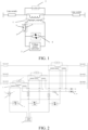
- the series compensator having a fault current limiting function includes a series transformer 1, a series transformer bypass device 2, a voltage source converter 3, a high-speed converter bypass device 4, a high-speed switch 5, and a reactor 6.
- the series transformer 1 is a single-phase transformer; the reactor 6 is connected in parallel to the high-speed switch 5 to form a current limiting module 7; two ends of a first winding of the series transformer 1 are connected in series to a line; a first end of a second winding of the series transformer 1 is connected to a first end of the current limiting module 7; a second end of the current limiting module 7 is connected to a first end of the high-speed converter bypass device 4; a second end of the high-speed converter bypass device 4 is connected to a second end of the second winding of the series transformer 1; a first output end of the voltage source converter 3 is connected to the second end of the current limiting module 7 and the first end of the high-speed converter bypass device 4; a second output end of the voltage source converter 3 is connected to the second end of the second winding of the series transformer; and two ends of the first winding of the series transformer 1 are connected in parallel to one series transformer bypass device 2.
- the series transformer 1 is a three-phase transformer; two ends of three phases of a first winding of the series transformer 1 are connected in series to a three-phase alternating current line, respectively; two ends of the first winding of the series transformer 1 are connected in parallel to one series transformer bypass device 2; the reactor 6 and the high-speed switch 5 are connected in parallel to form a current limiting module 7; a second winding of the series transformer 1 is in a star connection; three phases of an output end of the second winding of the series transformer 1 are connected to three phases of the first end of the current limiting module 7, respectively; three phases of the second end of the current limiting module 7 are connected to three phases of the first end of the high-speed converter bypass device 4, respectively; three phases of the second end of the high-speed converter bypass device 4 are connected to a neutral line of the second winding of the series transformer 1; and a three-phase alternating current output side of the voltage
- the series transformer 1 further includes a third winding; a winding of one phase of the third winding is connected in series to one reactor 20, and then is sequentially connected to windings of the other two phases end-to-end to form a triangle structure and form a three-phase output end; one end of the three-phase output ends is directly grounded, and the other two ends are connected to the overvoltage protection device 19 and then are grounded; and the overvoltage protection device includes a arrester and a gap.
- the neutral line of the second winding of the series transformer 1 is directly grounded, or is electrically grounded by means of a resistor, or is grounded by means of a reactor.
- FIG. 3 shows a third preferred embodiment of the series compensator having a fault current limiting function provided by the present invention.
- the series transformer 1 is a three-phase transformer; two ends of three phases of a first winding of the series transformer 1 are connected in series to a three-phase alternating current line, respectively; two ends of the first winding of the series transformer 1 are connected in parallel to one series transformer bypass device 2; the reactor 6 and the high-speed switch 5 are connected in parallel to form a current limiting module 7; a second winding of the series transformer 1 is in an triangle connection; three-phase windings of the second winding of the series transformer 1 are sequentially connected end-to-end to form a triangle structure and form a three-phase output end; a three-phase output end of the second winding of the series transformer 1 is connected to three phases of the first end of the current limiting module 7, respectively; three phases of the second end of the current limiting module 7 are connected to three phases of an alternating current output end of the voltage source converter 3, respectively; three-phase devices of the
- FIG. 4 shows a fourth preferred embodiment of the series compensator having a fault current limiting function provided by the present invention.
- the current limiting module 7 further includes at least one capacitor 8; the capacitor 8 is connected in parallel to the reactor 6 to form an impedance unit, and the impedance unit is connected in parallel to the high-speed switch 5 to form a current limiting module 7.
- FIG. 5 shows a fifth preferred embodiment of the series compensator having a fault current limiting function provided by the present invention.
- the first winding of the series transformer 1 is connected in parallel to one overvoltage protection device 9, and two ends of the high-speed converter bypass device 4 are connected in parallel to one overvoltage protection device 10; and the overvoltage protection device 9 and the overvoltage protection device 10 include an arrester and a gap.
- the series transformer bypass device 2 is a mechanical bypass switch, or is a bypass switch composed of power electronic devices;
- the high-speed converter bypass device 4 is a high-speed mechanical bypass switch, or a high-speed bypass switch composed of power electronic devices;
- the high-speed switch 5 is a mechanical switch, or a switch composed of power electronic devices.
- one end of the first winding of the series transformer 1 is connected to one end of the series transformer bypass device by means of a breaker, and the other end thereof is connected to the other end of the series transformer bypass device by means of an isolating switch; or two ends of a winding of the series transformer connected to the line are connected to two ends of the series transformer bypass device by means of a breaker, respectively.
- a corresponding control method for the series compensator having a fault current limiting function shown in the foregoing embodiments 1 to 5 includes: when an alternating current system is operating normally, keeping the high-speed switch 5 connected in parallel to the reactor 6 in a closed state, the series transformer bypass device 2 in an OFF state, the high-speed converter bypass device 4 in an OFF state, and the voltage source converter 3 in a deblocked state, and switching on the series compensator for operation in the alternating current system; after determining that a serious fault occurs at a near end of a line to which the compensator is connected, first blocking the voltage source converter 3 and switching on the high-speed converter bypass device 4, and then opening the high-speed switch 5 to limit a line fault current; and after determining that the line fault is cleared, switching on the series transformer bypass device 2, and closing the high-speed switch 5.
- the method for determining that a serious fault occurs at a near end of a line includes: detecting that the value of the current flowing through a line to which the series compensator is connected is greater than a preset current threshold and the duration is greater than a preset time.
- the method for determining that the line fault is cleared includes: detecting that the value of the current flowing through a line to which the series compensator is connected is less than a preset current threshold and the duration is greater than the preset time.
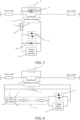
- FIG. 6 shows a sixth preferred embodiment of the series compensator having a fault current limiting function provided by the present invention.
- the series compensator includes a series transformer 1, two series transformer bypass devices 2, a voltage source converter 3, a high-speed converter bypass device 4, N high-speed switches 5, and N reactors 6, where N is a natural number, and N is greater than 1.
- the N reactors 6 are connected in parallel to the N high-speed switches 5, respectively; each reactor 6 is connected in parallel to one high-speed switch 5 to form one current limiting module 7, and a total of N current limiting modules 7 are formed; the N current limiting modules 7 are sequentially connected in series to form one current limiting module group 11.
- Two ends of the first winding of the series transformer 1 are connected in series to a line; a first end of the second winding is connected to a first end of the current limiting module group 11; a second end of the current limiting module group is connected to a first end of the high-speed converter bypass device 4; a second end of the high-speed converter bypass device 4 is connected to a second end of the second winding of the series transformer 1; an output end of the voltage source converter 3 is connected to a second end of the current limiting module group 11 and the first end of the high-speed converter bypass device 4.
- Two ends of two windings of the series transformer 1 are connected in parallel to one series transformer bypass device 2, respectively.
- a control method for the series compensator having a fault current limiting function shown in FIG. 6 includes:
- the first specified rule is to calculate the number of the current limiting modules 7 in the line required by the series compensator according to the requirements for system power flow optimization.
- the second specified rule is to set m preset current thresholds, and if it is detected that the value of the current flowing through a line to which the series compensator is connected is greater than the m-th preset current threshold and the duration is greater than the m-th preset time, then opening the high-speed switches 5 of m current limiting modules 7 in the current limiting module group 11, where m is a natural number, and m is less than or equal to N.
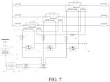
- FIG. 7 shows a preferred embodiment of the unified power flow controller provided by the present invention.
- a series part of the unified power flow controller has the same structure as the series compensator having a fault current limiting function.
- the unified power flow controller includes a series part and a parallel part.
- the series part includes a series transformer 1, a series transformer bypass device 2, a voltage source converter 3, a high-speed converter bypass device 4, a high-speed switch 5, a reactor 6, and a transformer neutral line grounding resistor 18;
- the parallel part includes a voltage source converter 12, a parallel transformer 13, an alternating current breaker 14, a resistor 16, and an isolating switch 17.
- the series transformer 1 is a three-phase transformer; two ends of three phases of a first winding of the series transformer 1 are connected in series to a three-phase alternating current line, respectively; two ends of the first winding of the series transformer 1 are connected in parallel to one series transformer bypass device 2; the reactor 6 and the high-speed switch 5 are connected in parallel to form a current limiting module 7; a second winding of the series transformer 1 is in a star connection; three phases of an output end of the second winding of the series transformer 1 are connected to three phases of the first end of the current limiting module 7, respectively; three phases of the second end of the current limiting module 7 are connected to three phases of the first end of the high-speed converter bypass device 4, respectively; three phases of the second end of the high-speed converter bypass device 4 are connected to a neutral line of the second winding of the series transformer 1; the neutral line of the second winding of the series transformer 1 is grounded by means of the transformer grounding resistor 18; the three-phase alternating current output side of the voltage source converter 3 is connected to
- a direct current output side of the voltage source converter 3 is connected in parallel to a direct current output side of the voltage source converter 12; the resistor 16 and the isolating switch 17 are connected in parallel to form a starting circuit 15; the three-phase alternating current output side of the voltage source converter 12 is connected to three phases of a first end of the starting circuit 15; a second end of the starting circuit 15 is connected to a first end of the parallel transformer 13; a second end of the parallel transformer 13 is connected to a first end of the alternating current breaker 14; a second end of the alternating current breaker 14 is connected to an alternating current bus.
- elements such as reactors, resistors, and switches, in the present invention
- the equivalent elements in the circuit structure may be individual elements or formed by cascading (series, parallel, etc.) multiple same elements.
- the connection among the elements in the embodiments of the present invention is the most basic connection. In practice, connection methods commonly used in power systems and conventional connection devices may be used for connection.
Landscapes
- Engineering & Computer Science (AREA)
- Power Engineering (AREA)
- Physics & Mathematics (AREA)
- Electromagnetism (AREA)
- General Engineering & Computer Science (AREA)
- General Physics & Mathematics (AREA)
- Automation & Control Theory (AREA)
- Inverter Devices (AREA)
- Supply And Distribution Of Alternating Current (AREA)
- Control Of Electrical Variables (AREA)
Claims (15)
- Compensateur série, comprenant :un transformateur série (1), au moins un dispositif de dérivation de transformateur série (2), un convertisseur de source de tension (3), au moins un dispositif de dérivation de convertisseur à haute vitesse (4), au moins un commutateur à haute vitesse (5), et au moins un réacteur (6), dans lequelle réacteur et le commutateur à haute vitesse sont connectés en parallèle pour former un module de limitation de courant (7) ;un enroulement du transformateur série présente deux extrémités pouvant être connectées en série à une ligne, et l'autre enroulement de celui-ci est connecté séquentiellement au module de limitation de courant (7) et au dispositif de dérivation de convertisseur à haute vitesse (4) ; le convertisseur de source de tension (3) et le dispositif de dérivation de convertisseur à haute vitesse (4) sont connectés en parallèle ; et au moins un enroulement du transformateur série (1) est connecté en parallèle à l'au moins un dispositif de dérivation de transformateur série (2).
- Compensateur série selon la revendication 1, dans lequel le transformateur série est un transformateur monophasé ; deux extrémités d'un premier enroulement du transformateur série peuvent être connectées en série à une ligne ; une première extrémité d'un deuxième enroulement du transformateur série est connectée à une première extrémité du module de limitation de courant ; une deuxième extrémité du module de limitation de courant est connectée à une première extrémité du dispositif de dérivation de convertisseur à haute vitesse ; une deuxième extrémité du dispositif de dérivation de convertisseur à haute vitesse est connectée à une deuxième extrémité du deuxième enroulement du transformateur série ; et une première extrémité de sortie du convertisseur de source de tension est connectée à la première extrémité du dispositif de dérivation de convertisseur à haute vitesse, et une deuxième extrémité de sortie du convertisseur de source de tension est connectée à la deuxième extrémité du deuxième enroulement du transformateur série.
- Compensateur série selon la revendication 1, dans lequel le transformateur série est un transformateur triphasé ; deux extrémités de trois phases d'un premier enroulement du transformateur série peuvent être respectivement connectées en série à une ligne de courant alternatif triphasée ;un deuxième enroulement du transformateur série est en connexion étoile ;trois phases d'une extrémité de sortie du deuxième enroulement du transformateur série sont respectivement connectées à trois phases de la première extrémité du module de limitation de courant ; trois phases de la deuxième extrémité du module de limitation de courant sont respectivement connectées à trois phases de la première extrémité du dispositif de dérivation de convertisseur à haute vitesse ;trois phases de la deuxième extrémité du dispositif de dérivation de convertisseur à haute vitesse peuvent être connectées à une ligne neutre du deuxième enroulement du transformateur série ; et un côté sortie de courant alternatif triphasé du convertisseur de source de tension est connecté à trois phases de la deuxième extrémité du module de limitation de courant.
- Compensateur série selon la revendication 1, dans lequel le transformateur série est un transformateur triphasé ; deux extrémités de trois phases d'un premier enroulement du transformateur série peuvent être respectivement connectées en série à une ligne de courant alternatif triphasée ;un deuxième enroulement du transformateur série est en connexion triangulaire ; les enroulements triphasés du deuxième enroulement du transformateur série sont connectés séquentiellement bout à bout pour former une structure triangulaire et former une extrémité de sortie triphasée ;une extrémité de sortie triphasée du deuxième enroulement du transformateur série est respectivement connectée à trois phases de la première extrémité du module de limitation de courant ;trois phases de la deuxième extrémité du module de limitation de courant sont respectivement connectées à trois phases d'une extrémité de sortie de courant alternatif du convertisseur de source de tension ;des dispositifs triphasés du dispositif de dérivation de convertisseur à haute vitesse sont connectés séquentiellement bout à bout pour former une structure triangulaire et former une extrémité de sortie triphasée ; etl'extrémité de sortie triphasée du dispositif de dérivation de convertisseur à haute vitesse est respectivement connectée à trois phases de l'extrémité de sortie de courant alternatif du convertisseur de source de tension.
- Compensateur série selon la revendication 1, dans lequel le module de limitation de courant comprend en outre au moins un condensateur ; le condensateur est connecté en parallèle au réacteur pour former une unité d'impédance ; et l'unité d'impédance est connectée en parallèle au commutateur à haute vitesse pour former un module de limitation de courant.
- Compensateur série selon la revendication 1, dans lequel une extrémité du premier enroulement du transformateur série est connectée à une extrémité du dispositif de dérivation de transformateur série au moyen d'un disjoncteur, et l'autre extrémité de celui-ci est connectée à l'autre extrémité du dispositif de dérivation de transformateur série au moyen d'un commutateur d'isolement ; ou deux extrémités d'un enroulement du transformateur série pouvant être connectées à la ligne sont respectivement connectées à deux extrémités du dispositif de dérivation de transformateur série au moyen d'un disjoncteur.
- Compensateur série selon la revendication 1, dans lequel au moins un enroulement du transformateur série est connecté en parallèle à au moins un dispositif de protection contre les surtensions ; et deux extrémités du dispositif de dérivation de convertisseur à haute vitesse sont connectées en parallèle à au moins un dispositif de protection contre les surtensions.
- Compensateur série selon la revendication 1, dans lequel le dispositif de dérivation de transformateur série est un commutateur de dérivation mécanique, ou est un commutateur de dérivation composé de dispositifs électroniques de puissance ; le dispositif de dérivation de convertisseur à haute vitesse est un commutateur de dérivation mécanique à haute vitesse, ou un commutateur de dérivation à haute vitesse composé de dispositifs électroniques de puissance ; et
le commutateur à haute vitesse est un commutateur mécanique ou un commutateur composé de dispositifs électroniques de puissance. - Compensateur série selon la revendication 3, dans lequel le transformateur série comprend un troisième enroulement ; un enroulement d'une phase du troisième enroulement est connecté en série à un réacteur (20), puis est connecté séquentiellement aux enroulements des deux autres phases bout à bout pour former une structure triangulaire et former une extrémité de sortie triphasée ;
la ligne neutre du deuxième enroulement du transformateur série est directement mise à la terre, ou est mise à la terre électriquement au moyen d'une résistance (18), ou est mise à la terre au moyen d'un réacteur. - Compensateur série selon la revendication 1, dans lequel le transformateur série comprend N commutateurs à haute vitesse et N réacteurs, où N est un nombre naturel et N est supérieur à 1 ; les N réacteurs sont respectivement connectés en parallèle aux N commutateur à haute vitesse ; chaque réacteur est connecté en parallèle à un commutateur à haute vitesse pour former un module de limitation de courant, et un total de N modules de limitation de courant sont formés ; les N modules de limitation de courant sont connectés séquentiellement en série pour former un groupe de modules de limitation de courant.
- Compensateur série selon la revendication 10, comprenant en outre N condensateurs, dans lequel les N réacteurs sont respectivement connectés en parallèle aux N condensateurs ; chaque réacteur est connecté en parallèle à un condensateur pour former une unité d'impédance, et un total de N unités d'impédance sont formées ; les N unités d'impédance sont respectivement connectées en parallèle aux N commutateurs à haute vitesse ; et chaque unité d'impédance est connectée en parallèle à un commutateur à haute vitesse pour former un module de limitation de courant, et un total de N modules de limitation de courant sont formés.
- Régulateur de flux de puissance unifié, comprenant :une partie série et une partie parallèle,dans lequel la partie série du régulateur de flux de puissance unifié est définie par l'une des revendications 1 à 11 ;la partie parallèle du régulateur de flux de puissance unifié comprend un transformateur parallèle (13), un convertisseur de source de tension (12), un circuit de démarrage (15) et un disjoncteur à courant alternatif (14) ;le circuit de démarrage est composé d'une résistance (16) et d'un commutateur d'isolement (117) connectés en parallèle, ou composé d'une résistance et d'un disjoncteur connectés en parallèle ; etla partie parallèle et la partie série du régulateur de flux de puissance unifié sont connectées l'une à l'autre au moyen d'un côté courant continu du convertisseur de source de tension.
- Procédé de commande du compensateur série selon la revendication1 ;
le procédé de commande du compensateur série comprend :lorsqu'un système à courant alternatif fonctionne normalement, maintenir le commutateur à haute vitesse (5) connecté en parallèle au réacteur (6) dans un état fermé, le dispositif de dérivation de transformateur série (2) dans un état d'arrêt, le dispositif de dérivation de convertisseur à haute vitesse dans un état d'arrêt et le convertisseur de source de tension (3) dans un état débloqué, et mettre en marche le compensateur série pour un fonctionnement dans le système à courant alternatif ;après avoir déterminé qu'un défaut grave se produit au niveau d'une extrémité proche d'une ligne, bloquer d'abord le convertisseur de source tension (3) et mettre en marche le dispositif de dérivation de convertisseur à haute vitesse (4), puis ouvrir le commutateur à haute vitesse (5) connecté en parallèle au réacteur (6) pour limiter un courant de défaut de ligne ; etaprès avoir déterminé que le défaut de ligne est éliminé, mettre en marche le dispositif de dérivation de transformateur série (2) et fermer le commutateur à haute vitesse (5) connecté en parallèle au réacteur (6). - Procédé de commande du compensateur série selon la revendication 13, dans lequel la détermination qu'un défaut grave se produit au niveau d'une extrémité proche d'une ligne signifie spécifiquement la détection que la valeur du courant circulant à travers une ligne à laquelle le compensateur série peut être connecté est supérieure à un seuil de courant prédéfini et que la durée est supérieure à un temps prédéfini ; et
la détermination que le défaut de ligne est éliminé signifie spécifiquement la détection que la valeur du courant circulant à travers la ligne à laquelle le compensateur série peut être connecté est inférieure au seuil de courant prédéfini et que la durée est supérieure au temps prédéfini. - Procédé de commande du compensateur série selon la revendication 13, dans lequel le compensateur série est un compensateur série selon la revendication 10 ;le procédé de commande du compensateur série comprend : lorsqu'un système à courant alternatif fonctionne normalement, mettre en marche et à l'arrêt le module de limitation de courant selon une première règle spécifiée ;maintenir le dispositif de dérivation de transformateur série dans un état d'arrêt, le dispositif de dérivation de convertisseur à haute vitesse dans un état d'arrêt et le convertisseur de source de tension dans un état débloqué, et mettre en marche le compensateur série pour un fonctionnement dans le système à courant alternatif ; etla première règle spécifiée consiste à calculer le nombre de modules de limitation de courant dans la ligne requis par le compensateur série selon les exigences d'optimisation du flux de puissance du système ;après avoir déterminé qu'un défaut grave se produit sur une ligne ou une extrémité proche de la ligne, bloquer d'abord le convertisseur de source de tension et mettre en marche le dispositif de dérivation de convertisseur à haute vitesse, puis mettre en marche le module de limitation de courant selon une deuxième règle spécifiée pour limiter le courant de défaut de ligne ; etla deuxième règle spécifiée consiste à définir m seuils de courant prédéfinis, et s'il est détecté que la valeur du courant circulant à travers une ligne à laquelle le compensateur série est connecté est supérieure au m-ième seuil de courant prédéfini et que la durée est supérieure au m-ième temps prédéfini, alors ouvrir les commutateurs à haute vitesse de m modules de limitation de courant dans le groupe de modules de limitation de courant, où m est un nombre naturel et m est inférieur ou égal à N.
Applications Claiming Priority (2)
| Application Number | Priority Date | Filing Date | Title |
|---|---|---|---|
| CN201711381798.9A CN107947173B (zh) | 2017-12-20 | 2017-12-20 | 一种串联补偿器及控制方法 |
| PCT/CN2018/104949 WO2019119886A1 (fr) | 2017-12-20 | 2018-09-11 | Compensateur série et procédé de commande |
Publications (3)
| Publication Number | Publication Date |
|---|---|
| EP3672008A1 EP3672008A1 (fr) | 2020-06-24 |
| EP3672008A4 EP3672008A4 (fr) | 2020-11-04 |
| EP3672008B1 true EP3672008B1 (fr) | 2024-03-20 |
Family
ID=61941357
Family Applications (1)
| Application Number | Title | Priority Date | Filing Date |
|---|---|---|---|
| EP18891849.4A Active EP3672008B1 (fr) | 2017-12-20 | 2018-09-11 | Compensateur série et procédé de commande |
Country Status (6)
| Country | Link |
|---|---|
| US (1) | US11264794B2 (fr) |
| EP (1) | EP3672008B1 (fr) |
| KR (1) | KR102381846B1 (fr) |
| CN (1) | CN107947173B (fr) |
| RU (1) | RU2740012C1 (fr) |
| WO (1) | WO2019119886A1 (fr) |
Families Citing this family (21)
| Publication number | Priority date | Publication date | Assignee | Title |
|---|---|---|---|---|
| CN107947173B (zh) | 2017-12-20 | 2024-02-02 | 南京南瑞继保电气有限公司 | 一种串联补偿器及控制方法 |
| CN108879623B (zh) * | 2018-06-13 | 2020-06-05 | 南京南瑞继保电气有限公司 | 一种多电压等级直流电网系统及控制保护方法 |
| CN110311380B (zh) * | 2019-07-19 | 2023-05-23 | 云南电网有限责任公司电力科学研究院 | 一种有源接地补偿器控制方法 |
| CN110535133A (zh) * | 2019-09-24 | 2019-12-03 | 全球能源互联网研究院有限公司 | 一种柔性多状态开关装置及系统 |
| CN111049147B (zh) * | 2020-01-15 | 2024-06-18 | 南京南瑞继保电气有限公司 | 一种混合补偿型线路间功率转移装置及其控制方法 |
| WO2021239244A1 (fr) * | 2020-05-29 | 2021-12-02 | Siemens Aktiengesellschaft | Système de convertisseur et son procédé de fonctionnement |
| CN111525583B (zh) * | 2020-06-16 | 2025-09-16 | 全球能源互联网研究院有限公司 | 一种调压变压器及潮流控制系统 |
| CN112103965A (zh) * | 2020-07-30 | 2020-12-18 | 国网浙江省电力有限公司绍兴供电公司 | 一种柔性潮流和短路电流混合控制装置及方法 |
| CN111934302A (zh) * | 2020-07-31 | 2020-11-13 | 国网福建省电力有限公司电力科学研究院 | 一种应用于柔性直流输电系统抑制单相故障短路电流的系统及方法 |
| CN112201503B (zh) * | 2020-10-29 | 2024-07-05 | 中国电力工程顾问集团西北电力设计院有限公司 | 一种用于750kV线路加装限流电抗器接线的闭锁逻辑回路 |
| CN112491077B (zh) * | 2020-11-03 | 2022-07-22 | 南京南瑞继保电气有限公司 | 一种分布式串联补偿器的控制方法及装置 |
| CN112769140A (zh) * | 2020-12-28 | 2021-05-07 | 科华恒盛股份有限公司 | 一种交流稳压器及供电设备 |
| CN113013883B (zh) * | 2021-03-09 | 2022-09-27 | 国网浙江省电力有限公司湖州供电公司 | 一种移动式潮流控制兼融冰系统及控制方法 |
| CN115117900B (zh) * | 2021-03-18 | 2026-03-20 | 南京南瑞继保电气有限公司 | 一种分布式补偿器的协调控制方法及系统 |
| CN113206505B (zh) * | 2021-04-19 | 2023-02-28 | 上海舒盈科技股份有限公司 | 一种智能型高压串联补偿装置 |
| CN113224739B (zh) * | 2021-04-19 | 2024-02-09 | 国网江苏省电力有限公司检修分公司 | 一种同步调相机接地线接地时刻的限流装置 |
| CN113315102B (zh) * | 2021-05-28 | 2022-05-06 | 中国南方电网有限责任公司超高压输电公司检修试验中心 | 多端直流输电系统的直流断路器 |
| CN115173395B (zh) * | 2022-06-01 | 2024-05-14 | 广东电网有限责任公司广州供电局 | 一种基于动态阻抗补偿的配电网无缝合环转电装置 |
| US12278484B2 (en) * | 2022-09-19 | 2025-04-15 | Industrial Technology Research Institute | Bypass seamless switching apparatus and method thereof |
| PL443881A1 (pl) * | 2023-02-23 | 2024-08-26 | Sieć Badawcza Łukasiewicz - Instytut Elektrotechniki | Sposób i układ do zabezpieczenia zwarciowego kompensatora zmian napięcia DVR |
| CN117526260A (zh) * | 2023-11-14 | 2024-02-06 | 国家电网有限公司西北分部 | 一种适用于有源电力系统的分布式短路电流自适应抑制方法 |
Family Cites Families (19)
| Publication number | Priority date | Publication date | Assignee | Title |
|---|---|---|---|---|
| SU1686597A1 (ru) * | 1989-11-02 | 1991-10-23 | Ленинградский горный институт им.Г.В.Плеханова | Устройство продольно-поперечного регулировани напр жени |
| RU2056692C1 (ru) * | 1993-10-21 | 1996-03-20 | Климаш Владимир Степанович | Трансформаторно-тиристорный компенсатор реактивной мощности |
| US5734256A (en) * | 1995-05-31 | 1998-03-31 | General Electric Company | Apparatus for protection of power-electronics in series compensating systems |
| JP3239754B2 (ja) * | 1995-06-20 | 2001-12-17 | 株式会社日立製作所 | 限流装置 |
| JP3432640B2 (ja) * | 1995-06-27 | 2003-08-04 | 三菱電機株式会社 | 変換器保護装置 |
| RU2157041C2 (ru) * | 1998-11-25 | 2000-09-27 | Климаш Владимир Степанович | Способ управления компенсатором отклонения напряжения и реактивной мощности |
| EP1168565A1 (fr) * | 2000-06-30 | 2002-01-02 | ABB Industrie AG | Protection d'un circuit de rétablissement dynamique tension |
| RU113884U1 (ru) * | 2011-08-29 | 2012-02-27 | Федеральное государственное унитарное предприятие "Всероссийский Электротехнический институт им. В.И. Ленина" (ФГУП ВЭИ) | Гибридный токоограничитель |
| CN102983577B (zh) * | 2012-07-13 | 2015-09-23 | 中电普瑞科技有限公司 | 一种采用模块化多电平换流器结构的可转换式静止补偿器 |
| KR101673956B1 (ko) * | 2014-06-03 | 2016-11-22 | 숭실대학교산학협력단 | 전력계통을 보호하기 위한 복합형 초전도 한류기 및 이를 포함하는 차단기 시스템 |
| CN104065063A (zh) * | 2014-07-04 | 2014-09-24 | 南京南瑞继保电气有限公司 | 一种适用于多条线路的统一潮流控制器 |
| CN104052073B (zh) * | 2014-07-10 | 2017-02-01 | 南京南瑞继保电气有限公司 | 一种统一潮流控制器的线路功率控制方法及系统 |
| CN105591384B (zh) * | 2014-11-14 | 2018-12-04 | 国家电网公司 | 一种分布式同步串联补偿器 |
| CN205429749U (zh) * | 2016-03-21 | 2016-08-03 | 重庆朗天通讯股份有限公司 | 一种电力配电网的智能串联补偿装置 |
| CN105977972B (zh) * | 2016-06-22 | 2018-01-19 | 全球能源互联网研究院 | 一种串补与换流器结合的静止同步串联补偿装置 |
| CN106711943A (zh) * | 2016-12-26 | 2017-05-24 | 中电普瑞科技有限公司 | 一种分布式串联耦合潮流控制器的保护装置及方法 |
| CN106786562B (zh) * | 2017-02-23 | 2019-11-01 | 全球能源互联网研究院 | 一种静止同步串联补偿器的自励启动系统及方法 |
| CN107947173B (zh) * | 2017-12-20 | 2024-02-02 | 南京南瑞继保电气有限公司 | 一种串联补偿器及控制方法 |
| CN207612063U (zh) * | 2017-12-20 | 2018-07-13 | 南京南瑞继保电气有限公司 | 一种串联补偿器 |
-
2017
- 2017-12-20 CN CN201711381798.9A patent/CN107947173B/zh active Active
-
2018
- 2018-09-11 EP EP18891849.4A patent/EP3672008B1/fr active Active
- 2018-09-11 US US16/649,113 patent/US11264794B2/en active Active
- 2018-09-11 KR KR1020207008288A patent/KR102381846B1/ko active Active
- 2018-09-11 WO PCT/CN2018/104949 patent/WO2019119886A1/fr not_active Ceased
- 2018-09-11 RU RU2020111349A patent/RU2740012C1/ru active
Also Published As
| Publication number | Publication date |
|---|---|
| EP3672008A4 (fr) | 2020-11-04 |
| RU2740012C1 (ru) | 2020-12-30 |
| CN107947173B (zh) | 2024-02-02 |
| KR102381846B1 (ko) | 2022-04-04 |
| KR20200040859A (ko) | 2020-04-20 |
| CN107947173A (zh) | 2018-04-20 |
| WO2019119886A1 (fr) | 2019-06-27 |
| US11264794B2 (en) | 2022-03-01 |
| US20200295561A1 (en) | 2020-09-17 |
| EP3672008A1 (fr) | 2020-06-24 |
Similar Documents
| Publication | Publication Date | Title |
|---|---|---|
| US11264794B2 (en) | Series compensator and control method | |
| Wang et al. | Coordination of MMCs with hybrid DC circuit breakers for HVDC grid protection | |
| EP2856590B1 (fr) | Procédé d'élimination de panne | |
| EP3107172B1 (fr) | Système de protection pour système de transmission d'énergie électrique cc, convertisseur ca/cc, et procédé de coupure de système de transmission d'énergie électrique cc | |
| CN111987706B (zh) | 一种限流型可控避雷器、换流器、输电系统以及控制方法 | |
| EP3036813B1 (fr) | Protection électrique à coté ac dans un système à haute tension continu | |
| KR20180103181A (ko) | 직류 전류 차단장치 및 제어 방법 | |
| CN110492477A (zh) | 一种环网控制器及控制方法 | |
| CN103618330B (zh) | 一种使用隔离开关带电接入多端柔性直流输电系统的方法 | |
| Jakka et al. | Protection design considerations of a 10 kV SiC MOSFET enabled mobile utilities support equipment based solid state transformer (muse-SST) | |
| US10218170B2 (en) | Current-limiting device utilizing a superconductor for a current-limiting operation | |
| EP3338336B1 (fr) | Ensemble électrique | |
| CN207625293U (zh) | 一种串并联混合型补偿器 | |
| KR20150136534A (ko) | 한류·조류 제어 장치 | |
| CN110535141A (zh) | 一种限流型环网控制器及控制方法 | |
| US20120287544A1 (en) | Isolation-type ac fault current limited circuit | |
| KR101905631B1 (ko) | 한류기 유지 보수 시스템 및 방법 | |
| CN108092250B (zh) | 一种故障限流设备及控制方法 | |
| CN107204609B (zh) | 一种接地方式自识别的配电网母线保护装置及方法 | |
| CN112186720B (zh) | 一种高速短路限流装置 | |
| CN210780094U (zh) | 一种环网控制器 | |
| Jia et al. | An economical hybrid DC circuit breaker with pre-current-limiting capability | |
| CN109038595B (zh) | 一种低容/低抗柔性投切系统及其控制方法 | |
| CN207612063U (zh) | 一种串联补偿器 | |
| CN112968432B (zh) | 一种负压耦合式高压直流断路器的控保系统 |
Legal Events
| Date | Code | Title | Description |
|---|---|---|---|
| STAA | Information on the status of an ep patent application or granted ep patent |
Free format text: STATUS: THE INTERNATIONAL PUBLICATION HAS BEEN MADE |
|
| PUAI | Public reference made under article 153(3) epc to a published international application that has entered the european phase |
Free format text: ORIGINAL CODE: 0009012 |
|
| STAA | Information on the status of an ep patent application or granted ep patent |
Free format text: STATUS: REQUEST FOR EXAMINATION WAS MADE |
|
| 17P | Request for examination filed |
Effective date: 20200320 |
|
| AK | Designated contracting states |
Kind code of ref document: A1 Designated state(s): AL AT BE BG CH CY CZ DE DK EE ES FI FR GB GR HR HU IE IS IT LI LT LU LV MC MK MT NL NO PL PT RO RS SE SI SK SM TR |
|
| AX | Request for extension of the european patent |
Extension state: BA ME |
|
| A4 | Supplementary search report drawn up and despatched |
Effective date: 20201002 |
|
| RIC1 | Information provided on ipc code assigned before grant |
Ipc: H02J 3/18 20060101ALI20200928BHEP Ipc: H02H 9/02 20060101AFI20200928BHEP Ipc: H02J 3/06 20060101ALI20200928BHEP |
|
| DAV | Request for validation of the european patent (deleted) | ||
| DAX | Request for extension of the european patent (deleted) | ||
| GRAP | Despatch of communication of intention to grant a patent |
Free format text: ORIGINAL CODE: EPIDOSNIGR1 |
|
| STAA | Information on the status of an ep patent application or granted ep patent |
Free format text: STATUS: GRANT OF PATENT IS INTENDED |
|
| RIC1 | Information provided on ipc code assigned before grant |
Ipc: H02J 3/18 20060101ALI20230829BHEP Ipc: H02H 9/02 20060101AFI20230829BHEP |
|
| INTG | Intention to grant announced |
Effective date: 20231002 |
|
| GRAS | Grant fee paid |
Free format text: ORIGINAL CODE: EPIDOSNIGR3 |
|
| GRAA | (expected) grant |
Free format text: ORIGINAL CODE: 0009210 |
|
| STAA | Information on the status of an ep patent application or granted ep patent |
Free format text: STATUS: THE PATENT HAS BEEN GRANTED |
|
| AK | Designated contracting states |
Kind code of ref document: B1 Designated state(s): AL AT BE BG CH CY CZ DE DK EE ES FI FR GB GR HR HU IE IS IT LI LT LU LV MC MK MT NL NO PL PT RO RS SE SI SK SM TR |
|
| REG | Reference to a national code |
Ref country code: GB Ref legal event code: FG4D |
|
| REG | Reference to a national code |
Ref country code: CH Ref legal event code: EP |
|
| REG | Reference to a national code |
Ref country code: DE Ref legal event code: R096 Ref document number: 602018067013 Country of ref document: DE |
|
| REG | Reference to a national code |
Ref country code: IE Ref legal event code: FG4D |
|
| REG | Reference to a national code |
Ref country code: GR Ref legal event code: EP Ref document number: 20240400916 Country of ref document: GR Effective date: 20240516 |
|
| PG25 | Lapsed in a contracting state [announced via postgrant information from national office to epo] |
Ref country code: LT Free format text: LAPSE BECAUSE OF FAILURE TO SUBMIT A TRANSLATION OF THE DESCRIPTION OR TO PAY THE FEE WITHIN THE PRESCRIBED TIME-LIMIT Effective date: 20240320 |
|
| REG | Reference to a national code |
Ref country code: LT Ref legal event code: MG9D |
|
| PG25 | Lapsed in a contracting state [announced via postgrant information from national office to epo] |
Ref country code: RS Free format text: LAPSE BECAUSE OF FAILURE TO SUBMIT A TRANSLATION OF THE DESCRIPTION OR TO PAY THE FEE WITHIN THE PRESCRIBED TIME-LIMIT Effective date: 20240620 Ref country code: HR Free format text: LAPSE BECAUSE OF FAILURE TO SUBMIT A TRANSLATION OF THE DESCRIPTION OR TO PAY THE FEE WITHIN THE PRESCRIBED TIME-LIMIT Effective date: 20240320 |
|
| REG | Reference to a national code |
Ref country code: NL Ref legal event code: MP Effective date: 20240320 |
|
| PG25 | Lapsed in a contracting state [announced via postgrant information from national office to epo] |
Ref country code: RS Free format text: LAPSE BECAUSE OF FAILURE TO SUBMIT A TRANSLATION OF THE DESCRIPTION OR TO PAY THE FEE WITHIN THE PRESCRIBED TIME-LIMIT Effective date: 20240620 Ref country code: NO Free format text: LAPSE BECAUSE OF FAILURE TO SUBMIT A TRANSLATION OF THE DESCRIPTION OR TO PAY THE FEE WITHIN THE PRESCRIBED TIME-LIMIT Effective date: 20240620 Ref country code: LT Free format text: LAPSE BECAUSE OF FAILURE TO SUBMIT A TRANSLATION OF THE DESCRIPTION OR TO PAY THE FEE WITHIN THE PRESCRIBED TIME-LIMIT Effective date: 20240320 Ref country code: HR Free format text: LAPSE BECAUSE OF FAILURE TO SUBMIT A TRANSLATION OF THE DESCRIPTION OR TO PAY THE FEE WITHIN THE PRESCRIBED TIME-LIMIT Effective date: 20240320 Ref country code: FI Free format text: LAPSE BECAUSE OF FAILURE TO SUBMIT A TRANSLATION OF THE DESCRIPTION OR TO PAY THE FEE WITHIN THE PRESCRIBED TIME-LIMIT Effective date: 20240320 Ref country code: BG Free format text: LAPSE BECAUSE OF FAILURE TO SUBMIT A TRANSLATION OF THE DESCRIPTION OR TO PAY THE FEE WITHIN THE PRESCRIBED TIME-LIMIT Effective date: 20240320 |
|
| REG | Reference to a national code |
Ref country code: AT Ref legal event code: MK05 Ref document number: 1668689 Country of ref document: AT Kind code of ref document: T Effective date: 20240320 |
|
| PG25 | Lapsed in a contracting state [announced via postgrant information from national office to epo] |
Ref country code: SE Free format text: LAPSE BECAUSE OF FAILURE TO SUBMIT A TRANSLATION OF THE DESCRIPTION OR TO PAY THE FEE WITHIN THE PRESCRIBED TIME-LIMIT Effective date: 20240320 Ref country code: LV Free format text: LAPSE BECAUSE OF FAILURE TO SUBMIT A TRANSLATION OF THE DESCRIPTION OR TO PAY THE FEE WITHIN THE PRESCRIBED TIME-LIMIT Effective date: 20240320 |
|
| PG25 | Lapsed in a contracting state [announced via postgrant information from national office to epo] |
Ref country code: NL Free format text: LAPSE BECAUSE OF FAILURE TO SUBMIT A TRANSLATION OF THE DESCRIPTION OR TO PAY THE FEE WITHIN THE PRESCRIBED TIME-LIMIT Effective date: 20240320 |
|
| PG25 | Lapsed in a contracting state [announced via postgrant information from national office to epo] |
Ref country code: NL Free format text: LAPSE BECAUSE OF FAILURE TO SUBMIT A TRANSLATION OF THE DESCRIPTION OR TO PAY THE FEE WITHIN THE PRESCRIBED TIME-LIMIT Effective date: 20240320 |
|
| PG25 | Lapsed in a contracting state [announced via postgrant information from national office to epo] |
Ref country code: IS Free format text: LAPSE BECAUSE OF FAILURE TO SUBMIT A TRANSLATION OF THE DESCRIPTION OR TO PAY THE FEE WITHIN THE PRESCRIBED TIME-LIMIT Effective date: 20240720 |
|
| PG25 | Lapsed in a contracting state [announced via postgrant information from national office to epo] |
Ref country code: PT Free format text: LAPSE BECAUSE OF FAILURE TO SUBMIT A TRANSLATION OF THE DESCRIPTION OR TO PAY THE FEE WITHIN THE PRESCRIBED TIME-LIMIT Effective date: 20240722 Ref country code: SM Free format text: LAPSE BECAUSE OF FAILURE TO SUBMIT A TRANSLATION OF THE DESCRIPTION OR TO PAY THE FEE WITHIN THE PRESCRIBED TIME-LIMIT Effective date: 20240320 |
|
| PG25 | Lapsed in a contracting state [announced via postgrant information from national office to epo] |
Ref country code: ES Free format text: LAPSE BECAUSE OF FAILURE TO SUBMIT A TRANSLATION OF THE DESCRIPTION OR TO PAY THE FEE WITHIN THE PRESCRIBED TIME-LIMIT Effective date: 20240320 |
|
| PG25 | Lapsed in a contracting state [announced via postgrant information from national office to epo] |
Ref country code: EE Free format text: LAPSE BECAUSE OF FAILURE TO SUBMIT A TRANSLATION OF THE DESCRIPTION OR TO PAY THE FEE WITHIN THE PRESCRIBED TIME-LIMIT Effective date: 20240320 Ref country code: CZ Free format text: LAPSE BECAUSE OF FAILURE TO SUBMIT A TRANSLATION OF THE DESCRIPTION OR TO PAY THE FEE WITHIN THE PRESCRIBED TIME-LIMIT Effective date: 20240320 |
|
| PG25 | Lapsed in a contracting state [announced via postgrant information from national office to epo] |
Ref country code: AT Free format text: LAPSE BECAUSE OF FAILURE TO SUBMIT A TRANSLATION OF THE DESCRIPTION OR TO PAY THE FEE WITHIN THE PRESCRIBED TIME-LIMIT Effective date: 20240320 |
|
| PG25 | Lapsed in a contracting state [announced via postgrant information from national office to epo] |
Ref country code: PL Free format text: LAPSE BECAUSE OF FAILURE TO SUBMIT A TRANSLATION OF THE DESCRIPTION OR TO PAY THE FEE WITHIN THE PRESCRIBED TIME-LIMIT Effective date: 20240320 |
|
| PG25 | Lapsed in a contracting state [announced via postgrant information from national office to epo] |
Ref country code: SK Free format text: LAPSE BECAUSE OF FAILURE TO SUBMIT A TRANSLATION OF THE DESCRIPTION OR TO PAY THE FEE WITHIN THE PRESCRIBED TIME-LIMIT Effective date: 20240320 |
|
| PG25 | Lapsed in a contracting state [announced via postgrant information from national office to epo] |
Ref country code: SM Free format text: LAPSE BECAUSE OF FAILURE TO SUBMIT A TRANSLATION OF THE DESCRIPTION OR TO PAY THE FEE WITHIN THE PRESCRIBED TIME-LIMIT Effective date: 20240320 Ref country code: SK Free format text: LAPSE BECAUSE OF FAILURE TO SUBMIT A TRANSLATION OF THE DESCRIPTION OR TO PAY THE FEE WITHIN THE PRESCRIBED TIME-LIMIT Effective date: 20240320 Ref country code: RO Free format text: LAPSE BECAUSE OF FAILURE TO SUBMIT A TRANSLATION OF THE DESCRIPTION OR TO PAY THE FEE WITHIN THE PRESCRIBED TIME-LIMIT Effective date: 20240320 Ref country code: PT Free format text: LAPSE BECAUSE OF FAILURE TO SUBMIT A TRANSLATION OF THE DESCRIPTION OR TO PAY THE FEE WITHIN THE PRESCRIBED TIME-LIMIT Effective date: 20240722 Ref country code: PL Free format text: LAPSE BECAUSE OF FAILURE TO SUBMIT A TRANSLATION OF THE DESCRIPTION OR TO PAY THE FEE WITHIN THE PRESCRIBED TIME-LIMIT Effective date: 20240320 Ref country code: IS Free format text: LAPSE BECAUSE OF FAILURE TO SUBMIT A TRANSLATION OF THE DESCRIPTION OR TO PAY THE FEE WITHIN THE PRESCRIBED TIME-LIMIT Effective date: 20240720 Ref country code: ES Free format text: LAPSE BECAUSE OF FAILURE TO SUBMIT A TRANSLATION OF THE DESCRIPTION OR TO PAY THE FEE WITHIN THE PRESCRIBED TIME-LIMIT Effective date: 20240320 Ref country code: EE Free format text: LAPSE BECAUSE OF FAILURE TO SUBMIT A TRANSLATION OF THE DESCRIPTION OR TO PAY THE FEE WITHIN THE PRESCRIBED TIME-LIMIT Effective date: 20240320 Ref country code: CZ Free format text: LAPSE BECAUSE OF FAILURE TO SUBMIT A TRANSLATION OF THE DESCRIPTION OR TO PAY THE FEE WITHIN THE PRESCRIBED TIME-LIMIT Effective date: 20240320 Ref country code: AT Free format text: LAPSE BECAUSE OF FAILURE TO SUBMIT A TRANSLATION OF THE DESCRIPTION OR TO PAY THE FEE WITHIN THE PRESCRIBED TIME-LIMIT Effective date: 20240320 |
|
| PG25 | Lapsed in a contracting state [announced via postgrant information from national office to epo] |
Ref country code: IT Free format text: LAPSE BECAUSE OF FAILURE TO SUBMIT A TRANSLATION OF THE DESCRIPTION OR TO PAY THE FEE WITHIN THE PRESCRIBED TIME-LIMIT Effective date: 20240320 |
|
| REG | Reference to a national code |
Ref country code: DE Ref legal event code: R097 Ref document number: 602018067013 Country of ref document: DE |
|
| PG25 | Lapsed in a contracting state [announced via postgrant information from national office to epo] |
Ref country code: IT Free format text: LAPSE BECAUSE OF FAILURE TO SUBMIT A TRANSLATION OF THE DESCRIPTION OR TO PAY THE FEE WITHIN THE PRESCRIBED TIME-LIMIT Effective date: 20240320 |
|
| PG25 | Lapsed in a contracting state [announced via postgrant information from national office to epo] |
Ref country code: DK Free format text: LAPSE BECAUSE OF FAILURE TO SUBMIT A TRANSLATION OF THE DESCRIPTION OR TO PAY THE FEE WITHIN THE PRESCRIBED TIME-LIMIT Effective date: 20240320 |
|
| PLBE | No opposition filed within time limit |
Free format text: ORIGINAL CODE: 0009261 |
|
| STAA | Information on the status of an ep patent application or granted ep patent |
Free format text: STATUS: NO OPPOSITION FILED WITHIN TIME LIMIT |
|
| PG25 | Lapsed in a contracting state [announced via postgrant information from national office to epo] |
Ref country code: DK Free format text: LAPSE BECAUSE OF FAILURE TO SUBMIT A TRANSLATION OF THE DESCRIPTION OR TO PAY THE FEE WITHIN THE PRESCRIBED TIME-LIMIT Effective date: 20240320 |
|
| 26N | No opposition filed |
Effective date: 20241223 |
|
| PG25 | Lapsed in a contracting state [announced via postgrant information from national office to epo] |
Ref country code: MC Free format text: LAPSE BECAUSE OF FAILURE TO SUBMIT A TRANSLATION OF THE DESCRIPTION OR TO PAY THE FEE WITHIN THE PRESCRIBED TIME-LIMIT Effective date: 20240320 Ref country code: SI Free format text: LAPSE BECAUSE OF FAILURE TO SUBMIT A TRANSLATION OF THE DESCRIPTION OR TO PAY THE FEE WITHIN THE PRESCRIBED TIME-LIMIT Effective date: 20240320 |
|
| REG | Reference to a national code |
Ref country code: CH Ref legal event code: PL |
|
| PG25 | Lapsed in a contracting state [announced via postgrant information from national office to epo] |
Ref country code: LU Free format text: LAPSE BECAUSE OF NON-PAYMENT OF DUE FEES Effective date: 20240911 |
|
| REG | Reference to a national code |
Ref country code: BE Ref legal event code: MM Effective date: 20240930 |
|
| PG25 | Lapsed in a contracting state [announced via postgrant information from national office to epo] |
Ref country code: BE Free format text: LAPSE BECAUSE OF NON-PAYMENT OF DUE FEES Effective date: 20240930 |
|
| PG25 | Lapsed in a contracting state [announced via postgrant information from national office to epo] |
Ref country code: CH Free format text: LAPSE BECAUSE OF NON-PAYMENT OF DUE FEES Effective date: 20240930 |
|
| PGFP | Annual fee paid to national office [announced via postgrant information from national office to epo] |
Ref country code: DE Payment date: 20250923 Year of fee payment: 8 |
|
| PGFP | Annual fee paid to national office [announced via postgrant information from national office to epo] |
Ref country code: GR Payment date: 20250925 Year of fee payment: 8 |
|
| PGFP | Annual fee paid to national office [announced via postgrant information from national office to epo] |
Ref country code: GB Payment date: 20250927 Year of fee payment: 8 |
|
| PGFP | Annual fee paid to national office [announced via postgrant information from national office to epo] |
Ref country code: FR Payment date: 20250926 Year of fee payment: 8 |
|
| PGFP | Annual fee paid to national office [announced via postgrant information from national office to epo] |
Ref country code: IE Payment date: 20250926 Year of fee payment: 8 |
|
| PG25 | Lapsed in a contracting state [announced via postgrant information from national office to epo] |
Ref country code: CY Free format text: LAPSE BECAUSE OF FAILURE TO SUBMIT A TRANSLATION OF THE DESCRIPTION OR TO PAY THE FEE WITHIN THE PRESCRIBED TIME-LIMIT; INVALID AB INITIO Effective date: 20180911 |
|
| PG25 | Lapsed in a contracting state [announced via postgrant information from national office to epo] |
Ref country code: HU Free format text: LAPSE BECAUSE OF FAILURE TO SUBMIT A TRANSLATION OF THE DESCRIPTION OR TO PAY THE FEE WITHIN THE PRESCRIBED TIME-LIMIT; INVALID AB INITIO Effective date: 20180911 |
|
| PG25 | Lapsed in a contracting state [announced via postgrant information from national office to epo] |
Ref country code: TR Free format text: LAPSE BECAUSE OF FAILURE TO SUBMIT A TRANSLATION OF THE DESCRIPTION OR TO PAY THE FEE WITHIN THE PRESCRIBED TIME-LIMIT Effective date: 20240320 |