EP3672034B1 - Structure de refroidissement de stator de machine électrique rotative - Google Patents
Structure de refroidissement de stator de machine électrique rotative Download PDFInfo
- Publication number
- EP3672034B1 EP3672034B1 EP18848460.4A EP18848460A EP3672034B1 EP 3672034 B1 EP3672034 B1 EP 3672034B1 EP 18848460 A EP18848460 A EP 18848460A EP 3672034 B1 EP3672034 B1 EP 3672034B1
- Authority
- EP
- European Patent Office
- Prior art keywords
- refrigerant
- stator
- electrical machine
- rotating electrical
- cooling structure
- Prior art date
- Legal status (The legal status is an assumption and is not a legal conclusion. Google has not performed a legal analysis and makes no representation as to the accuracy of the status listed.)
- Active
Links
Images

Classifications
-
- H—ELECTRICITY
- H02—GENERATION; CONVERSION OR DISTRIBUTION OF ELECTRIC POWER
- H02K—DYNAMO-ELECTRIC MACHINES
- H02K3/00—Details of windings
- H02K3/04—Windings characterised by the conductor shape, form or construction, e.g. with bar conductors
- H02K3/24—Windings characterised by the conductor shape, form or construction, e.g. with bar conductors with channels or ducts for cooling medium between the conductors
-
- H—ELECTRICITY
- H02—GENERATION; CONVERSION OR DISTRIBUTION OF ELECTRIC POWER
- H02K—DYNAMO-ELECTRIC MACHINES
- H02K1/00—Details of the magnetic circuit
- H02K1/06—Details of the magnetic circuit characterised by the shape, form or construction
- H02K1/12—Stationary parts of the magnetic circuit
- H02K1/20—Stationary parts of the magnetic circuit with channels or ducts for flow of cooling medium
-
- H—ELECTRICITY
- H02—GENERATION; CONVERSION OR DISTRIBUTION OF ELECTRIC POWER
- H02K—DYNAMO-ELECTRIC MACHINES
- H02K9/00—Arrangements for cooling or ventilating
- H02K9/19—Arrangements for cooling or ventilating for machines with closed casing and closed-circuit cooling using a liquid cooling medium, e.g. oil
-
- H—ELECTRICITY
- H02—GENERATION; CONVERSION OR DISTRIBUTION OF ELECTRIC POWER
- H02K—DYNAMO-ELECTRIC MACHINES
- H02K5/00—Casings; Enclosures; Supports
- H02K5/04—Casings or enclosures characterised by the shape, form or construction thereof
- H02K5/16—Means for supporting bearings, e.g. insulating supports or means for fitting bearings in the bearing-shields
- H02K5/173—Means for supporting bearings, e.g. insulating supports or means for fitting bearings in the bearing-shields using bearings with rolling contact, e.g. ball bearings
- H02K5/1732—Means for supporting bearings, e.g. insulating supports or means for fitting bearings in the bearing-shields using bearings with rolling contact, e.g. ball bearings radially supporting the rotary shaft at both ends of the rotor
Definitions
- the present invention relates to a cooling structure of a stator of a rotating electrical machine.
- Patent Publication 1 discloses a cooling device of a vehicle power transmission apparatus in which an outer peripheral annular oil tube and an inner peripheral annular oil tube are provided, these are respectively formed with a plurality of discharging holes for discharging cooling oil toward coil ends, and cooling oil is supplied to the annular oil tubes, thereby uniformly supplying cooling oil in the circumferential direction of the coil ends.
- Patent Publication 2 discloses an oil cooling structure of a motor, in which an oil passage cover that covers an opening surface of a circumferential oil passage extending along the circumferential direction of a motor is formed with a plurality of discharging holes at predetermined intervals, and oil is supplied from these discharging holes towards the clearances between adjacent coils, thereby supplying oil to all of the coils.
- each of the following Patent Publications 3 and 4 discloses a cooling structure of a rotating electrical machine, in which a side cover for protecting a rotor and a stator is formed with a discharging hole for supplying refrigerant via a passage, and refrigerant is discharged from this discharging hole, thereby improving coil cooling efficiency.
- Patent Publication 5 discloses a cooling structure of a rotating electrical machine, in which there is provided a refrigerant passage tube that extends in the circumferential direction along an outer end surface in the axial direction of the rotating electrical machine, and a plurality of openings that communicate with the inside of the tube are formed at positions that are opposed to the outer end surface in the axial direction of the rotating electrical machine and are on an outer peripheral surface of this refrigerant passage tube, thereby efficiently cooling the rotating electrical machine.
- a cooling structure according to the preamble of claim 1 is known from Patent Publication 7.
- a cooling structure of a stator of a rotating electrical machine is capable of surely cooling a stator coil end of each unit coil of a rotating electrical machine, and simultaneously cooling and lubricating a bearing that supports a rotation shaft of said rotating electrical machine.
- the rotating electrical machine is equipped with a rotation shaft 3 that is rotatably supported in a casing 1 through bearings 2, a rotor (not shown in the drawings) that is fixed to an outer peripheral portion of the rotation shaft 3, and a stator 4 that is disposed to be opposed to the outer peripheral portion of the rotor through an air gap and is fixed to the casing 1.
- the casing 1 is constituted to include a generally cylindrical frame 11, and a non-direct-coupling-side bracket 12 and a direct-coupling-side bracket 13 that are mounted on opening portions of this frame 11.
- stator 4 is equipped with stator cores 41 and stator coils wound around the stator cores 41.
- stator coil ends 42A, 42B parts that project from the stator core 41 of this stator coil 42 toward axial both sides (non-direct-coupling side and direct-coupling side) are referred to as stator coil ends 42A, 42B.
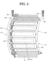
- the stator coil 42 is formed by concentrated winding. An end portion (exit wire) of a wire that forms each unit coil 42a (see Fig. 5 ) is disposed on the non-direct-coupling side. The exit wire is connected by a bus bar 43 per each phase.
- this rotating electrical machine is equipped with a refrigerant supplying body for supplying a refrigerant (cooling oil) to stator coil ends 42A, 42B, etc.
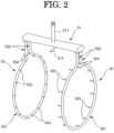
- the refrigerant supplying body is constituted to include a refrigerant introducing portion 51 that extends along the axial direction, and oil guides 52, 53 that are connected to both sides in the axial direction of the refrigerant introducing portion 51.
- the refrigerant introducing portion 51 is a hollow cylindrical body and is fixed, for example, to the frame 11.
- the refrigerant introducing portion 51 is formed into an oval shape in sectional view.
- This refrigerant introducing portion 51 has an inflow portion 511 for introducing refrigerant that is supplied from the outside of the casing 1, refrigerant supply ports 512, 513 that are respectively connected to the oil guides 52, 53, and a refrigerant supplying nozzle 514 for supplying refrigerant onto the stator cores 41.
- the oil guides 52, 53 are made of an insulator (e.g., resin) having heat resistance and oil resistance and are respectively fixed, for example, to brackets 12, 13.
- the oil guides 52, 53 are those each prepared by forming a tube with opened both ends into a generally arc shape, and the both ends extend generally straight toward the outside in the radial direction.
- arc parts of the oil guides 52, 53 are referred to as arc portions 521, 531, and straight parts toward the outside in the radial direction are referred to as straight portions 522, 532.
- the arc portions 521, 531 and the straight portions 522, 532 constitute a refrigerant passage.
- the arc portions 521, 531 of these oil guides 52, 53 are respectively disposed to be opposed to axial end portions of the stator coil ends 42A, 42B. Furthermore, tip ends (opening portions) of the straight portions 522, 532 of the oil guides 52, 53 are respectively connected to the refrigerant supply ports 512, 513 of the refrigerant introducing portion 51.
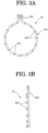
- the oil guide 52 is provided with a refrigerant discharging portion 523 of the arc portion 521 that is formed at a position corresponding to the stator coil end 42A of each unit coil 42a, and refrigerant discharging portions (other refrigerant discharging portions) 524 of the straight portions 522 that are formed at positions opposed to an inner peripheral surface of the casing 1.
- the refrigerant discharging portion 523 of the oil guide 52 is a projection portion that extends from the arc portion 521 toward the stator coil end 42A side. That is, the refrigerant discharging portion 523 is constituted to eject refrigerant from a tip end of a projection that extends from the arc portion 521 toward the stator coil end 42A. As shown in Fig. 5 , the refrigerant discharging portion 523 is arranged such that its tip end is positioned on the stator coil end 42A side than the tip end of the exit wire and the tip end of the bus bar 43.
- the refrigerant discharging portion 524 of the oil guide 52 is a projection portion that extends from the straight portion 522 toward the inner peripheral surface side of the casing 1. That is, the refrigerant discharging portion 524 is constituted to eject refrigerant from a tip end of a projection that extends from the straight portion 522 toward the inner peripheral surface of the casing 1.
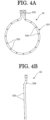
- the oil guide 53 is provided with a refrigerant discharging portion 523 of the arc portion 531 that is formed at a position corresponding to the stator coil end 42B of each unit coil 42a, and refrigerant discharging portions (other refrigerant discharging portions) 534 of the straight portions 532 that are formed at positions opposed to an inner peripheral surface of the casing 1.
- a refrigerant discharging portion 533 of the oil guide 53 is an opened hole that is formed in the arc portion 531 and is constituted to directly eject refrigerant from the arc portion 531 toward the stator coil end 42B.
- the refrigerant discharging portion 534 of the oil guide 53 is formed to project from the straight portion 532 toward inner peripheral surface side of the casing 1. That is, the refrigerant discharging portion 534 is constituted to eject refrigerant from a tip end of a projection that extends from the straight portion 532 towards the inner peripheral surface of the casing 1.
- stator cooling structure of a rotating electrical machine configured as above, it is possible to surely supply refrigerant from the refrigerant discharging portion 523, 533 of the oil guide 52, 53 to the stator coil end 42A, 42B of each unit coil 42a. Therefore, it is possible to uniformly cool the stator coil ends 42A, 42B in the circumferential direction.
- the refrigerant discharging portion 523 is formed into a projection portion that extends towards the stator coil end 42A. With this, the refrigerant can reach the stator coil end 42A of each unit coil 42a. Therefore, it becomes possible to surely cool the stator coil end 42A.
- the refrigerant discharging portion 524, 534 is formed at a position of the straight portion 522, 532 of the oil guide 52, 53 that corresponds to the inner peripheral surface of the casing 1 to supply refrigerant toward the inner peripheral surface of the casing 1. With this, it also becomes possible to conduct cooling and lubrication of the bearing 2.
- the oil guide 52 is formed by an insulator, it is possible to extend the refrigerant discharging portion 523 of the oil guide 52 to the vicinity of the stator coil end 42A. With this, it becomes possible to surely supply refrigerant to the stator coil end 42A.
- the refrigerant discharging portion 533 of the oil guide 53 that is disposed to be opposed to the direct-coupling-side stator coil end 42B is an opened hole formed in the arc portion 531.
- the refrigerant discharging portion 533 may be formed to project from the arc portion 531 toward the side of the stator coil end 42B.
- each of the oil guides 52, 53 is formed in one piece.
- the arc portion 521, 531 may be separated into those in a semicircular shape by a lower portion.
- the refrigerant introducing portion 51 is installed on the inner side of the casing 1.
- the refrigerant introducing portion 51 may be embedded in the inside of the frame 11 or may be directly formed in the frame 11.
- refrigerant discharging portion 523, 533 is provided relative to the stator coil end 42A, 42B of each unit coil 42a.
- a plurality of refrigerant discharging portions may be provided relative to the stator coil end 42A, 42B of each unit coil 42a.
Landscapes
- Engineering & Computer Science (AREA)
- Power Engineering (AREA)
- Motor Or Generator Cooling System (AREA)
- Iron Core Of Rotating Electric Machines (AREA)
Claims (4)
- Structure de refroidissement pour un stator (4) d'une machine électrique rotative pour alimenter un réfrigérant à des extrémités de bobine de stator (42A), la structure de refroidissement étant équipée d'un guide d'huile (52) qui est agencé dans un boîtier (1) de la machine électrique rotative, le guide d'huile (52) comprenant :un tube en forme d'arc (521) formant un premier passage à réfrigérant à l'intérieur de celui-ci, le tube en forme d'arc (521) étant agencé dans un plan perpendiculaire à l'axe de stator et étant opposé à une portion d'extrémité axiale d'une extrémité de bobine de stator (42A), le tube en forme d'arc (521) étant configuré de telle sorte que, en fonctionnement, le réfrigérant est introduit jusque dans le premier passage à réfrigérant ; etune première portion de décharge de réfrigérant (523) qui se projette dans une première direction axiale depuis une surface du tube en forme d'arc (521) vers l'extrémité de bobine de stator (42A) de chaque bobine unitaire (42a), la première portion de décharge de réfrigérant (523) formant à l'intérieur de celle-ci un second passage à réfrigérant en communication avec le premier passage à réfrigérant de telle sorte que le réfrigérant, en fonctionnement, passe depuis le premier passage à réfrigérant jusqu'au second passage à réfrigérant, et puis est déchargé depuis une extrémité de pointe de la première portion de décharge de réfrigérant (523) vers l'extrémité de bobine stator (42A) de chaque bobine unitaire (42a),caractérisée en ce que le guide d'huile (52) comprend en outre une seconde portion de décharge de réfrigérant (524) positionnée en fonctionnement au-dessus d'un palier (2) qui supporte un arbre rotatif (3) de la machine électrique rotative, le palier (2) étant prévu sur une surface périphérique intérieure du boîtier (1), la seconde portion de décharge de réfrigérant (524) se projetant dans une seconde direction axiale, qui est opposée à la première direction axiale, depuis une surface du tube en forme d'arc (521) et étant configurée pour décharger le réfrigérant depuis une extrémité de pointe de la seconde portion de décharge de réfrigérant (524) vers la surface périphérique intérieure du boîtier (1) pour alimenter le réfrigérant pour le refroidissement et la lubrification du palier (2).
- Structure de refroidissement pour le stator (4) de la machine électrique rotative selon la revendication 1, qui est caractérisée en ce que le guide d'huile (52) comprend un isolant ayant une résistance à la chaleur et une résistance à l'huile.
- Structure de refroidissement pour le stator de la machine électrique rotative selon la revendication 1 ou 2, qui est caractérisée en ce que chaque bobine unitaire (42a) est formée par enroulement concentré.
- Structure de refroidissement pour le stator de la machine électrique rotative selon l'une quelconque des revendications 1 à 3, qui est caractérisée en ce que le guide d'huile (52) est disposé pour être opposé à l'extrémité de bobine de stator (42A) sur un côté sur lequel une portion d'extrémité d'un fil constituant une bobine est positionnée.
Applications Claiming Priority (2)
| Application Number | Priority Date | Filing Date | Title |
|---|---|---|---|
| JP2017161829A JP6436200B1 (ja) | 2017-08-25 | 2017-08-25 | 回転電機の固定子の冷却構造 |
| PCT/JP2018/029323 WO2019039243A1 (fr) | 2017-08-25 | 2018-08-06 | Structure de refroidissement de stator de machine électrique rotative |
Publications (3)
| Publication Number | Publication Date |
|---|---|
| EP3672034A1 EP3672034A1 (fr) | 2020-06-24 |
| EP3672034A4 EP3672034A4 (fr) | 2021-04-28 |
| EP3672034B1 true EP3672034B1 (fr) | 2024-10-23 |
Family
ID=64655831
Family Applications (1)
| Application Number | Title | Priority Date | Filing Date |
|---|---|---|---|
| EP18848460.4A Active EP3672034B1 (fr) | 2017-08-25 | 2018-08-06 | Structure de refroidissement de stator de machine électrique rotative |
Country Status (5)
| Country | Link |
|---|---|
| US (1) | US11070099B2 (fr) |
| EP (1) | EP3672034B1 (fr) |
| JP (1) | JP6436200B1 (fr) |
| CN (1) | CN111052565B (fr) |
| WO (1) | WO2019039243A1 (fr) |
Families Citing this family (11)
| Publication number | Priority date | Publication date | Assignee | Title |
|---|---|---|---|---|
| JP7156165B2 (ja) * | 2019-05-09 | 2022-10-19 | 株式会社明電舎 | 回転電機のステータのコイル冷却器具 |
| JP7178332B2 (ja) * | 2019-07-30 | 2022-11-25 | 大豊工業株式会社 | モータの冷却部材 |
| CN115088164B (zh) * | 2020-02-10 | 2023-05-26 | 株式会社明电舍 | 旋转电机的冷却结构 |
| WO2021161596A1 (fr) * | 2020-02-12 | 2021-08-19 | ジヤトコ株式会社 | Dispositif |
| WO2022107372A1 (fr) * | 2020-11-19 | 2022-05-27 | 日本電産株式会社 | Machine tournante électrique et dispositif d'entraînement |
| KR102926124B1 (ko) * | 2021-04-26 | 2026-02-11 | 현대모비스 주식회사 | 구동 모터용 냉각 구조체 |
| CN116388446A (zh) * | 2023-02-28 | 2023-07-04 | 华为数字能源技术有限公司 | 一种电机及动力总成 |
| KR102773119B1 (ko) * | 2023-05-11 | 2025-02-27 | 주식회사 코렌스이엠 | 모터 냉각 장치 및 이를 구비하는 모터 |
| CN121713362A (zh) * | 2023-08-30 | 2026-03-20 | 伊格尔工业股份有限公司 | 旋转电机 |
| JP2025117306A (ja) | 2024-01-30 | 2025-08-12 | トヨタ自動車株式会社 | モータ |
| CN119519267A (zh) * | 2025-01-21 | 2025-02-25 | 南昌三瑞智能科技股份有限公司 | 外转子液冷电机、飞行器 |
Family Cites Families (23)
| Publication number | Priority date | Publication date | Assignee | Title |
|---|---|---|---|---|
| FR2260890A1 (en) * | 1974-02-12 | 1975-09-05 | Unelec | Electrical machine cooling system - uses fine water and air mist to improve cooling heat exchange |
| JP2602410Y2 (ja) * | 1993-10-22 | 2000-01-17 | 神鋼電機株式会社 | 内部液冷式電動機の冷却構造 |
| JP3502210B2 (ja) * | 1995-11-28 | 2004-03-02 | 株式会社日平トヤマ | ビルトインモータ |
| US6579202B2 (en) * | 2000-12-18 | 2003-06-17 | General Motors Corporation | Lubrication and cooling system for power receiving and delivery units in an electro-mechanical vehicular transmission |
| JP4857026B2 (ja) | 2006-05-22 | 2012-01-18 | トヨタ自動車株式会社 | 車両用動力伝達装置の冷却装置 |
| JP4450050B2 (ja) * | 2007-11-07 | 2010-04-14 | トヨタ自動車株式会社 | モータの冷却構造 |
| JP5088577B2 (ja) * | 2008-08-22 | 2012-12-05 | アイシン・エィ・ダブリュ株式会社 | 回転電機 |
| JP5347380B2 (ja) * | 2008-08-28 | 2013-11-20 | アイシン精機株式会社 | モータの油冷構造 |
| CN101546941B (zh) * | 2009-03-31 | 2011-06-15 | 中国船舶重工集团公司第七一二研究所 | 一种蒸发冷却推进电动机 |
| CN101777816B (zh) * | 2009-12-08 | 2012-09-05 | 精进电动科技(北京)有限公司 | 一种电机以及一种对电机进行油冷却的方法 |
| JP5349376B2 (ja) * | 2010-03-15 | 2013-11-20 | トヨタ自動車株式会社 | 回転電機の冷却構造 |
| JP5957879B2 (ja) | 2011-12-27 | 2016-07-27 | 株式会社豊田自動織機 | 回転電機の冷却構造 |
| CN102820738B (zh) * | 2012-08-17 | 2015-03-18 | 中国科学院电工研究所 | 一种喷淋式电机定子蒸发冷却系统 |
| JP5604498B2 (ja) * | 2012-11-08 | 2014-10-08 | 本田技研工業株式会社 | 回転電機の冷却構造体 |
| JP2015070655A (ja) | 2013-09-27 | 2015-04-13 | 本田技研工業株式会社 | 回転電機 |
| CN103683673B (zh) * | 2013-11-13 | 2016-08-17 | 华南理工大学 | 一种直接喷淋式电机冷却系统 |
| JP6140645B2 (ja) | 2014-04-25 | 2017-05-31 | 本田技研工業株式会社 | 回転電機の冷却構造 |
| WO2015181889A1 (fr) * | 2014-05-27 | 2015-12-03 | 三菱電機株式会社 | Machine électrique rotative |
| FR3026575B1 (fr) * | 2014-09-30 | 2018-01-12 | Renault S.A.S | Ensemble de refroidissement pour moteur electrique a bobinage dentaire |
| CN106411050B (zh) * | 2015-08-11 | 2019-06-14 | 上海汽车集团股份有限公司 | 电机油冷系统 |
| CN106051134B (zh) * | 2016-07-27 | 2020-09-01 | 广州汽车集团股份有限公司 | 动力耦合机构的电机冷却装置及冷却润滑系统 |
| CN106899098B (zh) * | 2017-03-23 | 2019-03-05 | 烟台冰轮股份有限公司 | 一种基于油冷电机的半封螺杆制冷压缩机 |
| US10892668B2 (en) * | 2019-04-12 | 2021-01-12 | Ford Global Technologies, Llc | Cooling systems for cooling electric machines within electrified vehicles |
-
2017
- 2017-08-25 JP JP2017161829A patent/JP6436200B1/ja active Active
-
2018
- 2018-08-06 US US16/641,328 patent/US11070099B2/en active Active
- 2018-08-06 WO PCT/JP2018/029323 patent/WO2019039243A1/fr not_active Ceased
- 2018-08-06 CN CN201880054400.7A patent/CN111052565B/zh active Active
- 2018-08-06 EP EP18848460.4A patent/EP3672034B1/fr active Active
Also Published As
| Publication number | Publication date |
|---|---|
| EP3672034A1 (fr) | 2020-06-24 |
| CN111052565B (zh) | 2021-06-25 |
| US11070099B2 (en) | 2021-07-20 |
| CN111052565A (zh) | 2020-04-21 |
| JP2019041487A (ja) | 2019-03-14 |
| EP3672034A4 (fr) | 2021-04-28 |
| WO2019039243A1 (fr) | 2019-02-28 |
| US20200389062A1 (en) | 2020-12-10 |
| JP6436200B1 (ja) | 2018-12-12 |
Similar Documents
| Publication | Publication Date | Title |
|---|---|---|
| EP3672034B1 (fr) | Structure de refroidissement de stator de machine électrique rotative | |
| KR102061991B1 (ko) | 냉각 매체 분배 요소를 구비하는 조립된 중공 로터 샤프트 | |
| US10320247B2 (en) | Embedded permanent magnet rotary electric machine | |
| JP5374902B2 (ja) | モータの油冷構造 | |
| JP5448559B2 (ja) | モータの冷却構造 | |
| US10461604B2 (en) | Oil distribution element | |
| CN102292899B (zh) | 定子 | |
| EP2602917B1 (fr) | Machine électrique rotative | |
| US20210281134A1 (en) | Electric machine | |
| CN102640400A (zh) | 用于电机的旋转定向冷却剂喷洒装置 | |
| CN102138272A (zh) | 包含有用于导引冷却空气的径向隔板的电机 | |
| JP2014030284A (ja) | 車両用回転電機 | |
| WO2017082023A1 (fr) | Machine dynamoélectrique | |
| CN110277859B (zh) | 旋转电机 | |
| JP2014107874A (ja) | 回転電機 | |
| JP4897587B2 (ja) | 回転電機 | |
| EP3832853B1 (fr) | Structure de refroidissement de liquide de machine électrique tournante | |
| JP5788055B1 (ja) | 車両用回転電機 | |
| US11056952B2 (en) | Electric machine with internal cooling passageways | |
| US20240204620A1 (en) | Electric machine, in particular electric motor | |
| JP7410763B2 (ja) | 回転電機の冷却構造、回転電機 | |
| JP6988108B2 (ja) | 回転電機 | |
| JP6912028B1 (ja) | 回転機 | |
| WO2021187166A1 (fr) | Machine tournante | |
| US20020105238A1 (en) | Method and kit for improved distribution of cooling air in an electric machine |
Legal Events
| Date | Code | Title | Description |
|---|---|---|---|
| STAA | Information on the status of an ep patent application or granted ep patent |
Free format text: STATUS: THE INTERNATIONAL PUBLICATION HAS BEEN MADE |
|
| PUAI | Public reference made under article 153(3) epc to a published international application that has entered the european phase |
Free format text: ORIGINAL CODE: 0009012 |
|
| STAA | Information on the status of an ep patent application or granted ep patent |
Free format text: STATUS: REQUEST FOR EXAMINATION WAS MADE |
|
| 17P | Request for examination filed |
Effective date: 20200316 |
|
| AK | Designated contracting states |
Kind code of ref document: A1 Designated state(s): AL AT BE BG CH CY CZ DE DK EE ES FI FR GB GR HR HU IE IS IT LI LT LU LV MC MK MT NL NO PL PT RO RS SE SI SK SM TR |
|
| AX | Request for extension of the european patent |
Extension state: BA ME |
|
| DAV | Request for validation of the european patent (deleted) | ||
| DAX | Request for extension of the european patent (deleted) | ||
| A4 | Supplementary search report drawn up and despatched |
Effective date: 20210331 |
|
| RIC1 | Information provided on ipc code assigned before grant |
Ipc: H02K 9/19 20060101AFI20210325BHEP Ipc: H02K 1/20 20060101ALI20210325BHEP Ipc: H02K 3/24 20060101ALI20210325BHEP Ipc: H02K 5/173 20060101ALN20210325BHEP |
|
| STAA | Information on the status of an ep patent application or granted ep patent |
Free format text: STATUS: EXAMINATION IS IN PROGRESS |
|
| 17Q | First examination report despatched |
Effective date: 20240319 |
|
| GRAP | Despatch of communication of intention to grant a patent |
Free format text: ORIGINAL CODE: EPIDOSNIGR1 |
|
| STAA | Information on the status of an ep patent application or granted ep patent |
Free format text: STATUS: GRANT OF PATENT IS INTENDED |
|
| RIC1 | Information provided on ipc code assigned before grant |
Ipc: H02K 5/173 20060101ALN20240527BHEP Ipc: H02K 3/24 20060101ALI20240527BHEP Ipc: H02K 1/20 20060101ALI20240527BHEP Ipc: H02K 9/19 20060101AFI20240527BHEP |
|
| INTG | Intention to grant announced |
Effective date: 20240612 |
|
| GRAS | Grant fee paid |
Free format text: ORIGINAL CODE: EPIDOSNIGR3 |
|
| GRAA | (expected) grant |
Free format text: ORIGINAL CODE: 0009210 |
|
| STAA | Information on the status of an ep patent application or granted ep patent |
Free format text: STATUS: THE PATENT HAS BEEN GRANTED |
|
| AK | Designated contracting states |
Kind code of ref document: B1 Designated state(s): AL AT BE BG CH CY CZ DE DK EE ES FI FR GB GR HR HU IE IS IT LI LT LU LV MC MK MT NL NO PL PT RO RS SE SI SK SM TR |
|
| REG | Reference to a national code |
Ref country code: GB Ref legal event code: FG4D |
|
| REG | Reference to a national code |
Ref country code: CH Ref legal event code: EP |
|
| REG | Reference to a national code |
Ref country code: DE Ref legal event code: R096 Ref document number: 602018075819 Country of ref document: DE |
|
| REG | Reference to a national code |
Ref country code: IE Ref legal event code: FG4D |
|
| REG | Reference to a national code |
Ref country code: LT Ref legal event code: MG9D |
|
| REG | Reference to a national code |
Ref country code: NL Ref legal event code: MP Effective date: 20241023 |
|
| REG | Reference to a national code |
Ref country code: AT Ref legal event code: MK05 Ref document number: 1735662 Country of ref document: AT Kind code of ref document: T Effective date: 20241023 |
|
| PG25 | Lapsed in a contracting state [announced via postgrant information from national office to epo] |
Ref country code: NL Free format text: LAPSE BECAUSE OF FAILURE TO SUBMIT A TRANSLATION OF THE DESCRIPTION OR TO PAY THE FEE WITHIN THE PRESCRIBED TIME-LIMIT Effective date: 20241023 |
|
| PG25 | Lapsed in a contracting state [announced via postgrant information from national office to epo] |
Ref country code: NL Free format text: LAPSE BECAUSE OF FAILURE TO SUBMIT A TRANSLATION OF THE DESCRIPTION OR TO PAY THE FEE WITHIN THE PRESCRIBED TIME-LIMIT Effective date: 20241023 |
|
| PG25 | Lapsed in a contracting state [announced via postgrant information from national office to epo] |
Ref country code: HR Free format text: LAPSE BECAUSE OF FAILURE TO SUBMIT A TRANSLATION OF THE DESCRIPTION OR TO PAY THE FEE WITHIN THE PRESCRIBED TIME-LIMIT Effective date: 20241023 Ref country code: IS Free format text: LAPSE BECAUSE OF FAILURE TO SUBMIT A TRANSLATION OF THE DESCRIPTION OR TO PAY THE FEE WITHIN THE PRESCRIBED TIME-LIMIT Effective date: 20250223 Ref country code: PT Free format text: LAPSE BECAUSE OF FAILURE TO SUBMIT A TRANSLATION OF THE DESCRIPTION OR TO PAY THE FEE WITHIN THE PRESCRIBED TIME-LIMIT Effective date: 20250224 |
|
| PG25 | Lapsed in a contracting state [announced via postgrant information from national office to epo] |
Ref country code: FI Free format text: LAPSE BECAUSE OF FAILURE TO SUBMIT A TRANSLATION OF THE DESCRIPTION OR TO PAY THE FEE WITHIN THE PRESCRIBED TIME-LIMIT Effective date: 20241023 |
|
| PG25 | Lapsed in a contracting state [announced via postgrant information from national office to epo] |
Ref country code: BG Free format text: LAPSE BECAUSE OF FAILURE TO SUBMIT A TRANSLATION OF THE DESCRIPTION OR TO PAY THE FEE WITHIN THE PRESCRIBED TIME-LIMIT Effective date: 20241023 |
|
| PG25 | Lapsed in a contracting state [announced via postgrant information from national office to epo] |
Ref country code: ES Free format text: LAPSE BECAUSE OF FAILURE TO SUBMIT A TRANSLATION OF THE DESCRIPTION OR TO PAY THE FEE WITHIN THE PRESCRIBED TIME-LIMIT Effective date: 20241023 |
|
| PG25 | Lapsed in a contracting state [announced via postgrant information from national office to epo] |
Ref country code: NO Free format text: LAPSE BECAUSE OF FAILURE TO SUBMIT A TRANSLATION OF THE DESCRIPTION OR TO PAY THE FEE WITHIN THE PRESCRIBED TIME-LIMIT Effective date: 20250123 |
|
| PG25 | Lapsed in a contracting state [announced via postgrant information from national office to epo] |
Ref country code: LV Free format text: LAPSE BECAUSE OF FAILURE TO SUBMIT A TRANSLATION OF THE DESCRIPTION OR TO PAY THE FEE WITHIN THE PRESCRIBED TIME-LIMIT Effective date: 20241023 Ref country code: AT Free format text: LAPSE BECAUSE OF FAILURE TO SUBMIT A TRANSLATION OF THE DESCRIPTION OR TO PAY THE FEE WITHIN THE PRESCRIBED TIME-LIMIT Effective date: 20241023 Ref country code: GR Free format text: LAPSE BECAUSE OF FAILURE TO SUBMIT A TRANSLATION OF THE DESCRIPTION OR TO PAY THE FEE WITHIN THE PRESCRIBED TIME-LIMIT Effective date: 20250124 |
|
| PG25 | Lapsed in a contracting state [announced via postgrant information from national office to epo] |
Ref country code: PL Free format text: LAPSE BECAUSE OF FAILURE TO SUBMIT A TRANSLATION OF THE DESCRIPTION OR TO PAY THE FEE WITHIN THE PRESCRIBED TIME-LIMIT Effective date: 20241023 |
|
| PG25 | Lapsed in a contracting state [announced via postgrant information from national office to epo] |
Ref country code: RS Free format text: LAPSE BECAUSE OF FAILURE TO SUBMIT A TRANSLATION OF THE DESCRIPTION OR TO PAY THE FEE WITHIN THE PRESCRIBED TIME-LIMIT Effective date: 20250123 |
|
| PG25 | Lapsed in a contracting state [announced via postgrant information from national office to epo] |
Ref country code: SM Free format text: LAPSE BECAUSE OF FAILURE TO SUBMIT A TRANSLATION OF THE DESCRIPTION OR TO PAY THE FEE WITHIN THE PRESCRIBED TIME-LIMIT Effective date: 20241023 |
|
| PG25 | Lapsed in a contracting state [announced via postgrant information from national office to epo] |
Ref country code: DK Free format text: LAPSE BECAUSE OF FAILURE TO SUBMIT A TRANSLATION OF THE DESCRIPTION OR TO PAY THE FEE WITHIN THE PRESCRIBED TIME-LIMIT Effective date: 20241023 |
|
| PG25 | Lapsed in a contracting state [announced via postgrant information from national office to epo] |
Ref country code: EE Free format text: LAPSE BECAUSE OF FAILURE TO SUBMIT A TRANSLATION OF THE DESCRIPTION OR TO PAY THE FEE WITHIN THE PRESCRIBED TIME-LIMIT Effective date: 20241023 |
|
| PG25 | Lapsed in a contracting state [announced via postgrant information from national office to epo] |
Ref country code: RO Free format text: LAPSE BECAUSE OF FAILURE TO SUBMIT A TRANSLATION OF THE DESCRIPTION OR TO PAY THE FEE WITHIN THE PRESCRIBED TIME-LIMIT Effective date: 20241023 |
|
| REG | Reference to a national code |
Ref country code: DE Ref legal event code: R097 Ref document number: 602018075819 Country of ref document: DE |
|
| PG25 | Lapsed in a contracting state [announced via postgrant information from national office to epo] |
Ref country code: SK Free format text: LAPSE BECAUSE OF FAILURE TO SUBMIT A TRANSLATION OF THE DESCRIPTION OR TO PAY THE FEE WITHIN THE PRESCRIBED TIME-LIMIT Effective date: 20241023 |
|
| PG25 | Lapsed in a contracting state [announced via postgrant information from national office to epo] |
Ref country code: CZ Free format text: LAPSE BECAUSE OF FAILURE TO SUBMIT A TRANSLATION OF THE DESCRIPTION OR TO PAY THE FEE WITHIN THE PRESCRIBED TIME-LIMIT Effective date: 20241023 |
|
| PG25 | Lapsed in a contracting state [announced via postgrant information from national office to epo] |
Ref country code: IT Free format text: LAPSE BECAUSE OF FAILURE TO SUBMIT A TRANSLATION OF THE DESCRIPTION OR TO PAY THE FEE WITHIN THE PRESCRIBED TIME-LIMIT Effective date: 20241023 |
|
| PLBE | No opposition filed within time limit |
Free format text: ORIGINAL CODE: 0009261 |
|
| STAA | Information on the status of an ep patent application or granted ep patent |
Free format text: STATUS: NO OPPOSITION FILED WITHIN TIME LIMIT |
|
| PG25 | Lapsed in a contracting state [announced via postgrant information from national office to epo] |
Ref country code: SE Free format text: LAPSE BECAUSE OF FAILURE TO SUBMIT A TRANSLATION OF THE DESCRIPTION OR TO PAY THE FEE WITHIN THE PRESCRIBED TIME-LIMIT Effective date: 20241023 |
|
| 26N | No opposition filed |
Effective date: 20250724 |
|
| PGFP | Annual fee paid to national office [announced via postgrant information from national office to epo] |
Ref country code: DE Payment date: 20250820 Year of fee payment: 8 |
|
| PGFP | Annual fee paid to national office [announced via postgrant information from national office to epo] |
Ref country code: FR Payment date: 20250828 Year of fee payment: 8 |
|
| REG | Reference to a national code |
Ref country code: CH Ref legal event code: H13 Free format text: ST27 STATUS EVENT CODE: U-0-0-H10-H13 (AS PROVIDED BY THE NATIONAL OFFICE) Effective date: 20260324 |
|
| PG25 | Lapsed in a contracting state [announced via postgrant information from national office to epo] |
Ref country code: MC Free format text: LAPSE BECAUSE OF FAILURE TO SUBMIT A TRANSLATION OF THE DESCRIPTION OR TO PAY THE FEE WITHIN THE PRESCRIBED TIME-LIMIT Effective date: 20241023 |
|
| PG25 | Lapsed in a contracting state [announced via postgrant information from national office to epo] |
Ref country code: LU Free format text: LAPSE BECAUSE OF NON-PAYMENT OF DUE FEES Effective date: 20250806 |
|
| PG25 | Lapsed in a contracting state [announced via postgrant information from national office to epo] |
Ref country code: CH Free format text: LAPSE BECAUSE OF NON-PAYMENT OF DUE FEES Effective date: 20250831 |