EP3672045B1 - Moteur linéaire et dispositif entraîné par moteur linéaire - Google Patents
Moteur linéaire et dispositif entraîné par moteur linéaire Download PDFInfo
- Publication number
- EP3672045B1 EP3672045B1 EP17921786.4A EP17921786A EP3672045B1 EP 3672045 B1 EP3672045 B1 EP 3672045B1 EP 17921786 A EP17921786 A EP 17921786A EP 3672045 B1 EP3672045 B1 EP 3672045B1
- Authority
- EP
- European Patent Office
- Prior art keywords
- linear motor
- stators
- pair
- heat
- phase
- Prior art date
- Legal status (The legal status is an assumption and is not a legal conclusion. Google has not performed a legal analysis and makes no representation as to the accuracy of the status listed.)
- Active
Links
Images




Classifications
-
- H—ELECTRICITY
- H02—GENERATION; CONVERSION OR DISTRIBUTION OF ELECTRIC POWER
- H02K—DYNAMO-ELECTRIC MACHINES
- H02K41/00—Propulsion systems in which a rigid body is moved along a path due to dynamo-electric interaction between the body and a magnetic field travelling along the path
- H02K41/02—Linear motors; Sectional motors
- H02K41/03—Synchronous motors; Motors moving step by step; Reluctance motors
- H02K41/031—Synchronous motors; Motors moving step by step; Reluctance motors of the permanent magnet type
-
- H—ELECTRICITY
- H02—GENERATION; CONVERSION OR DISTRIBUTION OF ELECTRIC POWER
- H02K—DYNAMO-ELECTRIC MACHINES
- H02K41/00—Propulsion systems in which a rigid body is moved along a path due to dynamo-electric interaction between the body and a magnetic field travelling along the path
- H02K41/02—Linear motors; Sectional motors
-
- H—ELECTRICITY
- H02—GENERATION; CONVERSION OR DISTRIBUTION OF ELECTRIC POWER
- H02K—DYNAMO-ELECTRIC MACHINES
- H02K9/00—Arrangements for cooling or ventilating
- H02K9/22—Arrangements for cooling or ventilating by solid heat conducting material embedded in, or arranged in contact with, the stator or rotor, e.g. heat bridges
- H02K9/227—Heat sinks
Definitions
- Disclosed herein is a linear motor and a linear motor driven device for moving a moving body relative to a substrate using the linear motor, and in particular, a structure and method for cooling a linear motor.
- WO2012/145085A1 discloses a linear motor, a so-called T-type linear motor, which includes a pair of stators provided along a movement direction so as to face each other and a movable element provided so as to be movable between the pair of stators, and a linear motor driven device for moving a moving body with respect to a substrate using the linear motor as a drive source.
- a linear motor driven device is employed in various devices such as a component mounter for mounting an electronic component on a board or a processing machine as described in WO2012/145085A1 .
- the linear motor is configured such that the coil is cooled because thermal deformation and thermal degradation of the component members due to heat generated by the coil are problematic.
- the coils of a linear motor as described in US 6 339 269 B1 are cooled by thermal conducting pipes having one end inserted between the coils and the other end connected to a metallic heat dissipating plate that may stretch out to behind the stators of the linear motor.
- WO 2013/145086 A1 discloses a three-phase linear motor wherein coils with a U phase, a V phase and a W phase are lined-up in the direction of movement.
- US 2010/181848 A1 discloses cooling of vertical coils by heat pipes extending vertically from between the coils and provided with heat fins above the coils.
- JP 2013-106497 A discloses a linear motor with a heat sink which is connected to the top end of a moving body and which is provided with a radiation fin portion, the heat sink extending horizontally away from the moving body.
- a linear motor disclosed in this specification assumes a T-type linear motor as described above.
- the above-mentioned problems are solved by the invention which is a linear motor as defined in claim 1 and a linear motor driven device according to claim 7. Further embodiments are defined in the dependent claims.
- the heat dissipator of the cooling member protrudes from a moving body side portion of the movable element and extends to the rear side of the pair of stators through a space between one of the pair of stators and the moving body, such that, compared to a case in which the heat dissipator extends from a portion of the movable member on the opposite to the moving body side, the dimension of the portion that moves together with the moving body in the direction in which the moving body and movable member are lined up can be made smaller.
- the linear motor and the linear motor driven device of the embodiment are loaded in component mounting device 10 shown in fig. 1 .
- Multiple component mounting devices 10 are arranged to perform work of mounting multiple types of components onto a board.
- Component mounting device 10 is provided with: base 20; beam 22 provided over base 20; board conveyor device 24 arranged on the base; multiple component feeders 26 removably attached to base 20 at a front side of component mounting device 10; component mounting head 28 for picking up and holding components supplied from the multiple component feeders 26 and mounting the components on board S; and head moving device 30 provided on beam 22 and configured to move component mounting head 28.
- a direction in which the board is conveyed by board conveyance device 24 may be referred to as a left-right direction (X direction), a direction perpendicular to the left-right direction on the horizontal plane may be referred to as a front-rear direction (Y direction), and a direction perpendicular to the left-right direction and the front-rear direction may be referred to as a vertical direction (Z direction).
- Reels around which are wound component holding tapes are set on each of the multiple component feeders 26, and each of the multiple component feeders 26 feeds components one by one to a specified component supply position by intermittently feeding the component holding tape.
- Component mounting head 28 has multiple suction nozzles 40, each of which picks up and holds a component at its lower end by the supply of negative pressure, with the suction nozzles being held by a revolver.
- the revolver is intermittently rotated, and the suction nozzle 40 positioned at a specified position can be raised and lowered by a nozzle raising and lowering device.
- negative pressure is supplied to pick up and hold the component supplied from component feeder 26, and the supply of negative pressure is canceled to mount the component being held on a board.
- each of the multiple suction nozzles 70 is rotated about its own axis line, such that component mounting head 28 can change and adjust the rotational position of the components held by each suction nozzle 40.
- Head moving device 30 is a so-called XY-type moving device.
- Head moving device 30 includes: head attachment body 50 to which component mounting head 28 is removably attached; X-direction moving device 52 to move head attachment body 50 in the X direction; and Y-direction head moving device 54 supported by beam 22 to move component mounting head 28 between component feeders 26 and the board by moving X-direction moving device 52.
- X-direction moving device 52 is a linear motor driven device of the present disclosure, and component mounting head 28 is moved to any position in the X-axis direction by using linear motor 56 as a drive source.
- Y-direction moving device 54 includes a Y-axis slide 60 and moves Y-axis slide 60 relative to base 20 in the Y direction.
- Y-direction moving device 54 also includes Y-axis guide 62 that guides Y-axis slide 60 to move in the Y direction.
- Y-axis guide 62 includes a pair of guide rails 64 and two sliding members 66 slidably engaged with each of the pair of guide rails 64.
- Y-direction moving device 54 includes ball screw 68 provided on beam 22 and extending in the Y-axis direction, nut 70 provided on Y-axis slide 60 in a fixed position and rotatably engaged with a ball screw, and motor (servomotor with encoder) 72 for rotating ball screw 68.
- X-direction moving device 52 moves head attachment body 50, as a moving body, by means of linear motor 56, which is a drive source, relative to Y-axis slide 60, as a base.
- X-direction moving device 52 includes pair of X-axis guides 80 for guiding head attachment body 50 to move in the X direction.
- X-axis guide 80 includes pair of guide rails 82 and pair of sliding members 84 slidably engaged with each of the pair of guide rails 82. As shown in fig.
- pair of guide rails 82 are fixed to the inner side surface of Y-axis slide 60 in parallel in the X direction, and pair of sliding members 84 are engaged with guide rails 82 in a state fixed to head attachment body 50.
- X-axis guide 80 guides head attachment body 50 to move in the X direction.
- Linear motor 56 is a so-called cored T-type linear motor, and includes pair of stators 100a and 100b provided so as to face each other with a space therebetween, and movable element 102 moved between the pair of stators 100a and 100b.
- Each of the pair of stators 100a and 100b includes multiple permanent magnets 110, yoke 112 that is a magnetic material to which permanent magnets 110 are fixed, and base plate 114 which is a non-magnetic material for holding yoke 112.
- pair of stators 100a and 100b extend in the X-axis direction, and are established on the inner side surface of Y-axis slide 60 so as to face each other with a space therebetween in the vertical direction.
- multiple permanent magnets 110 are alternately arranged in the X direction so that magnetic poles are different from each other on a front surface of each of the pair of stators 100a and 100b, the front surfaces being the surfaces that face other. Also, opposite permanent magnets 110 have magnetic poles different from each other.
- movable element 102 includes cores 120U, 120V, and 120W corresponding to three phases of a U-phase, a V-phase, and a W-phase, and coils 122U, 122V, and 122W wound around cores 120U, 120V, and 120W, respectively.
- the three-phase cores 120U, 120V, and 120W and coils 122U, 122V, and 122W are arranged side by side in the X-axis direction, which is the movement direction of movable element 102.
- the three-phase cores 120U, 120V, and 120W have a cross-shaped cross-sectional shape, and in each of the three-phase coils 122U, 122V, and 122W, the portions wound on the upper side of the cores 120U, 120V, and 120W are referred to as upper portions 124U, 124V, and 124W, and the portions wound on the lower side are referred to as lower portions 125U, 125V, and 125W.
- Movable element 102 is positioned rearward of the vertical direction extending portion of head attachment body 50 as a moving body, and movable element 102 and head attachment body 50 are fixed via attachment plate 130.
- attachment plate 130 is provided so as to be parallel to the XZ plane, and head attachment body 50 is fixed to the front side of attachment plate 130, and movable element 102 is fixed to the rear side of attachment plate 130, thereby fixing movable element 102 and head attachment bodying body 50. That is, movable element 102 and head attachment body 50 are fixed to be adjacent each other in the establishment direction (Y axis direction, front-rear direction) of the pair of stators 100.
- X-direction moving device 52 includes cooling device 140 for cooling linear motor 56.
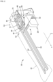
- Cooling mechanism 140 includes four heat pipes 142 and heat sink 144 for cooling the heat collected by heat pipes 142.
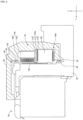
- cooling mechanism 140 will be described in detail with reference to figs. 6 and 7 in addition to fig. 5 .
- Each of the four heat pipes 142a, 142b, 142c, 142d is inserted, with one end thereof extending in the Y axis direction, between upper portion 124U of U-phase coil 122U and upper portion 124V of V-phase coil 122V, between upper portion 124V of V-phase coil 122V and upper portion 124W of W-phase coil 122W, between lower portion 125U of U-phase coil 122U and lower portion 125V of V-phase coil 122V, and between lower portion 125V of V-phase coil 122V and lower portion 125W of W-phase coil 122W.
- the one end of each of the four heat pipes 142 functions as a heat collector for absorbing the heat of coil 122.
- the one end of the four heat pipes 142 is sometimes referred to as heat collector 150.
- Heat collectors 150 of the four heat pipes 142 have a flat shape.
- the cross-sectional shape of heat collector 150 extending in the Y-axis direction is such that the dimension in the movement direction (X-axis direction) is smaller than the dimension in the direction perpendicular to the movement direction (Z direction). Accordingly, in X-direction moving device 52, which is the linear motor driven device of the present embodiment, even if heat collector 150 of heat pipes 142 is inserted between coils 122 of the respective phases in a state in direct contact with coils 122 so as to efficiently absorb heat, the size of the dimension in the movement direction of movable element 102 is curtailed.
- heat dissipator 152 which is the other end portion of each of the four heat pipes 132, protrudes from the head moving body 50 side (front side) portion of movable element 102, passes between stator 100a on the upper side and head attachment member 50, and extends above stator 100a.
- attachment plate 130 is formed with four vertically extending groove plates 154, and heat dissipators 152 of the four heat pipes 132 extend upward along groove 154 of attachment plate 130.
- Heat dissipators 152 of the four heat pipes 142 also have a flat shape.
- the cross-sectional shape of heat dissipator 152 is such that the dimension extending in the establishment direction (Y-axis direction) of the pair of stators 100 is smaller than the dimension in the direction (X-direction) perpendicular to that the direction.
- the cross-sectional shape of heat dissipator 152 extending in the Z-axis direction is such that the dimension (Y direction) perpendicular to the movement direction (X-direction) is smaller than the dimension in the movement direction.
- X-direction moving device 52 that is the linear motor driven device of the present embodiment is configured such that, even if four heat pipes 142 pass between the pair of stators 100 and head attachment body 50, the gap between the pair of stators 100 and head attachment body 50 is small, and the size of the dimension in the Y-axis direction including movable element 102 and head attachment body 50 is curtailed.
- each of the four heat pipes 142 has a shape in which the directions of the flat surfaces of heat collector 150 and heat dissipator 152 are different from each other.
- attachment plate 130 is made of aluminum having relatively high thermal conductivity, and receives heat from heat dissipators 152 of the four heat pipes 142 in contact with the attachment plate 130 so as to dissipate heat.
- heat sink 144 is provided at an upper end of attachment plate 130. More specifically, heat sink 144 includes fins 160 having multiple projections formed thereon, and fan 162 that air-cools fins 160, and fins 160 are fixed to the rear side of the upper end of attachment plate 130, and fan 162 is fixed to the rear side of fins 160.
- fan 162 which is a cooling device, is fixed to movable element 102 via attachment plate 130 in a state in which fan 162 is positioned on the upper of the pair of stators 100, stator 100a, that is, in a state on the upper side of upper stator 100a.
- the cooling mechanism In a cored T-type linear motor, it is common for the cooling mechanism to be arranged side-by-side with respect to the movable member in the establishment direction of the stator. In linear motor 56 of the present embodiment, if the cooling mechanism is provided behind movable element 102 in the Y-axis direction, the size of the cooling mechanism in the Y-axis direction including movable element 102 and head attachment body 50 increases.
- heat dissipator 152 of heat pipe 142 which is a cooling member, protrudes from the head moving body 50 side (front side) of movable element 102, passes between stator 100a on the upper side and head attachment body 50, and extends to the rear side of stator 100a, such that the size of the dimension in the Y-axis direction including movable element 102 and head attachment body 50 can be curtailed.
- X-direction moving device 52 which is the linear motor driven device of the present embodiment
- heat sink 144 including the cooling device is provided by using the space on the rear surface of one of the pair of stators, stator 100a
- the effect of cooling linear motor 56 is enhanced while curtailing the size of the dimension in the Y-axis direction including movable element 102 and head attachment body 50.
- fan 162 cannot be used in a magnetic field because a Hall sensor is used
- yoke 112 is disposed between multiple permanent magnets 110 and fan 162, fan 162 is not affected by the multiple permanent magnets 110, and malfunction or the like of fan 162 is prevented.
- the linear motor is oriented sideways, in other words, the establishment direction of the pair of stators is oriented sideways, but the establishment direction of the pair of stators may of course be a vertical direction.
Landscapes
- Engineering & Computer Science (AREA)
- Power Engineering (AREA)
- Physics & Mathematics (AREA)
- Chemical & Material Sciences (AREA)
- Combustion & Propulsion (AREA)
- Electromagnetism (AREA)
- Linear Motors (AREA)
- Motor Or Generator Cooling System (AREA)
Claims (8)
- Moteur linéaire (56) comprenant :une paire de stators (100a, 100b) prévus le long d'une direction de mouvement de manière à se faire mutuellement face ;un élément mobile (102) configuré pour se déplacer entre la paire de stators (100a, 100b) ;un élément de refroidissement (142) ayant (A) un collecteur de chaleur (150) prévu à l'intérieur de l'élément mobile (102) pour absorber la chaleur de l'élément mobile (102) ; et (B) un dissipateur de chaleur (152) faisant saillie vers l'extérieur depuis l'élément mobile (102), etdans lequel l'élément de refroidissement (142) est un caloduc (142) configuré de sorte qu'une extrémité de celui-ci soit insérée à l'intérieur de l'élément mobile (102) et fonctionne comme le collecteur de chaleur (150), et qu'une autre extrémité de celui-ci fasse saille vers l'extérieur de l'élément mobile (102) et fonctionne comme le dissipateur de chaleur (152),caractérisé en ce queladite autre extrémité du caloduc (142) qui fonctionne comme le dissipateur de chaleur (152) s'étend dans la direction dans laquelle la paire de stators (100a, 100b) se font mutuellement face vers un côté arrière de la paire de stators (100a, 100b), et présente une forme de section transversale dans laquelle une dimension dans une direction perpendiculaire à la direction de mouvement est inférieure à une dimension dans la direction de mouvement.
- Moteur linéaire (56) selon la revendication 1, comprenant en outre :
un dispositif de refroidissement (162) configuré pour refroidir ladite autre extrémité du caloduc (142) qui fonctionne comme le dissipateur de chaleur (152), et le dispositif de refroidissement (162) est fixé à l'élément mobile (102) tout en étant positionné sur le côté arrière de l'un de la paire de stators (100a, 100b). - Moteur linéaire (56) selon la revendication 2, comprenant en outre :une ailette (160) formée de multiples saillies et reliée à ladite autre extrémité du caloduc (142) qui fonctionne comme le dissipateur de chaleur (152),dans lequelle dispositif de refroidissement (162) est un ventilateur (162) configuré pour refroidir ladite autre extrémité du caloduc (142) qui fonctionne comme le dissipateur de chaleur (152) en refroidissant l'ailette (160) par air.
- Moteur linéaire (56) selon la revendication 3, dans lequelchacun de la paire de stators (100a, 100b) comprend une culasse (112) et de multiples aimants permanents fixés à la culasse (112), etl'ailette (160) est prévue sur une surface arrière de la culasse (112).
- Moteur linéaire (56) selon les revendications 1 à 4, dans lequel
le moteur linéaire (56) est configuré pour fonctionner avec un courant alternatif triphasé ayant trois phases : une phase U, une phase V et une phase W, et l'élément mobile (102) est configuré pour inclure plusieurs bobines (122U, 122V, 122W) correspondant à la phase U, à la phase V et à la phase W, et ladite extrémité du caloduc (142) qui fonctionne comme le collecteur de chaleur (150) est interposée entre les bobines (122U, 122V, 122W) de chaque phase. - Moteur linéaire (56) selon la revendication 5, dans lequel
les bobines (122U, 122V, 122W) de la phase U, de la phase V et de la phase W sont alignées dans la direction de mouvement, et ladite extrémité du caloduc (142) qui fonctionne comme le collecteur de chaleur (150) s'étend parallèlement à la paire de stators (100a, 100b) et présente une section transversale dans laquelle une dimension dans la direction de mouvement est inférieure à une dimension dans une direction perpendiculaire à la direction de mouvement. - Dispositif entraîné par un moteur linéaire (56) comprenant :un moteur linéaire (56) selon l'une quelconque des revendications 1 à 6 ;un corps de base (60) sur lequel sont établis la paire de stators (100a, 100b) ; etun corps mobile (50) prévu de manière mobile par rapport au corps de base (60) et fixé à l'élément mobile (102) dans un état adjacent à la paire de stators (100a, 100b) dans une direction d'établissement dans laquelle les stators (100a, 100b) sont établis,dans lequelladite autre extrémité du caloduc (142) qui fonctionne comme le dissipateur de chaleur (152) fait saillie depuis une partie côté corps mobile de l'élément mobile (102) et s'étend vers le côté arrière de la paire de stators (100a, 100b) à travers un espace entre l'un de la paire de stators (100a, 100b) et le corps mobile (50).
- Dispositif entraîné par un moteur linéaire (56) selon la revendication 7, dans lequella paire de stators (100a, 100b) sont établis de manière séparée l'un de l'autre dans une direction verticale,ladite autre extrémité du caloduc (142) qui fonctionne comme le dissipateur de chaleur (152) s'étend vers le haut, etle moteur linéaire (56) est pourvu d'un dispositif de refroidissement (162) fixé à l'élément mobile (102) dans état positionné au-dessus du stator supérieur de la paire de stators (100a, 100b) et configuré pour refroidir ladite autre extrémité du caloduc (142) qui fonctionne comme le dissipateur de chaleur (152).
Applications Claiming Priority (1)
| Application Number | Priority Date | Filing Date | Title |
|---|---|---|---|
| PCT/JP2017/029385 WO2019035181A1 (fr) | 2017-08-15 | 2017-08-15 | Moteur linéaire, dispositif entraîné par moteur linéaire et procédé de refroidissement de moteur linéaire |
Publications (3)
| Publication Number | Publication Date |
|---|---|
| EP3672045A1 EP3672045A1 (fr) | 2020-06-24 |
| EP3672045A4 EP3672045A4 (fr) | 2020-07-29 |
| EP3672045B1 true EP3672045B1 (fr) | 2025-06-04 |
Family
ID=65361862
Family Applications (1)
| Application Number | Title | Priority Date | Filing Date |
|---|---|---|---|
| EP17921786.4A Active EP3672045B1 (fr) | 2017-08-15 | 2017-08-15 | Moteur linéaire et dispositif entraîné par moteur linéaire |
Country Status (5)
| Country | Link |
|---|---|
| US (1) | US11424662B2 (fr) |
| EP (1) | EP3672045B1 (fr) |
| JP (1) | JP7223695B2 (fr) |
| CN (1) | CN111033987A (fr) |
| WO (1) | WO2019035181A1 (fr) |
Families Citing this family (2)
| Publication number | Priority date | Publication date | Assignee | Title |
|---|---|---|---|---|
| CN111095756B (zh) * | 2017-09-25 | 2022-06-14 | 株式会社富士 | 作业装置 |
| CN112701872B (zh) * | 2019-10-04 | 2022-06-14 | 台达电子工业股份有限公司 | 线性致动器 |
Citations (2)
| Publication number | Priority date | Publication date | Assignee | Title |
|---|---|---|---|---|
| WO2012145085A1 (fr) * | 2011-04-22 | 2012-10-26 | Continental Automotive Systems Us, Inc. | Oscillateur de puissance à réseau synchronisé doté d'inducteurs de branche |
| JP2013106497A (ja) * | 2011-11-16 | 2013-05-30 | Nippon Bearing Co Ltd | 直動装置 |
Family Cites Families (9)
| Publication number | Priority date | Publication date | Assignee | Title |
|---|---|---|---|---|
| TW465165B (en) * | 2000-03-03 | 2001-11-21 | Hiwin Mikrosystem Corp | A motor with heat pipe |
| JP2001327152A (ja) * | 2000-05-12 | 2001-11-22 | Yaskawa Electric Corp | リニアモータ |
| JP2002044928A (ja) * | 2000-07-21 | 2002-02-08 | Sodick Co Ltd | リニアモータ |
| WO2002043228A1 (fr) * | 2000-11-21 | 2002-05-30 | Kabushiki Kaisha Yaskawa Denki | Moteur lineaire |
| JP5426180B2 (ja) * | 2009-01-20 | 2014-02-26 | 富士機械製造株式会社 | リニアモータ |
| JP5252033B2 (ja) * | 2011-06-21 | 2013-07-31 | 東芝ホームテクノ株式会社 | 冷却ユニット |
| JP2013103497A (ja) * | 2011-11-14 | 2013-05-30 | 惠裕 ▲菅▼田 | ペン以外も保持できる多機能ペンケース |
| JP5901743B2 (ja) * | 2012-03-26 | 2016-04-13 | 富士機械製造株式会社 | リニアモータ装置 |
| EP2770253B1 (fr) * | 2013-02-26 | 2016-05-04 | Showa Denko K.K. | Appareil de rayonnement de chaleur pour éclairage à DEL |
-
2017
- 2017-08-15 JP JP2019536380A patent/JP7223695B2/ja active Active
- 2017-08-15 EP EP17921786.4A patent/EP3672045B1/fr active Active
- 2017-08-15 WO PCT/JP2017/029385 patent/WO2019035181A1/fr not_active Ceased
- 2017-08-15 CN CN201780093893.0A patent/CN111033987A/zh active Pending
- 2017-08-15 US US16/637,811 patent/US11424662B2/en active Active
Patent Citations (2)
| Publication number | Priority date | Publication date | Assignee | Title |
|---|---|---|---|---|
| WO2012145085A1 (fr) * | 2011-04-22 | 2012-10-26 | Continental Automotive Systems Us, Inc. | Oscillateur de puissance à réseau synchronisé doté d'inducteurs de branche |
| JP2013106497A (ja) * | 2011-11-16 | 2013-05-30 | Nippon Bearing Co Ltd | 直動装置 |
Also Published As
| Publication number | Publication date |
|---|---|
| EP3672045A1 (fr) | 2020-06-24 |
| WO2019035181A1 (fr) | 2019-02-21 |
| CN111033987A (zh) | 2020-04-17 |
| JP7223695B2 (ja) | 2023-02-16 |
| EP3672045A4 (fr) | 2020-07-29 |
| US20210152054A1 (en) | 2021-05-20 |
| US11424662B2 (en) | 2022-08-23 |
| JPWO2019035181A1 (ja) | 2020-07-30 |
Similar Documents
| Publication | Publication Date | Title |
|---|---|---|
| US8384253B2 (en) | Positioning system for positioning a positioning unit along a longitudinal axis | |
| JP5426180B2 (ja) | リニアモータ | |
| US9825508B2 (en) | Linear motor device | |
| JP5355105B2 (ja) | 直線駆動装置および電子回路部品装着機 | |
| JP6788664B2 (ja) | リニアモータ、ボイスコイルモータ、ステージ装置 | |
| US11424662B2 (en) | Linear motor, linear motor driven device, and method for cooling linear motor | |
| KR101282165B1 (ko) | 실장기 | |
| JP5901743B2 (ja) | リニアモータ装置 | |
| TWI505608B (zh) | Linear motors and platform devices | |
| EP2833508B1 (fr) | Appareil d'alimentation électrique sans contact | |
| JP5618725B2 (ja) | 電子部品装着装置 | |
| EP3657925B1 (fr) | Machine de montage de composants | |
| US20190111525A1 (en) | Actuator, mount head unit, mounting apparatus, and driving method of actuator | |
| JP4048557B2 (ja) | リニアモータの冷却装置 | |
| JP6851874B2 (ja) | リニアモータ駆動移動装置 | |
| KR102865183B1 (ko) | 다이 본딩 스테이지 | |
| JP2008177451A (ja) | 直動装置および電子部品実装装置 |
Legal Events
| Date | Code | Title | Description |
|---|---|---|---|
| STAA | Information on the status of an ep patent application or granted ep patent |
Free format text: STATUS: THE INTERNATIONAL PUBLICATION HAS BEEN MADE |
|
| PUAI | Public reference made under article 153(3) epc to a published international application that has entered the european phase |
Free format text: ORIGINAL CODE: 0009012 |
|
| STAA | Information on the status of an ep patent application or granted ep patent |
Free format text: STATUS: REQUEST FOR EXAMINATION WAS MADE |
|
| 17P | Request for examination filed |
Effective date: 20200214 |
|
| AK | Designated contracting states |
Kind code of ref document: A1 Designated state(s): AL AT BE BG CH CY CZ DE DK EE ES FI FR GB GR HR HU IE IS IT LI LT LU LV MC MK MT NL NO PL PT RO RS SE SI SK SM TR |
|
| AX | Request for extension of the european patent |
Extension state: BA ME |
|
| A4 | Supplementary search report drawn up and despatched |
Effective date: 20200701 |
|
| RIC1 | Information provided on ipc code assigned before grant |
Ipc: H02K 41/02 20060101AFI20200625BHEP Ipc: H02K 9/22 20060101ALI20200625BHEP |
|
| DAV | Request for validation of the european patent (deleted) | ||
| DAX | Request for extension of the european patent (deleted) | ||
| RIN1 | Information on inventor provided before grant (corrected) |
Inventor name: NOMURA, TAKESHI Inventor name: KATO, SHINICHI |
|
| STAA | Information on the status of an ep patent application or granted ep patent |
Free format text: STATUS: EXAMINATION IS IN PROGRESS |
|
| 17Q | First examination report despatched |
Effective date: 20220105 |
|
| P01 | Opt-out of the competence of the unified patent court (upc) registered |
Effective date: 20230328 |
|
| GRAP | Despatch of communication of intention to grant a patent |
Free format text: ORIGINAL CODE: EPIDOSNIGR1 |
|
| STAA | Information on the status of an ep patent application or granted ep patent |
Free format text: STATUS: GRANT OF PATENT IS INTENDED |
|
| INTG | Intention to grant announced |
Effective date: 20250113 |
|
| GRAS | Grant fee paid |
Free format text: ORIGINAL CODE: EPIDOSNIGR3 |
|
| GRAA | (expected) grant |
Free format text: ORIGINAL CODE: 0009210 |
|
| STAA | Information on the status of an ep patent application or granted ep patent |
Free format text: STATUS: THE PATENT HAS BEEN GRANTED |
|
| AK | Designated contracting states |
Kind code of ref document: B1 Designated state(s): AL AT BE BG CH CY CZ DE DK EE ES FI FR GB GR HR HU IE IS IT LI LT LU LV MC MK MT NL NO PL PT RO RS SE SI SK SM TR |
|
| REG | Reference to a national code |
Ref country code: GB Ref legal event code: FG4D |
|
| REG | Reference to a national code |
Ref country code: CH Ref legal event code: EP |
|
| REG | Reference to a national code |
Ref country code: DE Ref legal event code: R096 Ref document number: 602017089841 Country of ref document: DE |
|
| REG | Reference to a national code |
Ref country code: IE Ref legal event code: FG4D |
|
| REG | Reference to a national code |
Ref country code: NL Ref legal event code: MP Effective date: 20250604 |
|
| PG25 | Lapsed in a contracting state [announced via postgrant information from national office to epo] |
Ref country code: FI Free format text: LAPSE BECAUSE OF FAILURE TO SUBMIT A TRANSLATION OF THE DESCRIPTION OR TO PAY THE FEE WITHIN THE PRESCRIBED TIME-LIMIT Effective date: 20250604 Ref country code: ES Free format text: LAPSE BECAUSE OF FAILURE TO SUBMIT A TRANSLATION OF THE DESCRIPTION OR TO PAY THE FEE WITHIN THE PRESCRIBED TIME-LIMIT Effective date: 20250604 |
|
| PGFP | Annual fee paid to national office [announced via postgrant information from national office to epo] |
Ref country code: DE Payment date: 20250702 Year of fee payment: 9 |
|
| REG | Reference to a national code |
Ref country code: LT Ref legal event code: MG9D |
|
| PG25 | Lapsed in a contracting state [announced via postgrant information from national office to epo] |
Ref country code: GR Free format text: LAPSE BECAUSE OF FAILURE TO SUBMIT A TRANSLATION OF THE DESCRIPTION OR TO PAY THE FEE WITHIN THE PRESCRIBED TIME-LIMIT Effective date: 20250905 Ref country code: NO Free format text: LAPSE BECAUSE OF FAILURE TO SUBMIT A TRANSLATION OF THE DESCRIPTION OR TO PAY THE FEE WITHIN THE PRESCRIBED TIME-LIMIT Effective date: 20250904 |
|
| PG25 | Lapsed in a contracting state [announced via postgrant information from national office to epo] |
Ref country code: PL Free format text: LAPSE BECAUSE OF FAILURE TO SUBMIT A TRANSLATION OF THE DESCRIPTION OR TO PAY THE FEE WITHIN THE PRESCRIBED TIME-LIMIT Effective date: 20250604 |
|
| PG25 | Lapsed in a contracting state [announced via postgrant information from national office to epo] |
Ref country code: BG Free format text: LAPSE BECAUSE OF FAILURE TO SUBMIT A TRANSLATION OF THE DESCRIPTION OR TO PAY THE FEE WITHIN THE PRESCRIBED TIME-LIMIT Effective date: 20250604 |
|
| PG25 | Lapsed in a contracting state [announced via postgrant information from national office to epo] |
Ref country code: HR Free format text: LAPSE BECAUSE OF FAILURE TO SUBMIT A TRANSLATION OF THE DESCRIPTION OR TO PAY THE FEE WITHIN THE PRESCRIBED TIME-LIMIT Effective date: 20250604 |
|
| PG25 | Lapsed in a contracting state [announced via postgrant information from national office to epo] |
Ref country code: RS Free format text: LAPSE BECAUSE OF FAILURE TO SUBMIT A TRANSLATION OF THE DESCRIPTION OR TO PAY THE FEE WITHIN THE PRESCRIBED TIME-LIMIT Effective date: 20250904 |
|
| PG25 | Lapsed in a contracting state [announced via postgrant information from national office to epo] |
Ref country code: LV Free format text: LAPSE BECAUSE OF FAILURE TO SUBMIT A TRANSLATION OF THE DESCRIPTION OR TO PAY THE FEE WITHIN THE PRESCRIBED TIME-LIMIT Effective date: 20250604 |
|
| PG25 | Lapsed in a contracting state [announced via postgrant information from national office to epo] |
Ref country code: NL Free format text: LAPSE BECAUSE OF FAILURE TO SUBMIT A TRANSLATION OF THE DESCRIPTION OR TO PAY THE FEE WITHIN THE PRESCRIBED TIME-LIMIT Effective date: 20250604 |
|
| PG25 | Lapsed in a contracting state [announced via postgrant information from national office to epo] |
Ref country code: PT Free format text: LAPSE BECAUSE OF FAILURE TO SUBMIT A TRANSLATION OF THE DESCRIPTION OR TO PAY THE FEE WITHIN THE PRESCRIBED TIME-LIMIT Effective date: 20251006 |
|
| REG | Reference to a national code |
Ref country code: AT Ref legal event code: MK05 Ref document number: 1801355 Country of ref document: AT Kind code of ref document: T Effective date: 20250604 |
|
| PG25 | Lapsed in a contracting state [announced via postgrant information from national office to epo] |
Ref country code: IS Free format text: LAPSE BECAUSE OF FAILURE TO SUBMIT A TRANSLATION OF THE DESCRIPTION OR TO PAY THE FEE WITHIN THE PRESCRIBED TIME-LIMIT Effective date: 20251004 |
|
| PG25 | Lapsed in a contracting state [announced via postgrant information from national office to epo] |
Ref country code: SM Free format text: LAPSE BECAUSE OF FAILURE TO SUBMIT A TRANSLATION OF THE DESCRIPTION OR TO PAY THE FEE WITHIN THE PRESCRIBED TIME-LIMIT Effective date: 20250604 Ref country code: AT Free format text: LAPSE BECAUSE OF FAILURE TO SUBMIT A TRANSLATION OF THE DESCRIPTION OR TO PAY THE FEE WITHIN THE PRESCRIBED TIME-LIMIT Effective date: 20250604 |
|
| PG25 | Lapsed in a contracting state [announced via postgrant information from national office to epo] |
Ref country code: CZ Free format text: LAPSE BECAUSE OF FAILURE TO SUBMIT A TRANSLATION OF THE DESCRIPTION OR TO PAY THE FEE WITHIN THE PRESCRIBED TIME-LIMIT Effective date: 20250604 |
|
| PG25 | Lapsed in a contracting state [announced via postgrant information from national office to epo] |
Ref country code: EE Free format text: LAPSE BECAUSE OF FAILURE TO SUBMIT A TRANSLATION OF THE DESCRIPTION OR TO PAY THE FEE WITHIN THE PRESCRIBED TIME-LIMIT Effective date: 20250604 |
|
| PG25 | Lapsed in a contracting state [announced via postgrant information from national office to epo] |
Ref country code: RO Free format text: LAPSE BECAUSE OF FAILURE TO SUBMIT A TRANSLATION OF THE DESCRIPTION OR TO PAY THE FEE WITHIN THE PRESCRIBED TIME-LIMIT Effective date: 20250604 Ref country code: SK Free format text: LAPSE BECAUSE OF FAILURE TO SUBMIT A TRANSLATION OF THE DESCRIPTION OR TO PAY THE FEE WITHIN THE PRESCRIBED TIME-LIMIT Effective date: 20250604 |
|
| PG25 | Lapsed in a contracting state [announced via postgrant information from national office to epo] |
Ref country code: IT Free format text: LAPSE BECAUSE OF FAILURE TO SUBMIT A TRANSLATION OF THE DESCRIPTION OR TO PAY THE FEE WITHIN THE PRESCRIBED TIME-LIMIT Effective date: 20250604 |
|
| REG | Reference to a national code |
Ref country code: DE Ref legal event code: R097 Ref document number: 602017089841 Country of ref document: DE |
|
| REG | Reference to a national code |
Ref country code: CH Ref legal event code: H13 Free format text: ST27 STATUS EVENT CODE: U-0-0-H10-H13 (AS PROVIDED BY THE NATIONAL OFFICE) Effective date: 20260324 |
|
| PG25 | Lapsed in a contracting state [announced via postgrant information from national office to epo] |
Ref country code: MC Free format text: LAPSE BECAUSE OF FAILURE TO SUBMIT A TRANSLATION OF THE DESCRIPTION OR TO PAY THE FEE WITHIN THE PRESCRIBED TIME-LIMIT Effective date: 20250604 |
|
| PLBE | No opposition filed within time limit |
Free format text: ORIGINAL CODE: 0009261 |
|
| STAA | Information on the status of an ep patent application or granted ep patent |
Free format text: STATUS: NO OPPOSITION FILED WITHIN TIME LIMIT |
|
| PG25 | Lapsed in a contracting state [announced via postgrant information from national office to epo] |
Ref country code: DK Free format text: LAPSE BECAUSE OF FAILURE TO SUBMIT A TRANSLATION OF THE DESCRIPTION OR TO PAY THE FEE WITHIN THE PRESCRIBED TIME-LIMIT Effective date: 20250604 |
|
| PG25 | Lapsed in a contracting state [announced via postgrant information from national office to epo] |
Ref country code: LU Free format text: LAPSE BECAUSE OF NON-PAYMENT OF DUE FEES Effective date: 20250815 |
|
| REG | Reference to a national code |
Ref country code: CH Ref legal event code: L10 Free format text: ST27 STATUS EVENT CODE: U-0-0-L10-L00 (AS PROVIDED BY THE NATIONAL OFFICE) Effective date: 20260416 |
|
| PG25 | Lapsed in a contracting state [announced via postgrant information from national office to epo] |
Ref country code: CH Free format text: LAPSE BECAUSE OF NON-PAYMENT OF DUE FEES Effective date: 20250831 |
|
| 26N | No opposition filed |
Effective date: 20260305 |