EP3672087B1 - Netzwerksteuerungseinheit mit leistungsverstärkerblöcken und flugzeug mit solch einer netzwerksteuerungseinheit - Google Patents
Netzwerksteuerungseinheit mit leistungsverstärkerblöcken und flugzeug mit solch einer netzwerksteuerungseinheit Download PDFInfo
- Publication number
- EP3672087B1 EP3672087B1 EP19217397.9A EP19217397A EP3672087B1 EP 3672087 B1 EP3672087 B1 EP 3672087B1 EP 19217397 A EP19217397 A EP 19217397A EP 3672087 B1 EP3672087 B1 EP 3672087B1
- Authority
- EP
- European Patent Office
- Prior art keywords
- power amplifier
- control unit
- network control
- port
- designed
- Prior art date
- Legal status (The legal status is an assumption and is not a legal conclusion. Google has not performed a legal analysis and makes no representation as to the accuracy of the status listed.)
- Active
Links
Images

Classifications
-
- H—ELECTRICITY
- H04—ELECTRIC COMMUNICATION TECHNIQUE
- H04B—TRANSMISSION
- H04B1/00—Details of transmission systems, not covered by a single one of groups H04B3/00 - H04B13/00; Details of transmission systems not characterised by the medium used for transmission
- H04B1/02—Transmitters
- H04B1/04—Circuits
- H04B1/0458—Arrangements for matching and coupling between power amplifier and antenna or between amplifying stages
-
- H—ELECTRICITY
- H01—ELECTRIC ELEMENTS
- H01P—WAVEGUIDES; RESONATORS, LINES, OR OTHER DEVICES OF THE WAVEGUIDE TYPE
- H01P1/00—Auxiliary devices
- H01P1/20—Frequency-selective devices, e.g. filters
- H01P1/213—Frequency-selective devices, e.g. filters combining or separating two or more different frequencies
-
- H—ELECTRICITY
- H04—ELECTRIC COMMUNICATION TECHNIQUE
- H04K—SECRET COMMUNICATION; JAMMING OF COMMUNICATION
- H04K3/00—Jamming of communication; Counter-measures
- H04K3/20—Countermeasures against jamming
- H04K3/28—Countermeasures against jamming with jamming and anti-jamming mechanisms both included in a same device or system, e.g. wherein anti-jamming includes prevention of undesired self-jamming resulting from jamming
-
- H—ELECTRICITY
- H04—ELECTRIC COMMUNICATION TECHNIQUE
- H04K—SECRET COMMUNICATION; JAMMING OF COMMUNICATION
- H04K3/00—Jamming of communication; Counter-measures
- H04K3/40—Jamming having variable characteristics
- H04K3/42—Jamming having variable characteristics characterized by the control of the jamming frequency or wavelength
-
- H—ELECTRICITY
- H04—ELECTRIC COMMUNICATION TECHNIQUE
- H04K—SECRET COMMUNICATION; JAMMING OF COMMUNICATION
- H04K3/00—Jamming of communication; Counter-measures
- H04K3/40—Jamming having variable characteristics
- H04K3/43—Jamming having variable characteristics characterized by the control of the jamming power, signal-to-noise ratio or geographic coverage area
-
- H—ELECTRICITY
- H04—ELECTRIC COMMUNICATION TECHNIQUE
- H04W—WIRELESS COMMUNICATION NETWORKS
- H04W48/00—Access restriction; Network selection; Access point selection
- H04W48/02—Access restriction performed under specific conditions
-
- H—ELECTRICITY
- H04—ELECTRIC COMMUNICATION TECHNIQUE
- H04B—TRANSMISSION
- H04B1/00—Details of transmission systems, not covered by a single one of groups H04B3/00 - H04B13/00; Details of transmission systems not characterised by the medium used for transmission
- H04B1/02—Transmitters
- H04B1/04—Circuits
- H04B1/0483—Transmitters with multiple parallel paths
-
- H—ELECTRICITY
- H04—ELECTRIC COMMUNICATION TECHNIQUE
- H04B—TRANSMISSION
- H04B1/00—Details of transmission systems, not covered by a single one of groups H04B3/00 - H04B13/00; Details of transmission systems not characterised by the medium used for transmission
- H04B1/02—Transmitters
- H04B1/04—Circuits
- H04B2001/0408—Circuits with power amplifiers
-
- H—ELECTRICITY
- H04—ELECTRIC COMMUNICATION TECHNIQUE
- H04K—SECRET COMMUNICATION; JAMMING OF COMMUNICATION
- H04K2203/00—Jamming of communication; Countermeasures
- H04K2203/10—Jamming or countermeasure used for a particular application
- H04K2203/16—Jamming or countermeasure used for a particular application for telephony
-
- H—ELECTRICITY
- H04—ELECTRIC COMMUNICATION TECHNIQUE
- H04K—SECRET COMMUNICATION; JAMMING OF COMMUNICATION
- H04K2203/00—Jamming of communication; Countermeasures
- H04K2203/10—Jamming or countermeasure used for a particular application
- H04K2203/22—Jamming or countermeasure used for a particular application for communication related to vehicles
-
- H—ELECTRICITY
- H04—ELECTRIC COMMUNICATION TECHNIQUE
- H04K—SECRET COMMUNICATION; JAMMING OF COMMUNICATION
- H04K2203/00—Jamming of communication; Countermeasures
- H04K2203/30—Jamming or countermeasure characterized by the infrastructure components
- H04K2203/34—Jamming or countermeasure characterized by the infrastructure components involving multiple cooperating jammers
-
- Y—GENERAL TAGGING OF NEW TECHNOLOGICAL DEVELOPMENTS; GENERAL TAGGING OF CROSS-SECTIONAL TECHNOLOGIES SPANNING OVER SEVERAL SECTIONS OF THE IPC; TECHNICAL SUBJECTS COVERED BY FORMER USPC CROSS-REFERENCE ART COLLECTIONS [XRACs] AND DIGESTS
- Y02—TECHNOLOGIES OR APPLICATIONS FOR MITIGATION OR ADAPTATION AGAINST CLIMATE CHANGE
- Y02D—CLIMATE CHANGE MITIGATION TECHNOLOGIES IN INFORMATION AND COMMUNICATION TECHNOLOGIES [ICT], I.E. INFORMATION AND COMMUNICATION TECHNOLOGIES AIMING AT THE REDUCTION OF THEIR OWN ENERGY USE
- Y02D30/00—Reducing energy consumption in communication networks
- Y02D30/70—Reducing energy consumption in communication networks in wireless communication networks
Definitions
- the invention relates to a network control unit with power amplifier blocks and an aircraft comprising such a network control unit.
- the invention applies more particularly to a network control unit comprising:
- a network control unit is used in aircrafts to mask cellular ground base transceiver stations from passenger equipment like cell phones, transmitting personal electronic devices, etc. To achieve this, the NCU emits noise signals on different frequency bands used by the cellular ground base transceiver stations.
- the NCU Because space is scarce in an airplane, the NCU must be compact. This can lead to put together the power amplifier blocks on one mounting frame with limited dimensions, which can lead to instabilities or unwanted oscillations. To prevent these unwanted oscillations, it is known to install absorber pads at predefined positions in the vicinity of the power amplifier blocks. However, these absorber pads use a significant amount of space.
- An object of the invention is therefore a network control unit comprising:
- the use of the circulator prevents their appearance, so that less absorber pads, and sometimes even no absorber pads, are needed. More precisely, the use of the circulator allows redirecting a return signal so that it does not reach the power amplifier and does not cause the unwanted oscillations.
- the network control unit comprises, for each of the power amplifiers, a circulator connected between the power amplifier and the multi-band combiner.
- the circulator comprises a first port connected to the power amplifier block, a second port connected to the multi-band combiner and a third port, and is designed such that the noise signal entering the first port is provided to the second port and such that a return signal entering the second port is provided to the third port, and the network control unit further comprises a matched load connected to the third port.
- the network control unit comprises, for at least one power amplifier block, a band-pass filter connected between the noise generation unit and the power amplifier.
- the band-pass filter is a ceramic band-pass filter.
- the network control unit comprises a current monitoring system for monitoring currents respectively outputted by the power amplifier blocks.
- each power amplifier block is designed for providing the respective noise signal at a power of at least 10 dBm.
- each power amplifier block is designed for being controlled to provide the respective noise signal at a power between 10 dBm and 30 dBm.
- the power amplifier blocks are designed for being controlled to be selectively activated and deactivated independently one from another.
- Another object of the invention is an aircraft comprising a network control unit according to the invention.
- NCU network control unit
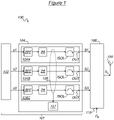
- the NCU 100 comprises a noise generation system 101 for generating noise signals S1, S2, S3 in respective frequency bands.
- the noise generation system 101 comprises a digital noise generation unit 102 for generating low power noise signals s1, s2, s3 in the respective frequency bands.
- the digital noise generation unit 102 is designed for generating three low power noise signals s1, s2, s3 in respectively the three following frequency bands: (NB700) 728 - 844 MHz, (NB900) 925 - 960 MHz and (NB2100) 2110 - 2170 MHz. It will be noted that these frequency bands are each wideband, that is to say that they each extend over more than 20 MHz. It will also be noted that at least one frequency band extends over more than 100 MHz.
- the digital noise generation unit 102 is for example as described in patent US 8 159 280 B2 .
- the noise generation system 101 further comprises a power amplifier stage 104 comprising power amplifiers 104A, 104B, 104C for respectively amplifying the low power noise signals s1, s2, s3 in order to provide the noise signals S1, S2, S3.
- a power amplifier stage 104 comprising power amplifiers 104A, 104B, 104C for respectively amplifying the low power noise signals s1, s2, s3 in order to provide the noise signals S1, S2, S3.
- Each power amplifier 104A, 104B, 104C is designed to provide a predefined amplification factor over the whole respective frequency band.
- the power amplifier 104A is designed to provide a predefined amplification factor over the frequency band (NB700) 728 - 844 MHz. Because the frequency bands are wideband, the power amplifiers 104A, 104B, 104C are wideband amplifiers.
- Each power amplifier 104A, 104B, 104C comprises a band-pass filter BPF designed for filtering the low power noise signals s1, s2, s3.
- each band-pass filter BPF is a ceramic band-pass filter BPF.
- Each power amplifier 104A, 104B, 104C further comprises a power amplifier block PA designed for amplifying the filtered low power noise signal s1, s2, s3 into the respective noise signal S1, S2, S3 outputted by the power amplifier 104A, 104B, 104C.
- Each power amplifier block PA is designed for providing the respective noise signal S1, S2, S3 at a power of at least 10 dBm. More precisely, in the described example, each power amplifier block PA is designed for being controlled to provide the respective noise signal S1, S2, S3 at a power between 10 dBm and 30 dBm.
- the power amplifier blocks PA are designed for being controlled to be selectively activated and deactivated independently one from another.
- Each power amplifier 104A, 104B, 104C further comprises an isolator ISOL connected to an output OUT of the power amplifier 104A, 104B, 104C and designed for preventing signals from being reflected back to the power amplifier block PA.
- the isolator ISOL will be described in greater detail below, with reference to figure 2 .
- the NCU further comprises a current monitoring system 105 designed for monitoring currents respectively outputted by the power amplifier blocks PA of the power amplifiers 104A, 104B, 104C.
- the current monitoring system 105 is used to observe the current of each power amplifier block PA to get information about operation of a transistor of this power amplifier block PA through aging, temperature, voltage, etc., and therefore possible radiofrequency performance degradation. If a power amplifier monitoring system 107 detects that a first threshold is reached (for example, under conditions defined in a requirement specification and nominal radiofrequency output power), this power amplifier monitoring system 107 generates a current alarm, indicating a possible RF performance degradation.
- Each power amplifier 104A, 104B, 104C can be switched off individually, for example, for power saving, one of several of the power amplifiers can be switched off when not used.
- Each power amplifier 104A, 104B, 104C preferably further comprises an integrated current sensor (not shown on the figures) and an hardware defined second threshold.
- the integrated current sensor is designed for disabling this power amplifier 104A, 104B, 104C when the sensed current reaches this second threshold, which is indicative of erroneous operation of the power amplifier 104A, 104B, 104C (e.g. oscillation, short circuit, ).
- This second threshold is much higher than the first threshold set for alarm monitoring.
- the current monitoring system 105 can be used instead of the integrated current sensors.
- the NCU 100 further comprises a multi-band combiner 106 connected to the outputs OUT of the power amplifiers 104A, 104B, 104C and designed for filtering and summing the noise signals S1, S2, S3 and, optionally, a base signal S B provided for example by a base transceiver station (BTS), a node or a enode of the aircraft, into a single output signal S O to be provided to an antenna 109.
- BTS base transceiver station
- the multi-band combiner 106 comprises an input 110.
- the isolator ISOL of the first power amplifier 104A will now be described.
- the isolators ISOL of the other two power amplifiers 104B, 104C are identical.
- the isolator ISOL comprises a circulator 202 comprising a first port P1 connected to the power amplifier block PA, a second port P2 connected to the output of the power amplifier 104A and a third port P3.
- the circulator 202 is designed such that the noise signal entering the first port P1 is provided to the second port P2 and such that a return signal entering the second port P2 is provided to the third port P3.
- the isolator ISOL further comprises a matched load 204 connected to the third port P3.
- the load (formed by the multi-band combiner 106) connected to the output OUT of the power amplifier 104A, 104B, 104C is often mismatched with respect to the transmission line (formed by the power amplifier 104A, 104B, 104C), so that part of the noise signal S3 is reflected back as a return signal and enters the output OUT of the power amplifier 104A, 104B, 104C.
- the return signal is directed to the matched load 204, which absorbs it. In this manner, the isolator ISOL prevents the return signal from going back to the power amplifier block PA, and therefore decreases the risk of unwanted oscillations in the power amplifier 104A, 104B, 104C.
- the circulator 202 used in the power amplifiers 104A, 104B for frequency bands below 1 GHz has a bandwidth wider than the circulator 202 used in the power amplifier 104C for frequency band around 2 GHz (i.e. NB2100).
Landscapes
- Engineering & Computer Science (AREA)
- Computer Networks & Wireless Communication (AREA)
- Signal Processing (AREA)
- Radar, Positioning & Navigation (AREA)
- Remote Sensing (AREA)
- Computer Security & Cryptography (AREA)
- Amplifiers (AREA)
- Transmitters (AREA)
- Input Circuits Of Receivers And Coupling Of Receivers And Audio Equipment (AREA)
- Noise Elimination (AREA)
Claims (10)
- Netzwerksteuerungseinheit (100) umfassend:- eine Rauscherzeugungseinheit (102) zum Erzeugen von Rauschsignalen mit geringer Leistung (s1, s2, s3) in den jeweiligen Frequenzbändern;- Leistungsverstärkerblöcke (PA) zum jeweiligen Verstärken der Rauschsignale mit geringer Leistung (s1, s2, s3) in Rauschsignale (S1, S2, S3); und- einen Multibandkombinierer (106), der dazu ausgelegt ist, die Rauschsignale (S1, S2, S3) zu einem einzigen Ausgangssignal (So) zu summieren, das einer Antenne (109) zugeführt wird;dadurch gekennzeichnet, dass die Netzwerksteuerungseinheit (100) ferner für mindestens einen der Leistungsverstärkerblöcke (PA) einen Zirkulator (202) umfasst, der zwischen diesen Leistungsverstärkerblock (PA) und den Multibandkombinierer (106) geschaltet ist.
- Netzwerksteuerungseinheit (100) nach Anspruch 1, wobei die Netzwerksteuerungseinheit (100) für jeden der Leistungsverstärkerblöcke (PA) einen Zirkulator (202) umfasst, der zwischen den Leistungsverstärkerblock (PA) und den Multibandkombinierer (106) geschaltet ist.
- Netzwerksteuerungseinheit (100) nach Anspruch 1 oder 2, wobei der Zirkulator (202) einen ersten Anschluss (P1), der mit dem Leistungsverstärkerblock (PA) verbunden ist, einen zweiten Anschluss (P2), der mit dem Multibandkombinierer (106) verbunden ist, und einen dritten Anschluss (P3) umfasst und so ausgelegt ist, dass das in den ersten Anschluss (P1) eintretende Rauschsignal (S1, S2, S3) dem zweiten Anschluss (P2) zugeführt wird, und so, dass ein in den zweiten Anschluss (P2) eintretendes Rücksignal dem dritten Anschluss (P3) zugeführt wird, und ferner umfassend eine angepasste Last (204), die mit dem dritten Anschluss (P3) verbunden ist.
- Netzwerksteuerungseinheit (100) nach einem der Ansprüche 1 bis 3, umfassend, für mindestens einen Leistungsverstärkerblock (PA), einen Bandpassfilter (BPF), der zwischen die Rauscherzeugungseinheit (102) und den Leistungsverstärkerblock (PA) geschaltet ist.
- Netzwerksteuerungseinheit (100) nach Anspruch 4, wobei der Bandpassfilter ein keramischer Bandpassfilter (BPF) ist.
- Netzwerksteuerungseinheit (100) nach einem der Ansprüche 1 bis 5, ferner umfassend ein Stromüberwachungssystem (105) zum Überwachen von Strömen, die jeweils von den Leistungsverstärkerblöcken (PA) ausgegeben werden.
- Netzwerksteuerungseinheit (100) nach einem der Ansprüche 1 bis 6, wobei jeder Leistungsverstärkerblock (PA) dazu ausgelegt ist, das jeweilige Rauschsignal (S1, S2, S3) mit einer Leistung von mindestens 10 dBm bereitzustellen.
- Netzwerksteuerungseinheit (100) nach Anspruch 7, wobei jeder Leistungsverstärkerblock (PA) dazu ausgelegt ist, gesteuert zu werden, um das jeweilige Rauschsignal (S1, S2, S3) mit einer Leistung zwischen 10 dBm und 30 dBm bereitzustellen.
- Netzwerksteuerungseinheit (100) nach einem der Ansprüche 1 bis 8, wobei die Leistungsverstärkerblöcke (PA) dazu ausgelegt sind, unabhängig voneinander selektiv aktiviert und deaktiviert zu werden.
- Luftfahrzeug, umfassend eine Netzwerksteuerungseinheit (100) nach einem der Ansprüche 1 bis 9.
Applications Claiming Priority (1)
| Application Number | Priority Date | Filing Date | Title |
|---|---|---|---|
| EP18215643 | 2018-12-21 |
Publications (2)
| Publication Number | Publication Date |
|---|---|
| EP3672087A1 EP3672087A1 (de) | 2020-06-24 |
| EP3672087B1 true EP3672087B1 (de) | 2022-05-18 |
Family
ID=67436978
Family Applications (2)
| Application Number | Title | Priority Date | Filing Date |
|---|---|---|---|
| EP19217397.9A Active EP3672087B1 (de) | 2018-12-21 | 2019-12-18 | Netzwerksteuerungseinheit mit leistungsverstärkerblöcken und flugzeug mit solch einer netzwerksteuerungseinheit |
| EP19217384.7A Active EP3671947B1 (de) | 2018-12-21 | 2019-12-18 | Netzwerksteuereinheit mit einem mehrbandkombinierer und flugzeug mit einer solchen netzwerksteuereinheit |
Family Applications After (1)
| Application Number | Title | Priority Date | Filing Date |
|---|---|---|---|
| EP19217384.7A Active EP3671947B1 (de) | 2018-12-21 | 2019-12-18 | Netzwerksteuereinheit mit einem mehrbandkombinierer und flugzeug mit einer solchen netzwerksteuereinheit |
Country Status (1)
| Country | Link |
|---|---|
| EP (2) | EP3672087B1 (de) |
Families Citing this family (1)
| Publication number | Priority date | Publication date | Assignee | Title |
|---|---|---|---|---|
| EP4080773A1 (de) * | 2021-04-19 | 2022-10-26 | Siemens Aktiengesellschaft | Hochfrequenz-filter |
Family Cites Families (4)
| Publication number | Priority date | Publication date | Assignee | Title |
|---|---|---|---|---|
| DE102009004577B4 (de) * | 2009-01-14 | 2010-11-25 | Siemens Ag Österreich | Rauschgenerator zur Erzeugung eines bandbegrenzten Rauschens, dessen Zeitsignal einen niedrigen Crest-Faktor aufweist |
| CA2772428A1 (en) * | 2009-08-31 | 2011-03-03 | Huawei Technologies Co., Ltd. | Method and device for duplexer fault detection |
| CN103684654B (zh) * | 2013-12-17 | 2017-07-28 | 中电科航空电子有限公司 | 民航客机客舱内蜂窝移动通信射频信号干扰装置 |
| US10044375B2 (en) * | 2015-01-30 | 2018-08-07 | Telefonaktiebolaget Lm Ericsson (Publ) | Multiband transmitter circuit with integrated circulators and filters |
-
2019
- 2019-12-18 EP EP19217397.9A patent/EP3672087B1/de active Active
- 2019-12-18 EP EP19217384.7A patent/EP3671947B1/de active Active
Also Published As
| Publication number | Publication date |
|---|---|
| EP3672087A1 (de) | 2020-06-24 |
| EP3671947B1 (de) | 2024-05-01 |
| EP3671947A1 (de) | 2020-06-24 |
Similar Documents
| Publication | Publication Date | Title |
|---|---|---|
| US10623171B2 (en) | Transmission and reception module for a plurality of frequency bands | |
| JP4301401B2 (ja) | フロントエンドモジュール及び通信端末 | |
| US10069576B2 (en) | Interference suppression system and method | |
| US10483928B2 (en) | Power amplification module | |
| WO2016178070A1 (en) | Distributed duplexer configuration for blocking and linearity | |
| JP2006186596A (ja) | アンテナ共用装置およびそれを用いた無線通信端末 | |
| US20180109274A1 (en) | High-frequency front-end circuit | |
| TW202121854A (zh) | 多頻帶低雜訊放大模組 | |
| US10069523B2 (en) | Power amplification module | |
| WO2015001828A1 (ja) | フロントエンド回路 | |
| JP5638468B2 (ja) | 信号切替装置 | |
| US7054600B2 (en) | Channel-selective amplifier with tunable filter | |
| JP2010035158A (ja) | 送信回路及び送信回路を用いた通信機器 | |
| KR101400739B1 (ko) | 무전기 간섭신호 제거 장치 | |
| EP3672087A1 (de) | Netzwerksteuerungseinheit mit leistungsverstärkerblöcken und flugzeug mit solch einer netzwerksteuerungseinheit | |
| US10439662B2 (en) | Mobile radio compensator for use in motor vehicles, and a motor vehicle of this kind | |
| US10211879B2 (en) | Front-end module | |
| EP3499745B1 (de) | An einem turm montierter verstärker | |
| JP2006197368A (ja) | マルチモード通信装置 | |
| JP2009278225A (ja) | 無線通信装置 | |
| JP2008205821A (ja) | 高周波電力増幅装置及びそれを用いた送信装置 | |
| WO2019021841A1 (ja) | 高周波回路及び通信装置 | |
| KR101855166B1 (ko) | 단일 입력 다중 출력 구조를 갖는 증폭 장치 | |
| KR101102068B1 (ko) | Wcdma 및 wibro 기반 iss 중계기 | |
| WO2020226119A1 (ja) | 高周波回路および通信装置 |
Legal Events
| Date | Code | Title | Description |
|---|---|---|---|
| PUAI | Public reference made under article 153(3) epc to a published international application that has entered the european phase |
Free format text: ORIGINAL CODE: 0009012 |
|
| STAA | Information on the status of an ep patent application or granted ep patent |
Free format text: STATUS: THE APPLICATION HAS BEEN PUBLISHED |
|
| AK | Designated contracting states |
Kind code of ref document: A1 Designated state(s): AL AT BE BG CH CY CZ DE DK EE ES FI FR GB GR HR HU IE IS IT LI LT LU LV MC MK MT NL NO PL PT RO RS SE SI SK SM TR |
|
| AX | Request for extension of the european patent |
Extension state: BA ME |
|
| STAA | Information on the status of an ep patent application or granted ep patent |
Free format text: STATUS: REQUEST FOR EXAMINATION WAS MADE |
|
| 17P | Request for examination filed |
Effective date: 20201217 |
|
| RBV | Designated contracting states (corrected) |
Designated state(s): AL AT BE BG CH CY CZ DE DK EE ES FI FR GB GR HR HU IE IS IT LI LT LU LV MC MK MT NL NO PL PT RO RS SE SI SK SM TR |
|
| GRAP | Despatch of communication of intention to grant a patent |
Free format text: ORIGINAL CODE: EPIDOSNIGR1 |
|
| STAA | Information on the status of an ep patent application or granted ep patent |
Free format text: STATUS: GRANT OF PATENT IS INTENDED |
|
| RIC1 | Information provided on ipc code assigned before grant |
Ipc: H04W 48/02 20090101ALI20211220BHEP Ipc: H04K 3/00 20060101ALI20211220BHEP Ipc: H04B 1/04 20060101AFI20211220BHEP |
|
| INTG | Intention to grant announced |
Effective date: 20220124 |
|
| GRAS | Grant fee paid |
Free format text: ORIGINAL CODE: EPIDOSNIGR3 |
|
| GRAA | (expected) grant |
Free format text: ORIGINAL CODE: 0009210 |
|
| STAA | Information on the status of an ep patent application or granted ep patent |
Free format text: STATUS: THE PATENT HAS BEEN GRANTED |
|
| AK | Designated contracting states |
Kind code of ref document: B1 Designated state(s): AL AT BE BG CH CY CZ DE DK EE ES FI FR GB GR HR HU IE IS IT LI LT LU LV MC MK MT NL NO PL PT RO RS SE SI SK SM TR |
|
| RAP1 | Party data changed (applicant data changed or rights of an application transferred) |
Owner name: BULL SAS |
|
| REG | Reference to a national code |
Ref country code: GB Ref legal event code: FG4D |
|
| REG | Reference to a national code |
Ref country code: CH Ref legal event code: EP |
|
| REG | Reference to a national code |
Ref country code: IE Ref legal event code: FG4D |
|
| REG | Reference to a national code |
Ref country code: DE Ref legal event code: R096 Ref document number: 602019015073 Country of ref document: DE |
|
| REG | Reference to a national code |
Ref country code: AT Ref legal event code: REF Ref document number: 1493729 Country of ref document: AT Kind code of ref document: T Effective date: 20220615 |
|
| REG | Reference to a national code |
Ref country code: LT Ref legal event code: MG9D |
|
| REG | Reference to a national code |
Ref country code: NL Ref legal event code: MP Effective date: 20220518 |
|
| REG | Reference to a national code |
Ref country code: AT Ref legal event code: MK05 Ref document number: 1493729 Country of ref document: AT Kind code of ref document: T Effective date: 20220518 |
|
| PG25 | Lapsed in a contracting state [announced via postgrant information from national office to epo] |
Ref country code: SE Free format text: LAPSE BECAUSE OF FAILURE TO SUBMIT A TRANSLATION OF THE DESCRIPTION OR TO PAY THE FEE WITHIN THE PRESCRIBED TIME-LIMIT Effective date: 20220518 Ref country code: PT Free format text: LAPSE BECAUSE OF FAILURE TO SUBMIT A TRANSLATION OF THE DESCRIPTION OR TO PAY THE FEE WITHIN THE PRESCRIBED TIME-LIMIT Effective date: 20220919 Ref country code: NO Free format text: LAPSE BECAUSE OF FAILURE TO SUBMIT A TRANSLATION OF THE DESCRIPTION OR TO PAY THE FEE WITHIN THE PRESCRIBED TIME-LIMIT Effective date: 20220818 Ref country code: NL Free format text: LAPSE BECAUSE OF FAILURE TO SUBMIT A TRANSLATION OF THE DESCRIPTION OR TO PAY THE FEE WITHIN THE PRESCRIBED TIME-LIMIT Effective date: 20220518 Ref country code: LT Free format text: LAPSE BECAUSE OF FAILURE TO SUBMIT A TRANSLATION OF THE DESCRIPTION OR TO PAY THE FEE WITHIN THE PRESCRIBED TIME-LIMIT Effective date: 20220518 Ref country code: HR Free format text: LAPSE BECAUSE OF FAILURE TO SUBMIT A TRANSLATION OF THE DESCRIPTION OR TO PAY THE FEE WITHIN THE PRESCRIBED TIME-LIMIT Effective date: 20220518 Ref country code: GR Free format text: LAPSE BECAUSE OF FAILURE TO SUBMIT A TRANSLATION OF THE DESCRIPTION OR TO PAY THE FEE WITHIN THE PRESCRIBED TIME-LIMIT Effective date: 20220819 Ref country code: FI Free format text: LAPSE BECAUSE OF FAILURE TO SUBMIT A TRANSLATION OF THE DESCRIPTION OR TO PAY THE FEE WITHIN THE PRESCRIBED TIME-LIMIT Effective date: 20220518 Ref country code: ES Free format text: LAPSE BECAUSE OF FAILURE TO SUBMIT A TRANSLATION OF THE DESCRIPTION OR TO PAY THE FEE WITHIN THE PRESCRIBED TIME-LIMIT Effective date: 20220518 Ref country code: BG Free format text: LAPSE BECAUSE OF FAILURE TO SUBMIT A TRANSLATION OF THE DESCRIPTION OR TO PAY THE FEE WITHIN THE PRESCRIBED TIME-LIMIT Effective date: 20220818 Ref country code: AT Free format text: LAPSE BECAUSE OF FAILURE TO SUBMIT A TRANSLATION OF THE DESCRIPTION OR TO PAY THE FEE WITHIN THE PRESCRIBED TIME-LIMIT Effective date: 20220518 |
|
| PG25 | Lapsed in a contracting state [announced via postgrant information from national office to epo] |
Ref country code: RS Free format text: LAPSE BECAUSE OF FAILURE TO SUBMIT A TRANSLATION OF THE DESCRIPTION OR TO PAY THE FEE WITHIN THE PRESCRIBED TIME-LIMIT Effective date: 20220518 Ref country code: PL Free format text: LAPSE BECAUSE OF FAILURE TO SUBMIT A TRANSLATION OF THE DESCRIPTION OR TO PAY THE FEE WITHIN THE PRESCRIBED TIME-LIMIT Effective date: 20220518 Ref country code: LV Free format text: LAPSE BECAUSE OF FAILURE TO SUBMIT A TRANSLATION OF THE DESCRIPTION OR TO PAY THE FEE WITHIN THE PRESCRIBED TIME-LIMIT Effective date: 20220518 Ref country code: IS Free format text: LAPSE BECAUSE OF FAILURE TO SUBMIT A TRANSLATION OF THE DESCRIPTION OR TO PAY THE FEE WITHIN THE PRESCRIBED TIME-LIMIT Effective date: 20220918 |
|
| PG25 | Lapsed in a contracting state [announced via postgrant information from national office to epo] |
Ref country code: SM Free format text: LAPSE BECAUSE OF FAILURE TO SUBMIT A TRANSLATION OF THE DESCRIPTION OR TO PAY THE FEE WITHIN THE PRESCRIBED TIME-LIMIT Effective date: 20220518 Ref country code: SK Free format text: LAPSE BECAUSE OF FAILURE TO SUBMIT A TRANSLATION OF THE DESCRIPTION OR TO PAY THE FEE WITHIN THE PRESCRIBED TIME-LIMIT Effective date: 20220518 Ref country code: RO Free format text: LAPSE BECAUSE OF FAILURE TO SUBMIT A TRANSLATION OF THE DESCRIPTION OR TO PAY THE FEE WITHIN THE PRESCRIBED TIME-LIMIT Effective date: 20220518 Ref country code: EE Free format text: LAPSE BECAUSE OF FAILURE TO SUBMIT A TRANSLATION OF THE DESCRIPTION OR TO PAY THE FEE WITHIN THE PRESCRIBED TIME-LIMIT Effective date: 20220518 Ref country code: DK Free format text: LAPSE BECAUSE OF FAILURE TO SUBMIT A TRANSLATION OF THE DESCRIPTION OR TO PAY THE FEE WITHIN THE PRESCRIBED TIME-LIMIT Effective date: 20220518 Ref country code: CZ Free format text: LAPSE BECAUSE OF FAILURE TO SUBMIT A TRANSLATION OF THE DESCRIPTION OR TO PAY THE FEE WITHIN THE PRESCRIBED TIME-LIMIT Effective date: 20220518 |
|
| REG | Reference to a national code |
Ref country code: DE Ref legal event code: R097 Ref document number: 602019015073 Country of ref document: DE |
|
| PLBE | No opposition filed within time limit |
Free format text: ORIGINAL CODE: 0009261 |
|
| STAA | Information on the status of an ep patent application or granted ep patent |
Free format text: STATUS: NO OPPOSITION FILED WITHIN TIME LIMIT |
|
| PG25 | Lapsed in a contracting state [announced via postgrant information from national office to epo] |
Ref country code: AL Free format text: LAPSE BECAUSE OF FAILURE TO SUBMIT A TRANSLATION OF THE DESCRIPTION OR TO PAY THE FEE WITHIN THE PRESCRIBED TIME-LIMIT Effective date: 20220518 |
|
| 26N | No opposition filed |
Effective date: 20230221 |
|
| PG25 | Lapsed in a contracting state [announced via postgrant information from national office to epo] |
Ref country code: SI Free format text: LAPSE BECAUSE OF FAILURE TO SUBMIT A TRANSLATION OF THE DESCRIPTION OR TO PAY THE FEE WITHIN THE PRESCRIBED TIME-LIMIT Effective date: 20220518 |
|
| P01 | Opt-out of the competence of the unified patent court (upc) registered |
Effective date: 20230330 |
|
| REG | Reference to a national code |
Ref country code: CH Ref legal event code: PL |
|
| REG | Reference to a national code |
Ref country code: BE Ref legal event code: MM Effective date: 20221231 |
|
| PG25 | Lapsed in a contracting state [announced via postgrant information from national office to epo] |
Ref country code: LU Free format text: LAPSE BECAUSE OF NON-PAYMENT OF DUE FEES Effective date: 20221218 |
|
| PG25 | Lapsed in a contracting state [announced via postgrant information from national office to epo] |
Ref country code: LI Free format text: LAPSE BECAUSE OF NON-PAYMENT OF DUE FEES Effective date: 20221231 Ref country code: IE Free format text: LAPSE BECAUSE OF NON-PAYMENT OF DUE FEES Effective date: 20221218 Ref country code: CH Free format text: LAPSE BECAUSE OF NON-PAYMENT OF DUE FEES Effective date: 20221231 |
|
| PG25 | Lapsed in a contracting state [announced via postgrant information from national office to epo] |
Ref country code: BE Free format text: LAPSE BECAUSE OF NON-PAYMENT OF DUE FEES Effective date: 20221231 |
|
| PG25 | Lapsed in a contracting state [announced via postgrant information from national office to epo] |
Ref country code: IT Free format text: LAPSE BECAUSE OF FAILURE TO SUBMIT A TRANSLATION OF THE DESCRIPTION OR TO PAY THE FEE WITHIN THE PRESCRIBED TIME-LIMIT Effective date: 20220518 |
|
| PG25 | Lapsed in a contracting state [announced via postgrant information from national office to epo] |
Ref country code: HU Free format text: LAPSE BECAUSE OF FAILURE TO SUBMIT A TRANSLATION OF THE DESCRIPTION OR TO PAY THE FEE WITHIN THE PRESCRIBED TIME-LIMIT; INVALID AB INITIO Effective date: 20191218 |
|
| PG25 | Lapsed in a contracting state [announced via postgrant information from national office to epo] |
Ref country code: CY Free format text: LAPSE BECAUSE OF FAILURE TO SUBMIT A TRANSLATION OF THE DESCRIPTION OR TO PAY THE FEE WITHIN THE PRESCRIBED TIME-LIMIT Effective date: 20220511 |
|
| PG25 | Lapsed in a contracting state [announced via postgrant information from national office to epo] |
Ref country code: MK Free format text: LAPSE BECAUSE OF FAILURE TO SUBMIT A TRANSLATION OF THE DESCRIPTION OR TO PAY THE FEE WITHIN THE PRESCRIBED TIME-LIMIT Effective date: 20220511 |
|
| PG25 | Lapsed in a contracting state [announced via postgrant information from national office to epo] |
Ref country code: MC Free format text: LAPSE BECAUSE OF FAILURE TO SUBMIT A TRANSLATION OF THE DESCRIPTION OR TO PAY THE FEE WITHIN THE PRESCRIBED TIME-LIMIT Effective date: 20220518 |
|
| PG25 | Lapsed in a contracting state [announced via postgrant information from national office to epo] |
Ref country code: MC Free format text: LAPSE BECAUSE OF FAILURE TO SUBMIT A TRANSLATION OF THE DESCRIPTION OR TO PAY THE FEE WITHIN THE PRESCRIBED TIME-LIMIT Effective date: 20220518 |
|
| PG25 | Lapsed in a contracting state [announced via postgrant information from national office to epo] |
Ref country code: MT Free format text: LAPSE BECAUSE OF FAILURE TO SUBMIT A TRANSLATION OF THE DESCRIPTION OR TO PAY THE FEE WITHIN THE PRESCRIBED TIME-LIMIT Effective date: 20220511 |
|
| PG25 | Lapsed in a contracting state [announced via postgrant information from national office to epo] |
Ref country code: BG Free format text: LAPSE BECAUSE OF FAILURE TO SUBMIT A TRANSLATION OF THE DESCRIPTION OR TO PAY THE FEE WITHIN THE PRESCRIBED TIME-LIMIT Effective date: 20220518 |
|
| PG25 | Lapsed in a contracting state [announced via postgrant information from national office to epo] |
Ref country code: BG Free format text: LAPSE BECAUSE OF FAILURE TO SUBMIT A TRANSLATION OF THE DESCRIPTION OR TO PAY THE FEE WITHIN THE PRESCRIBED TIME-LIMIT Effective date: 20220518 |
|
| PG25 | Lapsed in a contracting state [announced via postgrant information from national office to epo] |
Ref country code: TR Free format text: LAPSE BECAUSE OF FAILURE TO SUBMIT A TRANSLATION OF THE DESCRIPTION OR TO PAY THE FEE WITHIN THE PRESCRIBED TIME-LIMIT Effective date: 20220518 |
|
| PGFP | Annual fee paid to national office [announced via postgrant information from national office to epo] |
Ref country code: GB Payment date: 20251218 Year of fee payment: 7 |
|
| PGFP | Annual fee paid to national office [announced via postgrant information from national office to epo] |
Ref country code: FR Payment date: 20251217 Year of fee payment: 7 |
|
| PGFP | Annual fee paid to national office [announced via postgrant information from national office to epo] |
Ref country code: DE Payment date: 20251222 Year of fee payment: 7 |