EP3672232B1 - Procédé et système de commande de caméras - Google Patents
Procédé et système de commande de caméras Download PDFInfo
- Publication number
- EP3672232B1 EP3672232B1 EP18213342.1A EP18213342A EP3672232B1 EP 3672232 B1 EP3672232 B1 EP 3672232B1 EP 18213342 A EP18213342 A EP 18213342A EP 3672232 B1 EP3672232 B1 EP 3672232B1
- Authority
- EP
- European Patent Office
- Prior art keywords
- camera
- client
- peer
- video
- video camera
- Prior art date
- Legal status (The legal status is an assumption and is not a legal conclusion. Google has not performed a legal analysis and makes no representation as to the accuracy of the status listed.)
- Active
Links
Images



Classifications
-
- G—PHYSICS
- G08—SIGNALLING
- G08B—SIGNALLING SYSTEMS, e.g. PERSONAL CALLING SYSTEMS; ORDER TELEGRAPHS; ALARM SYSTEMS
- G08B13/00—Burglar, theft or intruder alarms
- G08B13/18—Actuation by interference with heat, light, or radiation of shorter wavelength; Actuation by intruding sources of heat, light, or radiation of shorter wavelength
- G08B13/189—Actuation by interference with heat, light, or radiation of shorter wavelength; Actuation by intruding sources of heat, light, or radiation of shorter wavelength using passive radiation detection systems
- G08B13/194—Actuation by interference with heat, light, or radiation of shorter wavelength; Actuation by intruding sources of heat, light, or radiation of shorter wavelength using passive radiation detection systems using image scanning and comparing systems
- G08B13/196—Actuation by interference with heat, light, or radiation of shorter wavelength; Actuation by intruding sources of heat, light, or radiation of shorter wavelength using passive radiation detection systems using image scanning and comparing systems using television cameras
- G08B13/19654—Details concerning communication with a camera
- G08B13/19656—Network used to communicate with a camera, e.g. WAN, LAN, Internet
-
- H—ELECTRICITY
- H04—ELECTRIC COMMUNICATION TECHNIQUE
- H04N—PICTORIAL COMMUNICATION, e.g. TELEVISION
- H04N7/00—Television systems
- H04N7/18—Closed-circuit television [CCTV] systems, i.e. systems in which the video signal is not broadcast
- H04N7/181—Closed-circuit television [CCTV] systems, i.e. systems in which the video signal is not broadcast for receiving images from a plurality of remote sources
-
- H—ELECTRICITY
- H04—ELECTRIC COMMUNICATION TECHNIQUE
- H04L—TRANSMISSION OF DIGITAL INFORMATION, e.g. TELEGRAPHIC COMMUNICATION
- H04L61/00—Network arrangements, protocols or services for addressing or naming
- H04L61/09—Mapping addresses
- H04L61/25—Mapping addresses of the same type
- H04L61/2503—Translation of Internet protocol [IP] addresses
- H04L61/2514—Translation of Internet protocol [IP] addresses between local and global IP addresses
-
- H—ELECTRICITY
- H04—ELECTRIC COMMUNICATION TECHNIQUE
- H04N—PICTORIAL COMMUNICATION, e.g. TELEVISION
- H04N21/00—Selective content distribution, e.g. interactive television or video on demand [VOD]
- H04N21/60—Network structure or processes for video distribution between server and client or between remote clients; Control signalling between clients, server and network components; Transmission of management data between server and client, e.g. sending from server to client commands for recording incoming content stream; Communication details between server and client
- H04N21/63—Control signaling related to video distribution between client, server and network components; Network processes for video distribution between server and clients or between remote clients, e.g. transmitting basic layer and enhancement layers over different transmission paths, setting up a peer-to-peer communication via Internet between remote STB's; Communication protocols; Addressing
- H04N21/632—Control signaling related to video distribution between client, server and network components; Network processes for video distribution between server and clients or between remote clients, e.g. transmitting basic layer and enhancement layers over different transmission paths, setting up a peer-to-peer communication via Internet between remote STB's; Communication protocols; Addressing using a connection between clients on a wide area network, e.g. setting up a peer-to-peer communication via Internet for retrieving video segments from the hard-disk of other client devices
-
- H—ELECTRICITY
- H04—ELECTRIC COMMUNICATION TECHNIQUE
- H04N—PICTORIAL COMMUNICATION, e.g. TELEVISION
- H04N23/00—Cameras or camera modules comprising electronic image sensors; Control thereof
- H04N23/60—Control of cameras or camera modules
- H04N23/66—Remote control of cameras or camera parts, e.g. by remote control devices
- H04N23/661—Transmitting camera control signals through networks, e.g. control via the Internet
-
- H—ELECTRICITY
- H04—ELECTRIC COMMUNICATION TECHNIQUE
- H04N—PICTORIAL COMMUNICATION, e.g. TELEVISION
- H04N7/00—Television systems
- H04N7/18—Closed-circuit television [CCTV] systems, i.e. systems in which the video signal is not broadcast
Definitions
- the present invention relates to method for remotely controlling a networked video camera and a networked video monitoring system.
- Networked and IP-based camera systems for monitoring or surveillance is increasingly common. These camera systems may be arranged to monitor or survey premises, production processes, production areas, geographic areas, traffic, events, etc.
- the number of cameras in monitoring and/or surveillance systems increases and, thus, the managing of the cameras, the camera streams, and video records becomes more cumbersome all the time.
- One obstacle in the systems is that many systems only have one or a few video management devices and these are connected directly to the IP address of each camera. Thereby the management of the video cameras of the video system becomes quite rigid and not easily operated from wherever you need.
- Cloud based services In order to make the video systems more accessible, without compromising the security, cloud-based services have been introduced and allow the user to remotely handle, control and monitor camera systems. Cloud based services are commonly implemented on servers managed by a third party who is charging for network traffic relating to the services. For reasonable data amounts and for well-founded reasons it may be worth the cost in order to achieve the freedom of the cloud-based system.
- US 2015/022666 A1 discloses methods of monitoring real-world environments using a plurality of processor controlled Internet video cameras, scalable cloud computing technology, and various Internet connected smartphones and tablet computers.
- the system is designed to use cloud computing technology, including automated service provisioning, automated virtual machine migration services, RESTful API, and various firewall traversing methods to scale to up to millions of cameras and beyond.
- the integrity of the system is maintained by requiring that the various video cameras continually send "heartbeat" camera status messages to the cloud servers.
- the video cameras can optionally also be configured to automatically detect various events occurring in their local environments, report these events to clients, and stream event video data either directly or indirectly to the clients, or alternatively save the video data in various scalable third party cloud storage systems such as the Amazon S3 service. Time expiring tokens and encryption keys help ensure system security.
- WO 2008/127194 A1 discloses a system and a method for network camera monitoring and control and data online sharing to allow cameras to directly connect a network and provide various services to end users.
- An administration server is coupled to one or more camera servers via the network which can be a private network or a public network such as the Internet.
- Each camera server is further coupled with one or more cameras that are connected as clients through a network media source subsystem via the network.
- the network media source subsystem may be a network camera or the like.
- the administration server authenticates a user before the user can allow a user access to the camera from a web browser on a client workstation such as a personal computer or mobile phone. All functions may be integrated into one system or multiple systems of which each governs a function.
- One object of the present invention is to provide an improved video camera system.
- the object is achieved by a method for remotely controlling a networked video camera from a client via a communication network.
- the method comprises sending an instruction message, intended for the video camera, from the client to a communication controller arranged at the client, and determining at the communication controller arranged at the client whether the instruction message is a candidate for being sent to the video camera via a peer-to-peer connection or not.
- the method further including: sending the instruction message from the communication controller arranged at the client over the communication network to a camera control service, logging at the camera control service at least a portion of the instruction message, and sending the instruction message received at the camera control service from the camera control service to the video camera via the communication network.
- the instruction messages not being candidates for being sent over the peer-to-peer connection include at least one of the types of data from the group of: frame rate settings, aperture size settings, and gain settings.
- Instruction messages being candidates for being sent over the peer-to-peer connection include at least one of the types of data from the group of: video data request, image data request, pan adjustments, tilt adjustments, and zoom adjustments.
- the method further including, sending the instruction message from the communication controller arranged at the client to a communication controller arranged at the video camera via a peer-to-peer connection between the two communication controllers over the communication network, and sending the instruction message received by the communication controller at the video camera from the communication controller at the video camera to the video camera.
- the method comprises receiving at the video camera the instruction message via one of the control service or the peer-to-peer connection and performing at the video camera the instruction in the instruction message.
- An advantage of determining the type of communication that a message sent includes and depending on the nature of the communication use different communication paths and thereby enable the advantages of a cloud-based, or similar, system and still decreasing the risk of great costs and latency related problems in controlling the video camera.
- the decrease in risk of great cost is a result of the peer-to-peer connection bypassing the cloud-based services, which may have costs associated with the data traffic of the service.
- the peer-to-peer connection will in a majority of cases be a substantially more direct communication path to a video camera and there is no service in the middle to manage the communication.
- the latency over the peer-to-peer connection will in most cases be much less than the latency via a cloud-based or similar service.
- the communication controller arranged at the client may be directly connected to the client and would thereby connect the client to the communication network.
- the advantage of this feature is that that the determining of the type of message in communications from the client will be facilitated.
- the communication controller arranged at the video camera is directly connected to the video camera and is connecting the video camera to the communication network.
- the method further comprises sending an access request requesting access to the video camera, the access request is sent from the client to a user authorization service via the communication network, checking at the user authorization service if the client is authorized to access the requested video camera, sending, in response to the access of the video camera being authorized, an instruction message from the user authorization service to the communication controller arranged at the client instructing this communication controller to setup a camera access port for communication between the client and the video camera, and initiating, in response to the access of the video camera being authorized, setup of a peer-to-peer connection between the camera access port and a camera control port in the communication controller arranged at the video camera.
- an authorization process accessible via the network makes it possible to centralise the authorization process and facilitating authorised access to video cameras in a video camera system.
- by setting up the peer-to-peer connection in connection with the access request will decrease the risk of delays in requests including time critical instructions, e.g. pan, tilt, zoom, or in video requests as the likelihood of the peer-to-peer connection being established when the user makes those types of request is much higher than if the setup is initiated when the request is made.
- an advantage of setting up a camera access port in the communication controller for communication between the video camera and the client simplifies communication requirements at the client as the client only has to know one way to access the video camera, i.e. the client accesses the port as if it was the video camera. This makes it possible to the presently presented video system using existing Video Management Systems in the client, i.e. Video Management Systems not specially designed for multiple communication paths selectable based on type of communications and/or message sent.
- the sending of an instruction message, intended to the video camera, from the client may include the client addressing the instruction message, intended to the video camera, to an IP-address identifying the camera access port. Thereby the client may communicate with this IP-address as if it was the address of the camera and still experience the advantages of the presently presented system.
- One advantage of having a communication controller at the camera as well as at the client is that the video the communication controllers may be added to any existing system and provide the functionality and advantages of selectively using the communication path to the camera control service and the peer-to-peer connection. Moreover, the video camera does not have to be adapted or adjusted in order to exploit the advantages of this video system.
- the camera control service may be a process running on a server accessible via the communication network.
- a networked video monitoring system comprising:
- the instruction messages not being candidates for being sent over the peer-to-peer connection includes at least one of the types of data from the group of: frame rate settings, aperture size settings, and gain settings. Instruction messages being candidates for being sent over the peer-to-peer connection includes at least one of the types of data from the group of: video data request, image data request, pan adjustments, tilt adjustments, and zoom adjustments.
- An advantage of determining the type of communication that a message sent includes and depending on the nature of the communication use different communication paths and thereby enable the advantages of a cloud-based, or similar, system and still decreasing the risk of great costs and latency related problems in controlling the video camera.
- the decrease in risk of great cost is a result of the peer-to-peer connection bypassing the cloud-based services, which may have costs associated with the data traffic of the service.
- the peer-to-peer connection will in a majority of cases be a substantially more direct communication path to a video camera and there is no service in the middle to manage the communication.
- the latency over the peer-to-peer connection will in most cases be much less than the latency via a cloud-based or similar service.
- One advantage of having a communication controller at the camera as well as at the client is that the video the communication controllers may be added to any existing system and provide the functionality and advantages of selectively using the communication path to the camera control service and the peer-to-peer connection. Moreover, the video camera does not have to be adapted or adjusted in order to exploit the advantages of this video system.
- the communication controller arranged at the video camera is arranged to determine whether a message sent from the video camera and addressed to the client is a candidate for being sent to the client via the peer-to-peer connection or not, is arranged to send each message determined not to be a candidate for being sent via the peer-to-peer connection to the camera control service , and is arranged to send each message determined to be a candidate for being sent via the peer-to-peer connection to the client via a peer-to-peer connection.
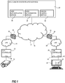
- a system may include a video camera 10 being connected to a communication controller 12 arranged at the video camera 10.
- the video camera may be any network connected video camera, e.g. a surveillance camera, a monitoring camera, a camera arranged in a door station for capturing images of a person requesting access to a closed of area, etc.
- the communication controller 12 may be a device external to the video camera 10, a device built in to the video camera 10, or software code running in an external device 12 or running internally in the camera 10. Communication to and from the video camera 10 passes through the communication controller 12.
- the video camera 10 is being connected to a local communication network 14, i.e. a Local Area Network 14 (LAN), via the communication controller 12.
- the LAN 14 is then connected to a larger communication network 16, i.e. a Wide Area Network 16 (WAN), via a Network Address Translator 18 (NAT) and/or a Firewall 20.
- WAN 16 is part of the Internet 17.
- the system includes a client 22 running a camera management software 24, e.g. a Video Management System.
- the client 22 is connected to a communication controller 26 arranged at the client 22.
- the communication controller 26 may be a device external to the client 22, a device built in to the client 22, or software code running in an external device 26 or running internally in the client 22. Communication to and from the client 22 passes through the communication controller 26.
- the client 22 is being connected to a local communication network 28, i.e. a Local Area Network 28 (LAN), via the communication controller 26.
- the LAN 28 is then connected to the WAN 16 via a NAT 30 and/or a Firewall 32.
- the WAN connected to the LAN 28 including the communication controller 26 at the client 22 may be the same WAN 16 as the one connected to the LAN 14 including the communication controller 12 at the video camera 10 or it could be a totally different WAN. However, independent of whether the WAN is the same or not the two LANs 14, 28, are connected to the same Internet 17.
- video camera system related services 34 Connected to the Internet 17 are at least a couple of video camera system related services 34.
- These video camera system related services 34 includes a user authentication service 36, a user authorization service 38, and a camera control service 40.
- the video camera system related services 34 may be implemented as cloud services.
- a cloud services is a service made available to users on demand via the Internet from a server of a cloud computing provider, e.g. Amazon.
- the video camera system related services 34 may also be implemented on servers dedicated for the video camera system related services, e.g. servers of a surveillance company, servers of the occupants of the premises of which the video is captured, servers of a video camera system installing company, etc.
- the user authentication service 36 is arranged to authenticate users or operators accessing the system including the camera in order to confirm that they really are who they say they are.
- the user authorization service 38 is then arranged to authorize use of specified operations, access to specified devices and/or functions, etc., which operations, devices, and functions are accessible via the Internet.
- the camera control service 40 is arranged to provide access to video cameras registered at the camera control service 40. The access provided is related to configuration of cameras, setting specific parameters of the camera, requesting pan, tilt, or zoom changes for the camera, and streaming of video for viewing or recording.
- the camera control service 40 is also arranged to log changes to configuration and/or parameters of each camera registered, and to instruct the cameras to perform such changes. Hence, the camera control service 40 is enabled to send instructions and data to the registered cameras and receive instructions from authorized users or operators and their client.
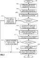
- a process S100 includes connecting the client 22 running the camera management software 24 to the network 28,16 via a logical port 42, on the communication controller 26, S102.
- This connection may be automatically created when the client is physically connecting to the communication controller 26 and is checking for network connections.
- This logical port 42 is configured for managing communication between general functions of the video camera system related service 34 and the client 22 running the camera management software 24.
- the client 22 Upon connection of the camera management client 22 to the management port 42 on the communication controller 26 the client 22 will be connected to the user authentication service 36 via this management port 42, S104.
- the authentication service 36 then request the client 22 to identify itself, e.g. the user of the client may key in a user identity and some kind of password, S106.
- the management port 42 in the communication controller 26 and a status of the connection between the client 22 and the video camera system related services 34 is set to being authenticated, S108. It may also be seen as the management port 42 of the communication controller 26 is authenticated and is allowed to connect to the video camera system related services 34.
- An operator or user of the client 22 is then requesting access to the networked video camera 10 by sending a request for camera access to the video camera system related services 34 and in particular to the authorization service 38, S110.
- the authorization service 38 check if the authenticated connection is allowed to access the video camera 10, S112. If the authenticated connection is not authorized to access the video camera 10, the authorization service 38 return corresponding indication to the client 22 and the client 22 is denied access to the video camera 10, S114. If the authenticated connection is allowed to access the video camera 10 a logic port 44, hereinafter referred to as the camera access port 44, configured to provide access to the video camera 10 and its functionality is set up in the communication controller 26, S118.
- the camera access port 44 in the communication controller 26 may be set up as representing the IP-address of the video camera 10.
- a camera access port 44 is configured for each video camera the client has been allowed to access.
- Each camera access port is unique for the camera it is related to.
- an IP-address of the camera access port 44 is presented to the client 22 as being the address of the camera for which access is requested.
- the client will use this address for communicating with the camera.
- the communication with the camera may then be performed using a protocol on top of the IP protocol, e.g. HTTP.
- the camera access port 44 is set up a process of setting up a direct connection, e.g. a peer-to-peer connection, between the camera access port 44 and a camera control port 46 of the communication controller 12 at the camera 10 is started in the background, S120.
- a peer-to-peer connection is to be interpreted as a direct connection between two specific devices, wherein the connection is direct in the aspect of the communication not being processed and passed on by an intermediate server of some kind.
- Messages sent over the connection may be switched and routed via a plurality of nodes of a network, without the payload of the message being processed by any other devices than the two devices connected by the peer-to-peer connection.
- the peer-to-peer connection is established between the two communication controllers 12 and 26, and more specific between the camera access port 44 and the camera control port 46.
- the setting up of the peer-to-peer tunnel may include an operation generally referred to as "hole punching".
- the "hole punching" operation is a technique commonly used for establishing a direct connection between two networked devices across, for example, fire walls and/or Network Address Translators (NAT) and processes to establish such direct connection is well known by the person skilled in the art.
- NAT Network Address Translators
- the "hole punching" operation may thus be arranged to set up the peer-to-peer connection between the communication controller at the camera and the communication controller at the client running the video manager.
- the peer-to-peer connection to be established between the camera access port 44 and the camera control port 46 may be any kind of setup acting as a communication tunnel for communications between the camera 10 and the client 22. This operation of setting up the direct connection, i.e. the peer-to-peer connection, between the camera access port 44 and the camera control port 46 is performed independently of other camera operations and requests.
- Such operation of setting up the peer-to-peer connection may be started by the camera control service 40 in response to the camera control service receiving an indication that the peer-to-peer connection is down.
- Each of the camera access port 44 and the camera control port 46 is informed when the peer-to-peer connection is available.
- the management port 42 and the camera access port 44 of the communication controller 26 are logical ports in the communication protocols running on the communication controller.
- a port is an address that identifies a network-based application on a computer, in this case on the communication controller 26.
- the management port 42 is implemented as an IP-address representing the port and an HTTP API for transport of instructions, requests, and messages.
- the camera access port 44 is also implemented as an IP-address representing the port and an HTTP API for carrying through instructions, requests, and messages.
- the camera access port 44 of the communication controller 26 at the client 22 is configured to handle all instruction messages and requests for video that is addressed to the video camera 10.
- the camera access port 44 is arranged to send all messages and requests addressed to the video camera 10 to the camera control service 40. Accordingly, instruction messages addressed to the camera 10 and sent from the client is sent to the camera access port 44 and then passed on to the camera control service 40. Further, the camera access port 44 is arranged to send the traffic addressed to the camera 10 to a corresponding camera control service 40 for logging and forwarding to the camera 10. However, when the traffic relates to a video stream or a video transmission and a peer-to-peer connection has been established between the communication controller 26 at the client 22 and the communication controller 12 at the camera 10, the traffic related to the video is sent on the peer-to-peer connection instead of being sent to the camera control service 40.
- the decision whether the data is being sent over the peer-to-peer connection or via the camera control service 40 in the video camera system related services 34 may be made for each packet in a stream or the decision may be made on a level corresponding to a communication session, i.e. the video stream, an instruction transmission and its related response, etc.
- the setup of the peer-to-peer connection will be discussed below.
- a video camera 10 in the network 14, when set up, is also set up with a communication controller 12.
- the camera control port 46 in the communication controller 12 is set up and arranged to communicate with the camera control service 40 included in the video camera system related services 34.
- the camera control port 46 of the communication controller 12 at the camera 10 is set up during a configuration phase when the camera 10 and the communication controller 12 at the camera 10 is connected to the video camera system related services 34.
- the camera control port 46 may be implemented, as described above in connection with the camera access port 44, as an IP-address representing the port and an HTTP API for transport of instructions, requests, and messages.
- the camera control port 46 may be given set up with a specific IP-address, for addressing by the camera and the services accessing the camera, and an HTTP API for carrying through instructions, requests, and messages to and from the camera. Instruction messages from the camera control service 40 and confirmation messages from the video camera 10 are thus communicated through the camera control port 46.
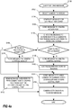
- the process of the client 22 communicating with the camera 10 may be described as follows, see Figs 1 and 4a .
- the following description is based on a system in which the camera 10, the communication controller 12, and the camera control port 46, already are set up and ready to communicate with the camera control service 40 or the video camera system related services 34.
- the client 22 is enabled to send instruction messages, also including requests for video, to the video camera 10 via the API of the camera access port 44.
- a process, S150 of sending a message, e.g.
- an instruction message, a control message, a setup message, a configuration message, a pan instruction, a tilt instruction, a zoom instruction, a video request, etc., from the client 22 to the video camera 10 is depicted.
- the camera 10 that the operator or user want to access for control or video request is selected in an interface of the client 22, S152.
- a message for the camera is then generated at the client, S154, e.g. based on inputs from an operator or a user and sent to the camera access port 44 of the communication controller 26 at the client 22, S156.
- the message is checked, and it is determined if the message is a message that is a candidate for being sent via a peer-to-peer connection or not, S158.
- the type of messages that are candidates for being sent via the peer-to-peer connection may be time critical instruction messages, e.g. pan, tilt, or zoom instructions, that may suffer in performance if extensive latency is introduced.
- Other types of messages benefitting from the peer-to-peer connection are messages including video data or other data requiring a lot of bandwidth. However, such video messages are rarely sent from the client 22 to the camera 10.
- the message is sent to the camera control service 40, S160, where the value, operation, and/or function referred to in the message is logged, S162. Then the message is transmitted to the camera 10 via the communication controller 12 and the camera control port 46, S164. The message is then received at the camera and the value, operation, and/or function, described in the message is set, updated, activated, or executed, S166.
- the camera access port 44 checks if there is an established peer-to-peer connection between the camera access port 44 and the camera control port 46, representing the requested camera 10, S168. If no such peer-to-peer connection is established, the message is sent to the camera control service 40, S170. Then the message is sent to the camera 10 via the communication controller 12 and the camera control port 46, S164, and the camera acts on the value, operation, and/or function, described in the message, S166, in the same way as for a message not being a peer-to-peer communication candidate.
- the communication in this latter case goes back to the process used for communications not being relevant for peer-to-peer communication because a peer-to-peer connection between the two parties is not established yet or have been temporarily lost. Hence, the messages will arrive at the camera even if the preferred communication channel is not present.
- the message is a candidate for being sent via a peer-to-peer connection and a peer-to-peer connection is established, S168, the message is sent over the peer-to-peer connection from the communication controller 26 and the camera access port 44 to the communication controller 12 and the camera control port 46 and then passed on to the camera, S172. Then the camera acts on the data received in the message, S166.
- the above described process allows the system to relay messages sensitive for network latencies or messages representing a large data payload, e.g. video, via a direct connection without taking the detour via a video camera related service system 34 on the Internet.
- a detour via such a service system 34 would likely add latency to any communication and if there is a cost related to data transfers going through such a service system 34 a non-trivial added cost would be related to transfers of large amounts of data, e.g. video.
- many advantages of a service system may still be experienced due to the insightful separation of different types of messages into messages passing through the service system 34 and messages advantageously sent over a direct connection, i.e. peer-to-peer connection.
- the system enables messages that preferably would be sent via the direct connection to be sent via the service system in situations where a direct connection has not been established yet or where a direct connection has failed.
- This failover procedure makes the system according to embodiments of the invention robust and less prone to data loss due to failure of one connection.
- Fig 4b depicting a process for the camera 10 to send messages to the client 22.
- the camera receives a request for data, for set up, for configuration, for a specific operation, etc., S202.
- the camera 10 then generates a message in response to the request, S204, and sends the message to the camera control port 46 in the communication controller 12, S206.
- the message is checked in order to find out if it is a message of a type that is a candidate for transmission over a peer-to-peer connection, S208, examples of types of messages being candidates or not has been previously presented in this description.
- the message is sent on to the camera control service 40, S210, where content, e.g. a value, a parameter, an acknowledgement, etc., of the message is logged, S212.
- the message is then forwarded to the client 22 via the communication controller 26 and the camera access port 44, S214.
- the client 22 the message is processed, and the data is handled in accordance with the type of and the actual pay load of the message received, S216.
- the control port transmits the message via two different paths depending on whether there is an established peer-to-peer connection to the receiving client 22 or not, S218. If no established peer-to-peer connection is present then the message is send to the camera control service 40, S220, and then the camera control service sends the message to the client 22 via the communication controller 26 and the camera access port 44, S214. Then the client 22 processes the message, and the data is handled in accordance with the type of and the actual pay load of the message received, S216.
- the message is sent over the peer-to-peer connection to the client 22 via the communication controller 26 and the camera access port 44, S222. Then the client 22 processes the message, and the data is handled in accordance with the type of and the actual pay load of the message received, S216.
- FIG 5 depicting a communication diagram over an instruction message being sent from the client to the camera.
- an instruction message 232 generated by the client 22 and intended for the camera 10 is sent to the camera access port 44, where it is determined that it is not an instruction message being a candidate for a peer-to-peer connection.
- Such an instruction message may include instructions for changing the settings of a video camera. The setting that is changed may be, for example, frame rate settings, aperture size, gain, etc.
- the camera access port 44 in the communication controller 26 sends the message 234 to the camera control service 40, where data from the instruction message is logged.
- the instruction message 236 is then passed on to the camera control port 46 in the communication controller 12, which in turn sends the instruction message 238 to the camera 10.
- the camera control service will enable easy access to a camera from various clients at various locations.
- the video camera system related services 34 manage authentication and authorization procedures for each camera in a system of cameras and logs the settings of the cameras.
- a video request may be considered a peer-to-peer candidate in some embodiments and in other embodiments such a request is not considered a peer-to-peer candidate.
- One example of a case when you want the video request to be a peer-to-peer candidate is if latency may be an issue.
- the communication in Fig. 6 starts with the client 22 sending the video request 252 to the camera access port 44.
- the camera access port determines if the message, in this case the video request, is of a type that is considered a peer-to-peer candidate.
- the camera access port determines, in some embodiments, that the video request is considered a peer-to-peer candidate and sends it 254 over the established peer-to-peer connection to the camera control port 46.
- the video request is not considered a peer-to-peer candidate and the video request 255, 256, via the camera control service 40 to the camera control port 46.
- the camera control port 46 will pass the video request 257 to the camera 10.
- the camera will process the video request and respond by addressing requested video data to the client.
- the video data 258 is then sent to the camera control port 46.
- the camera control port 46 then identifies the data in the message sent from the camera as video data and send the video data 260 via the peer-to-peer connection to the camera access port 44, as video data is considered a peer-to-peer candidate.
- the camera access port then passes the video data 264 on to the client.
- the video requested by the client either includes too much information for a single message or the request is of live video data which includes data not captured at the time of the request and therefore if for no other reason has to be sent in a plurality of messages. Therefore, the Fig. 6 depicts yet another video data message 270 being sent from the camera to the camera control port 26 which video data message 272 then is passed on to the camera access port 44 and then 274 to the client.
- the number of consecutive video data messages sent depends on how much video data that is to be sent and how much data each video data message may carry.
- the amount of video data to be sent may also be influenced by for how long the camera 10 is to deliver video data, e.g. in a live video situation.
- the camera access port 44 In the camera access port 44, assuming the camera access port 44 being of the embodiment in which the video request is considered a peer-to-peer candidate, the camera access port 44 detects that there is no peer-to-peer connection to the requested camera 10 and therefore sends the video request 306 to the camera control service 40. The camera control service then passes the video request 308 on to the camera control port 46 which in turn sends the video request 310 to the camera 10.
- the camera 10 In response to the video request the camera 10 generates and sends a video message 312 to the camera control port 46. Due to the fact that there is no peer-to-peer connection the message including video data cannot be sent via a peer-to-peer connection.
- the camera control port 46 is aware of this and sends the video data message 314 to the camera control service 40.
- the camera control service 40 passes the video data 316 on to the communication controller 26 and its camera access port 44. From the camera access port 44 the video data 318 is then sent to the client 22, where it is processed and possibly displayed.
- the communication for consecutive video data messages will be the same as the one described referring to the video data 312, 314, 316, 318, unless a peer-to-peer connection is established.
- Reference 320 indicates the re-establishment, or an establishment, of a peer-to-peer connection and the video data 322 sent from the camera after the re-establishment of the peer-to-peer connection will then be sent to the camera control port 46 as before, but then the camera control port 46 will recognise that the peer-to-peer connection is established and send the video data 324 over the peer-to-peer connection to the camera access port 44. Then the video data 326 is sent from the camera access port 44 to the client for processing. Video data transmitted after the re-establishment of the peer-to-peer connection will be sent in accordance with the video data messages 322, 324, and 326, until the peer-to-peer connection is lost again or there is no more data to send.
- Fig. 8 a more communication-focused picture of the connections between the devices of the system according to some embodiments is depicted.
- the system includes the camera 10, the communication controller 12, the camera control port 46, the client 22, the communication controller 26, the camera access port 44, and the video camera system related services 34.
- the video camera system related services 34 is presented inside a cloud symbol indicating that these services 34 may be implemented as cloud services or on servers dedicated for the video camera system related services, which both are described in connection with Fig. 1 .
- Communication paths 402 and 404 between respective communication controller and the video camera system related services 34 are established during setup of each communication controller and allow the system to provide extended services related to video camera systems in addition to the standard services of a video camera system.
- a peer-to-peer connection 406 is established when possible from the time a client 22 requests access to a camera 10.
- the peer-to-peer connection 406 is a direct connection between the two communication controllers or the camera 10 and the client 22, respectively.
- the setup of the peer-to-peer connection 406 may be realise by so called "hole punching" as previously described. The process of hole punching may start as soon as the client 22 request access to the camera 10.
- all communication will be relayed via the video camera system related services 34. Accordingly, the communication controllers 12, 26 will act as intelligent relays directing the communication to a desired and in many cases an optimal path between a client and a camera for the particular communication detected in the message to be transferred.
- An advantage of implementing the video camera system related services as cloud services or on servers dedicated for the video camera system related services may be that the cloud services or servers have greater processing power than a single client. Moreover, security functions, e.g. authentication and authorisation procedures may be shared in the system. Further, the access to the system of cameras will be facilitated. However, this video camera system related services 34 will introduce extra processing of data traffic sent between the client 22 and the camera 10 and vice versa. This extra processing will result in latencies which may lower the quality of some operations and even make some operations very difficult to control, e.g. pan, tilt, zoom. Moreover, the cloud services or the dedicated server implementations may be related to a cost for data traffic received and sent between camera and video camera system related services and between client and video camera system related services. Motion video requires a lot of data and would thereby risk being quite expensive to send via the video camera system related services. In these and other not mentioned cases it is advantageous to send the messages via a direct connection than via a service function on the network.
- a camera access port is configured in the communication controller at the client for each camera and each camera access port is arranged to communicate with a camera control port of the corresponding video camera in communication controllers at the video cameras.
Landscapes
- Engineering & Computer Science (AREA)
- Signal Processing (AREA)
- Multimedia (AREA)
- Computer Networks & Wireless Communication (AREA)
- Physics & Mathematics (AREA)
- General Physics & Mathematics (AREA)
- Two-Way Televisions, Distribution Of Moving Picture Or The Like (AREA)
- Closed-Circuit Television Systems (AREA)
- Studio Devices (AREA)
- Control And Safety Of Cranes (AREA)
Claims (9)
- Procédé de commande à distance d'une caméra vidéo en réseau (10) depuis un client (22) par un réseau à zone étendue WAN (16), ce procédé comprenant :l'envoi d'un message d'instruction, destiné à la caméra vidéo (10), depuis le client (22) à un contrôleur de communication (26) disposé au niveau du client (22) ;la détermination, au niveau du contrôleur de communication (26) disposé au niveau du client (22), si le message d'instruction est candidat pour être envoyé à la caméra vidéo (10) via une connexion de pair à pair de caméra à client (406) ou pas, la connexion de pair à pair de caméra à client (406) étant une connexion directe par le WAN (16) entre le contrôleur de communication (26) disposé au niveau du client (22) et un contrôleur de communication (12) disposé au niveau de la caméra vidéo (10), les messages d'instruction n'étant pas candidats pour être envoyés par la connexion de pair à pair de caméra à client (406) incluant au moins des types de données du groupe des : réglages de vitesse de cadre, réglages de taille d'ouverture, et réglages de gain, et les messages d'instruction étant candidats pour être envoyés par la connexion de pair à pair de caméra à client (406) incluant au moins un des types de données du groupe suivant : requête de données vidéo, requête de données d'image, réglages d'échelle, réglages d'inclinaison et réglages de zoom ;en réaction au fait que le message d'instruction est déterminé comme n'étant pas candidat pour être envoyé à la caméra vidéo (10) via la connexion de pair à pair de caméra à client (406), le procédé comprenant en outre :- l'envoi du message d'instruction depuis le contrôleur de communication (26) disposé au niveau du client (22) par le WAN (16) à un service de commande de caméra (40) ;- l'enregistrement au niveau du service de commande de caméra (40) d'au moins une partie du message d'instruction ; et- l'envoi du message d'instruction reçu au niveau du service de commande de caméra (40) depuis le service de commande de caméra (40) à la caméra vidéo (10) via le WAN (16) ;en réaction au fait que le message d'instruction est déterminé comme étant candidat pour être envoyé à la caméra vidéo (10) via la connexion de pair à pair de caméra à client (406), le procédé comprenant en outre :- l'envoi du message d'instruction depuis le contrôleur de communication (26) disposé au niveau du client (22) au contrôleur de communication (12) disposé au niveau de la caméra vidéo (10) via la connexion de pair à pair de caméra à client (406),- l'envoi du message d'instruction reçu par le contrôleur de communication (12) au niveau de la caméra vidéo (10) depuis le contrôleur de communication (12) au niveau de la caméra vidéo (10) à la caméra vidéo (10) ;la réception au niveau de la caméra vidéo (10) du message d'instruction via un élément parmi le service de commande (40) ou la connexion de pair à pair de caméra à client (406) ; etl'exécution au niveau de la caméra vidéo (10) de l'instruction contenue dans le message d'instruction.
- Procédé selon la revendication 1, dans lequel le contrôleur de communication (26) disposé au niveau du client (22) est connecté directement au client (22) et connecte le client (22) au WAN (16).
- Procédé selon l'une quelconque des revendications 1 à 2, dans lequel le contrôleur de communication (12) disposé au niveau de la caméra vidéo (10) est connecté directement à la caméra vidéo (10) et connecte la caméra vidéo (10) au WAN (16).
- Procédé selon l'une quelconque des revendications 1 à 3, comprenant en outre :l'envoi d'une requête d'accès demandant l'accès à la caméra vidéo (10), la requête d'accès étant envoyée par le client (22) à un service d'autorisation d'utilisateur (38) via le WAN (16) ;la vérification au niveau du service d'autorisation d'utilisateur (38) si le client (22) est autorisé à accéder à la caméra vidéo demandée (10) ;l'envoi, en réaction au fait que l'accès de la caméra vidéo (10) est autorisé, d'un message d'instruction par le service d'autorisation d'utilisateur (38) au contrôleur de communication (26) disposé au niveau du client (22) en donnant à ce contrôleur de communication (26) l'instruction d'établir un port l'accès à la caméra (44) pour une communication entre le client (22) et la caméra vidéo (10), etl'initiation, en réaction au fait que la caméra vidéo (10) est autorisé, de l'établissement de la connexion de pair à pair de client à caméra (406) entre le port l'accès à la caméra (44) et un port de commande de caméra (46) dans le contrôleur de communication (12) disposé au niveau de la caméra vidéo (10).
- Procédé selon la revendication 4, dans lequel l'envoi d'un message d'instruction destiné à la caméra vidéo (10) depuis le client (22) inclut le fait que le client (22) adresse le message d'instruction destiné à la caméra vidéo (10) à une adresse IP identifiant le port l'accès à la caméra (44).
- Procédé selon l'une quelconque des revendications 1 à 5, comprenant en outre :
en réaction au fait que le message d'instruction reçu au niveau de la caméra vidéo (10) est une requête vidéo, la réalisation des étapes suivantes :envoi de messages de données vidéo depuis la caméra vidéo (10) au contrôleur de communication (12) disposé au niveau de la caméra vidéo (10) ;détermination, au niveau du contrôleur de communication (12) disposé au niveau de la caméra vidéo (10), que chaque message de données vidéo est candidat pour être envoyé au client (22) via la connexion de pair à pair de client à caméra (406),envoi de chaque message de données vidéo reçu au niveau du contrôleur de communication disposé au niveau de la caméra vidéo (10) via la connexion de pair à pair de client à caméra (406) au contrôleur de communication (26) disposé au niveau du client (22),envoi de chaque message de données vidéo reçu au niveau du contrôleur de communication (26) disposé au niveau du client (22) au client pour traitement ultérieur. - Procédé selon l'une quelconque des revendications 1 à 6, dans lequel le service de commande de caméra (40) est un processus fonctionnant sur un serveur accessible via le WAN (16).
- Système de contrôle vidéo en réseau comprenant :une caméra vidéo (10) connectée à un réseau à zone étendue WAN (16) via un contrôleur de communication (12) disposé au niveau de la caméra vidéo (10) ;un client (22) conçu pour contrôler les données vidéo provenant de caméras vidéo auxquelles on a accès via le WAN (16), le client (22) étant connecté au WAN (16) via un contrôleur de communication (26) disposé au niveau du client (22) ;un service de commande caméra (40) conçu pour enregistrer des instructions envoyées à la caméra, le service de commande de caméra (40) étant mis en oeuvre dans un serveur connecté au WAN (16), etle contrôleur de communication (26) disposé au niveau du client (22) étant conçu pour :déterminer si un message d'instruction envoyé par le client (22) et adressé à la caméra vidéo (10) est candidat pour être envoyé à la caméra via une connexion de pair à pair de caméra à client (406) ou pas, la connexion de pair à pair de caméra à client (406) ou pas, la connexion de pair à pair de caméra à client (406) étant une connexion directe par le WLAN (16) entre le contrôleur de communication (26) disposé au niveau du client (22) et le contrôleur de communication (12) disposé au niveau de la caméra vidéo (10), les messages d'instruction n'étant pas candidats pour être envoyés par la connexion de pair à pair de caméra à client (406) incluant au moins un des types de données du groupe des : réglages de vitesse de cadre, réglages de taille d'ouverture, et réglages de gain, et les messages d'instruction étant candidats pour être envoyés par la connexion de pair à pair de caméra à client (406) incluant au moins un des types de données suivant : requête de données vidéo, requête de données d'image, réglages d'échelle, réglages d'inclinaison et réglages de zoom ;envoyer chaque message d'instruction déterminé comme n'étant pas candidat pour être envoyé via la connexion de pair à pair de caméra à client (406) au service de commande de caméra (40) ; etenvoyer chaque message d'instruction déterminée comme étant candidat pour être envoyé via la connexion de pair à pair de caméra à client (406) la caméra vidéo (10) via la connexion de pair à pair de caméra à client (406).
- Système de contrôle vidéo en réseau selon la revendication 8, dans lequel le contrôleur de communication (12) disposé au niveau de la caméra vidéo (10) est conçu pour déterminer si un message envoyé depuis la caméra vidéo (10) et adressé au client (22) est candidat pour être envoyé au client (22) via la connexion de pair à pair de client à caméra (406) ou pas, et conçu pour envoyer chaque message déterminé comme n'étant pas candidat à être envoyé via la connexion de pair à pair de client à caméra (406) au service de commande de caméra (40), et conçu pour envoyer chaque message déterminé comme étant candidat à être envoyé via la connexion de pair à pair de client à caméra (406) au client (22) via la connexion de pair à pair de client à caméra (406).
Priority Applications (6)
| Application Number | Priority Date | Filing Date | Title |
|---|---|---|---|
| EP18213342.1A EP3672232B1 (fr) | 2018-12-18 | 2018-12-18 | Procédé et système de commande de caméras |
| KR1020190134541A KR102769044B1 (ko) | 2018-12-18 | 2019-10-28 | 카메라를 제어하기 위한 방법 및 시스템 |
| JP2019209246A JP7398251B2 (ja) | 2018-12-18 | 2019-11-20 | ビデオカメラを遠隔制御する方法およびビデオ監視システム |
| CN201911281058.7A CN111343378B (zh) | 2018-12-18 | 2019-12-13 | 用于控制摄像机的方法和系统 |
| US16/715,659 US10878678B2 (en) | 2018-12-18 | 2019-12-16 | Method and system for controlling cameras |
| TW108146399A TWI803723B (zh) | 2018-12-18 | 2019-12-18 | 用於控制攝像機的方法和系統 |
Applications Claiming Priority (1)
| Application Number | Priority Date | Filing Date | Title |
|---|---|---|---|
| EP18213342.1A EP3672232B1 (fr) | 2018-12-18 | 2018-12-18 | Procédé et système de commande de caméras |
Publications (2)
| Publication Number | Publication Date |
|---|---|
| EP3672232A1 EP3672232A1 (fr) | 2020-06-24 |
| EP3672232B1 true EP3672232B1 (fr) | 2020-11-04 |
Family
ID=64959138
Family Applications (1)
| Application Number | Title | Priority Date | Filing Date |
|---|---|---|---|
| EP18213342.1A Active EP3672232B1 (fr) | 2018-12-18 | 2018-12-18 | Procédé et système de commande de caméras |
Country Status (6)
| Country | Link |
|---|---|
| US (1) | US10878678B2 (fr) |
| EP (1) | EP3672232B1 (fr) |
| JP (1) | JP7398251B2 (fr) |
| KR (1) | KR102769044B1 (fr) |
| CN (1) | CN111343378B (fr) |
| TW (1) | TWI803723B (fr) |
Cited By (1)
| Publication number | Priority date | Publication date | Assignee | Title |
|---|---|---|---|---|
| US20240007523A1 (en) * | 2022-06-29 | 2024-01-04 | Western Digital Technologies, Inc. | Video Surveillance Systems Using Out of Band Key Exchange |
Families Citing this family (5)
| Publication number | Priority date | Publication date | Assignee | Title |
|---|---|---|---|---|
| CN113014885B (zh) * | 2021-03-15 | 2023-07-11 | 通号通信信息集团有限公司 | 一种铁路视频资源互联汇聚系统及方法 |
| US11954989B2 (en) * | 2021-04-15 | 2024-04-09 | Motorola Solutions, Inc. | Image recognition based configuration/authorization method for video security systems |
| CN113556467A (zh) * | 2021-07-21 | 2021-10-26 | 中国电信股份有限公司 | 网络摄像机的控制方法、控制系统、存储介质、电子设备 |
| JP7290373B1 (ja) | 2022-05-10 | 2023-06-13 | 株式会社ピーゼットピー | 情報管理システム |
| DE112024002790T5 (de) * | 2023-06-30 | 2026-04-09 | Soracom, Inc. | System und Verfahren zur Erleichterung einer cloudbasierten Videostreamverarbeitung |
Family Cites Families (13)
| Publication number | Priority date | Publication date | Assignee | Title |
|---|---|---|---|---|
| JP2003283701A (ja) | 2002-03-25 | 2003-10-03 | Hitachi Advanced Digital Inc | ネットワークカメラ装置およびこれを用いた情報通信システム |
| WO2008127194A1 (fr) * | 2007-04-12 | 2008-10-23 | Yu Zhou | Système et procédé de surveillance de caméra de réseau et de partage de données |
| US20110123972A1 (en) * | 2008-08-04 | 2011-05-26 | Lior Friedman | System for automatic production of lectures and presentations for live or on-demand publishing and sharing |
| US20100217814A1 (en) * | 2009-02-18 | 2010-08-26 | Bert Strueber | Apparatus and method for enabling network-compatible cameras to operate in instant messaging networks |
| ITMI20091600A1 (it) * | 2009-09-18 | 2011-03-19 | March Networks Corp | Tolleranza ai guasti in un sistema di video sorveglianza |
| CN102209232A (zh) * | 2010-04-09 | 2011-10-05 | 佛山市智邦电子科技有限公司 | 一种远程音视频监控系统及其方法 |
| CN101938485B (zh) * | 2010-09-10 | 2014-05-14 | 上海复控华龙微系统技术有限公司 | 基于双向安全认证的点对点协议的IP Camera服务实现方法 |
| CN102014122B (zh) * | 2010-09-10 | 2015-04-22 | 上海复控华龙微系统技术有限公司 | 基于双向安全认证的点对点协议的IP Camera服务系统 |
| KR101758681B1 (ko) | 2012-03-27 | 2017-07-14 | 한화테크윈 주식회사 | 통신 시스템 및 통신 시스템에서의 데이터 송수신 방법 |
| JP6039415B2 (ja) | 2012-12-28 | 2016-12-07 | キヤノン株式会社 | 無線通信装置、その制御方法、プログラム |
| WO2015013315A1 (fr) * | 2013-07-22 | 2015-01-29 | Intellivision Technologies Corp. | Système et procédé pour services de nuage vidéo évolutif |
| CA2941431C (fr) | 2014-03-28 | 2018-01-09 | Aetonix Systems | Simple plate-forme de communication video |
| TWI552000B (zh) | 2015-03-16 | 2016-10-01 | 鋐寶科技股份有限公司 | 安裝方法及網路監視系統 |
-
2018
- 2018-12-18 EP EP18213342.1A patent/EP3672232B1/fr active Active
-
2019
- 2019-10-28 KR KR1020190134541A patent/KR102769044B1/ko active Active
- 2019-11-20 JP JP2019209246A patent/JP7398251B2/ja active Active
- 2019-12-13 CN CN201911281058.7A patent/CN111343378B/zh active Active
- 2019-12-16 US US16/715,659 patent/US10878678B2/en active Active
- 2019-12-18 TW TW108146399A patent/TWI803723B/zh active
Non-Patent Citations (1)
| Title |
|---|
| None * |
Cited By (2)
| Publication number | Priority date | Publication date | Assignee | Title |
|---|---|---|---|---|
| US20240007523A1 (en) * | 2022-06-29 | 2024-01-04 | Western Digital Technologies, Inc. | Video Surveillance Systems Using Out of Band Key Exchange |
| US12177293B2 (en) * | 2022-06-29 | 2024-12-24 | SanDisk Technologies, Inc. | Video surveillance systems using out of band key exchange |
Also Published As
| Publication number | Publication date |
|---|---|
| US20200193788A1 (en) | 2020-06-18 |
| TWI803723B (zh) | 2023-06-01 |
| JP7398251B2 (ja) | 2023-12-14 |
| EP3672232A1 (fr) | 2020-06-24 |
| CN111343378B (zh) | 2022-07-22 |
| US10878678B2 (en) | 2020-12-29 |
| JP2020113970A (ja) | 2020-07-27 |
| CN111343378A (zh) | 2020-06-26 |
| KR102769044B1 (ko) | 2025-02-14 |
| TW202038602A (zh) | 2020-10-16 |
| KR20200075733A (ko) | 2020-06-26 |
Similar Documents
| Publication | Publication Date | Title |
|---|---|---|
| EP3672232B1 (fr) | Procédé et système de commande de caméras | |
| EP3834393B1 (fr) | Systèmes et procédés pour la communication de réseau de cluster de serveurs sur l'internet public | |
| EP2229762B1 (fr) | Serveur | |
| EP1891784B1 (fr) | Systeme et procede de communication sur reseau securise | |
| EP2074791B1 (fr) | Système de communication | |
| JP6193185B2 (ja) | 通信装置、端末装置およびプログラム | |
| US12273397B2 (en) | Methods and systems for proxy relay implementation for client-server connections over wide area network | |
| CN114390049A (zh) | 一种应用数据获取方法及装置 | |
| KR101881061B1 (ko) | 모드 변경이 가능한 양방향 통신 장치 및 방법 | |
| CN101103608A (zh) | 监视系统与访问监视系统的监视设备的方法 | |
| JP2002368826A (ja) | 中継サーバ及び中継システム | |
| JP6351426B2 (ja) | 作業支援システムおよび作業支援方法 | |
| KR102335670B1 (ko) | 웹소켓을 이용하여 중간 서버를 경유하는 미디어 스트리밍 방법 | |
| GB2461596A (en) | IP network camera and server system | |
| GB2607362A (en) | Private cloud routing server connection mechanism for use in a private communication architecture | |
| US20230112657A1 (en) | System and Method for Tunneling Network Requests to a Device via a Persistent Connection | |
| US12556637B2 (en) | System for establishing communication | |
| US9900373B2 (en) | System for providing a service, such as a communication service | |
| JP5784059B2 (ja) | 通信制御方法、ローカル装置、情報処理端末、通信経路確立支援装置及びプログラム | |
| JP2014200017A (ja) | 中継装置、情報処理方法、及びプログラム | |
| JPWO2020122040A1 (ja) | 情報通信機器用のインターネット接続管理システム及びその方法、情報通信機器にインストールされるインターネット接続管理プログラム | |
| JP2017123593A (ja) | パケットフィルタリング装置、パケットフィルタリング方法およびパケットフィルタリングプログラム | |
| JP2005151295A (ja) | 通信制御方法及び装置 |
Legal Events
| Date | Code | Title | Description |
|---|---|---|---|
| STAA | Information on the status of an ep patent application or granted ep patent |
Free format text: STATUS: EXAMINATION IS IN PROGRESS |
|
| PUAI | Public reference made under article 153(3) epc to a published international application that has entered the european phase |
Free format text: ORIGINAL CODE: 0009012 |
|
| 17P | Request for examination filed |
Effective date: 20190812 |
|
| AK | Designated contracting states |
Kind code of ref document: A1 Designated state(s): AL AT BE BG CH CY CZ DE DK EE ES FI FR GB GR HR HU IE IS IT LI LT LU LV MC MK MT NL NO PL PT RO RS SE SI SK SM TR |
|
| AX | Request for extension of the european patent |
Extension state: BA ME |
|
| GRAP | Despatch of communication of intention to grant a patent |
Free format text: ORIGINAL CODE: EPIDOSNIGR1 |
|
| STAA | Information on the status of an ep patent application or granted ep patent |
Free format text: STATUS: GRANT OF PATENT IS INTENDED |
|
| INTG | Intention to grant announced |
Effective date: 20200804 |
|
| GRAS | Grant fee paid |
Free format text: ORIGINAL CODE: EPIDOSNIGR3 |
|
| GRAA | (expected) grant |
Free format text: ORIGINAL CODE: 0009210 |
|
| STAA | Information on the status of an ep patent application or granted ep patent |
Free format text: STATUS: THE PATENT HAS BEEN GRANTED |
|
| AK | Designated contracting states |
Kind code of ref document: B1 Designated state(s): AL AT BE BG CH CY CZ DE DK EE ES FI FR GB GR HR HU IE IS IT LI LT LU LV MC MK MT NL NO PL PT RO RS SE SI SK SM TR |
|
| REG | Reference to a national code |
Ref country code: GB Ref legal event code: FG4D |
|
| REG | Reference to a national code |
Ref country code: CH Ref legal event code: EP |
|
| REG | Reference to a national code |
Ref country code: AT Ref legal event code: REF Ref document number: 1332333 Country of ref document: AT Kind code of ref document: T Effective date: 20201115 |
|
| REG | Reference to a national code |
Ref country code: DE Ref legal event code: R096 Ref document number: 602018009426 Country of ref document: DE |
|
| REG | Reference to a national code |
Ref country code: SE Ref legal event code: TRGR |
|
| REG | Reference to a national code |
Ref country code: IE Ref legal event code: FG4D |
|
| RAP2 | Party data changed (patent owner data changed or rights of a patent transferred) |
Owner name: AXIS AB |
|
| REG | Reference to a national code |
Ref country code: NL Ref legal event code: MP Effective date: 20201104 |
|
| REG | Reference to a national code |
Ref country code: AT Ref legal event code: MK05 Ref document number: 1332333 Country of ref document: AT Kind code of ref document: T Effective date: 20201104 |
|
| PG25 | Lapsed in a contracting state [announced via postgrant information from national office to epo] |
Ref country code: RS Free format text: LAPSE BECAUSE OF FAILURE TO SUBMIT A TRANSLATION OF THE DESCRIPTION OR TO PAY THE FEE WITHIN THE PRESCRIBED TIME-LIMIT Effective date: 20201104 Ref country code: PT Free format text: LAPSE BECAUSE OF FAILURE TO SUBMIT A TRANSLATION OF THE DESCRIPTION OR TO PAY THE FEE WITHIN THE PRESCRIBED TIME-LIMIT Effective date: 20210304 Ref country code: FI Free format text: LAPSE BECAUSE OF FAILURE TO SUBMIT A TRANSLATION OF THE DESCRIPTION OR TO PAY THE FEE WITHIN THE PRESCRIBED TIME-LIMIT Effective date: 20201104 Ref country code: NO Free format text: LAPSE BECAUSE OF FAILURE TO SUBMIT A TRANSLATION OF THE DESCRIPTION OR TO PAY THE FEE WITHIN THE PRESCRIBED TIME-LIMIT Effective date: 20210204 Ref country code: GR Free format text: LAPSE BECAUSE OF FAILURE TO SUBMIT A TRANSLATION OF THE DESCRIPTION OR TO PAY THE FEE WITHIN THE PRESCRIBED TIME-LIMIT Effective date: 20210205 |
|
| PG25 | Lapsed in a contracting state [announced via postgrant information from national office to epo] |
Ref country code: IS Free format text: LAPSE BECAUSE OF FAILURE TO SUBMIT A TRANSLATION OF THE DESCRIPTION OR TO PAY THE FEE WITHIN THE PRESCRIBED TIME-LIMIT Effective date: 20210304 Ref country code: PL Free format text: LAPSE BECAUSE OF FAILURE TO SUBMIT A TRANSLATION OF THE DESCRIPTION OR TO PAY THE FEE WITHIN THE PRESCRIBED TIME-LIMIT Effective date: 20201104 Ref country code: LV Free format text: LAPSE BECAUSE OF FAILURE TO SUBMIT A TRANSLATION OF THE DESCRIPTION OR TO PAY THE FEE WITHIN THE PRESCRIBED TIME-LIMIT Effective date: 20201104 Ref country code: BG Free format text: LAPSE BECAUSE OF FAILURE TO SUBMIT A TRANSLATION OF THE DESCRIPTION OR TO PAY THE FEE WITHIN THE PRESCRIBED TIME-LIMIT Effective date: 20210204 Ref country code: AT Free format text: LAPSE BECAUSE OF FAILURE TO SUBMIT A TRANSLATION OF THE DESCRIPTION OR TO PAY THE FEE WITHIN THE PRESCRIBED TIME-LIMIT Effective date: 20201104 Ref country code: ES Free format text: LAPSE BECAUSE OF FAILURE TO SUBMIT A TRANSLATION OF THE DESCRIPTION OR TO PAY THE FEE WITHIN THE PRESCRIBED TIME-LIMIT Effective date: 20201104 |
|
| REG | Reference to a national code |
Ref country code: LT Ref legal event code: MG9D |
|
| PG25 | Lapsed in a contracting state [announced via postgrant information from national office to epo] |
Ref country code: HR Free format text: LAPSE BECAUSE OF FAILURE TO SUBMIT A TRANSLATION OF THE DESCRIPTION OR TO PAY THE FEE WITHIN THE PRESCRIBED TIME-LIMIT Effective date: 20201104 |
|
| PG25 | Lapsed in a contracting state [announced via postgrant information from national office to epo] |
Ref country code: LT Free format text: LAPSE BECAUSE OF FAILURE TO SUBMIT A TRANSLATION OF THE DESCRIPTION OR TO PAY THE FEE WITHIN THE PRESCRIBED TIME-LIMIT Effective date: 20201104 Ref country code: RO Free format text: LAPSE BECAUSE OF FAILURE TO SUBMIT A TRANSLATION OF THE DESCRIPTION OR TO PAY THE FEE WITHIN THE PRESCRIBED TIME-LIMIT Effective date: 20201104 Ref country code: EE Free format text: LAPSE BECAUSE OF FAILURE TO SUBMIT A TRANSLATION OF THE DESCRIPTION OR TO PAY THE FEE WITHIN THE PRESCRIBED TIME-LIMIT Effective date: 20201104 Ref country code: CZ Free format text: LAPSE BECAUSE OF FAILURE TO SUBMIT A TRANSLATION OF THE DESCRIPTION OR TO PAY THE FEE WITHIN THE PRESCRIBED TIME-LIMIT Effective date: 20201104 Ref country code: SK Free format text: LAPSE BECAUSE OF FAILURE TO SUBMIT A TRANSLATION OF THE DESCRIPTION OR TO PAY THE FEE WITHIN THE PRESCRIBED TIME-LIMIT Effective date: 20201104 Ref country code: SM Free format text: LAPSE BECAUSE OF FAILURE TO SUBMIT A TRANSLATION OF THE DESCRIPTION OR TO PAY THE FEE WITHIN THE PRESCRIBED TIME-LIMIT Effective date: 20201104 |
|
| REG | Reference to a national code |
Ref country code: DE Ref legal event code: R097 Ref document number: 602018009426 Country of ref document: DE |
|
| PG25 | Lapsed in a contracting state [announced via postgrant information from national office to epo] |
Ref country code: DK Free format text: LAPSE BECAUSE OF FAILURE TO SUBMIT A TRANSLATION OF THE DESCRIPTION OR TO PAY THE FEE WITHIN THE PRESCRIBED TIME-LIMIT Effective date: 20201104 Ref country code: MC Free format text: LAPSE BECAUSE OF FAILURE TO SUBMIT A TRANSLATION OF THE DESCRIPTION OR TO PAY THE FEE WITHIN THE PRESCRIBED TIME-LIMIT Effective date: 20201104 |
|
| REG | Reference to a national code |
Ref country code: BE Ref legal event code: MM Effective date: 20201231 |
|
| PLBE | No opposition filed within time limit |
Free format text: ORIGINAL CODE: 0009261 |
|
| STAA | Information on the status of an ep patent application or granted ep patent |
Free format text: STATUS: NO OPPOSITION FILED WITHIN TIME LIMIT |
|
| 26N | No opposition filed |
Effective date: 20210805 |
|
| PG25 | Lapsed in a contracting state [announced via postgrant information from national office to epo] |
Ref country code: NL Free format text: LAPSE BECAUSE OF FAILURE TO SUBMIT A TRANSLATION OF THE DESCRIPTION OR TO PAY THE FEE WITHIN THE PRESCRIBED TIME-LIMIT Effective date: 20201104 Ref country code: AL Free format text: LAPSE BECAUSE OF FAILURE TO SUBMIT A TRANSLATION OF THE DESCRIPTION OR TO PAY THE FEE WITHIN THE PRESCRIBED TIME-LIMIT Effective date: 20201104 Ref country code: IT Free format text: LAPSE BECAUSE OF FAILURE TO SUBMIT A TRANSLATION OF THE DESCRIPTION OR TO PAY THE FEE WITHIN THE PRESCRIBED TIME-LIMIT Effective date: 20201104 Ref country code: LU Free format text: LAPSE BECAUSE OF NON-PAYMENT OF DUE FEES Effective date: 20201218 Ref country code: IE Free format text: LAPSE BECAUSE OF NON-PAYMENT OF DUE FEES Effective date: 20201218 |
|
| PG25 | Lapsed in a contracting state [announced via postgrant information from national office to epo] |
Ref country code: SI Free format text: LAPSE BECAUSE OF FAILURE TO SUBMIT A TRANSLATION OF THE DESCRIPTION OR TO PAY THE FEE WITHIN THE PRESCRIBED TIME-LIMIT Effective date: 20201104 |
|
| PG25 | Lapsed in a contracting state [announced via postgrant information from national office to epo] |
Ref country code: IS Free format text: LAPSE BECAUSE OF FAILURE TO SUBMIT A TRANSLATION OF THE DESCRIPTION OR TO PAY THE FEE WITHIN THE PRESCRIBED TIME-LIMIT Effective date: 20210304 Ref country code: TR Free format text: LAPSE BECAUSE OF FAILURE TO SUBMIT A TRANSLATION OF THE DESCRIPTION OR TO PAY THE FEE WITHIN THE PRESCRIBED TIME-LIMIT Effective date: 20201104 Ref country code: MT Free format text: LAPSE BECAUSE OF FAILURE TO SUBMIT A TRANSLATION OF THE DESCRIPTION OR TO PAY THE FEE WITHIN THE PRESCRIBED TIME-LIMIT Effective date: 20201104 Ref country code: CY Free format text: LAPSE BECAUSE OF FAILURE TO SUBMIT A TRANSLATION OF THE DESCRIPTION OR TO PAY THE FEE WITHIN THE PRESCRIBED TIME-LIMIT Effective date: 20201104 |
|
| PG25 | Lapsed in a contracting state [announced via postgrant information from national office to epo] |
Ref country code: MK Free format text: LAPSE BECAUSE OF FAILURE TO SUBMIT A TRANSLATION OF THE DESCRIPTION OR TO PAY THE FEE WITHIN THE PRESCRIBED TIME-LIMIT Effective date: 20201104 |
|
| PG25 | Lapsed in a contracting state [announced via postgrant information from national office to epo] |
Ref country code: BE Free format text: LAPSE BECAUSE OF NON-PAYMENT OF DUE FEES Effective date: 20201231 |
|
| REG | Reference to a national code |
Ref country code: CH Ref legal event code: PL |
|
| PG25 | Lapsed in a contracting state [announced via postgrant information from national office to epo] |
Ref country code: LI Free format text: LAPSE BECAUSE OF NON-PAYMENT OF DUE FEES Effective date: 20211231 Ref country code: CH Free format text: LAPSE BECAUSE OF NON-PAYMENT OF DUE FEES Effective date: 20211231 |
|
| P01 | Opt-out of the competence of the unified patent court (upc) registered |
Effective date: 20230505 |
|
| PGFP | Annual fee paid to national office [announced via postgrant information from national office to epo] |
Ref country code: DE Payment date: 20251126 Year of fee payment: 8 |
|
| PGFP | Annual fee paid to national office [announced via postgrant information from national office to epo] |
Ref country code: GB Payment date: 20251120 Year of fee payment: 8 |
|
| PGFP | Annual fee paid to national office [announced via postgrant information from national office to epo] |
Ref country code: FR Payment date: 20251120 Year of fee payment: 8 |
|
| PGFP | Annual fee paid to national office [announced via postgrant information from national office to epo] |
Ref country code: SE Payment date: 20251119 Year of fee payment: 8 |