EP3672275A1 - Procédé et système d'extraction de signal source, et support de stockage - Google Patents
Procédé et système d'extraction de signal source, et support de stockage Download PDFInfo
- Publication number
- EP3672275A1 EP3672275A1 EP17921701.3A EP17921701A EP3672275A1 EP 3672275 A1 EP3672275 A1 EP 3672275A1 EP 17921701 A EP17921701 A EP 17921701A EP 3672275 A1 EP3672275 A1 EP 3672275A1
- Authority
- EP
- European Patent Office
- Prior art keywords
- signal
- signals
- input signals
- unwanted
- input
- Prior art date
- Legal status (The legal status is an assumption and is not a legal conclusion. Google has not performed a legal analysis and makes no representation as to the accuracy of the status listed.)
- Withdrawn
Links
Images



Classifications
-
- H—ELECTRICITY
- H04—ELECTRIC COMMUNICATION TECHNIQUE
- H04R—LOUDSPEAKERS, MICROPHONES, GRAMOPHONE PICK-UPS OR LIKE ACOUSTIC ELECTROMECHANICAL TRANSDUCERS; ELECTRIC HEARING AIDS; PUBLIC ADDRESS SYSTEMS
- H04R3/00—Circuits for transducers
-
- H—ELECTRICITY
- H04—ELECTRIC COMMUNICATION TECHNIQUE
- H04R—LOUDSPEAKERS, MICROPHONES, GRAMOPHONE PICK-UPS OR LIKE ACOUSTIC ELECTROMECHANICAL TRANSDUCERS; ELECTRIC HEARING AIDS; PUBLIC ADDRESS SYSTEMS
- H04R3/00—Circuits for transducers
- H04R3/005—Circuits for transducers for combining the signals of two or more microphones
-
- G—PHYSICS
- G10—MUSICAL INSTRUMENTS; ACOUSTICS
- G10L—SPEECH ANALYSIS TECHNIQUES OR SPEECH SYNTHESIS; SPEECH RECOGNITION; SPEECH OR VOICE PROCESSING TECHNIQUES; SPEECH OR AUDIO CODING OR DECODING
- G10L21/00—Speech or voice signal processing techniques to produce another audible or non-audible signal, e.g. visual or tactile, in order to modify its quality or its intelligibility
- G10L21/02—Speech enhancement, e.g. noise reduction or echo cancellation
- G10L21/0272—Voice signal separating
-
- H—ELECTRICITY
- H04—ELECTRIC COMMUNICATION TECHNIQUE
- H04R—LOUDSPEAKERS, MICROPHONES, GRAMOPHONE PICK-UPS OR LIKE ACOUSTIC ELECTROMECHANICAL TRANSDUCERS; ELECTRIC HEARING AIDS; PUBLIC ADDRESS SYSTEMS
- H04R25/00—Electric hearing aids
- H04R25/40—Arrangements for obtaining a desired directivity characteristic
- H04R25/407—Circuits for combining signals of a plurality of transducers
-
- H—ELECTRICITY
- H04—ELECTRIC COMMUNICATION TECHNIQUE
- H04R—LOUDSPEAKERS, MICROPHONES, GRAMOPHONE PICK-UPS OR LIKE ACOUSTIC ELECTROMECHANICAL TRANSDUCERS; ELECTRIC HEARING AIDS; PUBLIC ADDRESS SYSTEMS
- H04R1/00—Details of transducers, loudspeakers or microphones
- H04R1/20—Arrangements for obtaining desired frequency or directional characteristics
- H04R1/32—Arrangements for obtaining desired frequency or directional characteristics for obtaining desired directional characteristic only
- H04R1/40—Arrangements for obtaining desired frequency or directional characteristics for obtaining desired directional characteristic only by combining a number of identical transducers
- H04R1/406—Arrangements for obtaining desired frequency or directional characteristics for obtaining desired directional characteristic only by combining a number of identical transducers microphones
-
- H—ELECTRICITY
- H04—ELECTRIC COMMUNICATION TECHNIQUE
- H04R—LOUDSPEAKERS, MICROPHONES, GRAMOPHONE PICK-UPS OR LIKE ACOUSTIC ELECTROMECHANICAL TRANSDUCERS; ELECTRIC HEARING AIDS; PUBLIC ADDRESS SYSTEMS
- H04R2225/00—Details of deaf aids covered by H04R25/00, not provided for in any of its subgroups
- H04R2225/43—Signal processing in hearing aids to enhance the speech intelligibility
-
- H—ELECTRICITY
- H04—ELECTRIC COMMUNICATION TECHNIQUE
- H04R—LOUDSPEAKERS, MICROPHONES, GRAMOPHONE PICK-UPS OR LIKE ACOUSTIC ELECTROMECHANICAL TRANSDUCERS; ELECTRIC HEARING AIDS; PUBLIC ADDRESS SYSTEMS
- H04R2430/00—Signal processing covered by H04R, not provided for in its groups
-
- H—ELECTRICITY
- H04—ELECTRIC COMMUNICATION TECHNIQUE
- H04R—LOUDSPEAKERS, MICROPHONES, GRAMOPHONE PICK-UPS OR LIKE ACOUSTIC ELECTROMECHANICAL TRANSDUCERS; ELECTRIC HEARING AIDS; PUBLIC ADDRESS SYSTEMS
- H04R2430/00—Signal processing covered by H04R, not provided for in its groups
- H04R2430/20—Processing of the output signals of the acoustic transducers of an array for obtaining a desired directivity characteristic
- H04R2430/23—Direction finding using a sum-delay beam-former
Definitions
- the disclosure relates to the field of signal processing technology, more particularly to a method, system and storage medium for extracting a target unwanted signal from a mixture of signals.
- the separation technology is mainly to operate the hearing device by selectively adjusting the proportion of the signal, focusing on how to calculate the coefficient matrix more effectively, or using a combination of a directional microphone and an omnidirectional microphone to enhance the clarity of the voice, but the traditional independent component analysis (ICA) algorithm cannot achieve the ideal effect and the removal effect of the interference signal is not ideal. And the accuracy of the ICA algorithm is destroyed.
- ICA independent component analysis
- the disclosure solves the technical problem of incomplete signal separation while simplifying the operations, and achieves the effect of removing interference signals with extremely high precision by means of time-domain synchronization of signals.
- One aspect of the disclosure discloses a method for removing a target unwanted signal from multiple signals, comprising: providing a set of input signals with each of the input signals comprising the wanted and unwanted signals; maximizing and maintaining the independence of the input signals; estimating the coefficients to maximize the independence; synchronizing the set of input signals; separating the set of synchronized input signals into channels with unwanted signal and channels without unwanted signal; and selecting optimal channel without unwanted signal as output signal intelligently.
- a system for removing a target unwanted signal from multiple signal comprising a set of input units for inputting two or more input signals; a processor; and a memory storing computer readable instructions which when executed by the processor, cause the processor to: maximize and maintain the independence of the sets of input signals; extract the coefficients to maximize the independence among the input channels; synchronize the sets of input signals; separate the sets of synchronized input signals into channels with unwanted signal and channels without unwanted signal; and selecting the optimal channel without unwanted signal as output signal intelligently.
- Still another aspect of the disclosure discloses a non-transitory computer storage medium, storing computer-readable instructions which when executed by a processor, cause the processor to perform a method for removing the unwanted signal from multiple signals, the method comprising: providing a set of input signals with each of the input signals comprising the wanted and unwanted signals; maximizing and maintaining the independence of the input signals; estimating the coefficients to maximize the independence; synchronizing the sets of input signals; separating the sets of synchronized input signals into channels with unwanted signal and channels without unwanted signal; and selecting optimal channel without unwanted signal as Output signal intelligently.
- the asynchronization effect can be reversed or reduced and the source extraction performance can be improved, so that the perception of the target signals can be improved through the continuous removal of the unwanted signals even if the sources of wanted and unwanted signals are moving.
- FIG. 1 shows a flow chart of a method 1000 for removing a target unwanted signal from sets of input signals according to an embodiment of the disclosure.
- n receiving devices are prepared to receive signals sent from m signal sources.
- a set of signals transmitted from each of receiving device are referred to as input signals of the corresponding receiving device.
- Each of the input signals may comprise the signals sent from one or more of the signal sources, and these sent signals are also called as wanted signals. The others are unwanted signals.
- the receiving device can be a transducer, a cloud platform, or a data-input interface.
- the data-input interface is connected to a storage unit that gives a priority to storage wanted signals, and receives signal data from the storage unit.
- the input signals may comprise unwanted signals that may be different from each other. However, the unwanted signals in the input signals may also be the same, and the disclosure has no limitation in this aspect.
- the electronic listening device typically comprises at least two microphones, each of which may receive a mixture of a signal transmitted from a sound source (wanted signal) and an ambient background sound (unwanted signal). Since the microphones are usually placed at different positions, and thus the signal and the unwanted signal are received at mutually distanced locations, and the ambient background sound received by the microphones may be different in time domain and/or amplitude from each other. For example, in the scenario of sound stage recording and/or 360 audio recording, two or more microphones are used to measure the sound.
- the brain wave device typically comprises at least two electrodes, each of which may receive a mixture of a signal transmitted from a brain wave source and an ambient noise. Since the electrodes are usually placed at different positions, and thus the signal and the noise are received at mutually distanced locations, and the ambient noises received by the electrodes may be different in time domain and/or amplitude from each other.
- the echo receiving device typically comprises at least two transducers, each of which may receive a mixture of a signal transmitted from a sound source and an ambient noise. Since the transducers are usually placed at different positions, and thus the signal and the noise are received at mutually distanced locations, and the ambient noises received by the transducers may be different in time domain and/or amplitude from each other.
- the transducers are usually placed at different positions, and thus the signal and the noise are received at mutually distanced locations, and the ambient noises received by the transducers may be different in time domain and/or amplitude from each other.
- M i and M j there are two different transducers M i and M j , and a plurality of different signal sources S 1 , S 2 , ..., S n .
- M i and M j follow the following formulas, respectively.
- M i a 1 i S 1 t 1 + ⁇ 1 i + a 2 i S 2 t 2 + ⁇ 2 i + ... + a ni S n t n + ⁇ ni
- M j a 1 j S 1 t 1 + ⁇ 1 j + a 2 j S 2 t 2 + ⁇ 2 j + ... + a nj S n t n + ⁇ nj
- FIG. 7 shows the positions of two transducers and two signal resources in a two-dimensional space.
- FIG. 7 represented in a two-dimensional space is only for simplified description, and all the positions can also be projected into a one-dimensional space, a three-dimensional space or a higher-dimensional space.
- the disclosure is illustrated by the example of a sound signal.
- a sound signal there are two sound sources S 1 and S 2 and two microphones M 1 and M 2 , and the propagation speed of sound is v, the sampling rate of the transducers is F s .
- the sound energy decreases inversely with increasing distance between the sound sources and the transducers.
- M1real and M2real in the left-hand side of the formula refer to multiple signals transmitted from microphones M1 and M2. Then, at step 200, a decomposition of the coefficient matrix is used to extract the maximum amount of wanted signals from the multiple signals.
- the coefficient matrix is decomposed to increase the independence of the multiple signals.
- the coefficient matrix is decomposed to maximize the independence of the multiple signals.
- the embodiment is based on the premise that each of the signal sources is independent from each other, and the probability theory of the central limit theorem is a basis (that is: the statistical distribution of the sum of multiple independent variables tends toward a more normal distribution than the statistical distribution of each independent variable) for determining whether the statistical distribution of the sum of multiple independent variables in the embodiment tends toward a more normal distribution than that of each of the independent variables. Therefore, the coefficient matrix is decomposed by increasing the statistical distribution of the multiple signals as far as possible from the mean of a normal distribution to increase the independence of the signal sources. Specifically, with the parameter matrix coefficient designated as the dependent variable, an objective function is selected to calculate and estimate whether the variable tends toward a normal distribution, and an optimal parameter is calculated to converge to the objective function and obtain the decomposition parameter matrix.
- the objective function whose value is equal to zero indicates that the probability distribution of y is normally distributed.
- Kurtosis can also be replaced by other alternative measures as the standard measures far from the mean of a normal distribution, and there is no specific limitation on this in this disclosure. Then the objective function can be rewritten as: J y ⁇ E G y ⁇ E G v 2
- Step 300 the input signals are synchronized in the time domain.
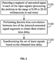
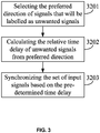
- Step 300 can be implemented by four different methods. Step 300 will be described in details with reference to FIGS. 2 , 3 , 4 , and 5 as follows:
- step 3101 is implemented to intercept two or more discrete segments of the unwanted signals, and each of the discrete segment is n milliseconds in duration.
- n needs to be greater than 0.98 ms and less than 20.03 ms.
- the duration time falls within this interval, humans cannot hear the echo while ensuring the accuracy of the signal interception. Therefore, the real-time processing is optimal, and the user has the best hearing effect.
- step 3101 continuously intercepts the discrete segments of each of the multiple signals in real time.
- the method according to the embodiment can process the time-domain signals in real time.
- Each of the discrete segments of the multiple signals at every n milliseconds is determined by pattern recognition whether each of the discrete segments is an unwanted signal or not, and then the unwanted signals are further extracted.
- there are two sound sources comprising a male and a female, in which the male voice is viewed as the unwanted signal.
- the pattern recognition automatically recognizes whether each of the discrete segments of every n milliseconds of the multiple signals comprises the male voice. If one of the discrete segments appears the male voice, the discrete segment is extracted and proceed to the next step. If the female voice is viewed as an unwanted signal, the discrete segment appearing the female voice is extracted and proceed to the next step.
- the two sound sources comprise a human voice and a non-human voice.
- the unwanted signal can be detected by monitoring whether the unwanted signal transitions from a low level to a high level in n milliseconds (i.e., a step function). For example, a male voice is viewed as an unwanted signal. When a man speaks, he doesn't need to say phonemes together to form the sound of the whole word. When the discrete segments in which the male voice appears are detected, illustrating that the voice is the unwanted signal. This approach largely reduces the need for complicated noise (such as sound signals) detection processes and thus reduces the computational complexity and cost.
- a discrete-time convolution of two detected segments of unwanted signals is calculated to obtain a time delay between them.
- mx is the average value of x
- my is the average value of y
- d is the time delay.
- the numerator part of the formula is the discrete-time convolution.
- r d ⁇ i x i ⁇ mx ⁇ y i ⁇ d ⁇ my ⁇ i x i ⁇ mx 2 ⁇ i y i ⁇ d ⁇ my 2 where the time delay d is the maximum value from r (d).
- the set of input signals are synchronized based on the obtained time delay d. For example, if the time delay between the detected unwanted signal segment in a first input signal fi(t) and the detected unwanted signal segment in a second input signal f 2 (t) is determined to be ⁇ , the first input signal f 1 (t) is synchronized to be fi(t-5). For another example, if the time delay between the detected unwanted signal segment in the first input signal fi(t) and the detected unwanted signal segment in the second input signal f 2 (t) is determined to be - ⁇ , the first input signal fi(t) is synchronized to be fi(t+5). Since the segments of the unwanted signals are continuously monitored in this embodiment in real time, the approach can continuously update the time delay during the iteration and dynamically track the change to the unwanted signal, as the signal sources and the transducers move in different directions or move with respect to each other.
- the unwanted signal is received at mutually distanced locations.
- the position of each of the unwanted signals with respect to the transducers are calculated, that is: the relative delays of each of the unwanted signals.
- the unwanted signals are determined according to the relative delay of each of the unwanted signals.
- the unwanted signals can also be determined by users in real time.
- Max dir Fs * d / v
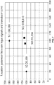
- the sampling rate (Fs) is 48 kHz
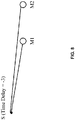
- the distance (d) between the two transducers is 2.47cm. Since the propagation speed of sound in the air (v) is 340m / s, and thus the maximum delay is 3. Therefore, the whole region can be divided into 7 areas with time delays of -3, -2, -1, 0, 1, 2, and 3, respectively. For example, referring to FIG. 8 , if a preset unwanted signal comes from an area with a time delay of -3, the delay is assigned a value of -3.
- a time delay is determined according to an unwanted signal area selected by users in real time, or a preset unwanted signal area.
- step 3203 the time delays obtained in step 3202 are synchronized according to step 3103.
- the unwanted signals from all the relative delays are employed in this embodiment.
- all the time delays are analyzed and calculated based on different signals (such as sound signals), the distance between transducers, and the propagation speed of the signal.
- step3302 all the possible time delays T1, T2, ..., Tn are determined.
- each of the different delays are synchronized again according to step 3103.
- the direction of the wanted signal can also be preset, or selected by users in real time.
- step 3402 the time delays in these directions are calculated.
- step 3403 based on the method to obtain all of the signal directions in FIG. 4 , at step 3403, the time delays of these wanted signals are removed from all of the possible directions, and each of the remaining different time delays is synchronized again according to step 3103.
- the synchronized input signals are separated into the channels with unwanted signal and channels without unwanted signals.
- step 400 is implemented by a multiplication between matrix of synchronized signals and matrix of coefficients resulted from step 200.
- step 500 How to choose between these two channels is explained in detail in step 500.
- the matrix of the mixed signals synchronized with S2 is multiplied with the coefficient matrix. Then the result is output through a suitable channel.
- step 500 for the two channels resulted from step 400, one of which with relatively lower signal energy can be selected as an output channel.
- the method to calculate signal energy is to obtain the root mean square value of the signals. The selection process will be applied to the channels with unwanted signal and channels without unwanted signals resulted from step 500.
- the output channel will be generated at different time delays.
- the output channel is an optimal channel selected based on feature detection (for example, the optimal channel is a channel with the smallest number of unwanted signals in the generated channels).
- the output channel is an optimal channel selected based on signal energy (for example, the optimal channel is a channel with the minimum amount of energy of unwanted signals in the generated channels).
- the unwanted signals are appropriately removed, subsequent processing can be performed on the separated target unwanted signal and the wanted signal.
- the wanted signal may be selectively amplified and the target unwanted signals may be selectively reduced to improve the perception of the signals.
- the disclosure provides a device comprising a processor and an interface with human-computer interaction.
- the device also includes, but is not limited to, a memory, a processor, an input/output module, and an information receiving module.
- the processor is configured to perform the above steps 100, 200, 3201-3203 (or 3401-3403), 400 and 500, and to enhance the frequency domain (optional). Users select an unwanted signal area in real time through the interface with human-computer interaction.
- the interface with human-computer interaction includes, but is not limited to, a voice receiving module, a transducer, a video receiving module, a touch screen, a keyboard, buttons, knobs, a projection interface, and a virtual 3D interface.
- the selection methods for users in real time by using the interface with human-computer interaction include the use of voice instructions, different gestures or actions, and areas with different labels selected by users.
- the interface with human-computer interaction is a touch screen where the user can click on any area.
- the disclosure provides a device for removing a target unwanted signal.
- the device is user-controllable and user-selectable, and can adjust the time delay in real time.
- steps 100-400 may be performed in a different order than that described in the drawings.
- steps 100 and 300 in the second embodiment i.e. steps 3201-3203
- steps 3201-3203 can be performed in reversed order.
- any two steps in steps 100-400 can be performed in parallel or in reverse order according to the functions involved.
- step 200 is performed prior to step 300, that is: the coefficient matrix is calculated and then the input signal is synchronized in the time domain, which provides the advantages that the coefficient matrix will not be recalculated although the time delays are different, and thus a large number of calculation is omitted.
- the result can be obtained by calculating the coefficient matrix just one time.
- the disclosure draws the following conclusions from a large number of experiments: The coefficient matrix calculated from the synchronized mixed signal is almost the same as that calculated from the original mixed signal, illustrating that the method omits a large amount of calculation without losing the accuracy of the coefficient matrix.
- the input signals received by one or more signal receiving devices can be removed according to a given criterion.
- the input signal is a sound signal
- the receiving device is a device (such as a microphone) for receiving sound signals.
- the criterion is Fs*X/V ⁇ L/3 (where L is the length of the intercepted discrete signals, X is the distance between any two receiving devices for receiving sound signals, V is the propagation speed of signal, and Fs is the sampling rate)
- the sound signals received by one of the receiving devices is removed.
- the embodiment omits a large number of complex calculation while ensuring the accuracy of the pattern recognition, improves the calculation efficiency, and optimizes the power consumption.
- the signals in the art could be referred to audio signals, image signals, electro-magnetic signals, brain wave signals, electric signals, radio wave signals or other forms of signals that could be picked up by transducers and the disclosure has no limitation in this aspect.
- the perception of the target signals can be improved while reducing the computational cost.
- the input signals are synchronized in time domain and thus the method according to the disclosure will introduce minimal frequency distortion.
- FIG. 6 a structural schematic diagram of a computer system 3000 adapted to implement an embodiment of the disclosure is shown.
- the computer system 3000 includes a central processing unit (CPU) 3001, which may execute various appropriate actions and processes in accordance with a program stored in an electronically programmable read-only memory (EPROM) 3002 or a program loaded into a random access memory (RAM).
- the RAM 3003 also stores various programs and data required by operations of the system 3000.
- the CPU 3001, the EPROM 3002 and the RAM 3003 are connected to each other through a bus 3004.
- An input/output (I/O) interface 3005 is also connected to the bus 3004.
- a Direct Memory Access interface 3006 is connected to the bus 3004 to enable fast data exchange.
- the following components may be connected to the I/O interface 3005: an removable data storage 3007 comprising USB storage, solid state drive, hard drive etc.; a wireless data link 3008 comprising LAN, blue-tooth, near field communication devices; a signal convertor 3009 which are connected to data input channel(s) 3010 and data output channel(s) 3011.
- an embedded computer system similar to the computer system 3000 but without keyboard, mouse, and hard disk. Update of programs will be facilitated via a wireless data link 3008 or removable data storage 3007.
- the central processing unit can be a cloud processor, and the memory can be a cloud memory.
- an embodiment of the disclosure comprises a computer program product, which comprises a computer program that is tangibly embodied in a machine-readable medium.
- the computer program comprises program codes for executing the method as shown in the flow charts.
- the computer program may be downloaded and installed from a network via the wireless data link 3008, and/or may be installed from the removable media 3007.
- each of the blocks in the flow charts and block diagrams may represent a module, a program segment, or a code portion.
- the module, the program segment, or the code portion comprises one or more executable instructions for implementing the specified logical function.
- the functions denoted by the blocks may occur in a different sequence from that the sequence as shown in the figures. For example, in practice, two blocks in succession may be executed substantially in parallel, or in a reverse order, depending on the functionalities involved.
- each block in the block diagrams and/or the flow charts and/or a combination of the blocks may be implemented by a dedicated hardware-based system executing specific functions or operations, or by a combination of a dedicated hardware and computer instructions.
- the units or modules involved in the embodiments of the disclosure may be implemented by way of software or hardware.
- the described units or modules may also be provided in a processor.
- the names of these units or modules are not considered as a limitation to the units or modules.
- the disclosure also provides a computer readable storage medium.
- the computer readable storage medium may be the computer readable storage medium included in the apparatus in the above embodiments, and it may also be a separate computer readable storage medium which has not been assembled into the apparatus.
- the computer readable storage medium stores one or more programs, which are used by one or more processors to execute the method for separating a target signal from noise described in the disclosure.
Landscapes
- Engineering & Computer Science (AREA)
- Signal Processing (AREA)
- Acoustics & Sound (AREA)
- Physics & Mathematics (AREA)
- Health & Medical Sciences (AREA)
- Otolaryngology (AREA)
- General Health & Medical Sciences (AREA)
- Neurosurgery (AREA)
- Computational Linguistics (AREA)
- Quality & Reliability (AREA)
- Audiology, Speech & Language Pathology (AREA)
- Human Computer Interaction (AREA)
- Multimedia (AREA)
- Circuit For Audible Band Transducer (AREA)
Applications Claiming Priority (2)
| Application Number | Priority Date | Filing Date | Title |
|---|---|---|---|
| CN201710698651.6A CN109413543B (zh) | 2017-08-15 | 2017-08-15 | 一种源信号提取方法、系统和存储介质 |
| PCT/CN2017/117813 WO2019033671A1 (fr) | 2017-08-15 | 2017-12-21 | Procédé et système d'extraction de signal source, et support de stockage |
Publications (2)
| Publication Number | Publication Date |
|---|---|
| EP3672275A1 true EP3672275A1 (fr) | 2020-06-24 |
| EP3672275A4 EP3672275A4 (fr) | 2023-08-23 |
Family
ID=65362112
Family Applications (1)
| Application Number | Title | Priority Date | Filing Date |
|---|---|---|---|
| EP17921701.3A Withdrawn EP3672275A4 (fr) | 2017-08-15 | 2017-12-21 | Procédé et système d'extraction de signal source, et support de stockage |
Country Status (3)
| Country | Link |
|---|---|
| EP (1) | EP3672275A4 (fr) |
| CN (1) | CN109413543B (fr) |
| WO (1) | WO2019033671A1 (fr) |
Family Cites Families (19)
| Publication number | Priority date | Publication date | Assignee | Title |
|---|---|---|---|---|
| CN100372277C (zh) * | 2006-02-20 | 2008-02-27 | 东南大学 | 基于空域预白化合并的空时分离软输入软输出检测方法 |
| CN100495388C (zh) * | 2006-10-10 | 2009-06-03 | 深圳市理邦精密仪器有限公司 | 一种利用空间坐标转换实现信号分离的信号处理方法 |
| EP2430975A1 (fr) * | 2010-09-17 | 2012-03-21 | Stichting IMEC Nederland | Analyse de composantes principales ou de composantes indépendantes pour l'électrocardiographie ambulatoire |
| US9100734B2 (en) * | 2010-10-22 | 2015-08-04 | Qualcomm Incorporated | Systems, methods, apparatus, and computer-readable media for far-field multi-source tracking and separation |
| CN102571296B (zh) * | 2010-12-07 | 2014-09-03 | 华为技术有限公司 | 一种预编码的方法及装置 |
| JP2012234150A (ja) * | 2011-04-18 | 2012-11-29 | Sony Corp | 音信号処理装置、および音信号処理方法、並びにプログラム |
| US9099096B2 (en) * | 2012-05-04 | 2015-08-04 | Sony Computer Entertainment Inc. | Source separation by independent component analysis with moving constraint |
| US8880395B2 (en) * | 2012-05-04 | 2014-11-04 | Sony Computer Entertainment Inc. | Source separation by independent component analysis in conjunction with source direction information |
| JP2014045793A (ja) * | 2012-08-29 | 2014-03-17 | Sony Corp | 信号処理システム、信号処理装置及びプログラム |
| CN102868433B (zh) * | 2012-09-10 | 2015-04-08 | 西安电子科技大学 | 多输入多输出y信道中基于天线选择的信号传输方法 |
| CN103083012A (zh) * | 2012-12-24 | 2013-05-08 | 太原理工大学 | 基于盲源分离的房颤信号提取方法 |
| CN103197183B (zh) * | 2013-01-11 | 2015-08-19 | 北京航空航天大学 | 一种修正电磁干扰分离中独立分量分析法不确定度的方法 |
| CN104053107B (zh) * | 2014-06-06 | 2018-06-05 | 重庆大学 | 一种用于噪声环境下声源分离和定位方法 |
| CN104091356A (zh) * | 2014-07-04 | 2014-10-08 | 南京邮电大学 | 基于独立分量分析的x射线医学图像目标重建 |
| WO2017084397A1 (fr) * | 2015-11-19 | 2017-05-26 | The Hong Kong University Of Science And Technology | Procédé, système, et support de stockage pour une séparation de signaux |
| CN105640500A (zh) * | 2015-12-21 | 2016-06-08 | 安徽大学 | 基于独立分量分析的扫视信号特征提取方法和识别方法 |
| CN105996993A (zh) * | 2016-04-29 | 2016-10-12 | 南京理工大学 | 一种智能视频生命体征监测系统及方法 |
| CN106356075B (zh) * | 2016-09-29 | 2019-09-17 | 合肥美的智能科技有限公司 | 盲音分离方法、结构及语音控制系统和电器总成 |
| CN107025446A (zh) * | 2017-04-12 | 2017-08-08 | 北京信息科技大学 | 一种振动信号联合降噪方法 |
-
2017
- 2017-08-15 CN CN201710698651.6A patent/CN109413543B/zh active Active
- 2017-12-21 EP EP17921701.3A patent/EP3672275A4/fr not_active Withdrawn
- 2017-12-21 WO PCT/CN2017/117813 patent/WO2019033671A1/fr not_active Ceased
Also Published As
| Publication number | Publication date |
|---|---|
| EP3672275A4 (fr) | 2023-08-23 |
| CN109413543B (zh) | 2021-01-19 |
| WO2019033671A1 (fr) | 2019-02-21 |
| CN109413543A (zh) | 2019-03-01 |
Similar Documents
| Publication | Publication Date | Title |
|---|---|---|
| US9668066B1 (en) | Blind source separation systems | |
| EP3655949B1 (fr) | Systèmes de séparation de source acoustique | |
| Mandel et al. | An EM algorithm for localizing multiple sound sources in reverberant environments | |
| EP2393463B1 (fr) | Filtre de tonalité directionel a microphones multiples | |
| JP6400218B2 (ja) | オーディオ源の分離 | |
| US10650841B2 (en) | Sound source separation apparatus and method | |
| CN106233382B (zh) | 一种对若干个输入音频信号进行去混响的信号处理装置 | |
| GB2548325A (en) | Acoustic source seperation systems | |
| CN103811023B (zh) | 音频处理装置以及音频处理方法 | |
| CN102447993A (zh) | 声音场景操纵 | |
| EP3133833B1 (fr) | Appareil, procédé et programme de reproduction de champ sonore | |
| EP2437517B1 (fr) | Manipulation de scène sonore | |
| Hosseini et al. | Time difference of arrival estimation of sound source using cross correlation and modified maximum likelihood weighting function | |
| Dang et al. | An iteratively reweighted steered response power approach to multisource localization using a distributed microphone network | |
| US11277210B2 (en) | Method, system and storage medium for signal separation | |
| JPWO2016076237A1 (ja) | 信号処理装置、信号処理方法および信号処理プログラム | |
| Douglas | Blind separation of acoustic signals | |
| Anemüller et al. | Adaptive separation of acoustic sources for anechoic conditions: A constrained frequency domain approach | |
| US11823698B2 (en) | Audio cropping | |
| EP3672275A1 (fr) | Procédé et système d'extraction de signal source, et support de stockage | |
| JP2003078423A (ja) | ブラインド信号分離処理装置 | |
| JP4462063B2 (ja) | 音声処理装置 | |
| WO2023001850A1 (fr) | Séparation et recadrage de signal audio | |
| Cobos et al. | Two-microphone separation of speech mixtures based on interclass variance maximization | |
| JP2010217268A (ja) | 音源方向知覚が可能な両耳信号を生成する低遅延信号処理装置 |
Legal Events
| Date | Code | Title | Description |
|---|---|---|---|
| STAA | Information on the status of an ep patent application or granted ep patent |
Free format text: STATUS: THE INTERNATIONAL PUBLICATION HAS BEEN MADE |
|
| PUAI | Public reference made under article 153(3) epc to a published international application that has entered the european phase |
Free format text: ORIGINAL CODE: 0009012 |
|
| STAA | Information on the status of an ep patent application or granted ep patent |
Free format text: STATUS: REQUEST FOR EXAMINATION WAS MADE |
|
| 17P | Request for examination filed |
Effective date: 20200315 |
|
| AK | Designated contracting states |
Kind code of ref document: A1 Designated state(s): AL AT BE BG CH CY CZ DE DK EE ES FI FR GB GR HR HU IE IS IT LI LT LU LV MC MK MT NL NO PL PT RO RS SE SI SK SM TR |
|
| AX | Request for extension of the european patent |
Extension state: BA ME |
|
| DAV | Request for validation of the european patent (deleted) | ||
| DAX | Request for extension of the european patent (deleted) | ||
| 19U | Interruption of proceedings before grant |
Effective date: 20200316 |
|
| 19W | Proceedings resumed before grant after interruption of proceedings |
Effective date: 20210406 |
|
| R17P | Request for examination filed (corrected) |
Effective date: 20200315 |
|
| REG | Reference to a national code |
Ref country code: DE Ref legal event code: R079 Free format text: PREVIOUS MAIN CLASS: H04R0003000000 Ipc: G10L0021027200 |
|
| A4 | Supplementary search report drawn up and despatched |
Effective date: 20230726 |
|
| RIC1 | Information provided on ipc code assigned before grant |
Ipc: H04R 1/40 20060101ALN20230720BHEP Ipc: H04R 25/00 20060101ALI20230720BHEP Ipc: H04R 3/00 20060101ALI20230720BHEP Ipc: G10L 21/0272 20130101AFI20230720BHEP |
|
| STAA | Information on the status of an ep patent application or granted ep patent |
Free format text: STATUS: THE APPLICATION IS DEEMED TO BE WITHDRAWN |
|
| 18D | Application deemed to be withdrawn |
Effective date: 20240227 |