EP3672343B1 - Resource using method of node in wireless communication system and node using same method - Google Patents
Resource using method of node in wireless communication system and node using same method Download PDFInfo
- Publication number
- EP3672343B1 EP3672343B1 EP19842851.8A EP19842851A EP3672343B1 EP 3672343 B1 EP3672343 B1 EP 3672343B1 EP 19842851 A EP19842851 A EP 19842851A EP 3672343 B1 EP3672343 B1 EP 3672343B1
- Authority
- EP
- European Patent Office
- Prior art keywords
- resource
- node
- soft
- allocation information
- iab
- Prior art date
- Legal status (The legal status is an assumption and is not a legal conclusion. Google has not performed a legal analysis and makes no representation as to the accuracy of the status listed.)
- Active
Links
Images






Classifications
-
- H—ELECTRICITY
- H04—ELECTRIC COMMUNICATION TECHNIQUE
- H04W—WIRELESS COMMUNICATION NETWORKS
- H04W72/00—Local resource management
- H04W72/20—Control channels or signalling for resource management
- H04W72/27—Control channels or signalling for resource management between access points
-
- H—ELECTRICITY
- H04—ELECTRIC COMMUNICATION TECHNIQUE
- H04L—TRANSMISSION OF DIGITAL INFORMATION, e.g. TELEGRAPHIC COMMUNICATION
- H04L5/00—Arrangements affording multiple use of the transmission path
- H04L5/003—Arrangements for allocating sub-channels of the transmission path
- H04L5/0044—Allocation of payload; Allocation of data channels, e.g. PDSCH or PUSCH
-
- H—ELECTRICITY
- H04—ELECTRIC COMMUNICATION TECHNIQUE
- H04B—TRANSMISSION
- H04B7/00—Radio transmission systems, i.e. using radiation field
- H04B7/14—Relay systems
- H04B7/15—Active relay systems
- H04B7/155—Ground-based stations
- H04B7/15528—Control of operation parameters of a relay station to exploit the physical medium
- H04B7/15542—Selecting at relay station its transmit and receive resources
-
- H—ELECTRICITY
- H04—ELECTRIC COMMUNICATION TECHNIQUE
- H04L—TRANSMISSION OF DIGITAL INFORMATION, e.g. TELEGRAPHIC COMMUNICATION
- H04L5/00—Arrangements affording multiple use of the transmission path
- H04L5/0091—Signalling for the administration of the divided path, e.g. signalling of configuration information
- H04L5/0092—Indication of how the channel is divided
-
- H—ELECTRICITY
- H04—ELECTRIC COMMUNICATION TECHNIQUE
- H04W—WIRELESS COMMUNICATION NETWORKS
- H04W72/00—Local resource management
- H04W72/04—Wireless resource allocation
- H04W72/044—Wireless resource allocation based on the type of the allocated resource
- H04W72/0446—Resources in time domain, e.g. slots or frames
-
- H—ELECTRICITY
- H04—ELECTRIC COMMUNICATION TECHNIQUE
- H04W—WIRELESS COMMUNICATION NETWORKS
- H04W72/00—Local resource management
- H04W72/20—Control channels or signalling for resource management
-
- H—ELECTRICITY
- H04—ELECTRIC COMMUNICATION TECHNIQUE
- H04W—WIRELESS COMMUNICATION NETWORKS
- H04W72/00—Local resource management
- H04W72/50—Allocation or scheduling criteria for wireless resources
- H04W72/53—Allocation or scheduling criteria for wireless resources based on regulatory allocation policies
-
- H—ELECTRICITY
- H04—ELECTRIC COMMUNICATION TECHNIQUE
- H04W—WIRELESS COMMUNICATION NETWORKS
- H04W84/00—Network topologies
- H04W84/02—Hierarchically pre-organised networks, e.g. paging networks, cellular networks, WLAN [Wireless Local Area Network] or WLL [Wireless Local Loop]
- H04W84/04—Large scale networks; Deep hierarchical networks
- H04W84/042—Public Land Mobile systems, e.g. cellular systems
- H04W84/047—Public Land Mobile systems, e.g. cellular systems using dedicated repeater stations
-
- H—ELECTRICITY
- H04—ELECTRIC COMMUNICATION TECHNIQUE
- H04W—WIRELESS COMMUNICATION NETWORKS
- H04W92/00—Interfaces specially adapted for wireless communication networks
- H04W92/16—Interfaces between hierarchically similar devices
- H04W92/20—Interfaces between hierarchically similar devices between access points
-
- H—ELECTRICITY
- H04—ELECTRIC COMMUNICATION TECHNIQUE
- H04L—TRANSMISSION OF DIGITAL INFORMATION, e.g. TELEGRAPHIC COMMUNICATION
- H04L5/00—Arrangements affording multiple use of the transmission path
- H04L5/0001—Arrangements for dividing the transmission path
- H04L5/0026—Division using four or more dimensions, e.g. beam steering or quasi-co-location [QCL]
-
- H—ELECTRICITY
- H04—ELECTRIC COMMUNICATION TECHNIQUE
- H04L—TRANSMISSION OF DIGITAL INFORMATION, e.g. TELEGRAPHIC COMMUNICATION
- H04L5/00—Arrangements affording multiple use of the transmission path
- H04L5/003—Arrangements for allocating sub-channels of the transmission path
- H04L5/0048—Allocation of pilot signals, i.e. of signals known to the receiver
-
- H—ELECTRICITY
- H04—ELECTRIC COMMUNICATION TECHNIQUE
- H04L—TRANSMISSION OF DIGITAL INFORMATION, e.g. TELEGRAPHIC COMMUNICATION
- H04L5/00—Arrangements affording multiple use of the transmission path
- H04L5/14—Two-way operation using the same type of signal, i.e. duplex
- H04L5/1438—Negotiation of transmission parameters prior to communication
-
- H—ELECTRICITY
- H04—ELECTRIC COMMUNICATION TECHNIQUE
- H04L—TRANSMISSION OF DIGITAL INFORMATION, e.g. TELEGRAPHIC COMMUNICATION
- H04L5/00—Arrangements affording multiple use of the transmission path
- H04L5/14—Two-way operation using the same type of signal, i.e. duplex
- H04L5/16—Half-duplex systems; Simplex/duplex switching; Transmission of break signals non-automatically inverting the direction of transmission
-
- H—ELECTRICITY
- H04—ELECTRIC COMMUNICATION TECHNIQUE
- H04W—WIRELESS COMMUNICATION NETWORKS
- H04W72/00—Local resource management
- H04W72/50—Allocation or scheduling criteria for wireless resources
- H04W72/54—Allocation or scheduling criteria for wireless resources based on quality criteria
- H04W72/541—Allocation or scheduling criteria for wireless resources based on quality criteria using the level of interference
Definitions
- the disclosure relates to wireless communication and, more particularly, to a resource use method of a node in a wireless communication system and a node using the same.
- a wider bandwidth may be used in NR than in Long-Term Evolution (LTE). Further, in NR, massive multiple-input and multiple-output (MIMO) and a multibeam may be used.
- MIMO massive multiple-input and multiple-output
- a multibeam may be used.
- an IAB node may operate like a mobile terminal (MT) in a relationship with a parent node, and may operate like a distributed unit (DU), that is, a base station, in a relationship with a child node. Accordingly, for resource allocation for the IAB node, resource allocation in terms of the MT and resource allocation in terms of the DU may be performed.
- MT mobile terminal
- DU distributed unit
- the resource may be considered to be used for the communication with the parent node.
- the resource may be considered to be used for the communication with the child node.
- the first allocation information and the second allocation information may be received from the parent node.
- the child node may be a UE connected to the node.
- a node according to claim 11 In another aspect, provided is a node according to claim 11.
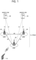
- FIG. 1 shows a conventional wireless communication system.
- the wireless communication system may be referred to as an Evolved-UMTS Terrestrial Radio Access Network (E-UTRAN) or a Long Term Evolution (LTE)/LTE-A system, for example.
- E-UTRAN Evolved-UMTS Terrestrial Radio Access Network
- LTE Long Term Evolution
- LTE-A Long Term Evolution
- the E-UTRAN includes at least one base station (BS) 20 which provides a control plane and a user plane to a user equipment (UE) 10.
- the UE 10 may be fixed or mobile, and may be referred to as another terminology, such as a mobile station (MS), a user terminal (UT), a subscriber station (SS), a mobile terminal (MT), a wireless device, etc.
- the BS 20 is generally a fixed station that communicates with the UE 10 and may be referred to as another terminology, such as an evolved node-B (eNB), a base transceiver system (BTS), an access point, etc.
- eNB evolved node-B
- BTS base transceiver system
- access point etc.
- the BSs 20 are interconnected by means of an X2 interface.
- the BSs 20 are also connected by means of an S1 interface to an evolved packet core (EPC) 30, more specifically, to a mobility management entity (MME) through S1-MME and to a serving gateway (S-GW) through S 1-U.
- EPC evolved packet core
- MME mobility management entity
- S-GW serving gateway
- the EPC 30 includes an MME, an S-GW, and a packet data network-gateway (P-GW).
- the MME has access information of the UE or capability information of the UE, and such information is generally used for mobility management of the UE.
- the S-GW is a gateway having an E-UTRAN as an end point.
- the P-GW is a gateway having a PDN as an end point.
- Layers of a radio interface protocol between the UE and the network can be classified into a first layer (L1), a second layer (L2), and a third layer (L3) based on the lower three layers of the open system interconnection (OSI) model that is well-known in the communication system.
- a physical (PHY) layer belonging to the first layer provides an information transfer service by using a physical channel
- a radio resource control (RRC) layer belonging to the third layer serves to control a radio resource between the UE and the network.
- the RRC layer exchanges an RRC message between the UE and the BS.
- An existing wireless communication system may be replaced or coexist with a system using a new radio access technology (new RAT) (or a new radio (NR) system).
- new RAT new radio access technology
- NR new radio
- next generation communications As communication devices have increasingly required greater communication capacity, the necessity for improved mobile broadband communication, relative to an existing radio access technology (RAT), has emerged. Also, massive machine type communications (MTC), which provides many different services by connecting multiple devices and objects, is also one of the major issues to be considered in next generation communications. In addition, a communication system design considering services or terminals vulnerable to reliability or latency has also been discussed. An introduction of a next-generation RAT considering enhanced mobile broadband communication, massive MTC, ultra-reliable and low latency communication (URLLC), and the like, has been discussed, and in this disclosure, for the purposes of description, the corresponding technology will be termed new RAT or new radio (NR).
- NR new radio
- FIG. 2 illustrates a system structure of a next generation radio access network (NG-RAN) to which NR is applied.
- NG-RAN next generation radio access network
- the transmitting device 10 and the receiving device 20 may respectively include transceivers 13 and 23 capable of transmitting or receiving radio frequency (RF) signals carrying information, data, signals and messages, memories 12 and 22 for storing various types of information regarding communication in a wireless communication system, and processors 11 and 21 connected to components such as the transceivers 13 and 23 and the memories 12 and 22 and configured to control the memories 12 and 22 and/or the transceivers 13 and 23 such that the corresponding devices perform at least one of embodiments of the present disclosure.
- RF radio frequency
- the memories 12 and 22 can store programs for processing and control of the processors 11 and 21 and temporarily store input/output information.
- the memories 12 and 22 may be used as buffers.
- firmware or software may be configured to include modules, procedures or functions for performing functions or operations of the present disclosure, and the firmware or software configured to implement the present disclosure may be included in the processors 11 and 21 or stored in the memories 12 and 22 and executed by the processors 11 and 21.
- the processor 11 of the transmitting device 10 can perform predetermined coding and modulation on a signal and/or data to be transmitted to the outside and then transmit the signal and/or data to the transceiver 13.
- the processor 11 can perform demultiplexing, channel coding, scrambling and modulation on a data string to be transmitted to generate a codeword.
- the codeword can include information equivalent to a transport block which is a data block provided by an MAC layer.
- One transport block (TB) can be coded into one codeword.
- Each codeword can be transmitted to the receiving device through one or more layers.
- the transceiver 13 may include an oscillator for frequency up-conversion.
- the transceiver 13 may include one or multiple transmission antennas.
- the signal processing procedure of the receiving device 20 may be reverse to the signal processing procedure of the transmitting device 10.
- the transceiver 23 of the receiving device 20 can receive RF signals transmitted from the transmitting device 10 under the control of the processor 21.
- the transceiver 23 may include one or multiple reception antennas.
- the transceiver 23 can frequency-down-convert signals received through the reception antennas to restore baseband signals.
- the transceiver 23 may include an oscillator for frequency down conversion.
- the processor 21 can perform decoding and demodulation on RF signals received through the reception antennas to restore data that is intended to be transmitted by the transmitting device 10.
- the transceivers 13 and 23 may include one or multiple antennas.
- the antennas can transmit signals processed by the transceivers 13 and 23 to the outside or receive RF signals from the outside and deliver the RF signal to the transceivers 13 and 23 under the control of the processors 11 and 21 according to an embodiment of the present disclosure.
- the antennas may be referred to as antenna ports.
- Each antenna may correspond to one physical antenna or may be configured by a combination of a plurality of physical antenna elements. A signal transmitted from each antenna cannot be decomposed by the receiving device 20.
- a reference signal (RS) transmitted corresponding to an antenna defines an antenna from the viewpoint of the receiving device 20 and can allow the receiving device 20 to be able to estimate a channel with respect to the antenna irrespective of whether the channel is a single radio channel from a physical antenna or a composite channel from a plurality of physical antenna elements including the antenna. That is, an antenna can be defined such that a channel carrying a symbol on the antenna can be derived from the channel over which another symbol on the same antenna is transmitted.
- a transceiver which supports a multi-input multi-output (MIMO) function of transmitting and receiving data using a plurality of antennas may be connected to two or more antennas.
- MIMO multi-input multi-output
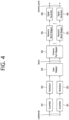
- FIG. 4 illustrates an example of a signal processing module structure in the transmitting device 10.
- signal processing can be performed by a processor of a base station/terminal, such as the processor 11 of FIG. 3 .
- the transmitting device 10 included in a terminal or a base station may include scramblers 301, modulators 302, a layer mapper 303, an antenna port mapper 304, resource block mappers 305 and signal generators 306.
- the transmitting device 10 can transmit one or more codewords. Coded bits in each codeword are scrambled by the corresponding scrambler 301 and transmitted over a physical channel.
- a codeword may be referred to as a data string and may be equivalent to a transport block which is a data block provided by the MAC layer.
- Each resource block mapper 305 can map complex-valued modulation symbols with respect to each antenna port to appropriate resource elements in a virtual resource block allocated for transmission.
- the resource block mapper can map the virtual resource block to a physical resource block according to an appropriate mapping scheme.
- the resource block mapper 305 can allocate complex-valued modulation symbols with respect to each antenna port to appropriate subcarriers and multiplex the complex-valued modulation symbols according to a user.
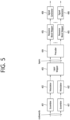
- the transmitting device 10 included in a terminal or a base station may include scramblers 401, modulators 402, a layer mapper 403, a precoder 404, resource block mappers 405 and signal generators 406.
- Scrambled bits are modulated into complex-valued modulation symbols by the corresponding modulator 402.
- the modulator can modulate the scrambled bits according to a predetermined modulation scheme to arrange complex-valued modulation symbols representing positions on a signal constellation.
- the modulation scheme is not limited and pi/2-BPSK (pi/2-Binary Phase Shift Keying), m-PSK (m-Phase Shift Keying) or m-QAM (m-Quadrature Amplitude Modulation) may be used to modulate the coded data.
- the complex-valued modulation symbols can be mapped to one or more transport layers by the layer mapper 403.
- Each resource block mapper 405 maps complex-valued modulation symbols with respect to each antenna port to appropriate resource elements in a virtual resource block allocated for transmission.
- the resource block mapper 405 can allocate complex-valued modulation symbols to appropriate subcarriers and multiplex the complex-valued modulation symbols according to a user.
- Each signal generator 406 can modulate complex-valued modulation symbols according to a specific modulation scheme, for example, OFDM, to generate a complex-valued time domain OFDM symbol signal.
- the signal generator 406 can perform IFFT (Inverse Fast Fourier Transform) on antenna-specific symbols, and a CP (cyclic Prefix) can be inserted into time domain symbols on which IFFT has been performed. OFDM symbols are subjected to digital-analog conversion and frequency up-conversion and then transmitted to the receiving device through each transmission antenna.
- the signal generator 406 may include an IFFT module, a CP inserting unit, a digital-to-analog converter (DAC) and a frequency upconverter.
- DAC digital-to-analog converter
- the signal processing procedure of the receiving device 20 may be reverse to the signal processing procedure of the transmitting device.
- the processor 21 of the transmitting device 10 decodes and demodulates RF signals received through antenna ports of the transceiver 23.
- the receiving device 20 may include a plurality of reception antennas, and signals received through the reception antennas are restored to baseband signals, and then multiplexed and demodulated according to MIMO to be restored to a data string intended to be transmitted by the transmitting device 10.
- the receiving device 20 may include a signal restoration unit which restores received signals to baseband signals, a multiplexer for combining and multiplexing received signals, and a channel demodulator for demodulating multiplexed signal strings into corresponding codewords.
- the signal restoration unit, the multiplexer and the channel demodulator may be configured as an integrated module or independent modules for executing functions thereof. More specifically, the signal restoration unit may include an analog-to-digital converter (ADC) for converting an analog signal into a digital signal, a CP removal which removes a CP from the digital signal, an FET module for applying FFT (fast Fourier transform) to the signal from which the CP has been removed to output frequency domain symbols, and a resource element demapper/equalizer for restoring the frequency domain symbols to antenna-specific symbols.
- ADC analog-to-digital converter
- FET module for applying FFT (fast Fourier transform) to the signal from which the CP has been removed to output frequency domain symbols
- a resource element demapper/equalizer for restoring the frequency domain symbols to antenna-specific symbols.
- the antenna-specific symbols are restored to transport layers by the multiplexer and the transport layers are restored by the channel demodulator to codewords intended to be transmitted by the transmitting device.
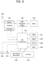
- FIG. 6 illustrates an example of a wireless communication device according to an implementation example of the present disclosure.
- the processor 2310 can implement functions, procedures and methods described in the present description.
- the processor 2310 in FIG. 6 may be the processors 11 and 21 in FIG. 3 .
- various components such as a camera and a universal serial bus (USB) port may be additionally included in the terminal.
- the camera may be connected to the processor 2310.
- FIG. 7 is a block diagram illustrating radio protocol architecture for a user plane.
- FIG. 8 is a block diagram illustrating radio protocol architecture for a control plane.
- the user plane is a protocol stack for user data transmission.
- the control plane is a protocol stack for control signal transmission.
- a PHY layer provides an upper layer with an information transfer service through a physical channel.
- the PHY layer is connected to a medium access control (MAC) layer which is an upper layer of the PHY layer through a transport channel.
- MAC medium access control
- Data is transferred between the MAC layer and the PHY layer through the transport channel.
- the transport channel is classified according to how and with what characteristics data is transmitted through a radio interface.
- a function of the RLC layer includes RLC SDU concatenation, segmentation, and reassembly.
- QoS quality of service
- the RLC layer provides three operation modes, i.e., a transparent mode (TM), an unacknowledged mode (UM), and an acknowledged mode (AM).
- TM transparent mode
- UM unacknowledged mode
- AM acknowledged mode
- the AM RLC provides error correction by using an automatic repeat request (ARQ).
- ARQ automatic repeat request
- the configuration of the RB implies a process for specifying a radio protocol layer and channel properties to provide a particular service and for determining respective detailed parameters and operations.
- the RB can be classified into two types, i.e., a signaling RB (SRB) and a data RB (DRB).
- SRB signaling RB
- DRB data RB
- the SRB is used as a path for transmitting an RRC message in the control plane.
- the DRB is used as a path for transmitting user data in the user plane.
- the UE When an RRC connection is established between an RRC layer of the UE and an RRC layer of the network, the UE is in an RRC connected state; otherwise, the UE is in an RRC idle state.
- Data is transmitted from the network to the UE through a downlink transport channel.
- the downlink transport channel include a broadcast channel (BCH) for transmitting system information and a downlink shared channel (SCH) for transmitting user traffic or control messages.
- BCH broadcast channel
- SCH downlink shared channel
- the user traffic of downlink multicast or broadcast services or the control messages can be transmitted on the downlink-SCH or an additional downlink multicast channel (MCH).
- MCH downlink multicast channel
- Data are transmitted from the UE to the network through an uplink transport channel.
- the uplink transport channel include a random access channel (RACH) for transmitting an initial control message and an uplink SCH for transmitting user traffic or control messages.
- RACH random access channel
- the physical channel includes a plurality of OFDM symbols in the time domain and a plurality of subcarriers in the frequency domain.
- One subframe includes a plurality of OFDM symbols in the time domain.
- a resource block is a resource allocation unit and includes a plurality of OFDM symbols and a plurality of subcarriers. Further, each subframe may use specific subcarriers of specific OFDM symbols (e.g., a first OFDM symbol) of the subframe for a physical downlink control channel (PDCCH), that is, an L1/L2 control channel.
- a transmission time interval (TTI) is a unit time for subframe transmission.
- FIG. 9 illustrates a frame structure applicable in NR.
- a UE may be allocated a slot format through an upper-layer signal, through DCI, or on the basis of a combination of an upper-layer signal and DCI.
- An antenna port is defined such that a channel carrying a symbol on the antenna port can be inferred from a channel carrying another symbol on the same antenna port. If large-scale properties of a channel carrying a symbol on one antenna port can be inferred from a channel carrying a symbol on another antenna port, the two antenna ports are regarded as being quasi co-located.
- the large-scale properties may include at least one of delay spread, Doppler spread, Doppler shift, average gain, average delay, and spatial Rx parameters.
- a resource grid may be defined to include a certain number of subcarriers and OFDM symbols for each numerology and carrier and may start from a common resource block indicated by upper-layer signaling.
- a resource element is each element of a resource grid for an antenna port and a subcarrier spacing configuration and may correspond to a complex value.
- a common resource block may be numbered in ascending order from zero in the frequency domain for a subcarrier spacing configuration.
- Subcarrier 0 of common resource block 0 for a subcarrier spacing configuration may correspond to reference point A.
- a physical resource block and a virtual resource block may be defined within a carrier bandwidth part and may be numbered in ascending order from zero.
- up to 15 secondary cells may be aggregated and used in addition to a primary cell. That is, up to 16 serving cells may be aggregated for a UE.
- CORESET control resource set
- FIG. 10 illustrates a CORESET
- a UE may attempt PDCCH detection in a unit of 1, 2, 4, 8, or 16 CCEs within the CORESET.
- One or a plurality of CCEs for attempting PDCCH detection may be referred to as a PDCCH candidate.
- FIG. 11 illustrates a difference between a conventional control region and a CORESET in NR.
- a control region 300 in a conventional wireless communication system is configured over the entire system bandwidth used by a base station. Excluding some UEs(e.g., eMTC/NB-IoTUEs) supporting only a narrow bandwidth, all UEsneed to be able to receive a radio signal in the entire system bandwidth of the base station in order to properly receive/decode control information transmitted by the base station.
- UEs e.g., eMTC/NB-IoTUEs
- CORESETs 301, 302, and 303 may be radio resources for control information that a UE needs to receive and may occupy only part of a system bandwidth instead of the entire system bandwidth.
- a base station may allocate a CORESET to each UE and may transmit control information through the allocated CORESET. For example, in FIG. 11 , the base station may allocate a first CORESET 301 to a first UE, may allocate a second CORESET 302 to a second UE, and may allocate a third CORESET 303 to a third UE.
- a UE in NR may receive control information froma base station even though not necessarily receiving the entire system bandwidth.
- a bandwidth part is a set of contiguous physical resource blocks (PRBs) selected from contiguous subsets of common resource blocks (CRBs) for a given numerology on a given carrier.
- PRBs physical resource blocks
- CRBs common resource blocks
- bandwidth part i may be indicated by N start BWP,I and N size BWP,i .
- N start BWP,I may indicate a starting CRB of bandwidth part i on the basis of CRB 0
- N size BWP,I may indicate the size of bandwidth part i (e.g., in PRBs) in the frequency domain.
- PRBs in each bandwidth part may be indexed from 0.
- the UE may be allocated up to four downlink bandwidth parts in a downlink, but only one downlink bandwidth part may be activated at a given time.
- the UE does not expect to receive a PDSCH, a PDCCH, a CSI-RS, or the like via a downlink bandwidth part other than the activated downlink bandwidth part among the downlink bandwidth parts.
- Each downlink bandwidth part may include at least one CORESET.
- the UE may be allocated up to four uplink bandwidth parts in an uplink, but only one uplink bandwidth part may be activated at a given time.
- the UE does not transmit a PUSCH, a PUCCH, or the like via an uplink bandwidth part other than the activated uplink bandwidth part among the uplink bandwidth parts.
- NR operates in a wider band than in a conventional system, where not all UEs can support a wideband.
- a bandwidth part (BWP) enables a UE incapable of supporting a wideband to operate.
- An initial activation downlink bandwidth part may be defined by the positions and number of adjacent PRBs, subcarrier spacing, and a CP for a control resource set for a type 0-PDCCH common search space.
- a UE may be provided with upper-layer parameters for a random access procedure.
- a UE may expect that the center frequency for a DL BWP is the same as the center frequency for a UL BWP.
- a resource allocation type specifies a method for a scheduler (e.g., a base station) to allocate resource blocks for each transmission. For example, when a base station allocates a bandwidth including a plurality of resource blocks to a UE, the base station may report the resource blocks allocated to the UE through a bitmap including bits corresponding to the respective resource blocks of the band. In this case, the flexibility of resource allocation is increased, while the amount of information used for resource allocation is also increased.
- a scheduler e.g., a base station
- RBG subset #0 may include RBGs #0, #3, #6, #9, and the like
- RBG subset #1 may include RBGs #1, #4, #7, #10, and the like
- RBG subset #2 may include RBGs #2, #5, #8, #11, and the like.
- the number of RBGs included in one RBG subset and the number of resource blocks (RBs) included in one RBG are set to be the same.
- Resource allocation type 1 indicates which RBG subset is used among RBG subsets and which RB in the RBG is used.
- Resource allocation type 2 is a method of allocating a resource by indicating the starting position (RB number) of an allocated bandwidth and the number of contiguous resource blocks.
- the contiguous resource blocks may start from the starting position.
- the contiguous resource blocks are not necessarily limited to physical contiguity but may mean that logical or virtual resource block indexes are contiguous.
- a UE receives information from a base station through a downlink (DL) and transmits information to the base station through an uplink (UL).
- Information transmitted and received between the base station and the UE includes data and various pieces of control information, and various physical channels exist according to the type/use of the transmitted and received information.
- the UE When turned-off power is turned on again or the UE enters a new cell, the UE performs an initial cell search operation, such as synchronization with the base station (S11). To this end, the UE receives a primary synchronization channel (PSCH) and a secondary synchronization channel (SSCH) from the base station, synchronizes with the base station and obtains information, such as a cell identity. Further, the UE may receive a physical broadcast channel (PBCH) from the base station to obtain in-cell broadcast information. In addition, the UE may receive a downlink reference signal (DL RS) to check a downlink channel state in the cell initial cell search operation.
- PSCH primary synchronization channel
- SSCH secondary synchronization channel
- PBCH physical broadcast channel
- DL RS downlink reference signal
- the UE may perform a general uplink/downlink signal transmission procedure of receiving a PDCCH/PDSCH (S17) and transmitting a PUSCH/physical uplink control channel (PUCCH) (S18).
- Control information transmitted from the UE to the base station is referred to as uplink control information (UCI).
- UCI includes a hybrid automatic repeat and request acknowledgement/negative-ACK (HARQ ACKNACK), a scheduling request (SR), channel state information (CSI), and the like.
- the CSI includes a channel quality indicator (CQI), a precoding matrix indicator (PMI), a rank indication (RI), and the like.
- a cell search is a procedure in which a UE achieves time and frequency synchronization for a cell and detects a physical-layer cell ID of the cell.
- the UE receives a primary synchronization signal (PSS) and a secondary synchronization signal (SSS).
- PSS primary synchronization signal
- SSS secondary synchronization signal
- the cell search procedure of the UE may be summarized as illustrated in Table A.
- Table A Type of signal Operation Operation 1 PSS * To obtain SS/PBCH block (SSB) symbol timing * To retrieve cell ID in cell ID group (3 hypotheses) Operation 2 SSS * To detect cell ID group (336 hypotheses) Operation 3 PBCH DMRS * SSB index and half frame index (slog and frame boundary detection) Operation 4 PBCH * Time information (80 ms, SFN, SSB index, HF) * To configure RMSI CORESET/search space Operation 5 PDCCH and PDSCH * Cell access information * To configure RACH
- an SS/PBCH block may include a PSS and an SSS, each of which occupies one symbol and 127 subcarriers, and a PBCH, which spans three OFDM symbols and 240 subcarriers where one symbol includes an unoccupied portion in the middle reserved for the SSS.
- the periodicity of the SS/PBCH block may be configured by a network, and a time position for transmitting the SS/PBCH block is determined on the basis of subcarrier spacing.
- the PBCH symbols may carry frequency-multiplexed DMRS thereof.
- QPSK may be used for the PBCH.
- N ID cell 3 N ID 1 + N ID 2 where N ID 1 ⁇ 0 , 1 , ... , 335 and N ID 2 ⁇ 0 1 2
- the sequence may be mapped to a physical resource illustrated in FIG. 14 .
- the indexes of first symbols of candidate SS/PBCH blocks may be determined according to the subcarrier spacing of SS/PBCH blocks described blow.
- the candidate SS/PBCH blocks in the half frame may be indexed in ascending order from 0 to L-1 on the time axis.
- the radio frame has a length of 10 ms and may be defined as two 5-ms half frames (HFs).
- a half frame may include five 1-ms subframes (SFs).
- a subframe may be divided into one or more slots, and the number of slots in a subframe may be determined according to subcarrier spacing (SCS).
- SCS subcarrier spacing
- Each slot may include 12 or 14 OFDM(A) symbols according to a cyclic prefix (CP).
- one slot may have any one of the following configurations. Each interval is illustrated in chronological order.
- a PDCCH may be transmitted in the DL control region, and a PDSCH may be transmitted in the DL data region.
- a PUCCH may be transmitted in the UL control region, and a PUSCH may be transmitted in the UL data region.
- the PDCCH may carry downlink control information (DCI), for example, DL data scheduling information and UL data scheduling information.
- the PUCCH may carry uplink control information (UCI), for example, positive acknowledgment/negative acknowledgment (ACK/NACK) information about DL data, channel state information (CSI), and a scheduling request (SR).
- the GP provides a time gap when the base station and the UE switch from a transmission mode to a reception mode or from the reception mode to the transmission mode. Some symbols at the time of a DL-to-UL switch in a subframe may be set to a GP.
- an IAB node refers to a node capable of supporting radio access of a UE and delivering access traffic to another node (e.g., a base station, a relay, another UE, or the like).
- another node e.g., a base station, a relay, another UE, or the like.
- An IAB donor refers to a node providing an interface with a core network to a UE and providing a wireless backhaul function to an IAB node.
- CDMA may be implemented as radio technologies, such as Universal Terrestrial Radio Access (UTRA) or CDMA2000.
- TDMA may be implemented as radio technologies, such as Global System for Mobile Communications (GSM)/General Packet Radio Service (GPRS)/Enhanced Data Rates for GSM Evolution (EDGE).
- OFDMA may be implemented as radio technologies, such as IEEE 802.11 (Wi-Fi), IEEE 802.16 (WiMAX), IEEE 802-20, Evolved UTRA (E-UTRA), and the like.
- UTRA is part of the Universal Mobile Telecommunications System (UMTS).
- 3rd Generation Partnership Project (3GPP) Long-Term Evolution (LTE) is part of Evolved UMTS (E-UMTS) using E-UTRA
- LTE-A)/LTE-A Pro is an evolution of 3GPP LTE
- 3GPP new radio or new radio access technology (NR) is an evolution of 3GPP LTE/LTE-A/LTE-A Pro.
- One potential technology to enable future cellular network deployment scenarios and applications is supporting a wireless backhaul and relay link to flexibly and densely deploy NR cells without overcrowding a transport network.
- a massive MIMO or multi-beam system may be basically used/deployed and is expected use a greater bandwidth than in LTE.
- an integrated access and backhaul (IAB) link is needed, through which a number of control and data channels/procedures defined to provide access for a UE may be established.
- the access link and the backhaul link may use the same frequency band or may use different frequency bands.
- an NR system in a millimeter-wave spectrum may incur severe blocking (short-term blocking) that cannot be reduced with a current RRC-based handover mechanism.
- an RAN-based mechanism may be required to enable a quick switch between relay nodes (or base station nodes).
- Over-the-air coordination between relay nodes may be considered to mitigate interference and to support selection and optimization of an end-to-end path.
- IAB for NR needs to consider the following requirements and aspects: 1) Efficient and flexible operation for in-band and out-of-band relays in indoor and outdoor scenarios; 2) multi-hop and redundant connectivity; 3) selection and optimization of an end-to-end path; 4) support of a backhaul link with high spectral efficiency; 5) support of a legacy NR UE.
- the base station (DgNB) needs to schedule all links among the base station, an associated relay node, and UEs. That is, the base station may collect traffic information from all relevant relay nodes, may determine scheduling for all links, and may report scheduling information to each relay node.
- backhaul and access links may be configured as shown in FIG. 19 .
- the base station may receive not only a scheduling request from UE 1 but also scheduling requests from UE 2 and UE 3. Then, the base station determines scheduling for two backhaul links 201 and 202 and three access links 203, 204, and 205 and may report the scheduling result.
- This centralized scheduling may have a scheduling delay and a latency issue.
- Distributed scheduling may be performed when each relay node has scheduling capability. Scheduling may be immediately performed upon uplink scheduling request from a UE, and backhaul/access links may be flexibly utilized in view of surrounding traffic conditions.
- Case 1 IAB donor and IAB node share the same cell ID.
- IAB may support retrieving and measuring candidate backhaul links (after initial access) using resources orthogonal in time to resources used by an access UE for cell search and measurement.
- TDM of SSB (varying depending on, for example, hop order, cell ID, or the like); 2) SSB muting between IAB nodes; 3) multiplexing of SSBs for an access UE and IAB over a half frame or half frames; 4) IAB node discovery signal (e.g., CSI-RS) TDMed with Rel-15 SSB transmission; 5) off-raster SSB use; 6) transmission period for backhaul link detection and measurement, which is different from a period used by an access UE.
- IAB node discovery signal e.g., CSI-RS
- an IAB may support TDM, FDM, and/or SDM between an access link and a backhaul link, and half duplex constraints may be applied.
- the following aspects may be considered: 1) a mechanism for orthogonally dividing time slots or frequency resources between access and backhaul links on one or a plurality of hops; 2) use of different DL/UL slot configurations for access and backhaul links; 3) DL and UL power control enhancement and timing requirements allowing FDM and SDM in a panel of backhaul and access links; 4) interference management including mutual interference.
- TDD configuration pattern 3) exchange of L1 and/or L3 measurement values between IAB nodes; 4) exchange of information related to topology affecting a study on design of a physical layer of a backhaul link (e.g., hop order); 5) coordination of resources (time, frequency, or the like in terms of slot/slot format or the like) faster than semi-static coordination
- the following levels of alignments may be considered within IAB nodes/IAB donors or IAB nodes: 1) Slot-level alignment; 2) Symbol-level alignment; 3) No alignment.
- a CLI mitigation technique including advanced receiver and transmitter coordination may be considered.
- priorities may need to be set in terms of complexity and performance.
- the CLI mitigation technique needs to be able to manage the following inter-IAB interference scenarios: i) Case 1 where a victim IAB node is performing DL reception via an MT and an interfering IAB node is performing UL transmission via an MT; ii) Case 2 where a victim IAB node is performing DL reception via an MT thereof and an interfering IAB node is performing DL transmission via a DU; iii) Case 3 where a victim IAB node is performing UL reception via a DU and an interfering IAB node is performing UL transmission via an MT; iv) Case 4 where a victim IAB node is performing UL reception via a DU and an interfering IAB node is performing DL transmission via a DU.
- interference experienced by the IAB node may be taken into consideration.
- FIG. 20 illustrates nodes in an IAB environment.
- an IAB node may be similar to a UE in a relationship with a parent node, and the parent node may be viewed, for the IAB node, from the perspective of a mobile terminal (MT).
- the IAB node communicating with the parent node may be referred to as an MT operation of the IAB node.
- a symbol direction may be defined in common or separately. That is, a specific unit (e.g., a symbol) of a radio resource may be defined in common or separately.
- Some of the nodes may be relay nodes (repeaters).
- the format of the symbol may be indicated as, for example, at least one of transmission (indicated by Tx or T), reception (indicated by Rx or R), and none (indicated by N). These formats have the following meanings.
- a new symbol format may be needed to clearly divide resources for an access link and a backhaul link.
- symbol formats A and B which may have the following meanings: i) A indicates a symbol available only for an access link; ii) B indicates a symbol available only for a backhaul link.
- an entry of a slot format defined in a standard specification may be defined as an entry for indicating that a resource for an access link or a backhaul link.
- Table 3 illustrates formats having an index from 0 to 255 as examples of slot formats, in which formats having indexes of 56 to 255 are 'reserved'.
- each slot format may be referred to as an entry.
- entry 253 of the standard specification e.g., Table 3
- the node/UE may recognize this entry as a slot format indicating that only a backhaul link is available.
- entry 254 of the standard specification e.g., Table 3
- the node/UE may recognize this entry as a slot format indicating that only an access link is available.
- An entry number other than the above examples may also be used.
- entries indicating resources e.g., slots
- an access link may be specified in the standard specification.
- Information about a slot format may be transmitted from a parent node (also referred to as a parent node or, simply, a parent) to a child node (also referred to as a child node or, simply, a child). Further, the slot format information may be transmitted from each node to a UE connected to the node.
- a search space for transmitting the information about the slot format may be configured. The following options may be considered as a method for configuring the search space.
- Option 2-1 When the monitoring periods of the respective search spaces overlap and the resources also overlap, only the search space for the backhaul link may be monitored or it may be assumed to monitor only the search space for the backhaul link.
- the general format structure of a resource may have D-X-U in chronological order.
- the format structure refers to the resource direction of symbol sets in one slot
- D-X-U refers to a structure in which a symbol set D (which may include one or more symbols) is disposed first in a slot, followed by a symbol set X and a symbol set U.
- the resource may be downlink for a parent node and may be uplink for a UE.
- the direction of the resource may be considered differently from the perspective another relevant node/UE.
- an operation direction e.g., Rx
- the particular node may recognize the operation direction of the particular resource, in which both an uplink and a downlink may exist in the particular resource.
- Option 1 Format structure starting with X
- Option 2 Format structure of U-D with X between U and D
- Option 3 Format structure with X preceding D
- Option 4 Format structure with X following U
- Option 5 Format structure with X inserted before and after a slot format illustrated in Table 3.
- a resource-direction slot and the number of symbols may be indicated by a method of providing dynamic slot format indicator or slot format information (SFI).
- SFI slot format information
- a downlink (D) slot and the number of symbols, an X slot and the number of symbols, and an uplink (U) slot and the number of symbols may be indicated.
- D downlink
- U uplink
- the order of parameters for the respective directions may also be defined.
- a slot format transmission/reception slot of each node and UE may be defined as a slot n+k. That is, when the slot format information is received in the slot n, the node or the UE may apply a slot format determined on the basis of the information from the slot n+k or a slot n+k+1. Alternatively, the determined slot format may be applied from a slot n+k+a, where a may be determined by the standard specification or may be set by RRC/upper-layer signaling.
- the base station defines and transmits a slot format for all child nodes and UEs, time to transmit information indicating the slot format to each node and UE is needed, and thus this process may be required.
- a donor node may allocate resources to all child nodes thereof (i.e., all IAB nodes connected to the donor).
- a hard resource and a soft resource are more specifically defined as follows.
- a soft resource may also be allocated by the donor node along with a hard resource.
- a region for disposing a soft resource may be determined arbitrarily by the donor node. However, since the availability of a soft resource is determined depending on data load in the near future, deploying a soft resource in a position suitable for use makes it possible for the IAB node to reduce waste of resources.
- the donor node may dispose a soft resource according to the following rules.
- a certain slot in a semi-static period is specified, and the number of D symbols or U symbols starting from the start of the slot is indicated.
- a plurality of UE-specific indications may be defined to UE-specifically indicate for a plurality of slots.
- a method for defining a soft resource by applying these methods may be considered.
- soft D/U there may be remaining symbols whose direction is not determined in a slot with x2 and y2 indicated (known), and soft D/U may also be defined for these symbols. For example, when x2 and y2 are indicated to be a number greater than 0 and soft D/U is configured from the next slot, all the symbols may be defined as soft D/U.
- the number of slots and the number of symbols may be indicated using two parameters as in hard D/U.
- RRC signaling indicating only soft D/F/U may be defined.
- One slot may be determined to indicate the number of soft D/F/U symbols (index or count) in a slot.
- a parent node of an IAB node may activate the soft resource according to data load thereof and data load of a child node.
- a method for activating a soft resource will be described.
- Resources defined as soft may be defined in a certain unit, and each one soft resource unit may be activated.
- One soft resource set may be considered as a group of contiguous soft resource symbols.
- the parent node may determine an index for each soft resource set, and may separately report a particular index to the child node thereof, thus changing a soft resource set corresponding to the particular index into a resource that can be used when the child node operates as a DU.
- the index may be separately reported by generating a new DCI format or by adding a field to an existing DCI format.
- an SFI index is transmitted in DCI format 2_0, which may be used to activate a soft resource set.
- a soft resource When an activation signal is transmitted, a soft resource may be activated for only one period. Alternatively, an activation period may also be signaled.
- a soft resource may be activated for N periods.
- N may be indicated through an activation signal or may be defined in advance through separate RRC signaling.
- the activation signal may be separately indicated by generating a new DCI format or by adding a field to an existing DCI format.
- An IAB node may receive both D/U assignment for a mobile terminal (MT) and D/U assignment for a distributed unit (DU).
- MT mobile terminal
- DU distributed unit
- FIG. 23 illustrates resource types included in D/U assignment for an MT and resource types included in D/U assignment for a DU which are received by an IAB node.
- the D/U assignment for the DU may include hard D/F/U, soft D/F/U, and not-available (NA) as resource types. That is, one of a total of seven resource types may be indicated for a particular resource.
- N not-available
- a hard resource may be a resource that is available always in a direction indicated for the IAB node and a child node, that is, a DU child link.
- a soft resource may be a resource of which the availability for the DU child link is explicitly and/or implicitly controlled by a parent node of the IAB node.
- hard downlink may indicate a resource that is always available for the IAB node to transmit a signal to a child node thereof
- soft downlink may indicate a resource through which transmission of a signal by the IAB node to the child node is controlled by the parent node.
- Hard flexible may indicate a resource that is always flexible in a relationship between the IAB node and the child node
- soft flexible may indicate a resource of which the flexibility in the relationship between the IAB node and the child node is controlled by the parent node.
- Not-available may indicate a resource that cannot be used in the relationship between the IAB node and the child node.
- the D/U assignment for the MT and the D/U assignment for the DU may be defined by the same numerology and parameter but may be defined independently of each other. Although the D/U assignment for the MT and the D/U assignment for the DU may be defined dependently or independently, it may be impossible for a resource-allocating donor node to allocate resource directions enabling all resource-allocated nodes to be completely free of interference (to have zero interference) to the resource-allocated nodes.
- MT-U only an F resource changed to UL by RRC may be included or an F resource may be regarded as U.
- all F resources may be regarded as DL.
- MT-D and MT-U may be regarded as semi-static D or U and MT-F (flexible) may be considered. The description is made according to option 1 but is also applicable to option 2 or a case of considering only semi-static D/U.
- Hard DU resources may have a higher priority than other resources, for example, resources according to the D/U assignment for the MT and soft DU resources. That is, when the hard resources and the resources according to the D/U assignment for the MT (or soft resources) are set to have different directions, the direction of the hard resources has a higher priority, and a node or UE may perform an operation according to the direction of the hard resources.
- Implicit resource direction determination of a soft resource may be performed as follows.
- a soft resource is not explicitly allocated to a UE by RRC configuration or dynamic scheduling, the soft resource may be assumed to be used for a DU.
- a soft resource is explicitly allocated to a UE by RRC configuration or dynamic scheduling, the soft resource may be assumed to be used for the UE.
- FIG. 24 illustrates a resource use method of a node (IAB node) according to an embodiment of the disclosure.
- IAB node a node
- FIG. 24 a connection state of a parent node-node (IAB node)-child node connection in an IAB environment is assumed.
- the IAB node receives first allocation information related to communication with the parent node and second allocation information related to communication with the child node (S101).
- the first allocation information and the second allocation information may be received separately or may be received through one message.
- the first allocation information may be received through an upper-layer signal (e.g., an RRC message, or an F1 application protocol (F1AP)), and the second allocation information may be received through a physical-layer signal (DCI received through a PDCCH).
- an upper-layer signal e.g., an RRC message, or an F1 application protocol (F1AP)
- DCI received through a PDCCH
- the first allocation information may be received through a physical-layer signal (DCI received through a PDCCH), and the second allocation information may be received through an upper-layer signal (e.g., an RRC message).
- both the first allocation information and the second allocation information may be received through upper-layer signals or through physical-layer signals (pieces of DCI).
- the first allocation information and the second allocation information may be received, for example, through an upper-layer signal, such as an RRC message, or through DCI received through a PDCCH.
- the first allocation information may be information (semi-statically/explicitly) indicating resource availability
- the second allocation information may be information (dynamically/explicitly) indicating soft resource availability.
- the first allocation information indicates the resource type of a particular resource as one of three resource types
- the second allocation information indicates the resource type of the particular resource as one of seven resource types.
- the first allocation information may be a D/U assignment for an MT illustrated above
- the second allocation information may be a D/U assignment for a DU illustrated above.
- the D/U assignment for the MT may indicate (report) the specific resource as any one resource type among downlink (D)/flexible (F)/ uplink (U).
- the D/U assignment for the DU may indicate (report) the particular resource as one of the seven types: hard D/F/U, soft D/F/U, and not-available (NA).
- the node may receive the first allocation information and the second allocation information from the parent node (donor node).
- the node communicates with the parent node or the child node using the particular resource on the basis of the first allocation information and the second allocation information
- the resource type of the particular resource indicated (reported) by the first allocation information and the resource type of the particular resource indicated (reported) by the second allocation information may not necessarily be equal. That is, the resource type of the particular resource indicated (reported) by the first allocation information and the resource type of the particular resource indicated (reported) by the second allocation information may be different or collide. In this case, a processing method may be an issue.
- the node when the second allocation information indicates the particular resource as a hard resource that is always available for communication with the child node, the node can use the particular resource for the communication with the child node regardless of the first allocation information.
- the resource when the second allocation information indicates the resource as a soft downlink, soft uplink, or soft flexible resource and the resource is allocated to the node by the first allocation information, the resource may be considered to be used for the communication with the parent node.
- the resource when the second allocation information indicates the resource as a soft resource (e.g., a soft downlink, soft uplink, or soft flexible resource) but it is not explicitly indicated/signaled that the resource is available for the communication with the child node (i.e., a DU operation), the resource may be used for the communication with the parent node (an MT operation) (S103).
- a soft resource e.g., a soft downlink, soft uplink, or soft flexible resource
- the resource may be used for the communication with the parent node (an MT operation) (S103).
- Performing an MT operation in a soft resource may be allowed not only when there is an explicit indication but also when there is no explicit indication. Accordingly, the IAB node will have more opportunities to monitor a PDCCH from the parent node.
- the IAB node may not be able to monitor a PDCCH and may thus not receive an L1 (physical-layer) signal for a resource configuration available for a DU soft resource, thus having a problem in communication with the parent node.
- the resource may be considered to be used for the communication with the child node.
- the resource may be used for the communication with the child node (e.g., a DU operation).
- transmission by the IAB node as a DU and transmission by the IAB node as an MT may not be performed at the same time, and reception as the DU and reception as the MT may also not be performed at the same time.
- the following table illustrates the operation of a node (IAB node) given a D/U assignment for a DU (referred to as a DU configuration for convenience) and a D/U assignment for an MT (referred to as an MT configuration for convenience).
- DU may indicate an operation between the IAB node and a child node
- MT may indicate an operation between the IAB node and a parent node.
- MT Transmission
- DU Transmission
- IAB node i.e., a DU
- MT: Reception may mean that the MT needs to be able to perform reception (if there is anything to receive).
- DU: Reception may mean that the IAB node (DU) may schedule uplink transmission from the child node or UE.
- MT: Transmission/Reception may mean that the UE (child node) needs to perform transmission if scheduled and needs to be able to perform reception, but not simultaneously.
- DU Transmission/Reception
- IAB may mean that the IAB node (DU) may perform transmission and may schedule uplink transmission from the child node or UE, but not simultaneously.
- IA may mean that a resource for the IAB node (DU) is explicitly or implicitly indicated as available.
- INA may mean that a resource for the IAB node (DU) is explicitly or implicitly indicated as not available.
- FIG. 25 illustrates an operating method of each node in a wireless communication system including a child node, an IAB node, and a parent node.
- the IAB node receives first allocation information related to communication with the parent node and second allocation information related to communication with the child node from the parent node (S1010).
- the IAB node communicates with the child node (S1011-1) or communicates with the parent node (S1011-2) on the basis of the first allocation information and the second allocation information.
- the node when the second allocation information indicates a particular resource as a hard resource that is always available for communication with the child node, the node can use the particular resource for the communication with the child node regardless of the first allocation information.
- the resource may be considered to be used for the communication with the parent node.
- the resource may be considered to be used for the communication with the child node.
- the IAB node may determine whether the resource is indicated as a soft resource (S253).
- the resource is not indicated as a soft resource
- the resource is indicated as not-available (NA), and thus the IAB node cannot use the resource for the communication with the child node (S254).
- the IAB node may use the resource for communication with a parent node (an MT operation); if indicated, the IAB node may use the resource for the communication with the child node (S255).
- Both implicit and explicit indications about the availability of a soft resource may be supported.
- the IAB node knows that the DU resource is available without affecting transmission/reception capabilities of the MT according to a configuration and scheduling based on an indirect method.
- the method may be, for example: 1) a lack of uplink scheduling grants in the MT; 2) no data available for MT transmission; 3) a configured MT search space; and 4) a set RS measurement time (e.g. SSB/CSI-RS).
- a DU operation may be performed; when the DU resource is set to NA, an MT operation may be performed.
- the DU operation may be performed; when the DU resource is explicitly set to soft and is set to INA, the MT operation may be performed.
- DU-hard D The resource may operate with priority on DU-hard D. That is, an MT-D resource may be considered as unavailable for the MT.
- DU-soft D The resource may operate with priority on MT-D. That is, a DU-soft D resource may be considered as unavailable.
- the resource may operate with priority on DU-hard U. That is, the MT-D resource may be considered as an MT-D/DU-U when an IAB supports FDM/SDM. Otherwise, the MT-D resource may be considered as unavailable.
- This resource is a flexible resource for the IAB node.
- the resource may be set as MT-D/DU-U according to MT-D; otherwise, the resource may be set as a DU resource, assuming that the resource is not available for the MT.
- the resource With priority on MT-D, the resource may be set as MT-D/DU-U according to MT-D when the IAB supports FDM/SDM; otherwise, the resource may be set as an MT resource, assuming that the resource is not available for the DU.
- DU-NA An MT function of MT-D may be assumed. Since the resource is not used by the DU, the MT function may be performed without priority, which can be applied to all resources not available for the DU. A similar method may be applied to MT-U.
- DU-hard D The resource may operate with priority on DU-hard D.
- the resource may operate with priority on MT-U.
- the resource may operate with priority on DU-hard U.
- the resource may operate with priority on MT-U.
- the D/U assignments may have a collision therebetween but may also have a collision with a semi-static resource configuration, such as a PDSCH, a PUCCH, or a PUSCH, set by a CORESET, a CSI-RS, a grant-free resource, or an upper layer.
- a semi-static resource configuration such as a PDSCH, a PUCCH, or a PUSCH, set by a CORESET, a CSI-RS, a grant-free resource, or an upper layer.
- the resource may operate with priority on the MT downlink configuration.
- the resource may operate with priority on DU-hard U.
- DU-hard D The resource may operate with priority on DU-hard D.
- the resource may operate with priority on MT-U.
- the resource may operate with priority on DU-hard U.
- the resource may operate with on the MT uplink configuration.
- the resource may operate always with priority on MT-D. That is, the resource may be regarded as MT-D to operate.
- the resource may operate always with priority on MT-U. That is, the resource may be regarded as MT-U to operate.
- an MT uplink configuration e.g., a PUCCH or PUSCH set by a grant-free resource or upper layer
- an operation is always performed with priority on the MT uplink configuration in option 1, while an operation is always performed with priority on the DU assignment in option 2.
- the resource may operate for the MT since it is unclear whether DU-hard F is used in option 1. That is, the MT D/U receives priority.
- option 2 since DU-hard F may be used by the DU for scheduling, the resource may operate for the DU, disregarding MT D/U.
- the resource may operate for the MT.
- Option 1 a connection with a parent node always has priority, and thus an MT operation may always take precedence over a DU operation
- Option 2 a connection with a child node always has priority for service maintenance, and thus a DU operation may always take precedence over an MT operation.
- Option 1 an MT operation may take precedence since soft resources are unavailable when maintained as DU-soft
- Option 2 since it is not known when a signal to activate a soft resource is received from a parent node or an activation signal is received but may be missed, an MT operation may not be performed in the soft resource.
- Option 1 a connection with a parent node always has priority, and thus a resource may always operate according to the MT resource configuration
- Option 2 a connection with a child node always has priority for service maintenance, and thus a DU operation may always take precedence over an MT operation.
- Option 1 a connection with a parent node always has priority, and thus a resource may always operate according to the MT resource configuration
- Option 2 a connection with a child node always has priority for service maintenance and the resource may be scheduled for DU F, and thus the MT resource configuration may be ignored.
- the resource is a soft resource for a DU, it is important whether the DU can set the resource. Further, the DU has a soft resource configuration, but it is important whether the MT can also see the soft resource configuration.
- a soft resource is not immediately available for the DU but may be considered as an available resource. Further, since a resource configuration may be set regardless of whether a resource is actually available, a soft resource section cannot be assumed to have no configuration. That is, the DU may configure a semi-static resource, such as a PDSCH, a PUCCH, and a PUSCH set by a CORESET, a CSI-RS, a grant-free resource, or an upper layer separately from a soft resource (or a donor node may perform this configuration instead of the DU), and the position of this configured resource may overlap with that of the soft resource.
- a semi-static resource such as a PDSCH, a PUCCH, and a PUSCH set by a CORESET, a CSI-RS, a grant-free resource, or an upper layer separately from a soft resource (or a donor node may perform this configuration instead of the DU)
- a child node (or UE) of the DU knows a D/F/U resource structure to be used by the DU (including soft and NA resources) and also receives the corresponding configuration, the child node may perform the following operations.
- the child node (or UE) of the DU may immediately implement a downlink configuration in soft D. 2) The child node (or terminal) of the DU may prepare uplink transmission when there is an uplink configuration in soft U.
- the child node does not perform uplink transmission when there is no indication of hard D before the transmission (transmission time considering a TA), and may perform transmission when there is an indication of hard D or uplink scheduling is received.
- the child node (or UE) of the DU may immediately implement a downlink configuration existing in soft F, and may prepare uplink transmission when there is an uplink configuration. Although preparing uplink transmission, the child node does not perform uplink transmission when there is no indication of hard D before the transmission (transmission time considering a TA), and may perform transmission when there is an indication of hard D or uplink scheduling is received.
- An unavailable resource may be defined as a resource that is not available for a DU when an IAB node operates as the DU. Unlike a soft resource, an unavailable resource may be defined as a resource that is never available even though the DU receives additional signaling. This definition may be determined and transmitted by a donor node, and the IAB node may arbitrarily use resources other than this resource. When there is a soft resource and the soft resource is activated by a parent node, the soft resource may be used.
- the IAB node may operate as both an MT and a DU, and a D/U assignment for the MT and a D/U assignment for the DU may be different.
- it is not necessary to indicate a resource unavailable for the DU through information about the D/U assignment for the MT because an MT operation needs to be performed only as scheduled by the parent node.
- Defining a resource unavailable for the DU in a resource the operation of which for the MT is unclear may make it possible to minimize confusion between MT and DU operations. That is, a resource unavailable for the DU in a flexible resource for the MT may be defined by the donor node.
Landscapes
- Engineering & Computer Science (AREA)
- Signal Processing (AREA)
- Computer Networks & Wireless Communication (AREA)
- Quality & Reliability (AREA)
- Mobile Radio Communication Systems (AREA)
Applications Claiming Priority (3)
| Application Number | Priority Date | Filing Date | Title |
|---|---|---|---|
| KR20180091846 | 2018-08-07 | ||
| KR20180133757 | 2018-11-02 | ||
| PCT/KR2019/009889 WO2020032578A1 (ko) | 2018-08-07 | 2019-08-07 | 무선 통신 시스템에서 노드의 자원 사용 방법 및 상기 방법을 이용하는 장치 |
Publications (3)
| Publication Number | Publication Date |
|---|---|
| EP3672343A1 EP3672343A1 (en) | 2020-06-24 |
| EP3672343A4 EP3672343A4 (en) | 2020-11-11 |
| EP3672343B1 true EP3672343B1 (en) | 2025-04-09 |
Family
ID=69415600
Family Applications (1)
| Application Number | Title | Priority Date | Filing Date |
|---|---|---|---|
| EP19842851.8A Active EP3672343B1 (en) | 2018-08-07 | 2019-08-07 | Resource using method of node in wireless communication system and node using same method |
Country Status (5)
| Country | Link |
|---|---|
| US (1) | US11303349B2 (ko) |
| EP (1) | EP3672343B1 (ko) |
| KR (1) | KR102187281B1 (ko) |
| CN (1) | CN111066363B (ko) |
| WO (1) | WO2020032578A1 (ko) |
Families Citing this family (52)
| Publication number | Priority date | Publication date | Assignee | Title |
|---|---|---|---|---|
| DE102018201011A1 (de) * | 2018-01-23 | 2019-07-25 | Siemens Aktiengesellschaft | Verfahren zum Betreiben eines Kommunikationssystems sowie Kommunikationssystem |
| CN111096027B (zh) | 2018-08-07 | 2023-07-25 | Lg电子株式会社 | 在无线通信系统中操作节点的方法和使用该方法的装置 |
| WO2020041951A1 (en) * | 2018-08-27 | 2020-03-05 | Nec Corporation | Method, device and computer readable medium for iab transmission |
| WO2020146507A1 (en) * | 2019-01-09 | 2020-07-16 | Apple Inc. | Dynamic indication of soft resource availability via sfi procedure in iab |
| WO2020146631A1 (en) * | 2019-01-09 | 2020-07-16 | Kyungmin Park | Resource configuration for integrated access and backhaul nodes |
| GB2580589B (en) * | 2019-01-11 | 2021-08-18 | Samsung Electronics Co Ltd | Method for integrated access backhaul resource multiplexing |
| JP7122400B2 (ja) * | 2019-02-08 | 2022-08-19 | 株式会社Nttドコモ | 無線ノード、及び、無線通信制御方法 |
| US12075377B2 (en) * | 2019-03-28 | 2024-08-27 | Apple Inc. | Synchronization signal blocks for inter-integrated backhaul access (IAB) discovery and measurements |
| US11985651B2 (en) * | 2019-03-28 | 2024-05-14 | Apple Inc. | Dynamic indication of soft resource availability |
| CN115426084A (zh) * | 2019-05-03 | 2022-12-02 | 华为技术有限公司 | 一种通信的方法及装置 |
| CN111083740B (zh) * | 2019-08-15 | 2026-02-03 | 中兴通讯股份有限公司 | 确定资源的方法及装置、存储介质和电子装置 |
| EP4024993B1 (en) * | 2019-09-20 | 2026-04-22 | Huawei Technologies Co., Ltd. | Reference signal sending method, receiving method, apparatus and system |
| US11672016B2 (en) * | 2019-12-09 | 2023-06-06 | Qualcomm Incorporated | RACH configuration for different power classes |
| US11743826B2 (en) * | 2019-12-26 | 2023-08-29 | Qualcomm Incorporated | Power management priority handling in integrated access and backhaul |
| CN113260050B (zh) * | 2020-02-11 | 2023-04-07 | 维沃移动通信有限公司 | Iab网络的复用调度方法和iab节点 |
| CN115398824B (zh) * | 2020-02-14 | 2024-04-19 | 诺基亚技术有限公司 | 下游iab节点、操作下游iab节点的方法、上游iab节点、操作上游iab节点的方法 |
| US11729750B2 (en) | 2020-02-14 | 2023-08-15 | Qualcomm Incorporated | Techniques for resource allocation in an integrated access and backhaul (IAB) system |
| US11792804B2 (en) * | 2020-02-14 | 2023-10-17 | Qualcomm Incorporated | Techniques for resource allocation in an integrated access and backhaul (IAB) system |
| EP4106408A4 (en) * | 2020-02-14 | 2023-03-29 | Huawei Technologies Co., Ltd. | RESOURCE CONFIGURATION METHOD AND APPARATUS |
| EP4117374B1 (en) * | 2020-03-05 | 2025-09-03 | LG Electronics Inc. | Operation method of du of parent node communicating with mt of iab node in wireless communication system, and device using method |
| US11641682B2 (en) | 2020-03-13 | 2023-05-02 | Qualcomm Incorporated | Scheduling coordination in an integrated access and backhaul network |
| WO2021179328A1 (zh) * | 2020-03-13 | 2021-09-16 | 华为技术有限公司 | 资源指示方法及通信装置 |
| EP4128632A1 (en) * | 2020-04-02 | 2023-02-08 | Lenovo (Singapore) Pte. Ltd. | Resource attribute configuration |
| WO2021205343A1 (en) * | 2020-04-06 | 2021-10-14 | Telefonaktiebolaget Lm Ericsson (Publ) | Frequency domain resource configuration in iab |
| WO2021203269A1 (en) * | 2020-04-08 | 2021-10-14 | Lenovo (Beijing) Limited | Integrated access and backhaul node configuration |
| US11659531B2 (en) * | 2020-04-22 | 2023-05-23 | Qualcomm Incorporated | Signaling to adjust slot format in a wireless communication system |
| CN111901765A (zh) * | 2020-04-27 | 2020-11-06 | 中兴通讯股份有限公司 | 模式配置方法、装置、设备和存储介质 |
| WO2021223610A1 (en) * | 2020-05-07 | 2021-11-11 | Telefonaktiebolaget Lm Ericsson (Publ) | Method and apparatus for configuring downlink resource of search space |
| US11792825B2 (en) * | 2020-05-12 | 2023-10-17 | Qualcomm Incorporated | Broadcasting intended time division duplex configurations |
| US12232155B2 (en) | 2020-05-13 | 2025-02-18 | Qualcomm Incorporated | Time division duplexing downlink-uplink configuration signaling |
| US11824817B2 (en) * | 2020-05-13 | 2023-11-21 | Qualcomm Incorporated | Cross-link interference signaling for integrated access and backhaul |
| WO2022003781A1 (ja) * | 2020-06-29 | 2022-01-06 | 株式会社Nttドコモ | 無線通信ノード |
| JP7564207B2 (ja) * | 2020-06-29 | 2024-10-08 | 株式会社Nttドコモ | 無線通信ノード |
| US12278790B2 (en) * | 2020-07-10 | 2025-04-15 | Qualcomm Incorporated | Mobility reporting for full-duplex communication or simultaneous half-duplex communication with multiple transmit receive points |
| CN113993208B (zh) * | 2020-07-27 | 2025-04-04 | 维沃移动通信有限公司 | 确定目标资源类型的方法、装置和通信设备 |
| EP4192068A4 (en) * | 2020-07-30 | 2024-04-10 | Ntt Docomo, Inc. | WIRELESS COMMUNICATION NODE |
| US12550201B2 (en) * | 2020-07-30 | 2026-02-10 | Ntt Docomo, Inc. | Radio communication node |
| CN114071738A (zh) | 2020-08-06 | 2022-02-18 | 维沃移动通信有限公司 | 资源复用指示方法、装置和中继节点 |
| CN114079993B (zh) * | 2020-08-12 | 2023-07-18 | 维沃移动通信有限公司 | 保护间隔确定方法、装置、网络节点和存储介质 |
| US12120721B2 (en) * | 2020-09-25 | 2024-10-15 | Qualcomm Incorporated | Enhancements for periodic resources in an integrated access and backhaul network |
| EP4226520B1 (en) * | 2020-10-12 | 2026-02-25 | Nokia Solutions and Networks Oy | Iab soft resource availability indication with m-trp framework |
| US12463703B2 (en) * | 2020-10-20 | 2025-11-04 | Lenovo (Singapore) Pte. Ltd. | Transmissions to not cause interference |
| EP4236487A4 (en) * | 2020-10-23 | 2024-08-28 | LG Electronics Inc. | Power control for uplink transmission |
| US11612005B2 (en) * | 2020-10-28 | 2023-03-21 | Qualcomm Incorporated | Unit selection for a node |
| CN114520987B (zh) * | 2020-11-20 | 2024-11-26 | 维沃移动通信有限公司 | Iab节点的冲突处理方法、装置、设备及可读存储介质 |
| CN114650600A (zh) * | 2020-12-18 | 2022-06-21 | 维沃移动通信有限公司 | 资源配置方法、装置、网络节点和存储介质 |
| CN114650548B (zh) * | 2020-12-18 | 2025-08-29 | 维沃移动通信有限公司 | 资源配置方法、装置、网络节点和存储介质 |
| CN116918276A (zh) * | 2021-03-03 | 2023-10-20 | 联想(新加坡)私人有限公司 | 集成接入和回传节点配置 |
| CN115175209A (zh) * | 2021-04-01 | 2022-10-11 | 中兴通讯股份有限公司 | 资源属性配置、确定方法、通信节点及存储介质 |
| BR112023020682A2 (pt) * | 2021-04-06 | 2024-01-30 | Ericsson Telefon Ab L M | Sinalização para operação simultânea em nó de acesso e backhaul integrados (iab) |
| WO2023212157A1 (en) * | 2022-04-29 | 2023-11-02 | Kyocera Corporation | Full duplex interference management based on sidelink channel reports |
| CN115915429A (zh) * | 2022-09-08 | 2023-04-04 | 中兴通讯股份有限公司 | 一种资源块集合的确定方法、通信节点及存储介质 |
Family Cites Families (15)
| Publication number | Priority date | Publication date | Assignee | Title |
|---|---|---|---|---|
| US8160600B2 (en) * | 2008-11-04 | 2012-04-17 | Motorola Solutions, Inc. | Method and apparatus for resource allocation |
| JP4923161B1 (ja) * | 2010-09-29 | 2012-04-25 | シャープ株式会社 | 移動通信システム、移動局装置、基地局装置、通信方法および集積回路 |
| KR101671990B1 (ko) | 2012-12-14 | 2016-11-03 | 한국전자통신연구원 | 무선 백홀 시스템에서 백홀 중계기와 기지국 사이의 자원 할당 방법 |
| EP2854301B1 (en) * | 2013-09-30 | 2019-01-02 | Alcatel Lucent | A method of operating a wireless communications system, a corresponding antenna controller, and radio access node |
| WO2017154618A1 (ja) * | 2016-03-10 | 2017-09-14 | シャープ株式会社 | 端末装置および基地局装置 |
| US10375707B2 (en) * | 2016-08-04 | 2019-08-06 | Qualcomm Incorporated | Dynamic resource allocation in wireless network |
| US10645689B2 (en) * | 2016-08-11 | 2020-05-05 | Qualcomm Incorporated | Link establishment in a wireless backhaul network using radio access technology |
| US10333574B2 (en) * | 2016-09-15 | 2019-06-25 | Qualcomm Incorporated | Wireless resource allocation for a vehicle acting as a base station |
| US10206232B2 (en) | 2016-09-29 | 2019-02-12 | At&T Intellectual Property I, L.P. | Initial access and radio resource management for integrated access and backhaul (IAB) wireless networks |
| US10091810B2 (en) | 2016-11-04 | 2018-10-02 | Qualcomm Incorporated | Network configured uplink control feedback for 5G new radio (NR) |
| US10536981B2 (en) * | 2017-01-05 | 2020-01-14 | At&T Intellectual Property I, L.P. | Long-term evolution assisted new radio initial access and mobility for 5G or other next generation networks |
| US11089623B2 (en) * | 2017-02-02 | 2021-08-10 | Ntt Docomo, Inc. | User terminal and radio communication method |
| WO2018229951A1 (ja) * | 2017-06-15 | 2018-12-20 | 株式会社Nttドコモ | ユーザ端末及び無線通信方法 |
| ES2949065T3 (es) * | 2017-07-28 | 2023-09-25 | Ntt Docomo Inc | Terminal de usuario y método de comunicación por radio |
| AU2017425066B2 (en) * | 2017-07-28 | 2022-09-15 | Ntt Docomo, Inc. | User terminal, base station apparatus, and radio communication method |
-
2019
- 2019-08-07 CN CN201980004168.0A patent/CN111066363B/zh active Active
- 2019-08-07 WO PCT/KR2019/009889 patent/WO2020032578A1/ko not_active Ceased
- 2019-08-07 KR KR1020190096202A patent/KR102187281B1/ko active Active
- 2019-08-07 US US16/639,530 patent/US11303349B2/en active Active
- 2019-08-07 EP EP19842851.8A patent/EP3672343B1/en active Active
Also Published As
| Publication number | Publication date |
|---|---|
| US20210367660A1 (en) | 2021-11-25 |
| CN111066363B (zh) | 2023-04-18 |
| KR102187281B1 (ko) | 2020-12-04 |
| US11303349B2 (en) | 2022-04-12 |
| EP3672343A1 (en) | 2020-06-24 |
| EP3672343A4 (en) | 2020-11-11 |
| CN111066363A (zh) | 2020-04-24 |
| WO2020032578A1 (ko) | 2020-02-13 |
| KR20200016814A (ko) | 2020-02-17 |
Similar Documents
| Publication | Publication Date | Title |
|---|---|---|
| EP3672343B1 (en) | Resource using method of node in wireless communication system and node using same method | |
| US11831424B2 (en) | Method for determining slot format of user equipment in wireless communication system and user equipment using the same | |
| EP3648529B1 (en) | Operation method of node in wireless communication system and apparatus using same method | |
| US11337093B2 (en) | Method for monitoring control signal of terminal in wireless communication system and terminal using the same | |
| EP3528571B1 (en) | Communication method using frequency band of base station in wireless communication system, and device using method | |
| CN112075115A (zh) | 无线通信系统中用于回程和接入链路时隙的格式的方法及使用该方法的终端 | |
| US20240388413A1 (en) | Method for operating terminal in wireless communication system, and device using same | |
| CN110915286A (zh) | 在无线通信系统中操作终端的方法和使用该方法的装置 | |
| US20230309067A1 (en) | Method for operating iab node in wireless communication system, and device using method | |
| US20260067872A1 (en) | Operation method of apparatus in wireless communication system, and apparatus using said method | |
| US20260040240A1 (en) | Device operation method and device using same in wireless communication system | |
| EP4693969A1 (en) | Operating method of apparatus in wireless communication system, and apparatus using same method | |
| EP4693968A2 (en) | Method for operating device and device using same in wireless communication system | |
| EP4712631A1 (en) | Operation method of device in wireless communication system, and device using method | |
| CN121925924A (zh) | 无线通信系统中的装置的操作方法和使用该方法的装置 |
Legal Events
| Date | Code | Title | Description |
|---|---|---|---|
| STAA | Information on the status of an ep patent application or granted ep patent |
Free format text: STATUS: UNKNOWN |
|
| STAA | Information on the status of an ep patent application or granted ep patent |
Free format text: STATUS: THE INTERNATIONAL PUBLICATION HAS BEEN MADE |
|
| PUAI | Public reference made under article 153(3) epc to a published international application that has entered the european phase |
Free format text: ORIGINAL CODE: 0009012 |
|
| STAA | Information on the status of an ep patent application or granted ep patent |
Free format text: STATUS: REQUEST FOR EXAMINATION WAS MADE |
|
| PUAB | Information related to the publication of an a document modified or deleted |
Free format text: ORIGINAL CODE: 0009199EPPU |
|
| PUAI | Public reference made under article 153(3) epc to a published international application that has entered the european phase |
Free format text: ORIGINAL CODE: 0009012 |
|
| 17P | Request for examination filed |
Effective date: 20200207 |
|
| AK | Designated contracting states |
Kind code of ref document: A1 Designated state(s): AL AT BE BG CH CY CZ DE DK EE ES FI FR GB GR HR HU IE IS IT LI LT LU LV MC MK MT NL NO PL PT RO RS SE SI SK SM TR |
|
| AX | Request for extension of the european patent |
Extension state: BA ME |
|
| A4 | Supplementary search report drawn up and despatched |
Effective date: 20201009 |
|
| RIC1 | Information provided on ipc code assigned before grant |
Ipc: H04W 92/20 20090101ALI20201005BHEP Ipc: H04W 92/10 20090101ALI20201005BHEP Ipc: H04W 72/04 20090101AFI20201005BHEP Ipc: H04B 7/155 20060101ALI20201005BHEP |
|
| DAV | Request for validation of the european patent (deleted) | ||
| DAX | Request for extension of the european patent (deleted) | ||
| STAA | Information on the status of an ep patent application or granted ep patent |
Free format text: STATUS: EXAMINATION IS IN PROGRESS |
|
| 17Q | First examination report despatched |
Effective date: 20221125 |
|
| REG | Reference to a national code |
Ref country code: DE Ref legal event code: R079 Free format text: PREVIOUS MAIN CLASS: H04W0072040000 Ipc: H04L0005000000 Ref document number: 602019068513 Country of ref document: DE |
|
| GRAP | Despatch of communication of intention to grant a patent |
Free format text: ORIGINAL CODE: EPIDOSNIGR1 |
|
| STAA | Information on the status of an ep patent application or granted ep patent |
Free format text: STATUS: GRANT OF PATENT IS INTENDED |
|
| RIC1 | Information provided on ipc code assigned before grant |
Ipc: H04B 7/155 20060101ALI20241104BHEP Ipc: H04W 72/0446 20230101ALI20241104BHEP Ipc: H04L 5/16 20060101ALI20241104BHEP Ipc: H04L 5/14 20060101ALI20241104BHEP Ipc: H04L 5/00 20060101AFI20241104BHEP |
|
| INTG | Intention to grant announced |
Effective date: 20241120 |
|
| GRAS | Grant fee paid |
Free format text: ORIGINAL CODE: EPIDOSNIGR3 |
|
| GRAA | (expected) grant |
Free format text: ORIGINAL CODE: 0009210 |
|
| STAA | Information on the status of an ep patent application or granted ep patent |
Free format text: STATUS: THE PATENT HAS BEEN GRANTED |
|
| AK | Designated contracting states |
Kind code of ref document: B1 Designated state(s): AL AT BE BG CH CY CZ DE DK EE ES FI FR GB GR HR HU IE IS IT LI LT LU LV MC MK MT NL NO PL PT RO RS SE SI SK SM TR |
|
| REG | Reference to a national code |
Ref country code: GB Ref legal event code: FG4D |
|
| REG | Reference to a national code |
Ref country code: CH Ref legal event code: EP |
|
| REG | Reference to a national code |
Ref country code: DE Ref legal event code: R096 Ref document number: 602019068513 Country of ref document: DE |
|
| REG | Reference to a national code |
Ref country code: IE Ref legal event code: FG4D |
|
| REG | Reference to a national code |
Ref country code: NL Ref legal event code: FP |
|
| PGFP | Annual fee paid to national office [announced via postgrant information from national office to epo] |
Ref country code: NL Payment date: 20250708 Year of fee payment: 7 |
|
| REG | Reference to a national code |
Ref country code: AT Ref legal event code: MK05 Ref document number: 1784554 Country of ref document: AT Kind code of ref document: T Effective date: 20250409 |
|
| PG25 | Lapsed in a contracting state [announced via postgrant information from national office to epo] |
Ref country code: FI Free format text: LAPSE BECAUSE OF FAILURE TO SUBMIT A TRANSLATION OF THE DESCRIPTION OR TO PAY THE FEE WITHIN THE PRESCRIBED TIME-LIMIT Effective date: 20250409 Ref country code: PT Free format text: LAPSE BECAUSE OF FAILURE TO SUBMIT A TRANSLATION OF THE DESCRIPTION OR TO PAY THE FEE WITHIN THE PRESCRIBED TIME-LIMIT Effective date: 20250811 Ref country code: ES Free format text: LAPSE BECAUSE OF FAILURE TO SUBMIT A TRANSLATION OF THE DESCRIPTION OR TO PAY THE FEE WITHIN THE PRESCRIBED TIME-LIMIT Effective date: 20250409 |
|
| PGFP | Annual fee paid to national office [announced via postgrant information from national office to epo] |
Ref country code: DE Payment date: 20250707 Year of fee payment: 7 |
|
| REG | Reference to a national code |
Ref country code: LT Ref legal event code: MG9D |
|
| PG25 | Lapsed in a contracting state [announced via postgrant information from national office to epo] |
Ref country code: GR Free format text: LAPSE BECAUSE OF FAILURE TO SUBMIT A TRANSLATION OF THE DESCRIPTION OR TO PAY THE FEE WITHIN THE PRESCRIBED TIME-LIMIT Effective date: 20250710 Ref country code: NO Free format text: LAPSE BECAUSE OF FAILURE TO SUBMIT A TRANSLATION OF THE DESCRIPTION OR TO PAY THE FEE WITHIN THE PRESCRIBED TIME-LIMIT Effective date: 20250709 |
|
| PG25 | Lapsed in a contracting state [announced via postgrant information from national office to epo] |
Ref country code: PL Free format text: LAPSE BECAUSE OF FAILURE TO SUBMIT A TRANSLATION OF THE DESCRIPTION OR TO PAY THE FEE WITHIN THE PRESCRIBED TIME-LIMIT Effective date: 20250409 |
|
| PG25 | Lapsed in a contracting state [announced via postgrant information from national office to epo] |
Ref country code: BG Free format text: LAPSE BECAUSE OF FAILURE TO SUBMIT A TRANSLATION OF THE DESCRIPTION OR TO PAY THE FEE WITHIN THE PRESCRIBED TIME-LIMIT Effective date: 20250409 |
|
| PGFP | Annual fee paid to national office [announced via postgrant information from national office to epo] |
Ref country code: GB Payment date: 20250707 Year of fee payment: 7 |
|
| PG25 | Lapsed in a contracting state [announced via postgrant information from national office to epo] |
Ref country code: HR Free format text: LAPSE BECAUSE OF FAILURE TO SUBMIT A TRANSLATION OF THE DESCRIPTION OR TO PAY THE FEE WITHIN THE PRESCRIBED TIME-LIMIT Effective date: 20250409 |
|
| PG25 | Lapsed in a contracting state [announced via postgrant information from national office to epo] |
Ref country code: AT Free format text: LAPSE BECAUSE OF FAILURE TO SUBMIT A TRANSLATION OF THE DESCRIPTION OR TO PAY THE FEE WITHIN THE PRESCRIBED TIME-LIMIT Effective date: 20250409 |
|
| PGFP | Annual fee paid to national office [announced via postgrant information from national office to epo] |
Ref country code: FR Payment date: 20250715 Year of fee payment: 7 |
|
| PG25 | Lapsed in a contracting state [announced via postgrant information from national office to epo] |
Ref country code: RS Free format text: LAPSE BECAUSE OF FAILURE TO SUBMIT A TRANSLATION OF THE DESCRIPTION OR TO PAY THE FEE WITHIN THE PRESCRIBED TIME-LIMIT Effective date: 20250709 |
|
| PG25 | Lapsed in a contracting state [announced via postgrant information from national office to epo] |
Ref country code: IS Free format text: LAPSE BECAUSE OF FAILURE TO SUBMIT A TRANSLATION OF THE DESCRIPTION OR TO PAY THE FEE WITHIN THE PRESCRIBED TIME-LIMIT Effective date: 20250809 |
|
| PG25 | Lapsed in a contracting state [announced via postgrant information from national office to epo] |
Ref country code: LV Free format text: LAPSE BECAUSE OF FAILURE TO SUBMIT A TRANSLATION OF THE DESCRIPTION OR TO PAY THE FEE WITHIN THE PRESCRIBED TIME-LIMIT Effective date: 20250409 |
|
| REG | Reference to a national code |
Ref country code: DE Ref legal event code: R097 Ref document number: 602019068513 Country of ref document: DE |
|
| PG25 | Lapsed in a contracting state [announced via postgrant information from national office to epo] |
Ref country code: DK Free format text: LAPSE BECAUSE OF FAILURE TO SUBMIT A TRANSLATION OF THE DESCRIPTION OR TO PAY THE FEE WITHIN THE PRESCRIBED TIME-LIMIT Effective date: 20250409 Ref country code: SM Free format text: LAPSE BECAUSE OF FAILURE TO SUBMIT A TRANSLATION OF THE DESCRIPTION OR TO PAY THE FEE WITHIN THE PRESCRIBED TIME-LIMIT Effective date: 20250409 |
|
| PG25 | Lapsed in a contracting state [announced via postgrant information from national office to epo] |
Ref country code: CZ Free format text: LAPSE BECAUSE OF FAILURE TO SUBMIT A TRANSLATION OF THE DESCRIPTION OR TO PAY THE FEE WITHIN THE PRESCRIBED TIME-LIMIT Effective date: 20250409 |
|
| PG25 | Lapsed in a contracting state [announced via postgrant information from national office to epo] |
Ref country code: EE Free format text: LAPSE BECAUSE OF FAILURE TO SUBMIT A TRANSLATION OF THE DESCRIPTION OR TO PAY THE FEE WITHIN THE PRESCRIBED TIME-LIMIT Effective date: 20250409 |
|
| PG25 | Lapsed in a contracting state [announced via postgrant information from national office to epo] |
Ref country code: RO Free format text: LAPSE BECAUSE OF FAILURE TO SUBMIT A TRANSLATION OF THE DESCRIPTION OR TO PAY THE FEE WITHIN THE PRESCRIBED TIME-LIMIT Effective date: 20250409 Ref country code: SK Free format text: LAPSE BECAUSE OF FAILURE TO SUBMIT A TRANSLATION OF THE DESCRIPTION OR TO PAY THE FEE WITHIN THE PRESCRIBED TIME-LIMIT Effective date: 20250409 |
|
| PG25 | Lapsed in a contracting state [announced via postgrant information from national office to epo] |
Ref country code: IT Free format text: LAPSE BECAUSE OF FAILURE TO SUBMIT A TRANSLATION OF THE DESCRIPTION OR TO PAY THE FEE WITHIN THE PRESCRIBED TIME-LIMIT Effective date: 20250409 |
|
| PLBE | No opposition filed within time limit |
Free format text: ORIGINAL CODE: 0009261 |
|
| STAA | Information on the status of an ep patent application or granted ep patent |
Free format text: STATUS: NO OPPOSITION FILED WITHIN TIME LIMIT |
|
| REG | Reference to a national code |
Ref country code: CH Ref legal event code: L10 Free format text: ST27 STATUS EVENT CODE: U-0-0-L10-L00 (AS PROVIDED BY THE NATIONAL OFFICE) Effective date: 20260218 |
|
| 26N | No opposition filed |
Effective date: 20260112 |
|
| REG | Reference to a national code |
Ref country code: CH Ref legal event code: H13 Free format text: ST27 STATUS EVENT CODE: U-0-0-H10-H13 (AS PROVIDED BY THE NATIONAL OFFICE) Effective date: 20260324 |
|
| PG25 | Lapsed in a contracting state [announced via postgrant information from national office to epo] |
Ref country code: MC Free format text: LAPSE BECAUSE OF FAILURE TO SUBMIT A TRANSLATION OF THE DESCRIPTION OR TO PAY THE FEE WITHIN THE PRESCRIBED TIME-LIMIT Effective date: 20250409 |
|
| PG25 | Lapsed in a contracting state [announced via postgrant information from national office to epo] |
Ref country code: LU Free format text: LAPSE BECAUSE OF NON-PAYMENT OF DUE FEES Effective date: 20250807 |
|
| PG25 | Lapsed in a contracting state [announced via postgrant information from national office to epo] |
Ref country code: CH Free format text: LAPSE BECAUSE OF NON-PAYMENT OF DUE FEES Effective date: 20250831 |