EP3672361B1 - Heizvorrichtung - Google Patents
Heizvorrichtung Download PDFInfo
- Publication number
- EP3672361B1 EP3672361B1 EP18213507.9A EP18213507A EP3672361B1 EP 3672361 B1 EP3672361 B1 EP 3672361B1 EP 18213507 A EP18213507 A EP 18213507A EP 3672361 B1 EP3672361 B1 EP 3672361B1
- Authority
- EP
- European Patent Office
- Prior art keywords
- induction coil
- windshield
- glass
- cover
- accordance
- Prior art date
- Legal status (The legal status is an assumption and is not a legal conclusion. Google has not performed a legal analysis and makes no representation as to the accuracy of the status listed.)
- Active
Links
Images


Classifications
-
- B—PERFORMING OPERATIONS; TRANSPORTING
- B60—VEHICLES IN GENERAL
- B60S—SERVICING, CLEANING, REPAIRING, SUPPORTING, LIFTING, OR MANOEUVRING OF VEHICLES, NOT OTHERWISE PROVIDED FOR
- B60S1/00—Cleaning of vehicles
- B60S1/02—Cleaning windscreens, windows or optical devices
- B60S1/023—Cleaning windscreens, windows or optical devices including defroster or demisting means
- B60S1/026—Cleaning windscreens, windows or optical devices including defroster or demisting means using electrical means
-
- H—ELECTRICITY
- H05—ELECTRIC TECHNIQUES NOT OTHERWISE PROVIDED FOR
- H05B—ELECTRIC HEATING; ELECTRIC LIGHT SOURCES NOT OTHERWISE PROVIDED FOR; CIRCUIT ARRANGEMENTS FOR ELECTRIC LIGHT SOURCES, IN GENERAL
- H05B6/00—Heating by electric, magnetic or electromagnetic fields
- H05B6/02—Induction heating
- H05B6/10—Induction heating apparatus, other than furnaces, for specific applications
- H05B6/105—Induction heating apparatus, other than furnaces, for specific applications using a susceptor
-
- B—PERFORMING OPERATIONS; TRANSPORTING
- B60—VEHICLES IN GENERAL
- B60S—SERVICING, CLEANING, REPAIRING, SUPPORTING, LIFTING, OR MANOEUVRING OF VEHICLES, NOT OTHERWISE PROVIDED FOR
- B60S1/00—Cleaning of vehicles
- B60S1/02—Cleaning windscreens, windows or optical devices
- B60S1/56—Cleaning windscreens, windows or optical devices specially adapted for cleaning other parts or devices than front windows or windscreens
-
- G—PHYSICS
- G03—PHOTOGRAPHY; CINEMATOGRAPHY; ANALOGOUS TECHNIQUES USING WAVES OTHER THAN OPTICAL WAVES; ELECTROGRAPHY; HOLOGRAPHY
- G03B—APPARATUS OR ARRANGEMENTS FOR TAKING PHOTOGRAPHS OR FOR PROJECTING OR VIEWING THEM; APPARATUS OR ARRANGEMENTS EMPLOYING ANALOGOUS TECHNIQUES USING WAVES OTHER THAN OPTICAL WAVES; ACCESSORIES THEREFOR
- G03B17/00—Details of cameras or camera bodies; Accessories therefor
- G03B17/55—Details of cameras or camera bodies; Accessories therefor with provision for heating or cooling, e.g. in aircraft
-
- H—ELECTRICITY
- H05—ELECTRIC TECHNIQUES NOT OTHERWISE PROVIDED FOR
- H05B—ELECTRIC HEATING; ELECTRIC LIGHT SOURCES NOT OTHERWISE PROVIDED FOR; CIRCUIT ARRANGEMENTS FOR ELECTRIC LIGHT SOURCES, IN GENERAL
- H05B6/00—Heating by electric, magnetic or electromagnetic fields
- H05B6/02—Induction heating
- H05B6/06—Control, e.g. of temperature, of power
-
- H—ELECTRICITY
- H05—ELECTRIC TECHNIQUES NOT OTHERWISE PROVIDED FOR
- H05B—ELECTRIC HEATING; ELECTRIC LIGHT SOURCES NOT OTHERWISE PROVIDED FOR; CIRCUIT ARRANGEMENTS FOR ELECTRIC LIGHT SOURCES, IN GENERAL
- H05B6/00—Heating by electric, magnetic or electromagnetic fields
- H05B6/02—Induction heating
- H05B6/36—Coil arrangements
- H05B6/44—Coil arrangements having more than one coil or coil segment
-
- B—PERFORMING OPERATIONS; TRANSPORTING
- B60—VEHICLES IN GENERAL
- B60R—VEHICLES, VEHICLE FITTINGS, OR VEHICLE PARTS, NOT OTHERWISE PROVIDED FOR
- B60R11/00—Arrangements for holding or mounting articles, not otherwise provided for
- B60R11/04—Mounting of cameras operative during drive; Arrangement of controls thereof relative to the vehicle
-
- B—PERFORMING OPERATIONS; TRANSPORTING
- B60—VEHICLES IN GENERAL
- B60R—VEHICLES, VEHICLE FITTINGS, OR VEHICLE PARTS, NOT OTHERWISE PROVIDED FOR
- B60R11/00—Arrangements for holding or mounting articles, not otherwise provided for
- B60R2011/0001—Arrangements for holding or mounting articles, not otherwise provided for characterised by position
- B60R2011/0003—Arrangements for holding or mounting articles, not otherwise provided for characterised by position inside the vehicle
- B60R2011/0026—Windows, e.g. windscreen
Definitions
- the present disclosure relates generally to a heating device that clears condensation from a viewing window of a camera.
- the present disclosure relates more particularly to a heating device for a camera viewing window.
- Typical heating devices require electrical terminals and wiring attached to a windshield or cover-glass.
- United States Patent Application Publication Number 2006/0171704 A1 describes a heating element for heating a transparent camera lens cover that includes electrical terminals in contact with a surface of the transparent camera lens cover.
- Other applications describe a heating element positioned on a lens holder, and resilient contacts used to heat a camera lens.
- a windshield or cover-glass with a heating device in accordance with the preamble of claim 1 is known from EP 3 001 674 A1 .
- the present disclosure proposes to solve the above mentioned problem by providing a windshield or a cover-glass with a heating device comprising a housing retaining a camera lens, a primary induction coil positioned proximate the housing and configured to generate a magnetic field in response to receiving electrical power from a power supply, a controller circuit in electrical contact with the primary induction coil configured to control the electrical power delivered to the primary induction coil, and a secondary induction coil overlaying the primary induction coil configured to receive the magnetic field from the primary induction coil and generate heat.
- the secondary induction coil is in direct contact with the windshield or the cover-glass and defines a viewing window through which the camera lens views a surrounding area. The secondary induction coil heats the viewing window when the primary induction coil receives the electrical power.
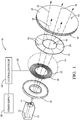
- FIG. 1 is an exploded perspective view illustrating the heating device 10, hereafter referred to as the device 10.
- the device 10 includes a housing 12 configured to retain a camera lens 14.
- the housing 12 may be formed of any material, such as a polymeric material, a ceramic, or a metal.
- the housing 12 may have a circular cross section or may have any other cross section, such as a rectilinear cross section.
- the housing 12 may include an imager 15 used to render an image of a surrounding area.
- the camera lens 14 defines a field-of-view 16 and an optical axis 18 as illustrated in figure 1 .
- the housing 12 may be mounted on a front of a vehicle, on sides of a vehicle, on a rear of a vehicle, or mounted in the interior of the vehicle at a location suitable for the camera to view the area around the vehicle through the windshield 20. In the examples illustrated herein, the housing 12 is mounted inside the vehicle with the view through the windshield 20.
- the device 10 also includes a primary induction coil 22 positioned proximate the housing 12 and configured to generate a magnetic field 24 in response to receiving electrical power 26 from a power supply 28.
- the power supply 28 may be a direct-current (DC) power supply 28, or may be an alternating-current (AC) power supply 28. In the examples illustrated herein the power supply 28 is an AC power supply 28.
- the primary induction coil 22 surrounds the optical axis 18 of the camera lens 14 and may also surround a portion of the housing 12.
- a number of windings 30 (e.g., wires, conductive traces, etc.) on the primary induction coil 22 is at least one and are preferably wound onto a ferromagnetic core 32 (e.g. iron, ferrites, etc.).
- a single winding 30 (i.e. a single wire) of the primary induction coil 22 may be any diameter, and in the examples illustrated herein, preferably has the diameter in a range from 0.2mm to 1.0mm.
- the windings 30 may be formed of any electrically conductive material, such as copper alloys or aluminum alloys and may include a dielectric layer on a surface of the windings 30.
- the device 10 also includes a controller circuit 34 in electrical contact with the primary induction coil 22.
- the power supply 28 may be separate or integral to the controller circuit 34, and in the examples illustrated herein, the power supply 28 is integral to the controller circuit 34.
- the controller circuit 34 is configured to control the electrical power 26 delivered to the primary induction coil 22.
- the controller circuit 34 may include a processor (not shown) such as a microprocessor or other control circuitry such as analog and/or digital control circuitry including an application specific integrated circuit (ASIC) for processing data as should be evident to those in the art.
- the controller circuit 34 may include a memory (not shown), including non-volatile memory, such as electrically erasable programmable read-only memory (EEPROM) for storing one or more routines, thresholds, and captured data.
- the one or more routines may be executed by the processor to perform steps for determining the electrical power 26 delivered to the primary induction coil 22 based on signals received by the controller circuit 34 from the primary induction coil 22, as described herein.
- the device 10 also includes a secondary induction coil 36 overlaying the primary induction coil 22.
- the secondary induction coil 36 is configured to receive the magnetic field 24 from the primary induction coil 22, thereby generating heat 38.
- the magnetic field 24 from the primary induction coil 22 induces an electrical current in the secondary induction coil 36.
- the induced electrical current in the secondary induction coil 36 causes the secondary induction coil 36 to increase in temperature because the secondary induction coil 36 is formed of a material that has an electrical resistance.
- the electrical resistance of the secondary induction coil 36 resists the flow of electrical current within the secondary induction coil 36, which generates the heat 38 (also known as Joule heating or Ohmic heating). It will be appreciated that no wire connections exist between the primary induction coil 22 and the secondary induction coil 36.
- the secondary induction coil 36 also surrounds the optical axis 18 and is in direct contact with the windshield 20 of the vehicle.
- the secondary induction coil 36 is located on an inner surface 42 of the windshield 20.
- the secondary induction coil 36 may be located on an outer surface 43 of the windshield 20.
- the secondary induction coil 36 defines a viewing window 40 through which the camera lens 14 views the surrounding area. That is, an inner diameter of the secondary induction coil 36, as illustrated in figure 1 , creates a "window" through which light rays may pass to the camera lens 14 and imager 15.
- the secondary induction coil 36 heats the viewing window 40 and removes condensation (e.g., fog, ice, etc.) when the primary induction coil 22 receives the electrical power 26 from the controller circuit 34.
- a heating rate and a maximum temperature is controlled to inhibit a thermal shock to the windshield 20, and also to prevent an unsafe surface temperature of the windshield 20 for human contact.
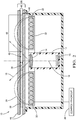
- Figure 2 is a section view of the device 10 and illustrates an embodiment where the secondary induction coil 36 is located between glass layers 44 of the windshield 20.
- a distance 46 between the primary induction coil 22 and the secondary induction coil 36 is preferably in a range from 0.0mm to about 10.0mm. The distance 46 primarily impacts a coupling of the primary induction coil 22 and the secondary induction coil 36.
- the number of windings 30 on the secondary induction coil 36 is at least one, and may be increased to achieve a specific temperature profile applied to the windshield 20.
- the windings 30 on the secondary induction coil 36 may be a single flat winding 30 that may be deposited using a thick-film ink, for example.
- the secondary induction coil 36 as illustrated in figure 2 has a thickness 48 in the range from about 1 ⁇ m to about 1000 ⁇ m. The thickness 48 may be adjusted based on the type of material comprising the secondary induction coil 36, and based on a frequency 50 of the electrical power 26 delivered to the primary induction coil 22.
- the secondary induction coil 36 has a thickness 48 of 400 ⁇ m and is formed of a material with a low relative magnetic permeability (e.g., silver, aluminum, etc.). In another embodiment, the secondary induction coil 36 is formed of a material having higher relative magnetic permeability (e.g., iron) having a thickness 48 of 15 ⁇ m. The thickness 48 may also be reduced by increasing the frequency 50 of the of the electrical power 26 delivered to the primary induction coil 22.
- the secondary induction coil 36 has a width 49 in a range from about 0.1mm to 10mm, and preferably has the width 49 of about 5mm due to packaging constraints on the windshield 20. It will be appreciated that the width 49 of the secondary induction coil 36 affects the heat transfer to the windshield 20. The width 49 may be user defined depending on a desired heating profile for the windshield 20.
- FIG 3 is a magnified view of a portion of the device 10 of figure 1 .
- the secondary induction coil 36 is preferably comprised of a first layer 52 of resistive material that dissipates the power transmitted by the magnetic field 24, and a second layer 54 of low-Curie point ferrite.
- a Curie point temperature e.g. approximately 90 degrees Celsius for a Mn-Zn ferrite at 8 ⁇ m-9 ⁇ m thickness 48
- the magnetic permeability of the second layer 54 is decreased, thereby reducing the induced heating of the secondary induction coil 36.
- This reduction of the induced heating of the secondary induction coil 36 changes a resonant-frequency of a control circuit 56, the benefit of which will be described in more detail below.
- the secondary induction coil 36 is formed of a conductive material having a greater electrical resistance than that of the primary induction coil 22.
- the first layer 52 and the second layer 54 may also have a protective coating (not specifically shown) applied to their exposed surfaces to improve a durability of the layers.
- the secondary induction coil 36 may be characterized as segmented 58, wherein adjoining segments 58 are formed of materials having a different electrical conductivity from one another. That is, a first segment may have a relatively low electrical resistance thereby emitting a relatively low quantity of heat 38, wherein a second segment in contact with the first segment may have a higher electrical resistance compared to the first segment, thereby emitting a larger quantity of heat 38 than the first segment.
- This segmentation 58 has the technical benefit of enabling a specific heating profile on the windshield 20.
- FIG. 4 is a schematic diagram of the device 10 illustrating the controller circuit 34.
- the controller circuit 34 preferably includes a low-Q resonant control circuit 56 in electrical communication with the primary induction coil 22.
- a Q-factor (i.e., quality factor) of an electronic circuit is a parameter that describes the resonance behavior of a harmonic oscillator or resonator.
- the low-Q factor is indicative of an overdamped system that does not resonate or oscillate.
- the low-Q resonant control circuit 56 has the technical benefit of improved temperature control in the secondary induction coil 36. It will be appreciated that the values of capacitors C1 and C2 (not specifically shown) may be selected to achieve the desired resonant-frequency to drive the secondary induction coil 36 and produce the desired heat 38.
- the temperature of the secondary induction coil 36 may be controlled by adjusting a voltage 62 applied to, and/or adjusting the frequency 50 of a signal delivered to, the primary induction coil 22 through the MOSFETs M1 and M2 (not specifically shown) and through the power supply 28.
- the controller circuit 34 is configured to monitor an impedance of the primary induction coil 22, which is directly related to the temperature of the secondary induction coil 36, and controls the voltage 62 and/or frequency 50 (e.g. 40kHz) to maintain proper operation of the control circuit 56. This method of temperature measurement has the technical benefit or eliminating a separate temperature sensor mounted to the windshield 20.
Landscapes
- Physics & Mathematics (AREA)
- Electromagnetism (AREA)
- Engineering & Computer Science (AREA)
- Mechanical Engineering (AREA)
- Aviation & Aerospace Engineering (AREA)
- General Physics & Mathematics (AREA)
- General Induction Heating (AREA)
Claims (15)
- Windschutzscheibe (20) oder Abdeckscheibe mit einer Heizvorrichtung (10), wobei die Heizvorrichtung (10) umfasst:ein Gehäuse (12), das ein Kameraobjektiv (14) aufnimmt;eine primäre Induktionsspule (22), die in der Nähe des Gehäuses (12) positioniert und so konfiguriert ist, dass sie ein Magnetfeld (24) als Reaktion auf den Empfang von elektrischer Leistung (26) von einer Stromversorgung (28) erzeugt;eine Steuerungsschaltung (34), die in elektrischem Kontakt mit der primären Induktionsspule (22) steht und so konfiguriert ist, dass sie die der primären Induktionsspule (22) zugeführte elektrische Leistung (26) steuert; undeine sekundäre Induktionsspule (36), die die primäre Induktionsspule (22) überlagert und so konfiguriert ist, dass sie das Magnetfeld (24) von der primären Induktionsspule (22) empfängt und Wärme (38) erzeugt;dadurch gekennzeichnet, dassdie sekundäre Induktionsspule (36) in direktem Kontakt mit der Windschutzscheibe (20) oder der Abdeckscheibe steht und ein Sichtfenster (40) definiert, durch welches hindurch das Kameraobjektiv (14) einen umgebenden Bereich betrachtet;wobei die sekundäre Induktionsspule (36) das Sichtfenster (40) erwärmt, wenn die primäre Induktionsspule (22) die elektrische Leistung (26) empfängt.
- Windschutzscheibe (20) oder Abdeckscheibe nach Anspruch 1, wobei die primäre Induktionsspule (22) eine optische Achse (18) des Kameraobjektivs (14) umgibt.
- Windschutzscheibe (20) oder Abdeckscheibe nach einem der vorhergehenden Ansprüche, wobei die Steuerungsschaltung (34) einen Resonanzkreis mit geringer Güte in elektrischer Verbindung mit der primären Induktionsspule (22) enthält.
- Windschutzscheibe (20) oder Abdeckscheibe nach einem der vorhergehenden Ansprüche, wobei eine Temperatur der sekundären Induktionsspule (36) durch Einstellen einer an die primäre Induktionsspule (22) angelegten Spannung (62) gesteuert wird.
- Windschutzscheibe (20) oder Abdeckscheibe nach einem der vorhergehenden Ansprüche, wobei eine Temperatur der sekundären Induktionsspule (36) durch Einstellen einer Frequenz (50) eines an die primäre Induktionsspule (22) gelieferten Signals gesteuert wird.
- Windschutzscheibe (20) oder Abdeckscheibe nach einem der vorhergehenden Ansprüche, wobei die sekundäre Induktionsspule (36) aus einer ersten Schicht (52) aus Widerstandsmaterial und einer zweiten Schicht (54) aus Ferrit mit niedrigem Curiepunkt besteht.
- Windschutzscheibe (20) oder Abdeckscheibe nach einem der vorhergehenden Ansprüche, wobei die sekundäre Induktionsspule (36) zwischen Glasschichten (44) der Windschutzscheibe (20) angeordnet ist.
- Windschutzscheibe (20) oder Abdeckscheibe nach einem der vorhergehenden Ansprüche, wobei die sekundäre Induktionsspule (36) an einer Innenfläche (42) der Windschutzscheibe (20) angeordnet ist.
- Windschutzscheibe (20) oder Abdeckscheibe nach einem der vorhergehenden Ansprüche, wobei die sekundäre Induktionsspule (36) aus einem leitfähigen Material gebildet ist, das einen größeren elektrischen Widerstand als die primäre Induktionsspule (22) aufweist.
- Windschutzscheibe (20) oder Abdeckscheibe nach einem der vorhergehenden Ansprüche, wobei die sekundäre Induktionsspule (36) als segmentiert (58) beschrieben ist, wobei benachbarte Segmente (58) aus Materialien gebildet sind, die eine voneinander verschiedene elektrische Leitfähigkeit aufweisen.
- Windschutzscheibe (20) oder Abdeckscheibe nach einem der vorhergehenden Ansprüche, wobei ein Abstand (46) zwischen der primären Induktionsspule (22) und der sekundären Induktionsspule (36) in einem Bereich von 0,0 mm bis 10,0 mm liegt.
- Windschutzscheibe (20) oder Abdeckscheibe nach einem der vorhergehenden Ansprüche, wobei eine Anzahl von Wicklungen (30) an der primären Induktionsspule (22) mindestens eins ist, oder
eine Anzahl von Wicklungen (30) an der sekundären Induktionsspule (36) mindestens eins ist. - Windschutzscheibe (20) oder Abdeckscheibe nach einem der vorhergehenden Ansprüche, wobei die sekundäre Induktionsspule (36) eine Dicke (48) in einem Bereich von 1 µm bis 1000 µm aufweist.
- Windschutzscheibe (20) oder Abdeckscheibe nach einem der vorhergehenden Ansprüche, wobei die sekundäre Induktionsspule (36) eine Breite (49) in einem Bereich von 0,1 mm bis 10 mm aufweist.
- Verwendung einer Heizvorrichtung (10), wobei die Heizvorrichtung (10) umfasst:ein Gehäuse (12), das ein Kameraobjektiv (14) aufnimmt;eine primäre Induktionsspule (22), die in der Nähe des Gehäuses (12) positioniert und so konfiguriert ist, dass sie ein Magnetfeld (24) als Reaktion auf den Empfang von elektrischer Leistung (26) von einer Stromversorgung (28) erzeugt;eine Steuerungsschaltung (34), die in elektrischem Kontakt mit der primären Induktionsspule (22) steht und so konfiguriert ist, dass sie die der primären Induktionsspule (22) zugeführte elektrische Leistung (26) steuert; undeine sekundäre Induktionsspule (36), die die primäre Induktionsspule (22) überlagert und so konfiguriert ist, dass sie das Magnetfeld (24) von der primären Induktionsspule (22) empfängt und Wärme (38) erzeugt;wobeidie sekundäre Induktionsspule (36) in direktem Kontakt mit einer Windschutzscheibe (20) eines Fahrzeugs oder einer Abdeckscheibe steht und ein Sichtfenster (40) definiert, durch welches hindurch das Kameraobjektiv (14) einen umgebenden Bereich betrachtet;wobei die sekundäre Induktionsspule (36) das Sichtfenster (40) erwärmt, wenn die primäre Induktionsspule (22) die elektrische Leistung (26) empfängt.
Priority Applications (4)
| Application Number | Priority Date | Filing Date | Title |
|---|---|---|---|
| EP18213507.9A EP3672361B1 (de) | 2018-12-18 | 2018-12-18 | Heizvorrichtung |
| US16/713,063 US11654864B2 (en) | 2018-12-18 | 2019-12-13 | Heating device |
| CN201911280305.1A CN111343739B (zh) | 2018-12-18 | 2019-12-13 | 加热装置 |
| US18/298,986 US12534047B2 (en) | 2018-12-18 | 2023-04-11 | Heating device |
Applications Claiming Priority (1)
| Application Number | Priority Date | Filing Date | Title |
|---|---|---|---|
| EP18213507.9A EP3672361B1 (de) | 2018-12-18 | 2018-12-18 | Heizvorrichtung |
Publications (2)
| Publication Number | Publication Date |
|---|---|
| EP3672361A1 EP3672361A1 (de) | 2020-06-24 |
| EP3672361B1 true EP3672361B1 (de) | 2021-07-07 |
Family
ID=64744678
Family Applications (1)
| Application Number | Title | Priority Date | Filing Date |
|---|---|---|---|
| EP18213507.9A Active EP3672361B1 (de) | 2018-12-18 | 2018-12-18 | Heizvorrichtung |
Country Status (3)
| Country | Link |
|---|---|
| US (2) | US11654864B2 (de) |
| EP (1) | EP3672361B1 (de) |
| CN (1) | CN111343739B (de) |
Families Citing this family (5)
| Publication number | Priority date | Publication date | Assignee | Title |
|---|---|---|---|---|
| EP3672361B1 (de) | 2018-12-18 | 2021-07-07 | Aptiv Technologies Limited | Heizvorrichtung |
| EP3672362B2 (de) | 2018-12-18 | 2024-01-17 | Aptiv Technologies Limited | Heizvorrichtung |
| CN114599541A (zh) * | 2019-11-11 | 2022-06-07 | 沃尔沃卡车集团 | 用于车辆的压电能量收集系统 |
| US12238845B2 (en) * | 2020-12-01 | 2025-02-25 | Ford Global Technologies, Llc | Systems and methods for heating windshield camera viewing zones |
| CN116781999A (zh) * | 2022-03-08 | 2023-09-19 | 佛吉亚歌乐电子(厦门)有限公司 | 一种摄像头组件、车载系统以及车辆 |
Citations (8)
| Publication number | Priority date | Publication date | Assignee | Title |
|---|---|---|---|---|
| US20060171704A1 (en) | 2002-11-14 | 2006-08-03 | Bingle Robert L | Imaging system for vehicle |
| US20080034528A1 (en) | 2006-08-09 | 2008-02-14 | Thermal Solutions, Inc. | Inductively heated windshield wiper assembly |
| US20100078427A1 (en) | 2007-01-23 | 2010-04-01 | Mgs - Ag Modular Galley Systems | Device for converting inductively transmitted electric power, and method for the production of such a device |
| EP3001674A1 (de) | 2014-09-26 | 2016-03-30 | Delphi Technologies, Inc. | Fahrzeugbildgeberanordnung mit lokalisierter fensterklarung |
| WO2018015856A2 (en) | 2016-07-18 | 2018-01-25 | E-Wenco S.R.L. | Heating device, its use and kit |
| US20180170314A1 (en) | 2016-12-20 | 2018-06-21 | Magna Exteriors Gmbh | Synthetic Component with Sensor |
| US20180210161A1 (en) | 2015-07-09 | 2018-07-26 | Lg Innotek Co., Ltd. | Camera module |
| WO2018184892A1 (en) | 2017-04-07 | 2018-10-11 | Electrolux Appliances Aktiebolag | Optical system and induction hob comprising an optical system |
Family Cites Families (34)
| Publication number | Priority date | Publication date | Assignee | Title |
|---|---|---|---|---|
| GB835161A (en) | 1956-11-16 | 1960-05-18 | Optische Ind De Oude Delft Nv | Improvements relating to methods of heating aerial cameras and aerial cameras heatedin accordance with said methods |
| US3058840A (en) * | 1959-04-16 | 1962-10-16 | Electric Furnace Co | Induction strip heating apparatus |
| US3250636A (en) * | 1963-01-02 | 1966-05-10 | Xerox Corp | Method and apparatus for image reproduction with the use of a reusable heat demagnetizable ferromagnetic imaging layer |
| US20060035051A1 (en) * | 2000-06-23 | 2006-02-16 | Jean-Benoit Lhoest | Glazing |
| DE102004015004A1 (de) * | 2004-03-26 | 2005-10-13 | Enocean Gmbh | Anordnung mit zumindest einer elektrischen Spannungsquelle und einer ersten Spannungswandlerschaltung |
| DE102004057322B4 (de) | 2004-11-27 | 2021-01-28 | Volkswagen Ag | Anordnung einer Kamera hinter einer Fahrzeugverglasung und Kraftfahrzeug |
| US7279664B2 (en) * | 2005-07-26 | 2007-10-09 | Boston Scientific Scimed, Inc. | Resonator for medical device |
| CN101553765A (zh) | 2006-08-09 | 2009-10-07 | 热溶体股份有限公司 | 感应式加热挡风玻璃刮拭组件 |
| FR2917939B1 (fr) | 2007-06-22 | 2009-09-04 | Airbus France Sas | Systeme de degivrage ou de desembuage d'un instrument optique et dispositif d'acquisition d'images equipe d'un tel systeme. |
| DE102008031924B4 (de) | 2008-07-08 | 2019-06-13 | Olympus Winter & Ibe Gmbh | Endoskop mit Widerstandsheizung |
| CN102187273B (zh) * | 2008-10-14 | 2014-03-26 | 日本电产三协株式会社 | 带抖动修正功能的光学单元、光学设备及带抖动修正功能的光学单元的制造方法 |
| WO2012129521A1 (en) * | 2011-03-23 | 2012-09-27 | Gentex Corporation | Lens cleaning apparatus |
| US9642192B2 (en) * | 2011-08-04 | 2017-05-02 | Fuelcell Energy, Inc. | Method and manufacturing assembly for sintering fuel cell electrodes and impregnating porous electrodes with electrolyte powders by induction heating for mass production |
| JPWO2013038694A1 (ja) * | 2011-09-14 | 2015-03-23 | パナソニックIpマネジメント株式会社 | 非接触受電装置および非接触電力伝送装置 |
| US9820339B2 (en) * | 2011-09-29 | 2017-11-14 | The Boeing Company | Induction heating using induction coils in series-parallel circuits |
| US20140158680A1 (en) * | 2011-12-20 | 2014-06-12 | Panasonic Corporation | Contactless power feeder and contactless transmission system |
| CN102736369B (zh) | 2012-06-28 | 2014-12-10 | 浙江宇视科技有限公司 | 一种摄像机加热系统 |
| CN102789115B (zh) | 2012-08-23 | 2015-09-09 | 浙江宇视科技有限公司 | 一种摄像机除雾系统 |
| DE102013020894B3 (de) * | 2013-12-11 | 2015-04-09 | Mekra Lang Gmbh & Co. Kg | Kamera mit Heizelement |
| JP6329410B2 (ja) | 2014-03-20 | 2018-05-23 | 惠州市大亜湾永昶電子工業有限公司 | レンズ駆動装置 |
| KR20150124197A (ko) | 2014-04-28 | 2015-11-05 | 삼성전기주식회사 | 카메라 모듈 |
| CN104618630A (zh) | 2014-12-25 | 2015-05-13 | 贵州黔程天力智能科技有限公司 | 一种具有除雾功能的摄像头 |
| US10921168B2 (en) * | 2015-09-11 | 2021-02-16 | Wuhan Tailimeixin Healthcare Technologies Co., Ltd. | Integrated measuring system and method |
| DE102016103270B3 (de) * | 2016-02-24 | 2017-05-11 | Ev Group E. Thallner Gmbh | Vorrichtung und Verfahren zur Halterung, Rotation sowie Heizung und/oder Kühlung eines Substrats |
| JP6573713B2 (ja) * | 2016-03-23 | 2019-09-11 | 日立オートモティブシステムズ株式会社 | 車載画像処理装置 |
| CN205901891U (zh) | 2016-07-05 | 2017-01-18 | 广州市维视电子有限公司 | 一种车载翻盖摄像机 |
| CN206096730U (zh) | 2016-10-10 | 2017-04-12 | 福州鑫图光电有限公司 | 一种带窗片加热功能的制冷相机 |
| EP3373571A1 (de) | 2017-03-06 | 2018-09-12 | SMR Patents S.à.r.l. | Erwärmungsvorrichtung für eine kameralinse |
| CN207416705U (zh) | 2017-11-09 | 2018-05-29 | 成都鼎熙瑞泽科技有限公司 | 一种电磁感应加热后视镜 |
| CN107942502B (zh) | 2017-12-15 | 2024-03-01 | 中国科学院国家天文台南京天文光学技术研究所 | 低温环境下天文望远镜镜面的除霜雪装置及其工作方法 |
| CN208175020U (zh) | 2018-04-02 | 2018-11-30 | 镇江市天祥精密机电有限公司 | 一种便于拆装的后视镜用感应加热装置 |
| CN108803201A (zh) | 2018-06-15 | 2018-11-13 | 济南每日优鲜便利购网络科技有限公司 | 用于制冷设备的摄像头组件除雾方法 |
| EP3672362B2 (de) * | 2018-12-18 | 2024-01-17 | Aptiv Technologies Limited | Heizvorrichtung |
| EP3672361B1 (de) | 2018-12-18 | 2021-07-07 | Aptiv Technologies Limited | Heizvorrichtung |
-
2018
- 2018-12-18 EP EP18213507.9A patent/EP3672361B1/de active Active
-
2019
- 2019-12-13 CN CN201911280305.1A patent/CN111343739B/zh active Active
- 2019-12-13 US US16/713,063 patent/US11654864B2/en active Active
-
2023
- 2023-04-11 US US18/298,986 patent/US12534047B2/en active Active
Patent Citations (8)
| Publication number | Priority date | Publication date | Assignee | Title |
|---|---|---|---|---|
| US20060171704A1 (en) | 2002-11-14 | 2006-08-03 | Bingle Robert L | Imaging system for vehicle |
| US20080034528A1 (en) | 2006-08-09 | 2008-02-14 | Thermal Solutions, Inc. | Inductively heated windshield wiper assembly |
| US20100078427A1 (en) | 2007-01-23 | 2010-04-01 | Mgs - Ag Modular Galley Systems | Device for converting inductively transmitted electric power, and method for the production of such a device |
| EP3001674A1 (de) | 2014-09-26 | 2016-03-30 | Delphi Technologies, Inc. | Fahrzeugbildgeberanordnung mit lokalisierter fensterklarung |
| US20180210161A1 (en) | 2015-07-09 | 2018-07-26 | Lg Innotek Co., Ltd. | Camera module |
| WO2018015856A2 (en) | 2016-07-18 | 2018-01-25 | E-Wenco S.R.L. | Heating device, its use and kit |
| US20180170314A1 (en) | 2016-12-20 | 2018-06-21 | Magna Exteriors Gmbh | Synthetic Component with Sensor |
| WO2018184892A1 (en) | 2017-04-07 | 2018-10-11 | Electrolux Appliances Aktiebolag | Optical system and induction hob comprising an optical system |
Also Published As
| Publication number | Publication date |
|---|---|
| US11654864B2 (en) | 2023-05-23 |
| CN111343739A (zh) | 2020-06-26 |
| US20200189523A1 (en) | 2020-06-18 |
| US12534047B2 (en) | 2026-01-27 |
| US20230242077A1 (en) | 2023-08-03 |
| EP3672361A1 (de) | 2020-06-24 |
| CN111343739B (zh) | 2022-03-18 |
Similar Documents
| Publication | Publication Date | Title |
|---|---|---|
| US12534047B2 (en) | Heating device | |
| US12085711B2 (en) | Heating device | |
| US12580430B2 (en) | Systems and methods for wireless power and data transfer utilizing multiple antenna receivers | |
| US20180210161A1 (en) | Camera module | |
| CN110168412B (zh) | 利用热敏材料和电感式感测进行外部物体检测 | |
| EP2040202B1 (de) | Antennenspule zur anbringung auf substrat und antennenvorrichtung | |
| US20120176215A1 (en) | Coil Component | |
| JP5533136B2 (ja) | アンテナ装置 | |
| CN115004564A (zh) | 用于包括脉宽编码数据通信的无线功率传递的系统和方法 | |
| US6850728B2 (en) | Induction heating roller apparatus, fixing apparatus and image formation apparatus | |
| EP1944878A1 (de) | Rfid-etikett mit elektromagnetischer induktion und zugangseinheit | |
| JPWO2016067528A1 (ja) | 電池内蔵機器 | |
| JP6672886B2 (ja) | ループアンテナ及び無線タグ | |
| DE202018006845U1 (de) | Heizvorrichtung | |
| CN220174498U (zh) | 一种温度传感单元、电磁加热组件及电子雾化装置 | |
| RU2847752C2 (ru) | Мобильный терминал связи, содержащий генератор аэрозоля, и способ управления таким терминалом | |
| RU2846635C2 (ru) | Мобильный терминал связи, содержащий генератор аэрозоля, и способ управления таким терминалом | |
| KR102939117B1 (ko) | 에어로졸생성부를 포함하는 이동 통신 단말기 | |
| CN117941884A (zh) | 一种温度传感单元、电磁加热组件及电子雾化装置 | |
| JP2010021617A (ja) | 電磁波出力回路及び無線タグ用通信装置 | |
| KR20050120448A (ko) | 침구류용 무자계무전계 발열선 | |
| CN120112186A (zh) | 气溶胶生成装置、包括气溶胶生成装置的气溶胶生成系统以及对气溶胶生成装置进行制造的方法 | |
| JP5732909B2 (ja) | 赤外線センサ装置およびこれを備えた誘導加熱調理器 | |
| JP2004363638A (ja) | 車両用アンテナ装置及びこれを用いた通信システム |
Legal Events
| Date | Code | Title | Description |
|---|---|---|---|
| PUAI | Public reference made under article 153(3) epc to a published international application that has entered the european phase |
Free format text: ORIGINAL CODE: 0009012 |
|
| STAA | Information on the status of an ep patent application or granted ep patent |
Free format text: STATUS: THE APPLICATION HAS BEEN PUBLISHED |
|
| AK | Designated contracting states |
Kind code of ref document: A1 Designated state(s): AL AT BE BG CH CY CZ DE DK EE ES FI FR GB GR HR HU IE IS IT LI LT LU LV MC MK MT NL NO PL PT RO RS SE SI SK SM TR |
|
| AX | Request for extension of the european patent |
Extension state: BA ME |
|
| STAA | Information on the status of an ep patent application or granted ep patent |
Free format text: STATUS: REQUEST FOR EXAMINATION WAS MADE |
|
| 17P | Request for examination filed |
Effective date: 20201218 |
|
| RBV | Designated contracting states (corrected) |
Designated state(s): AL AT BE BG CH CY CZ DE DK EE ES FI FR GB GR HR HU IE IS IT LI LT LU LV MC MK MT NL NO PL PT RO RS SE SI SK SM TR |
|
| GRAP | Despatch of communication of intention to grant a patent |
Free format text: ORIGINAL CODE: EPIDOSNIGR1 |
|
| STAA | Information on the status of an ep patent application or granted ep patent |
Free format text: STATUS: GRANT OF PATENT IS INTENDED |
|
| INTG | Intention to grant announced |
Effective date: 20210129 |
|
| RIC1 | Information provided on ipc code assigned before grant |
Ipc: H05B 6/10 20060101AFI20210115BHEP |
|
| GRAS | Grant fee paid |
Free format text: ORIGINAL CODE: EPIDOSNIGR3 |
|
| GRAA | (expected) grant |
Free format text: ORIGINAL CODE: 0009210 |
|
| STAA | Information on the status of an ep patent application or granted ep patent |
Free format text: STATUS: THE PATENT HAS BEEN GRANTED |
|
| AK | Designated contracting states |
Kind code of ref document: B1 Designated state(s): AL AT BE BG CH CY CZ DE DK EE ES FI FR GB GR HR HU IE IS IT LI LT LU LV MC MK MT NL NO PL PT RO RS SE SI SK SM TR |
|
| REG | Reference to a national code |
Ref country code: GB Ref legal event code: FG4D |
|
| REG | Reference to a national code |
Ref country code: AT Ref legal event code: REF Ref document number: 1409895 Country of ref document: AT Kind code of ref document: T Effective date: 20210715 |
|
| REG | Reference to a national code |
Ref country code: DE Ref legal event code: R096 Ref document number: 602018019638 Country of ref document: DE |
|
| REG | Reference to a national code |
Ref country code: IE Ref legal event code: FG4D |
|
| REG | Reference to a national code |
Ref country code: LT Ref legal event code: MG9D |
|
| REG | Reference to a national code |
Ref country code: NL Ref legal event code: MP Effective date: 20210707 |
|
| REG | Reference to a national code |
Ref country code: AT Ref legal event code: MK05 Ref document number: 1409895 Country of ref document: AT Kind code of ref document: T Effective date: 20210707 |
|
| PG25 | Lapsed in a contracting state [announced via postgrant information from national office to epo] |
Ref country code: SE Free format text: LAPSE BECAUSE OF FAILURE TO SUBMIT A TRANSLATION OF THE DESCRIPTION OR TO PAY THE FEE WITHIN THE PRESCRIBED TIME-LIMIT Effective date: 20210707 Ref country code: RS Free format text: LAPSE BECAUSE OF FAILURE TO SUBMIT A TRANSLATION OF THE DESCRIPTION OR TO PAY THE FEE WITHIN THE PRESCRIBED TIME-LIMIT Effective date: 20210707 Ref country code: HR Free format text: LAPSE BECAUSE OF FAILURE TO SUBMIT A TRANSLATION OF THE DESCRIPTION OR TO PAY THE FEE WITHIN THE PRESCRIBED TIME-LIMIT Effective date: 20210707 Ref country code: ES Free format text: LAPSE BECAUSE OF FAILURE TO SUBMIT A TRANSLATION OF THE DESCRIPTION OR TO PAY THE FEE WITHIN THE PRESCRIBED TIME-LIMIT Effective date: 20210707 Ref country code: FI Free format text: LAPSE BECAUSE OF FAILURE TO SUBMIT A TRANSLATION OF THE DESCRIPTION OR TO PAY THE FEE WITHIN THE PRESCRIBED TIME-LIMIT Effective date: 20210707 Ref country code: NO Free format text: LAPSE BECAUSE OF FAILURE TO SUBMIT A TRANSLATION OF THE DESCRIPTION OR TO PAY THE FEE WITHIN THE PRESCRIBED TIME-LIMIT Effective date: 20211007 Ref country code: PT Free format text: LAPSE BECAUSE OF FAILURE TO SUBMIT A TRANSLATION OF THE DESCRIPTION OR TO PAY THE FEE WITHIN THE PRESCRIBED TIME-LIMIT Effective date: 20211108 Ref country code: NL Free format text: LAPSE BECAUSE OF FAILURE TO SUBMIT A TRANSLATION OF THE DESCRIPTION OR TO PAY THE FEE WITHIN THE PRESCRIBED TIME-LIMIT Effective date: 20210707 Ref country code: AT Free format text: LAPSE BECAUSE OF FAILURE TO SUBMIT A TRANSLATION OF THE DESCRIPTION OR TO PAY THE FEE WITHIN THE PRESCRIBED TIME-LIMIT Effective date: 20210707 Ref country code: BG Free format text: LAPSE BECAUSE OF FAILURE TO SUBMIT A TRANSLATION OF THE DESCRIPTION OR TO PAY THE FEE WITHIN THE PRESCRIBED TIME-LIMIT Effective date: 20211007 Ref country code: LT Free format text: LAPSE BECAUSE OF FAILURE TO SUBMIT A TRANSLATION OF THE DESCRIPTION OR TO PAY THE FEE WITHIN THE PRESCRIBED TIME-LIMIT Effective date: 20210707 |
|
| PG25 | Lapsed in a contracting state [announced via postgrant information from national office to epo] |
Ref country code: PL Free format text: LAPSE BECAUSE OF FAILURE TO SUBMIT A TRANSLATION OF THE DESCRIPTION OR TO PAY THE FEE WITHIN THE PRESCRIBED TIME-LIMIT Effective date: 20210707 Ref country code: LV Free format text: LAPSE BECAUSE OF FAILURE TO SUBMIT A TRANSLATION OF THE DESCRIPTION OR TO PAY THE FEE WITHIN THE PRESCRIBED TIME-LIMIT Effective date: 20210707 Ref country code: GR Free format text: LAPSE BECAUSE OF FAILURE TO SUBMIT A TRANSLATION OF THE DESCRIPTION OR TO PAY THE FEE WITHIN THE PRESCRIBED TIME-LIMIT Effective date: 20211008 |
|
| REG | Reference to a national code |
Ref country code: DE Ref legal event code: R026 Ref document number: 602018019638 Country of ref document: DE |
|
| PLBI | Opposition filed |
Free format text: ORIGINAL CODE: 0009260 |
|
| PLAX | Notice of opposition and request to file observation + time limit sent |
Free format text: ORIGINAL CODE: EPIDOSNOBS2 |
|
| PG25 | Lapsed in a contracting state [announced via postgrant information from national office to epo] |
Ref country code: DK Free format text: LAPSE BECAUSE OF FAILURE TO SUBMIT A TRANSLATION OF THE DESCRIPTION OR TO PAY THE FEE WITHIN THE PRESCRIBED TIME-LIMIT Effective date: 20210707 |
|
| 26 | Opposition filed |
Opponent name: VALEO SYSTEMES D'ESSUYAGE Effective date: 20220407 |
|
| PG25 | Lapsed in a contracting state [announced via postgrant information from national office to epo] |
Ref country code: SM Free format text: LAPSE BECAUSE OF FAILURE TO SUBMIT A TRANSLATION OF THE DESCRIPTION OR TO PAY THE FEE WITHIN THE PRESCRIBED TIME-LIMIT Effective date: 20210707 Ref country code: SK Free format text: LAPSE BECAUSE OF FAILURE TO SUBMIT A TRANSLATION OF THE DESCRIPTION OR TO PAY THE FEE WITHIN THE PRESCRIBED TIME-LIMIT Effective date: 20210707 Ref country code: RO Free format text: LAPSE BECAUSE OF FAILURE TO SUBMIT A TRANSLATION OF THE DESCRIPTION OR TO PAY THE FEE WITHIN THE PRESCRIBED TIME-LIMIT Effective date: 20210707 Ref country code: EE Free format text: LAPSE BECAUSE OF FAILURE TO SUBMIT A TRANSLATION OF THE DESCRIPTION OR TO PAY THE FEE WITHIN THE PRESCRIBED TIME-LIMIT Effective date: 20210707 Ref country code: CZ Free format text: LAPSE BECAUSE OF FAILURE TO SUBMIT A TRANSLATION OF THE DESCRIPTION OR TO PAY THE FEE WITHIN THE PRESCRIBED TIME-LIMIT Effective date: 20210707 Ref country code: AL Free format text: LAPSE BECAUSE OF FAILURE TO SUBMIT A TRANSLATION OF THE DESCRIPTION OR TO PAY THE FEE WITHIN THE PRESCRIBED TIME-LIMIT Effective date: 20210707 |
|
| PG25 | Lapsed in a contracting state [announced via postgrant information from national office to epo] |
Ref country code: MC Free format text: LAPSE BECAUSE OF FAILURE TO SUBMIT A TRANSLATION OF THE DESCRIPTION OR TO PAY THE FEE WITHIN THE PRESCRIBED TIME-LIMIT Effective date: 20210707 Ref country code: IT Free format text: LAPSE BECAUSE OF FAILURE TO SUBMIT A TRANSLATION OF THE DESCRIPTION OR TO PAY THE FEE WITHIN THE PRESCRIBED TIME-LIMIT Effective date: 20210707 |
|
| REG | Reference to a national code |
Ref country code: CH Ref legal event code: PL |
|
| PLBB | Reply of patent proprietor to notice(s) of opposition received |
Free format text: ORIGINAL CODE: EPIDOSNOBS3 |
|
| REG | Reference to a national code |
Ref country code: BE Ref legal event code: MM Effective date: 20211231 |
|
| PG25 | Lapsed in a contracting state [announced via postgrant information from national office to epo] |
Ref country code: LU Free format text: LAPSE BECAUSE OF NON-PAYMENT OF DUE FEES Effective date: 20211218 Ref country code: IE Free format text: LAPSE BECAUSE OF NON-PAYMENT OF DUE FEES Effective date: 20211218 |
|
| PG25 | Lapsed in a contracting state [announced via postgrant information from national office to epo] |
Ref country code: BE Free format text: LAPSE BECAUSE OF NON-PAYMENT OF DUE FEES Effective date: 20211231 |
|
| PG25 | Lapsed in a contracting state [announced via postgrant information from national office to epo] |
Ref country code: LI Free format text: LAPSE BECAUSE OF NON-PAYMENT OF DUE FEES Effective date: 20211231 Ref country code: CH Free format text: LAPSE BECAUSE OF NON-PAYMENT OF DUE FEES Effective date: 20211231 |
|
| RAP4 | Party data changed (patent owner data changed or rights of a patent transferred) |
Owner name: APTIV TECHNOLOGIES LIMITED |
|
| PG25 | Lapsed in a contracting state [announced via postgrant information from national office to epo] |
Ref country code: CY Free format text: LAPSE BECAUSE OF FAILURE TO SUBMIT A TRANSLATION OF THE DESCRIPTION OR TO PAY THE FEE WITHIN THE PRESCRIBED TIME-LIMIT Effective date: 20210707 |
|
| PG25 | Lapsed in a contracting state [announced via postgrant information from national office to epo] |
Ref country code: HU Free format text: LAPSE BECAUSE OF FAILURE TO SUBMIT A TRANSLATION OF THE DESCRIPTION OR TO PAY THE FEE WITHIN THE PRESCRIBED TIME-LIMIT; INVALID AB INITIO Effective date: 20181218 |
|
| APBM | Appeal reference recorded |
Free format text: ORIGINAL CODE: EPIDOSNREFNO |
|
| APBP | Date of receipt of notice of appeal recorded |
Free format text: ORIGINAL CODE: EPIDOSNNOA2O |
|
| APAH | Appeal reference modified |
Free format text: ORIGINAL CODE: EPIDOSCREFNO |
|
| APBQ | Date of receipt of statement of grounds of appeal recorded |
Free format text: ORIGINAL CODE: EPIDOSNNOA3O |
|
| PG25 | Lapsed in a contracting state [announced via postgrant information from national office to epo] |
Ref country code: MK Free format text: LAPSE BECAUSE OF FAILURE TO SUBMIT A TRANSLATION OF THE DESCRIPTION OR TO PAY THE FEE WITHIN THE PRESCRIBED TIME-LIMIT Effective date: 20210707 |
|
| PG25 | Lapsed in a contracting state [announced via postgrant information from national office to epo] |
Ref country code: TR Free format text: LAPSE BECAUSE OF FAILURE TO SUBMIT A TRANSLATION OF THE DESCRIPTION OR TO PAY THE FEE WITHIN THE PRESCRIBED TIME-LIMIT Effective date: 20210707 |
|
| PG25 | Lapsed in a contracting state [announced via postgrant information from national office to epo] |
Ref country code: MT Free format text: LAPSE BECAUSE OF FAILURE TO SUBMIT A TRANSLATION OF THE DESCRIPTION OR TO PAY THE FEE WITHIN THE PRESCRIBED TIME-LIMIT Effective date: 20210707 |
|
| REG | Reference to a national code |
Ref country code: DE Ref legal event code: R100 Ref document number: 602018019638 Country of ref document: DE |
|
| REG | Reference to a national code |
Ref country code: DE Ref legal event code: R081 Ref document number: 602018019638 Country of ref document: DE Owner name: APTIV TECHNOLOGIES AG, CH Free format text: FORMER OWNER: APTIV TECHNOLOGIES LIMITED, ST. MICHAEL, BB |
|
| APBU | Appeal procedure closed |
Free format text: ORIGINAL CODE: EPIDOSNNOA9O |
|
| PLCK | Communication despatched that opposition was rejected |
Free format text: ORIGINAL CODE: EPIDOSNREJ1 |
|
| STAA | Information on the status of an ep patent application or granted ep patent |
Free format text: STATUS: OPPOSITION REJECTED |
|
| PLBN | Opposition rejected |
Free format text: ORIGINAL CODE: 0009273 |
|
| 27O | Opposition rejected |
Effective date: 20250411 |
|
| PGFP | Annual fee paid to national office [announced via postgrant information from national office to epo] |
Ref country code: DE Payment date: 20251117 Year of fee payment: 8 |
|
| PGFP | Annual fee paid to national office [announced via postgrant information from national office to epo] |
Ref country code: GB Payment date: 20251210 Year of fee payment: 8 |
|
| PGFP | Annual fee paid to national office [announced via postgrant information from national office to epo] |
Ref country code: FR Payment date: 20251202 Year of fee payment: 8 |