EP3672448B1 - Systemes et procedes d'estimation de la pose tridimensionnelle d'un dispositif d'hygiene bucco-dentaire a marqueurs visuels - Google Patents
Systemes et procedes d'estimation de la pose tridimensionnelle d'un dispositif d'hygiene bucco-dentaire a marqueurs visuels Download PDFInfo
- Publication number
- EP3672448B1 EP3672448B1 EP18830615.3A EP18830615A EP3672448B1 EP 3672448 B1 EP3672448 B1 EP 3672448B1 EP 18830615 A EP18830615 A EP 18830615A EP 3672448 B1 EP3672448 B1 EP 3672448B1
- Authority
- EP
- European Patent Office
- Prior art keywords
- visual markers
- markers
- oral hygiene
- hygiene device
- color
- Prior art date
- Legal status (The legal status is an assumption and is not a legal conclusion. Google has not performed a legal analysis and makes no representation as to the accuracy of the status listed.)
- Active
Links
Images


Classifications
-
- A—HUMAN NECESSITIES
- A46—BRUSHWARE
- A46B—BRUSHES
- A46B15/00—Other brushes; Brushes with additional arrangements
- A46B15/0002—Arrangements for enhancing monitoring or controlling the brushing process
-
- A—HUMAN NECESSITIES
- A46—BRUSHWARE
- A46B—BRUSHES
- A46B15/00—Other brushes; Brushes with additional arrangements
-
- A—HUMAN NECESSITIES
- A46—BRUSHWARE
- A46B—BRUSHES
- A46B15/00—Other brushes; Brushes with additional arrangements
- A46B15/0002—Arrangements for enhancing monitoring or controlling the brushing process
- A46B15/0004—Arrangements for enhancing monitoring or controlling the brushing process with a controlling means
- A46B15/0006—Arrangements for enhancing monitoring or controlling the brushing process with a controlling means with a controlling brush technique device, e.g. stroke movement measuring device
-
- A—HUMAN NECESSITIES
- A61—MEDICAL OR VETERINARY SCIENCE; HYGIENE
- A61B—DIAGNOSIS; SURGERY; IDENTIFICATION
- A61B5/00—Measuring for diagnostic purposes; Identification of persons
- A61B5/103—Measuring devices for testing the shape, pattern, colour, size or movement of the body or parts thereof, for diagnostic purposes
- A61B5/11—Measuring movement of the entire body or parts thereof, e.g. head or hand tremor or mobility of a limb
- A61B5/1126—Measuring movement of the entire body or parts thereof, e.g. head or hand tremor or mobility of a limb using a particular sensing technique
- A61B5/1127—Measuring movement of the entire body or parts thereof, e.g. head or hand tremor or mobility of a limb using a particular sensing technique using markers
-
- A—HUMAN NECESSITIES
- A61—MEDICAL OR VETERINARY SCIENCE; HYGIENE
- A61B—DIAGNOSIS; SURGERY; IDENTIFICATION
- A61B5/00—Measuring for diagnostic purposes; Identification of persons
- A61B5/103—Measuring devices for testing the shape, pattern, colour, size or movement of the body or parts thereof, for diagnostic purposes
- A61B5/11—Measuring movement of the entire body or parts thereof, e.g. head or hand tremor or mobility of a limb
- A61B5/1126—Measuring movement of the entire body or parts thereof, e.g. head or hand tremor or mobility of a limb using a particular sensing technique
- A61B5/1128—Measuring movement of the entire body or parts thereof, e.g. head or hand tremor or mobility of a limb using a particular sensing technique using image analysis
-
- A—HUMAN NECESSITIES
- A61—MEDICAL OR VETERINARY SCIENCE; HYGIENE
- A61C—DENTISTRY; APPARATUS OR METHODS FOR ORAL OR DENTAL HYGIENE
- A61C17/00—Devices for cleaning, polishing, rinsing or drying teeth, teeth cavities or prostheses; Saliva removers; Dental appliances for receiving spittle
-
- A—HUMAN NECESSITIES
- A63—SPORTS; GAMES; AMUSEMENTS
- A63F—CARD, BOARD, OR ROULETTE GAMES; INDOOR GAMES USING SMALL MOVING PLAYING BODIES; VIDEO GAMES; GAMES NOT OTHERWISE PROVIDED FOR
- A63F13/00—Video games, i.e. games using an electronically generated display having two or more dimensions
- A63F13/20—Input arrangements for video game devices
- A63F13/21—Input arrangements for video game devices characterised by their sensors, purposes or types
-
- G—PHYSICS
- G06—COMPUTING OR CALCULATING; COUNTING
- G06T—IMAGE DATA PROCESSING OR GENERATION, IN GENERAL
- G06T7/00—Image analysis
- G06T7/20—Analysis of motion
- G06T7/246—Analysis of motion using feature-based methods, e.g. the tracking of corners or segments
- G06T7/251—Analysis of motion using feature-based methods, e.g. the tracking of corners or segments involving models
-
- G—PHYSICS
- G06—COMPUTING OR CALCULATING; COUNTING
- G06T—IMAGE DATA PROCESSING OR GENERATION, IN GENERAL
- G06T7/00—Image analysis
- G06T7/70—Determining position or orientation of objects or cameras
-
- A—HUMAN NECESSITIES
- A46—BRUSHWARE
- A46B—BRUSHES
- A46B2200/00—Brushes characterized by their functions, uses or applications
- A46B2200/10—For human or animal care
- A46B2200/1066—Toothbrush for cleaning the teeth or dentures
-
- G—PHYSICS
- G06—COMPUTING OR CALCULATING; COUNTING
- G06F—ELECTRIC DIGITAL DATA PROCESSING
- G06F18/00—Pattern recognition
- G06F18/20—Analysing
- G06F18/25—Fusion techniques
- G06F18/254—Fusion techniques of classification results, e.g. of results related to same input data
- G06F18/256—Fusion techniques of classification results, e.g. of results related to same input data of results relating to different input data, e.g. multimodal recognition
-
- G—PHYSICS
- G06—COMPUTING OR CALCULATING; COUNTING
- G06T—IMAGE DATA PROCESSING OR GENERATION, IN GENERAL
- G06T2207/00—Indexing scheme for image analysis or image enhancement
- G06T2207/10—Image acquisition modality
- G06T2207/10016—Video; Image sequence
-
- G—PHYSICS
- G06—COMPUTING OR CALCULATING; COUNTING
- G06T—IMAGE DATA PROCESSING OR GENERATION, IN GENERAL
- G06T2207/00—Indexing scheme for image analysis or image enhancement
- G06T2207/30—Subject of image; Context of image processing
- G06T2207/30004—Biomedical image processing
- G06T2207/30036—Dental; Teeth
-
- G—PHYSICS
- G06—COMPUTING OR CALCULATING; COUNTING
- G06T—IMAGE DATA PROCESSING OR GENERATION, IN GENERAL
- G06T2207/00—Indexing scheme for image analysis or image enhancement
- G06T2207/30—Subject of image; Context of image processing
- G06T2207/30196—Human being; Person
Definitions
- the present disclosure relates generally to motion tracking, and more particularly, to systems and methods for estimating a pose of an oral hygiene device relative to a location.
- Motion tracking systems are often used in a variety of applications, including, for example, in the medical field, in the movie and video game industries, and the like. There remains a continued need for new systems and methods are needed to accurately track the motion of an object in all directions using a device, such as a smartphone, with limited processing power.
- a device such as a smartphone
- Toothbrush motion analysis to help children learn proper tooth brushing by Marcon et al. refers to a main idea to apply a 3D colored target at the end of a toothbrush and to track and analyze its motion.
- WO 2016/020803 A1 refers to a special marker fixed to the end of a toothbrush to allow a processing device, by means of a video camera, to locate a spatial position of the toothbrush, and also to analyse a direction of motion.
- Playful toothbrush by Yu-Chen Chang et al. refers to a vision-based brushing tracker which consists of a box-shaped brush extension and a web camera.
- the box-shaped brush extension is provided with four rectangular faces. Each face is coded with LED markers showing unique patterns distinguishable for computer vision.
- a stem on the brush extension is affixable with VELCRO to the end of a standard toothbrush.
- the web camera is positioned above a user to capture an overhead view of a toothbrush extension movement.
- the brushing tracker uses the web camera to track a LED-coded toothbrush extension.
- WO 2013/155203 A2 refers to a through-the-lens tracking system/method which when in a PREVIZION system (or method) enables sub-pixel camera tracking.
- WO 2017/157411 A1 refers to an oral hygiene device containing a handle and a head, where either or both are adapted to include a pattern for visual detection of movement and orientation by an associated camera. The pattern is positionable at a location on the handle.
- US 9,586,135 B1 refers to a toothbrush which includes a brush body and a brush end.
- a target in the form of a retroreflector, a tag, color or a combination thereof, is couplable or integral with the brush body and/or the brush end.
- the present invention provides a method for estimating a pose of an oral hygiene device relative to a location, as defined in claim 1, and a motion tracking system as defined in claim 8.
- Preferred embodiments are defined by the dependent claims.
- a method for estimating a pose of an oral hygiene device including a pattern and a plurality of groups of visual markers relative to a location includes receiving image data reproducible as an image of at least a portion of the oral hygiene device.
- the method also includes analyzing, using one or more processors, the image data to identify a region of interest within the image, the region of interest including at least a portion of the pattern therein.
- a method not forming an embodiment of the invention further includes: identifying, using at least one of the one or more processors, all candidate visual markers within the region of interest, obtaining a first proposed three-dimensional pose of the oral hygiene device, validating the first proposed three-dimensional pose of the oral hygiene device, and obtaining a second proposed three-dimensional pose of the oral hygiene device based on the validated first proposed three-dimensional pose.
- the method according to the present disclosure which is a method for estimating a pose of an oral hygiene device including a pattern and a plurality of groups of visual markers relative to a location, includes: (a) receiving image data reproducible as an image of at least a portion of the oral hygiene device; (b) analyzing, using one or more processors, the image data to identify a region of interest within the image, the region of interest including at least a portion of the pattern therein; (c) responsive to identifying the region of interest, segmenting, using at least one of the one or more processors, the region of interest into a plurality of sub-regions, each of the plurality of sub-regions being defined by a plurality of pixels having a common color; (d) identifying, using at least one of the one or more processors, all candidate visual markers within the region of interest; (e) creating a plurality of distinct sets of the candidate visual markers; (f) selecting a first one of the plurality of distinct sets of the candidate visual markers; (g) selecting a first one of
- a motion tracking system includes an oral hygiene device, a tracking element, a camera, one or more processors, and a memory device.
- the oral hygiene device includes a head and a handle.
- the tracking element is coupled to the oral hygiene device and includes a pattern and a plurality of groups of visual markers.
- the memory device stores instructions that, when executed by at least one of the one or more processors cause the motion tracking system to: capture, using the camera, an image of at least a portion of the oral hygiene device; analyze, using at least one of the one or more processors, the image to identify a region of interest within the image, the region of interest including at least a portion of the pattern of the tracking element therein; identify, using at least one of the one or more processors, all candidate visual markers within the region of interest; create a plurality of distinct sets of the candidate visual markers; select a first one of the plurality of distinct sets of the candidate visual markers; select a first one of a plurality of distinct sets of model markers associated with a three-dimensional model of the oral hygiene device stored in the memory device; evaluate the selected set of the candidate visual markers and the selected set of model markers using a perspective-three-point algorithm to obtain a proposed three-dimensional pose of the oral hygiene device; based on the proposed three-dimensional pose of the oral hygiene device, predict a position within the region of interest for a predetermined
- a motion tracking system 100 includes an oral hygiene device 110, a tracking element 120, a camera 130, a processor 140, and a memory device 150.
- the motion tracking system 100 is generally used to estimate a pose of the oral hygiene device 110 in a three-dimensional space relative to a location, such as, for example, the camera 130.
- the oral hygiene device 110 includes a head 112 and a handle 114.
- the head 112 is coupled to a first end of the handle 114 and includes a plurality of bristles for brushing teeth.
- the head 112 and the handle 114 can be unitary or monolithic or, alternatively, the head 112 can be removably coupled to the handle 114 such that the handle 114 is interchangeable (e.g., with a replacement head).
- the handle 114 has a generally cylindrical shape, but more generally can be any suitable size and shape.
- the handle 114 can include an ergonomic grip to aid a user in gripping the handle 114.
- the oral hygiene device 110 can include an electric motor (not shown) to vibrate and/or oscillate or otherwise provide motion to the head 112 to aid in brushing teeth. More generally, the oral hygiene device 110 can be any manual toothbrush or electric toothbrush.
- the tracking element 120 can be detachably coupled (directly or indirectly) to, fixedly or rigidly coupled (directly or indirectly) to, or formed integrally with, the handle 114 of the oral hygiene device 110. Further, the tracking element 120 can be coupled to the handle 114 of the oral hygiene device 110 such that an axis of the tracking element 120 corresponds with or is co-axial with an axis of the handle 114.
- the tracking element 120 includes a pattern 122 and a plurality of visual markers 124.
- the tracking element 120 is generally made from a flexible material.
- the tracking element 120 can be made from a non-conductive material such as, for example, a rubber or elastomer material, a polymer material, or any combination thereof.
- the camera 130 is a digital camera that is generally used to capture still images, video images, or both, of at least a portion of the oral hygiene device 110 and the tracking element 120.
- the oral hygiene device 110 is positioned between the user 101 and the camera 130 such that the field of view of the camera 130 encompasses at least a portion of the oral hygiene device 110 and at least a portion of the tracking element 120.
- the processor 140 is communicatively coupled to the camera 130 and the memory device 150.
- the processor 140 executes instructions (e.g., an associated application) stored in the memory device 150 to control the various components of the system 100 to which it is communicatively coupled.
- the system 100 further includes a housing 160.
- the camera 130, the processor 140, the memory device 150, or any combination thereof can be integrated in the housing 160.
- the housing 160 can be a smartphone.
- some or all of the various components can be decoupled from one another, and some can be included in a base station (not shown) for the oral hygiene device 110.
- an oral hygiene device 210 that is the same as or similar to the oral hygiene device 110 is coupled to a tracking element 220 that is the same as or similar to the tracking element 120 described above.
- the oral hygiene device 210 includes a head (not shown) and a handle 214.
- the head is a coupled to a first end of the handle 214 and the tracking element 220 is coupled to a second end of the handle 214 that is opposite the head.
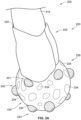
- the tracking element 220 includes an upper portion 222, a lower portion 226, a pattern 230, a first group of visual markers 241, a second group of visual markers 242, and a third group of visual markers 243.
- the upper portion 222 has a generally cylindrical configuration and includes a cavity 224.
- the cavity 224 is sized and shaped to receive the handle 214 of the oral hygiene device 210 therein to removably couple the tracking element 220 to the handle 214 using a press or interference fit.
- the upper portion 222 may, for example, be formed from an elastomeric material in the form of a sleeve and be configured and arranged to receive and conform to the second end of the handle 214. Alternatively, the tracking element 220 can be coupled to the handle 214.
- the tracking element 220 includes a male attachment feature and the second end of the handle 214 can include a cavity that is similar to the cavity 224 and is sized and shaped to receive at least a portion of the male attachment feature therein.
- the tracking element 220 male attachment feature and the cavity of the handle 214 can be coupled using any of the fastening mechanisms described above.
- the tracking element 220 can be removed from the oral hygiene device 210 if the user does not desire to use the tracking element 220 during a given brushing session. Further, the tracking element 220 can be removed from the oral hygiene device 210 and coupled to a second oral hygiene device such as, for example, when the user replaces the oral hygiene device 210 at the end of its useful life or in the event another user desires to use the tracking element 220 on another oral hygiene device. Alternatively, the tracking element 220 and the handle 214 can be unitary and/or monolithic.
- the lower portion 226 of the tracking element 220 can have a generally spherical configuration, although other sizes and shapes are possible.
- each of the plurality of indicators 234 have an amorphous shape that is generally circular-like or oval-like.
- the shape of the plurality of indicators 234 shown in FIG. 2A-2C is preferable because this shape minimizes blur associated with movement of the oral hygiene device 210 and the tracking element 220 when capturing an image of the same.
- one or more of the indicators of the plurality of indicators 234 can have a generally triangular shape, a generally rectangular shape, a polygonal shape, or any combination thereof. While each of the plurality of indicators 234 is shown as having the same shape and size, each of the plurality of indicators 234 can have a different size or substantially the same size (e.g., diameter).
- Each of the plurality of indicators 234 have a first color and the background 232 has a second color that is different than the first color.
- the background 232 is an orange color and each of the plurality of indicators 234 are a black color.
- the background 232 can be a black color and each of the plurality of indicators 234 can be a generally orange color, although other colors for the background 232 and the plurality of indicators 234 are possible (e.g., red, green, blue, yellow, orange, purple, etc.).
- a high contrast between the color of the background 232 and each of the plurality of indicators 234 is preferable so as to clearly define each of the plurality of indicators 234.
- the plurality of indicators 234 defining the pattern 230 on the tracking element 220 can have between about ten indicators and about one hundred indicators, between about twenty indicators and about sixty indicators, between about thirty-five and about forty-five indicators, or any suitable number of indicators.
- the plurality of indicators 234 and the background 232 of the pattern 230 can be formed using a variety of mechanisms.
- at least some of the plurality of indicators 234 and/or the background 232 of the pattern 230 can be printed or embossed on the outer surface of the tracking element 220.
- at least some of the plurality of indicators 234 and/or the background 232 can be integral with the lower portion 226.
- the first group of visual markers 241, the second group of visual markers 242, and the third group of visual markers 243 are coupled to the outer surface of the lower portion 226 and protrude therefrom.
- each visual marker in the groups of visual markers 241, 242, 243 has a generally ovoid, dome-like or semi-spherical shape.
- the first, second, and third groups of visual markers 241, 242, 243 can be coupled to the outer surface of the lower portion 226 using an adhesive connection, for example, or more generally any other suitable mechanism.
- each of the visual markers can be unitary and/or monolithic with the lower portion 226 of the tracking element 220.
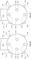
- the first group of visual markers 241 includes a first visual marker 241a, a second visual marker 241b, a third visual marker 241c, and a fourth visual marker 241d.
- the handle 214 has a front surface 214a and a rear surface 214b.
- the cleaning elements (e.g., bristles) on the head extend from the front surface 214a of the handle 214.
- FIG. 2B is a front view of the oral hygiene device 210 (i.e., includes the front surface 214a)
- FIG. 2C is a rear view the oral hygiene device 210 (i.e., includes the rear surface 214b).
- the first group of visual markers 241 extends along a first circumferential length of the lower portion 226 that is proximate to the upper portion 222 and the handle 214. As shown, each of the visual markers in the first group of visual markers 241 are evenly spaced from one another along the first circumferential length.
- the second group of visual markers 242 includes a first visual marker 242a, a second visual marker 242b, a third visual marker 242c, and a fourth visual marker 242d.
- the second group of visual markers 242 extends along a second circumferential length of the lower portion 226 that is spaced from the first circumferential length. As shown, each of the visual markers in the second group of visual markers 242 are evenly spaced from one another along the first circumferential length, but offset circumferentially from the visual markers in the first group of visual markers 241.
- the first visual marker 242a is positioned between the first visual marker 241a and the second visual marker 241b of the first group of visual markers 241 ( FIG.
- the second visual marker 242b is positioned between the second visual marker 241b and the third visual marker 241c of the first group of visual markers 241 ( FIG. 2B )
- the third visual marker 242c is positioned between the third visual marker 241c and the fourth visual marker 241d of the first group of visual markers 241 ( FIG. 2C )
- the fourth visual marker 242d is positioned between the fourth visual marker 241d and the first visual marker 241a of the first group of visual markers 241 (FIG. 2D).
- the third group of visual markers 243 includes a first visual marker 243a, a second visual marker 243b, a third visual marker 243c, and a fourth visual marker 243d.
- the third group of visual markers 243 extends along a third circumferential length of the lower portion 226 that is spaced from the second circumferential length and distal to the upper portion 222 and the handle 214.
- the first circumferential length, the second circumferential length, and the third circumferential length are evenly spaced from one another such that the first group of visual markers 241, the second group of visual markers 242, and the third group of visual markers 243 are evenly spaced from one another.
- the third group of visual markers 243 includes a first visual marker 243a, a second visual marker 243b, a third visual marker 243c, and a fourth visual marker 243d.
- the first visual marker 243a is aligned with the first visual marker 241a of the first group of visual markers 241 such that the first visual marker 243a is positioned between the fourth visual marker 242d and the first visual marker 242a of the second group of visual markers 242.
- the second visual marker 243b is aligned with the second visual marker 241b of the first group of visual markers 241 such that the second visual marker 243b is positioned between the first visual marker 242a and the second visual marker 242b of the second group of visual markers 242.
- the third visual marker 243c is aligned with the third visual marker 241c of the first group of visual markers 241 such that the third visual marker 243c is positioned between the second visual marker 242b and the third visual marker 242c of the second group of visual markers 242.
- the fourth visual marker 243d is aligned with the fourth visual marker 241d of the first group of visual markers 241 such that the fourth visual marker 243d is positioned between the third visual marker 242c and the fourth visual marker 242d of the second group of visual markers 242.
- Each of the visual markers within the first group of visual markers 241, the second group of visual markers 242, and the third group of visual markers 243 has a distinctive color.
- the first visual marker 241a has a first color
- the second visual marker 241b has a second color
- the third visual marker 241c has a third color
- the fourth visual marker 241d has a fourth color.
- the first color, the second color, the third color, and the fourth color are all different from one another.
- the first color, second color, third color, and fourth color are separate and distinct colors that are spaced out along the color spectrum.
- each color can be spaced from the other colors by between about a 150 nm wavelength to a 15 nm wavelength in the color spectrum, about a 100 nm wavelength in the color spectrum to about a 25 nm wavelength in the color spectrum, or about a 75 nm wavelength in the color spectrum to about a 50 nm wavelength in the color spectrum, or the like.
- the first color, second color, third color, and fourth color can be a blue color, a green color, a purple color, a yellow color, a red color, or an orange color, which are spread out substantially equally along the color spectrum.
- the first visual marker 241a is a purple color
- the second visual marker 241b is a blue color
- the third visual marker 241c is a yellow color
- the fourth visual marker 241d is a green color.
- the first visual marker 242a is a yellow color
- the second visual marker 242b is a green color
- the third visual marker 241c is a blue color
- the fourth visual marker 241d is a purple color.
- the first visual marker 243a is a green color
- the second visual marker 243b is a purple color
- the third visual marker 243c is a blue color
- the fourth visual marker 243d is a yellow color.
- each of the four colors blue, green, purple, and yellow
- the attachment 220 can include any number of groups of visual markers including at least one visual marker.
- the attachment 220 can include a first group of visual markers, a second group of visual markers, a third group of visual markers, and a fourth group of visual markers, with each group containing at least one visual marker.
- the at least one visual marker in each group has a different color than the visual markers in the other groups.
- the attachment 220 can include any number of visual markers (e.g., four visual markers, six visual markers, ten visual markers, twenty visual markers, fifty visual markers, etc.) having four or more different colors (e.g., four different colors, six different colors, ten different colors, twenty different colors, etc.). As will be discussed in more detail herein, having four or more visual markers having different colors is preferable to accurately and efficiently track motion of the tracking element 220.
- first group of visual markers 241, the second group of visual markers 242, and the third group of visual markers 243 are each positioned along a circumferential length of the lower portion 226 and are evenly spaced from one another, the visual markers can be positioned relative to one another in any appropriate arrangement (e.g., randomly) on the outer surface of the lower portion 226.
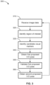
- a method 300 for estimating a pose of the oral hygiene device 210 relative to a location includes, for example, a first step 310, a second step 320, a third step 330, a fourth step 340, a fifth step 350, and a sixth step 360.
- the first step 310 includes receiving image data, from a camera that is the same as or similar to the camera 130 ( FIG. 1 ) described above, that is reproducible as an image of at least a portion of the oral hygiene device 210 and at least a portion of the tracking element 220.
- the image data can be a frame of a video image captured by the camera.
- the camera is positioned relative to the user (e.g., user 101) such that the oral hygiene device 210 and the tracking element 220 are positioned between the camera and the user.
- the captured video or still image includes at least a portion of all three and the background behind the user that is within the field of view of the camera.
- the second step 320 includes analyzing the image data from the first step 310 to identify a region of interest within the image.
- the region of interest is an area of the image received during the first step 310 that includes the tracking element 220.
- the image captured during the first step 310 includes at least a portion of the user and a background behind the user.
- one or more processors that are the same as or similar to the processor 140 ( FIG. 1 ) described above are used to identify the pattern 230 of the tracking element 220 ( FIG. 2A ) using a plurality of filters.
- the plurality of filters includes a movement filter, a color filter, and a shape filter.
- the movement filter detects or identifies movement within the image. Generally, the movement filter detects movement by distinguishing areas of movement in the image compared to stationary areas of the image.
- the movement filter takes advantage of the fact that the pattern 230 is likely to be moving due to corresponding movement of the oral hygiene device 210 and the tracking element 220 to narrow the potential area(s) of the image that could be the region of interest (i.e., contain at least a portion of the pattern 230) by eliminating the stationary background of the image.
- the color filter and the shape filter identify the contrast in color between the background 232 and the plurality of indicators 234 and the shape of each of the plurality of indicators 234. Having detected an area of the image containing the pattern 230, the region of interest is defined as that area and excludes the remainder of the image.
- the image analyzed during the second step 320 is preferably a low resolution image.
- the region of interest can then be upscaled to a higher resolution image for the remainder of the steps of the method 300.
- the pattern 230 of the tracking element 220 can be filtered or detected to identify the region of interest using a machine learning algorithm or an artificial intelligence algorithm.
- Machine learning algorithms may take a variety of forms.
- the method 300 can utilize more basic machine learning tools such as a decision tree ("DT") or an artificial neural network (“ANN").
- DT programs are generally used because of their simplicity and ease of understanding. DT are classification graphs that match input data to questions asked at each consecutive step in a decision tree. The DT program moves down the "branches" of the tree based on the answers to the questions. For example, a first branch may ask if a portion of the image is moving. If yes, a second branch may ask whether the portion of the image includes the pattern 230.
- deep learning algorithms or other more sophisticated machine learning algorithms can be used, such as, for example, a convolutional neural network.
- Machine learning algorithms require training data to identify the features of interest that they are designed to detect. For instance, various methods may be utilized to form the machine learning models including applying randomly assigned initial weights for the network and applying gradient descent using back propagation for deep learning algorithms. In other examples, a neural network with one or two hidden layers can be used without training using this technique. In some examples, the machine learning algorithms will be trained using labeled data, or data that represents certain features, specific actions, or characteristics, including a particular color or a particular shape.
- the third step 330 includes identifying candidate visual markers in the region of interest identified during the second step 320.
- candidate visual markers are sub-regions of the region of interest that could be an actual visual marker (e.g., one of the visual markers of the groups of visual markers 241, 242, or 243 in FIGS. 2A-2C ) on the tracking element 220.
- the region of interest is segmented in a plurality of sub-regions using a color segmentation algorithm. Each sub-region is defined by a plurality of pixels of the region of interest that have a common color.
- the color segmenting algorithm assumes that objects are colored distinctively and seeks to identify gross color differences between adjacent pixels in an image.
- the color segmenting algorithm uses the L*a*b color space, which defines colors in terms of luminosity ("L"), where the color falls along the red-green axis ("*a"), and where the color falls along the blue-yellow axis ("*b").
- L luminosity
- *a red-green axis
- *b blue-yellow axis
- the region of interest identified in the second step 320 is converted from a RGB color space to the L*a*b color space to perform the color segmenting algorithm.
- the color segmenting algorithm separates adjacent pixels having distinctive colors from one another to form a plurality of sub-regions. The average color in the L*a*b color space of each of the plurality of sub-regions is then calculated.
- the color of the visual markers in the first group 241, the second group 242, and the third group 243 preferably is one of blue, green, purple, yellow color, red, or orange.
- a sub-region of the region of interest having a blue, green, purple, or yellow color could be a candidate visual marker.
- the region of interest is limited to an area encompassing the tracking element 220, the region of interest may still include a portion of the user or the background behind the user, which can create false positive for a candidate visual marker.
- the user may be wearing clothing which has one or more of the same or similar colors as the visual markers.
- the third step 330 also includes a shape filter and a size filter.
- the visual markers of the first group of visual markers 241, the second group of visual markers 242, and the third group of visual markers 243 have a generally dome-like or hemispheric shape. When viewed in a two-dimensional image such as the region of interest, these visual markers have a generally circular shape.
- the shape filter and the size filter are used to detect the generally circular shape of the visual markers within the region of interest. These filters aid in discriminating between a visual marker and, for example, the clothing of the user.
- the fourth step 340 includes obtaining a first proposed three-dimensional pose of the oral hygiene device 210.
- the first proposed three-dimensional pose includes the position and orientation (rotation and translation) of the oral hygiene device 210 relative to the camera.
- the fourth step 340 will not initialize until at least four candidate visual markers are identified during the third step 330. If less than four candidate visual markers are identified during the third step 330, the method 300 is repeated until at least four candidate visual markers are identified.
- the fourth step 340 includes a first sub-step 342, a second sub-step 348, a third sub-step 348, and a fourth sub-step 348.
- the first sub-step 342 includes grouping the candidate visual markers identified during the third step 330 ( FIG. 3 ) into discrete sets of candidate visual markers.
- each of the discrete sets of candidate visual markers includes four candidate visual markers.
- the second sub-step 348 includes grouping model markers from a three-dimensional model of the oral hygiene device 210 and the tracking element 220 into discrete steps.
- the three-dimensional model is stored in a memory device that is the same as or similar to the memory device 150 described above ( FIG. 1 ).
- the three-dimensional model is a representation of the actual oral hygiene device 210 and the tracking element 220.
- the three-dimensional model includes representations of the first group of visual markers 241, the second group of visual markers 242, and the third group of visual markers 243.
- the number of model markers in each of the discrete sets of model markers is equal to the number of candidate visual markers in the first discrete set of candidate visual markers grouped together during the first step 342 (e.g., four candidate visual markers and four model markers).
- the third sub-step 348 includes selecting a first discrete set of candidate visual markers and a first discrete set of model markers.
- the first discrete set of candidate visual markers includes four visual markers and the first discrete set of model markers includes four model markers.
- the fourth sub-step 348 includes inputting the first discrete set of candidate visual markers and the first discrete set of model markers selected during the third sub-step 348 into a perspective-three-point (“P3P") algorithm.
- P3P perspective-three-point
- the P3P algorithm is based on the law of cosines and is used to estimate an object pose (a rotation and translation) relative to the camera placement.
- the P3P algorithm compares two-dimensional points taken from an image with three-dimensional points taken from a three-dimensional model.
- four two-dimensional points defined in an image coordinate system and four three-dimensional points defined in a three-dimensional model coordinate system are provided.
- Three sets of points, each set including a two-dimensional point and a three-dimensional point, are used to solve the P3P equation system and determine up to four possible sets of distances between the two-dimensional points and the optical center of the camera. These four sets of distances are converted into four pose configurations.
- the fourth set of 2D/3D points is then used to select the best or most correct pose configuration against the four proposals.
- the first proposed three-dimensional pose includes a rotational and a translational position of the oral hygiene device 210 that permits the position of the oral hygiene device 210 relative to the camera to be determined.
- the fourth step 340 will not initialize until four candidate visual markers are identified during the third step 330. This is because solving the P3P algorithm requires four candidate visual markers and four model markers. If less than four candidate visual markers are identified in the third step 330, the P3P algorithm equation system generally cannot be solved without more data.
- the fifth step 350 ( FIG. 3 ) includes validating the first proposed three-dimensional pose of the oral hygiene device 210 determined during the fourth step 340. It is possible that the first discrete set of candidate visual markers and the first discrete set of model markers selected in sub-step 348 yield a proposed three-dimensional pose that is incorrect (e.g., a pose that is not physically possible). Thus, the fifth step 350 is generally used to validate or reject the proposed three-dimensional pose obtained during the fourth step 340.
- the fifth step 350 includes a first sub-step 352, a second sub-step 354, a third sub-step 356, and a fourth sub-step 358.
- the first sub-step 352 includes predicting the positions of the candidate visual markers within the region of interest. Based on the first proposed three-dimensional pose calculated during the fourth step 340, and the known positions of visual markers from the three-dimensional model of the oral hygiene device 210 and the tracking element 220, the position of the visual markers within the region of interest can be predicted. In other words, the predicted positions indicate where candidate visual markers should be located in the region of interest if the first proposed three-dimensional pose is correct, and where candidate visual markers should not be located.
- the oral hygiene device 210 may be predicted that six visual markers will be visible in the region of interest if the oral hygiene device 210 has the same pose as the first proposed three-dimensional pose.
- the position of these six visual markers relative to one another in the region of interest is determined from the three-dimensional model of the oral hygiene device.
- the second sub-step 354 includes comparing the candidate visual markers identified in the region of interest with the predicted positions of the visual markers. More specifically, the number and position of the candidate visual markers is compared to the predicted number and predicted position of the visual markers (first sub-step 354 of the fifth step 350). If it is determined that the positions of a predetermined number of the candidate visual markers correspond to the predicted positions, the first proposed three-dimensional pose is validated (sub-step 356). If less than the predetermined number of candidate markers correspond to the predicted positions, the first proposed three-dimensional pose is rejected (sub-step 358).
- the first sub-step 352 predicts that six candidate visual markers will be visible in the region of interest, and predicts the position of each of these six candidate visual markers relative to one another.
- the third step 330 identified ten candidate visual markers within the region of interest. If, for example, a candidate visual marker corresponds to five of the six predicted visual markers, the first proposed three-dimensional pose is validated (sub-step 356) and the fifth step 350 is completed. The other four candidate visual markers are simply considered to be noise or inaccurate. Alternatively, if there are thirty candidate visual markers identified during the third step 330, and for example, twenty-five of the thirty do not correspond to a predicted position, the proposed three-dimensional pose may be rejected.
- the predetermined number of correspondences required to validate a proposed three-dimensional pose can be expressed as a percentage, and can be at least about 50% of the predicted positions of the visual markers correspond to positions of candidate visual markers, at least about 60% of the predicted positions of the visual markers correspond to positions of candidate visual markers, at least about 70% of the predicted positions of the visual markers correspond to position of candidate visual markers, at least about 80% of the predicted positions of the visual markers correspond to positions of candidate visual markers, at least about 90% of the predicted positions of the visual markers correspond to positions of candidate visual markers, or 100% of the predicted positions of the visual markers correspond to positions of candidate visual markers).
- the predetermined number is a statistically significant number such that it can be determined that the first proposed three-dimensional pose is correct with a suitable statistical certainty (e.g., 95% statistical certainty, 85% statistical certainty, 75% statistical certainty, etc.).
- the second sub-step 348 ( FIG. 4 ) of the fourth step 340 is repeated.
- a second discrete set of candidate visual markers and a second discrete set of model markers are selected.
- At least one of the second discrete set of candidate visual markers and the second discrete set of models markers includes a set of candidate visual markers or model markers that is different from the first discrete set of candidate visual markers and/or the second discrete set of model markers.
- These sets are then inputted into the P3P algorithm in sub-step 348 to obtain a second proposed three-dimensional pose of the oral hygiene device 210.
- the second proposed three-dimensional pose is then validated or rejected during the fifth step 350.
- Steps 348 through 354 are repeated until a proposed three-dimensional pose is validated (sub-step 356).
- each of the first group of visual markers 241, the second group of visual markers 242, and the third group of visual markers 243 includes four visual markers, and each of the four visual markers in each group has a different color.
- the grouping of candidate visual markers and model markers can then be further conditioned such that each group not only is limited to four visual markers, but each visual marker in the group of four has a different color.
- the number of possible combinations that may need to be inputted into the P3P algorithm (sub-step 348) before validating a proposed three-dimensional pose (sub-step 356) is reduced from, for example, the hundreds of thousands to several hundred. This reduces the processing/computational requirements such that the method can be implemented on, for example, a smartphone with limited processing power.
- the sixth step 360 includes obtaining a second proposed three-dimensional pose of the oral hygiene device 210 based on the validated first proposed three-dimensional pose of the oral hygiene device 210.
- the second proposed three-dimensional pose of the oral hygiene device 210 is calculated in a similar manner as the first proposed three-dimensional pose during the fifth step 350.
- the positions of each of the visual markers in the region of interest are predicted.
- the sixth step 360 selects only the candidate visual markers ("correct candidate visual markers") that correspond to predicted visual markers, ignoring candidate visual markers that are incorrect based on the predicted positions. These correct candidate visual markers are then compared to model markers from the three-dimensional model of the oral hygiene device 210 using an iterative pose estimation algorithm and linear regressions to obtain a second proposed three-dimensional pose of the oral hygiene device 210.
- the second proposed three-dimensional pose of the oral hygiene device 210 is generally more accurate than the first proposed three dimensional pose (fourth step 340), but requires more processing/computation time to determine.
- the method 300 can be repeated one or more times.
- the first step 310 is repeated and includes receiving image data that is reproducible as a second image of at least a portion of the oral hygiene device 210 and the tracking element 220.
- the second image can be a second frame of a video image that is taken subsequent to the image used during the initial iteration of the method 300.
- the second step 320 is then repeated to identify a second region of interest in the second image received during the first step 310.
- detection of the pattern 230 of the tracking element 220 to identify the region of interest is bypassed.
- the second region of interest is selected using the second three-dimensional pose estimation (sixth step 360), and the second region of interest is defined an area of the second image in which at least a portion of the tracking element 220 is positioned. Because the second step 320 in the second iteration of the method 300 does not require detection of the pattern 230 using a plurality of filters, the required processing/computation time to complete the second step 320 is reduced.
- the third step 330 is then repeated to identify all of the candidate visual markers in the second region of interest using the color segmenting algorithm described above.
- the oral hygiene device 210 will be used in a bathroom that may have bright or intense lighting, which can be further amplified by reflections in a bathroom mirror. Further, movement of the oral hygiene device 210 may cause the lighting conditions in the region of interest to change based on position of the oral hygiene device relative to a light source (e.g., the user may cast a shadow on a portion of the oral hygiene device 210 in a particular pose). The lighting conditions and/or movement of the oral hygiene device 210 may affect the amount of light reflecting off of the visual markers of the tracking element 220.
- the threshold for distinguishing colors in the color segmenting algorithm can be adjusted based on the three-dimensional pose estimation obtained in the sixth step 360 of the first iteration of the method 300. This threshold is then updated each time the third step 330 is completed as the method 300 is repeated.
- the fourth step 340, the fifth step 350, and the sixth step 360 are then repeated in the same or similar manner as described above to obtain another second three-dimensional pose estimation of the oral hygiene device 210.
- Steps 310 through 360 can then be repeated a plurality of times (e.g., ten times, fifty times, one hundred times, one thousand times, etc.) after the second iteration described above description to track motion of the oral hygiene device 210.
- the sixth step 360 will output a series of estimated three-dimensional poses of the oral hygiene device 210 as the method 300 is repeated, which can be then used to track the movement of the oral hygiene device 210 over time.
- This repeating of the method 300 can be used to track the motion of the oral hygiene device 210 during, for example, a brushing session in which a user is brushing their teeth.
- Data relevant to the quality of brushing by a user or the overall dental health of the user's teeth can be collected and analyzed based on the motion data. For example, a brush stroke type (e.g., a side-to-side stroke, an angular stroke, or a circular stroke) can be determined.
- the system 100 can also be utilized to determine the position and orientation of a face of a user. For example, using the camera 104, the system 100 receives an image of at least a portion of the face of the user. Using the processor 140 and the memory 150 and a facial recognition algorithm, the position and orientation of the face can be determined. For example, the system 100 may determine the position of the user's eyes, mouth, or nose (or any combination thereof) using, for example, a plurality of filters, machine-learning algorithms, or the like. In one example, the position of the user's mouth can be estimated based on the position of the user's eyes and a distance between the eyes and mouth of the user.
- the position of the oral hygiene device 210 can be determined not only with respect to the camera, but to the mouth of the user. Thus, the position of the oral hygiene device relative to the teeth of the user and thus determine and whether a user has a brushed a certain section of teeth can be determined.
- the method 300 further includes an initial calibration step to determine the rotational position of the tracking element 220 relative to the oral hygiene device 210.
- the calibration step can initially determine the rotational position of the tracking element 220 on the oral hygiene device 210 and communicate that position to adjust the three-dimensional model so that the rotational position of the tracking element 220 in the three-dimensional model corresponds with the rotational position on the actual oral hygiene device 210.
- the method 300 is agnostic to how the tracking element 220 is coupled to the handle 214 of the oral hygiene device 210.
- the tracking element 220 can be used to track motion of the oral hygiene device 210 using the method 300 (or other similar methods) without requiring any electronics or sensors (e.g., an accelerometer) in the tracking element 220.
- the tracking element 220 can include such sensors in some implementations to aid in tracking motion of the oral hygiene device 210, such sensors may, for example, increase the cost of the tracking element 220, require the tracking element 220 to be charged periodically prior to use, or increase the weight of the tracking element 220 and thus interfere with a user's (e.g., a child's) brushing given the added weight at the end of the oral hygiene device 210.
- the system 100 and method 300 can be used to track the motion of any other object coupled to the tracking element 220.
- a tracking element that is the same as or similar to the tracking element 220 can be coupled to an end of an object with a similar shape as the oral hygiene device 210, such as, for example, a baseball bat, a hockey stick, a golf club, or the like.
- a tracking element that is similar to the tracking element 220 can more generally be attached to an object with any other shape to track the motion of the object.
Landscapes
- Health & Medical Sciences (AREA)
- Engineering & Computer Science (AREA)
- Life Sciences & Earth Sciences (AREA)
- Physics & Mathematics (AREA)
- Computer Vision & Pattern Recognition (AREA)
- General Health & Medical Sciences (AREA)
- Dentistry (AREA)
- Public Health (AREA)
- Veterinary Medicine (AREA)
- Animal Behavior & Ethology (AREA)
- General Physics & Mathematics (AREA)
- Theoretical Computer Science (AREA)
- Multimedia (AREA)
- Biophysics (AREA)
- Pathology (AREA)
- Molecular Biology (AREA)
- Medical Informatics (AREA)
- Heart & Thoracic Surgery (AREA)
- Biomedical Technology (AREA)
- Oral & Maxillofacial Surgery (AREA)
- Surgery (AREA)
- Physiology (AREA)
- Epidemiology (AREA)
- Human Computer Interaction (AREA)
- Nuclear Medicine, Radiotherapy & Molecular Imaging (AREA)
- Radiology & Medical Imaging (AREA)
- Dental Tools And Instruments Or Auxiliary Dental Instruments (AREA)
- Length Measuring Devices By Optical Means (AREA)
- Image Processing (AREA)
- Image Analysis (AREA)
Claims (15)
- Procédé d'estimation d'une pose d'un dispositif d'hygiène buccale (110 ; 210) par rapport à un emplacement, le dispositif d'hygiène buccale (110 ; 210) comprenant un motif (122, 230) et une pluralité de groupes de marqueurs visuels (124, 241 à 243), le procédé comprenant :a) la réception de données d'image reproductibles sous la forme d'une image d'au moins une partie du dispositif d'hygiène buccale (110 ; 210) ;b) l'analyse, à l'aide d'un ou plusieurs processeurs (140), des données d'image pour identifier une région d'intérêt dans l'image, la région d'intérêt incluant au moins une partie du motif (122, 230) à l'intérieur ;c) en réponse à l'identification de la région d'intérêt, la segmentation, à l'aide d'au moins l'un desdits un ou plusieurs processeurs (140), de la région d'intérêt en une pluralité de sous-régions, chacune de la pluralité de sous-régions étant définie par une pluralité de pixels ayant une couleur commune ;d) l'identification, à l'aide d'au moins l'un desdits un ou plusieurs processeurs (140), de tous les marqueurs visuels candidats parmi la pluralité de groupes de marqueurs visuels (124, 241 à 243) dans la région d'intérêt, les marqueurs visuels candidats correspondant aux sous-régions de la région d'intérêt ;e) la création d'une pluralité d'ensembles distincts de marqueurs visuels candidats ;f) la sélection d'un premier ensemble parmi la pluralité d'ensembles distincts des marqueurs visuels candidats ;g) la sélection d'un premier ensemble parmi une pluralité d'ensembles distincts de marqueurs modèles associés à un modèle tridimensionnel du dispositif d'hygiène buccale (110, 210) ;h) l'évaluation de l'ensemble sélectionné de marqueurs visuels candidats et l'ensemble sélectionné de marqueurs modèles à l'aide d'un algorithme de perspective à trois points pour obtenir une pose tridimensionnelle proposée du dispositif d'hygiène buccale (110, 210) ;i) sur la base de la pose tridimensionnelle proposée du dispositif d'hygiène buccale (110, 210), la prédiction d'une position dans la région d'intérêt pour un nombre prédéterminé de marqueurs visuels candidats ;j) la comparaison des positions prédites pour le nombre prédéterminé de marqueurs visuels candidats avec les positions réelles de tous les marqueurs visuels candidats dans la région d'intérêt ;k) en réponse à une détermination selon laquelle au moins une partie substantielle des positions prédites correspondent aux positions réelles, la validation de la pose tridimensionnelle proposée ; etl) en réponse à une détermination selon laquelle moins d'une partie substantielle des positions prédites correspondent aux positions réelles, la répétition des étapes f) à k).
- Procédé selon la revendication 1, comprenant en outre, en réponse à la validation de la pose tridimensionnelle proposée, la comparaison de tous les marqueurs visuels candidats et de tous les marqueurs modèles à l'aide d'un algorithme pour obtenir une seconde pose tridimensionnelle proposée du dispositif d'hygiène buccale (110, 210).
- Procédé selon la revendication 1, dans lequel l'analyse des premières données d'image comprend l'utilisation d'un ou plusieurs filtres, lesdits un ou plusieurs filtres comprenant un filtre de mouvement, un filtre de couleur, un filtre de forme ou toute combinaison de ceux-ci.
- Procédé selon la revendication 1, dans lequel l'identification de tous les marqueurs visuels candidats est basée sur une forme et une couleur de chacune de la pluralité de sous-régions.
- Procédé selon la revendication 1, dans lequel chacun de la pluralité d'ensembles distincts des marqueurs visuels candidats comprend au moins quatre marqueurs visuels candidats et chacun de la pluralité d'ensembles distincts des marqueurs modèles comprend au moins quatre marqueurs modèles.
- Procédé selon la revendication 1, comprenant en outre :la réception d'un deuxième ensemble de données d'image reproductibles sous la forme d'une seconde image d'au moins une partie du dispositif d'hygiène buccale (110, 210) ;l'identification d'une seconde région d'intérêt dans la seconde image sur la base de la pose tridimensionnelle validée du dispositif d'hygiène buccale (110, 210).
- Procédé selon la revendication 6, comprenant en outre :
l'ajustement, sur la base de la pose tridimensionnelle validée du dispositif d'hygiène buccale (110, 210), d'un seuil pour segmenter la seconde région d'intérêt afin d'aider à identifier les pixels ayant des couleurs différentes dans la seconde région d'intérêt. - Système de suivi de mouvement (100) comprenant :un dispositif d'hygiène buccale (110, 210) comprenant une tête (112) et une poignée (114, 214) ;un élément de suivi (120, 220) couplé au dispositif d'hygiène buccale (110, 210) comprenant un motif (122, 230) et une pluralité de groupes de marqueurs visuels (124, 241 à 243) ;une caméra (130) ;un ou plusieurs processeurs (140) ; etun dispositif de mémoire (150) stockant des instructions qui, lorsqu'elles sont exécutées par au moins l'un desdits un ou plusieurs processeurs (140), amènent le système de suivi de mouvement (100) à :capturer, à l'aide de la caméra (130), une image d'au moins une partie du dispositif d'hygiène buccale (110, 210) ;analyser, à l'aide d'au moins l'un desdits un ou plusieurs processeurs (140), l'image pour identifier une région d'intérêt au sein de l'image, la région d'intérêt incluant au moins une partie du motif (122, 230) de l'élément de suivi (120, 220) à l'intérieur ;identifier, à l'aide d'au moins l'un desdits un ou plusieurs processeurs (140), tous les marqueurs visuels candidats parmi la pluralité de groupes de marqueurs visuels (124, 241 à 243) dans la région d'intérêt,dans lequel les marqueurs visuels candidats correspondent aux sous-régions de la région d'intérêt ;créer une pluralité d'ensembles distincts des marqueurs visuels candidats ;sélectionner un premier ensemble parmi la pluralité d'ensembles distincts de marqueurs visuels candidats ;sélectionner un premier ensemble parmi une pluralité d'ensembles distincts de marqueurs modèles associés à un modèle tridimensionnel du dispositif d'hygiène buccale (110, 210) stocké dans le dispositif de mémoire (150) ;évaluer l'ensemble sélectionné de marqueurs visuels candidats et l'ensemble sélectionné de marqueurs modèles à l'aide d'un algorithme de perspective à trois points pour obtenir une pose tridimensionnelle proposée du dispositif d'hygiène buccale (110, 210) ;sur la base de la pose tridimensionnelle proposée du dispositif d'hygiène buccale (110, 210), prédire une position dans la région d'intérêt pour un nombre prédéterminé de marqueurs visuels candidats ;comparer les positions prédites pour le nombre prédéterminé de marqueurs visuels candidats avec les positions réelles de tous les marqueurs visuels candidats dans la région d'intérêt ; eten réponse à une détermination selon laquelle au moins une partie substantielle des positions prédites correspondent aux positions réelles, valider la pose tridimensionnelle proposée.
- Système selon la revendication 8, dans lequel l'élément de suivi (110, 220) comprend une cavité (224) pour y recevoir une partie de la poignée (114, 214) du dispositif d'hygiène buccale (110, 220).
- Système selon la revendication 8, dans lequel le motif (230) de l'élément de suivi (220) affleure une surface extérieure de l'élément de suivi (220) et la pluralité de groupes de marqueurs visuels (241 à 243) dépassent de la surface extérieure de l'élément de suivi (220).
- Système selon la revendication 10, dans lequel les marqueurs visuels de chacun de la pluralité de groupes de marqueurs visuels (241 à 243) ont une forme généralement semi-sphérique.
- Système selon la revendication 8, dans lequel le motif (230) de l'élément de suivi (220) comprend un fond (232) ayant une première couleur et une pluralité d'indicateurs (234) superposés sur le fond (232), la pluralité d'indicateurs (234) ayant une deuxième couleur qui est différente de la première couleur.
- Système selon la revendication 8, dans lequel un premier groupe (241; 242; 243) de la pluralité de groupes de marqueurs visuels (241 à 243) comprend un premier marqueur visuel (241a; 242a; 243a) ayant une première couleur, un deuxième marqueur visuel (241b; 242b; 243b) ayant une deuxième couleur, un troisième marqueur visuel (241c; 242c; 243c) ayant une troisième couleur, et un quatrième marqueur visuel (241d; 242d; 243d) ayant une quatrième couleur.
- Système selon la revendication 8, dans lequel un premier groupe de la pluralité de groupes de marqueurs visuels (241 à 243) comprend un premier marqueur visuel ayant une première couleur, un deuxième marqueur visuel ayant la première couleur, un troisième marqueur visuel ayant la première couleur, et un quatrième marqueur visuel ayant la première couleur.
- Système selon la revendication 8, comprenant en outre un dispositif mobile comprenant un boîtier, dans lequel la caméra (130), lesdits un ou plusieurs processeurs (140), le dispositif de mémoire (150), ou toute combinaison de ceux-ci, sont au moins partiellement disposés à l'intérieur du boîtier du dispositif mobile.
Priority Applications (1)
| Application Number | Priority Date | Filing Date | Title |
|---|---|---|---|
| EP24187018.7A EP4418210A1 (fr) | 2017-12-28 | 2018-12-14 | Systeme und verfahren zur bestimmung der dreidimensionale ausrichtung eines mundhygienegerätes mit hilfe sichtbarer markierungen |
Applications Claiming Priority (2)
| Application Number | Priority Date | Filing Date | Title |
|---|---|---|---|
| US201762611112P | 2017-12-28 | 2017-12-28 | |
| PCT/US2018/065607 WO2019133287A1 (fr) | 2017-12-28 | 2018-12-14 | Systèmes et procédés d'estimation d'une pose tridimensionnelle d'un dispositif d'hygiène buccale présentant des repères visuels |
Related Child Applications (2)
| Application Number | Title | Priority Date | Filing Date |
|---|---|---|---|
| EP24187018.7A Division-Into EP4418210A1 (fr) | 2017-12-28 | 2018-12-14 | Systeme und verfahren zur bestimmung der dreidimensionale ausrichtung eines mundhygienegerätes mit hilfe sichtbarer markierungen |
| EP24187018.7A Division EP4418210A1 (fr) | 2017-12-28 | 2018-12-14 | Systeme und verfahren zur bestimmung der dreidimensionale ausrichtung eines mundhygienegerätes mit hilfe sichtbarer markierungen |
Publications (2)
| Publication Number | Publication Date |
|---|---|
| EP3672448A1 EP3672448A1 (fr) | 2020-07-01 |
| EP3672448B1 true EP3672448B1 (fr) | 2024-09-18 |
Family
ID=65003516
Family Applications (2)
| Application Number | Title | Priority Date | Filing Date |
|---|---|---|---|
| EP18830615.3A Active EP3672448B1 (fr) | 2017-12-28 | 2018-12-14 | Systemes et procedes d'estimation de la pose tridimensionnelle d'un dispositif d'hygiene bucco-dentaire a marqueurs visuels |
| EP24187018.7A Pending EP4418210A1 (fr) | 2017-12-28 | 2018-12-14 | Systeme und verfahren zur bestimmung der dreidimensionale ausrichtung eines mundhygienegerätes mit hilfe sichtbarer markierungen |
Family Applications After (1)
| Application Number | Title | Priority Date | Filing Date |
|---|---|---|---|
| EP24187018.7A Pending EP4418210A1 (fr) | 2017-12-28 | 2018-12-14 | Systeme und verfahren zur bestimmung der dreidimensionale ausrichtung eines mundhygienegerätes mit hilfe sichtbarer markierungen |
Country Status (9)
| Country | Link |
|---|---|
| US (3) | US10799155B2 (fr) |
| EP (2) | EP3672448B1 (fr) |
| CN (1) | CN111491537B (fr) |
| AU (3) | AU2018393954B2 (fr) |
| BR (1) | BR112020012480B1 (fr) |
| CA (1) | CA3085135A1 (fr) |
| MX (2) | MX2020006659A (fr) |
| RU (1) | RU2754316C1 (fr) |
| WO (1) | WO2019133287A1 (fr) |
Families Citing this family (9)
| Publication number | Priority date | Publication date | Assignee | Title |
|---|---|---|---|---|
| US10962780B2 (en) * | 2015-10-26 | 2021-03-30 | Microsoft Technology Licensing, Llc | Remote rendering for virtual images |
| USD855330S1 (en) * | 2017-12-28 | 2019-08-06 | Colgate-Palmolive Company | Toothbrush |
| WO2020012476A1 (fr) * | 2018-07-13 | 2020-01-16 | Plaqless Ltd | Appareil de détection de maladies et de risques oraux |
| AU2018435277B2 (en) | 2018-08-03 | 2022-07-14 | Colgate-Palmolive Company | Oral care system including an oral care implement and a tracking attachment, tracking attachment thereof, and method of assembling the same |
| WO2023114034A1 (fr) | 2021-12-13 | 2023-06-22 | Colgate-Palmolive Company | Système de soins buccodentaires comprenant un instrument de soins buccodentaires doté de caractéristiques de suivi du mouvement |
| US12190537B2 (en) * | 2022-04-04 | 2025-01-07 | Microsoft Technology Licensing, Llc | Repairing image depth values for an object with a light absorbing surface |
| CN115607320A (zh) * | 2022-10-25 | 2023-01-17 | 无锡赛锐斯医疗器械有限公司 | 一种口外扫描连接基台位姿测量仪及位姿参数确定方法 |
| TWI856531B (zh) * | 2023-02-24 | 2024-09-21 | 林易岳 | 根據影像評估口腔乾燥或污染的電腦程式及電腦可讀取媒體 |
| CN116993790B (zh) * | 2023-09-27 | 2023-12-08 | 深圳卡尔文科技有限公司 | 一种种植导航配准方法、系统和存储介质 |
Family Cites Families (22)
| Publication number | Priority date | Publication date | Assignee | Title |
|---|---|---|---|---|
| GB0109444D0 (en) * | 2001-04-17 | 2001-06-06 | Unilever Plc | Toothbrush usage monitoring system |
| US20040236628A1 (en) * | 2003-05-21 | 2004-11-25 | James Kemp | Method of marketing or promoting consumer goods |
| US8330823B2 (en) | 2006-11-01 | 2012-12-11 | Sony Corporation | Capturing surface in motion picture |
| GB0622451D0 (en) * | 2006-11-10 | 2006-12-20 | Intelligent Earth Ltd | Object position and orientation detection device |
| US20090215015A1 (en) | 2008-02-21 | 2009-08-27 | Raindrop Network Ltd. | Method and Apparatus for Developing a Proper Tooth Brushing Technique |
| US9586135B1 (en) * | 2008-11-12 | 2017-03-07 | David G. Capper | Video motion capture for wireless gaming |
| US10086262B1 (en) | 2008-11-12 | 2018-10-02 | David G. Capper | Video motion capture for wireless gaming |
| AU2010336464B2 (en) * | 2009-12-23 | 2014-01-16 | Colgate-Palmolive Company | Diagnostic oral device |
| RU2526672C2 (ru) | 2009-12-23 | 2014-08-27 | Колгейт-Палмолив Компани | Устройство для идентификации заболеваний ротовой полости |
| CA2870480A1 (fr) * | 2012-04-13 | 2013-10-17 | Lightcraft Technology Llc | Suivi de precision hybride |
| EP3011505A1 (fr) * | 2013-06-18 | 2016-04-27 | Koninklijke Philips N.V. | Lecteur de dispositif et son moyen de génération d'image |
| EP3065919B1 (fr) * | 2013-11-06 | 2020-01-08 | Koninklijke Philips N.V. | Système et procédé pour traiter la tête d'un usager |
| CN104660646A (zh) * | 2013-11-20 | 2015-05-27 | 江南大学 | 一种基于多加速度传感器和ZigBee网络的牙刷动作采集系统 |
| US9510757B2 (en) * | 2014-05-07 | 2016-12-06 | Align Technology, Inc. | Identification of areas of interest during intraoral scans |
| WO2016020803A1 (fr) * | 2014-08-04 | 2016-02-11 | Sarubbo Davide | Système de vérification d'une procédure d'hygiène buccale correcte |
| EP3313233A1 (fr) * | 2015-06-29 | 2018-05-02 | Koninklijke Philips N.V. | Procédés et systèmes pour l'extraction de caractéristiques de mouvement d'un utilisateur à l'aide d'un capteur à effet hall afin de fournir une rétroaction à l'utilisateur |
| EP3141151B1 (fr) | 2015-09-08 | 2023-10-18 | Braun GmbH | Détermination d'une partie de corps en cours de traitement d'un utilisateur |
| CN109152471A (zh) * | 2016-03-14 | 2019-01-04 | 科里布里公司 | 具有视觉识别功能以用于监测依从性的口腔卫生系统 |
| US10357342B2 (en) * | 2016-09-21 | 2019-07-23 | uLab Systems, Inc. | Digital dental examination and documentation |
| US11213120B2 (en) * | 2016-11-14 | 2022-01-04 | Colgate-Palmolive Company | Oral care system and method |
| CN107028672A (zh) * | 2017-05-23 | 2017-08-11 | 乔元秀 | 高精度定位识别方法 |
| US11297933B2 (en) * | 2018-08-03 | 2022-04-12 | Colgate-Palmolive Company | Powered oral care implement including a tracking module and tracking module thereof |
-
2018
- 2018-12-14 EP EP18830615.3A patent/EP3672448B1/fr active Active
- 2018-12-14 EP EP24187018.7A patent/EP4418210A1/fr active Pending
- 2018-12-14 US US16/220,117 patent/US10799155B2/en active Active
- 2018-12-14 CA CA3085135A patent/CA3085135A1/fr active Pending
- 2018-12-14 RU RU2020124894A patent/RU2754316C1/ru active
- 2018-12-14 MX MX2020006659A patent/MX2020006659A/es unknown
- 2018-12-14 BR BR112020012480-0A patent/BR112020012480B1/pt active IP Right Grant
- 2018-12-14 AU AU2018393954A patent/AU2018393954B2/en active Active
- 2018-12-14 CN CN201880081561.5A patent/CN111491537B/zh active Active
- 2018-12-14 WO PCT/US2018/065607 patent/WO2019133287A1/fr not_active Ceased
-
2020
- 2020-07-13 MX MX2024009356A patent/MX2024009356A/es unknown
- 2020-09-04 US US17/012,186 patent/US11006862B2/en active Active
-
2021
- 2021-04-12 US US17/301,675 patent/US11363971B2/en active Active
-
2022
- 2022-01-06 AU AU2022200066A patent/AU2022200066B2/en active Active
-
2023
- 2023-11-13 AU AU2023266234A patent/AU2023266234B2/en active Active
Also Published As
| Publication number | Publication date |
|---|---|
| WO2019133287A1 (fr) | 2019-07-04 |
| BR112020012480A2 (pt) | 2020-11-24 |
| AU2023266234B2 (en) | 2025-05-15 |
| BR112020012480B1 (pt) | 2023-11-21 |
| CA3085135A1 (fr) | 2019-07-04 |
| MX2020006659A (es) | 2020-08-31 |
| CN111491537A (zh) | 2020-08-04 |
| AU2018393954B2 (en) | 2021-10-07 |
| CN111491537B (zh) | 2022-05-13 |
| US20190200902A1 (en) | 2019-07-04 |
| EP3672448A1 (fr) | 2020-07-01 |
| US20210228112A1 (en) | 2021-07-29 |
| AU2018393954A1 (en) | 2020-07-30 |
| AU2022200066B2 (en) | 2023-08-17 |
| US11363971B2 (en) | 2022-06-21 |
| RU2754316C1 (ru) | 2021-09-01 |
| EP4418210A1 (fr) | 2024-08-21 |
| AU2023266234A1 (en) | 2023-12-07 |
| US11006862B2 (en) | 2021-05-18 |
| AU2022200066A1 (en) | 2022-02-03 |
| MX2024009356A (es) | 2024-08-09 |
| US20200397347A1 (en) | 2020-12-24 |
| US10799155B2 (en) | 2020-10-13 |
Similar Documents
| Publication | Publication Date | Title |
|---|---|---|
| EP3672448B1 (fr) | Systemes et procedes d'estimation de la pose tridimensionnelle d'un dispositif d'hygiene bucco-dentaire a marqueurs visuels | |
| US10092220B2 (en) | System and method for motion capture | |
| KR102339915B1 (ko) | 셀피를 촬영하도록 사용자를 안내하기 위한 시스템 및 방법 | |
| US9149179B2 (en) | System and method for identifying eye conditions | |
| CN111279353B (zh) | 用于确定眼睛的姿势的方法和系统 | |
| CN110495962A (zh) | 监测牙刷位置的方法及其牙刷和设备 | |
| Rauschert et al. | A generative model for simultaneous estimation of human body shape and pixel-level segmentation | |
| CN109523551A (zh) | 一种获取机器人行走姿态的方法及系统 | |
| CN114303117B (zh) | 使用离轴相机的眼睛跟踪和注视估计 | |
| US20110222742A1 (en) | Pipeline for generating an intrinsic image | |
| US12327389B2 (en) | Image classification using retinal ganglion cell modelling | |
| Marcon et al. | Smart toothbrushes: inertial measurement sensors fusion with visual tracking | |
| KR20220158155A (ko) | 인공지능 기반의 가상 무게감 인식 시스템 및 그 방법 | |
| Akhavizadegan et al. | Real-time automated contour based motion tracking using a single-camera for upper limb angular motion measurement | |
| CN121214007A (zh) | 基于ai技术的蟹类眼动特征获取与活性评估方法、装置及电子设备 | |
| Barca et al. | Noise filtering of new motion capture markers using modified k-means | |
| CN121148661A (zh) | 健康状态评估方法以及应用此方法的扫描装置 | |
| Naik | Optimized Wireless Transmission of Stereo Images and 3-D Reconstruction on Hardware |
Legal Events
| Date | Code | Title | Description |
|---|---|---|---|
| STAA | Information on the status of an ep patent application or granted ep patent |
Free format text: STATUS: UNKNOWN |
|
| STAA | Information on the status of an ep patent application or granted ep patent |
Free format text: STATUS: THE INTERNATIONAL PUBLICATION HAS BEEN MADE |
|
| PUAI | Public reference made under article 153(3) epc to a published international application that has entered the european phase |
Free format text: ORIGINAL CODE: 0009012 |
|
| STAA | Information on the status of an ep patent application or granted ep patent |
Free format text: STATUS: REQUEST FOR EXAMINATION WAS MADE |
|
| 17P | Request for examination filed |
Effective date: 20200326 |
|
| AK | Designated contracting states |
Kind code of ref document: A1 Designated state(s): AL AT BE BG CH CY CZ DE DK EE ES FI FR GB GR HR HU IE IS IT LI LT LU LV MC MK MT NL NO PL PT RO RS SE SI SK SM TR |
|
| AX | Request for extension of the european patent |
Extension state: BA ME |
|
| RIN1 | Information on inventor provided before grant (corrected) |
Inventor name: EL KOUBY-BENICHOU, VINCENT Inventor name: GIROUD, OLIVIER Inventor name: SERVAL, THOMAS Inventor name: NICOLAS, YANN |
|
| DAV | Request for validation of the european patent (deleted) | ||
| DAX | Request for extension of the european patent (deleted) | ||
| STAA | Information on the status of an ep patent application or granted ep patent |
Free format text: STATUS: EXAMINATION IS IN PROGRESS |
|
| 17Q | First examination report despatched |
Effective date: 20220107 |
|
| REG | Reference to a national code |
Ref country code: DE Ref legal event code: R079 Ref document number: 602018074563 Country of ref document: DE Free format text: PREVIOUS MAIN CLASS: A46B0015000000 Ipc: G06T0007700000 |
|
| GRAP | Despatch of communication of intention to grant a patent |
Free format text: ORIGINAL CODE: EPIDOSNIGR1 |
|
| STAA | Information on the status of an ep patent application or granted ep patent |
Free format text: STATUS: GRANT OF PATENT IS INTENDED |
|
| RIC1 | Information provided on ipc code assigned before grant |
Ipc: A61C 17/00 20060101ALI20240328BHEP Ipc: A46B 15/00 20060101ALI20240328BHEP Ipc: G06T 7/70 20170101AFI20240328BHEP |
|
| INTG | Intention to grant announced |
Effective date: 20240416 |
|
| GRAS | Grant fee paid |
Free format text: ORIGINAL CODE: EPIDOSNIGR3 |
|
| GRAA | (expected) grant |
Free format text: ORIGINAL CODE: 0009210 |
|
| STAA | Information on the status of an ep patent application or granted ep patent |
Free format text: STATUS: THE PATENT HAS BEEN GRANTED |
|
| AK | Designated contracting states |
Kind code of ref document: B1 Designated state(s): AL AT BE BG CH CY CZ DE DK EE ES FI FR GB GR HR HU IE IS IT LI LT LU LV MC MK MT NL NO PL PT RO RS SE SI SK SM TR |
|
| P01 | Opt-out of the competence of the unified patent court (upc) registered |
Free format text: CASE NUMBER: APP_46961/2024 Effective date: 20240814 |
|
| REG | Reference to a national code |
Ref country code: GB Ref legal event code: FG4D |
|
| REG | Reference to a national code |
Ref country code: CH Ref legal event code: EP |
|
| REG | Reference to a national code |
Ref country code: DE Ref legal event code: R096 Ref document number: 602018074563 Country of ref document: DE |
|
| REG | Reference to a national code |
Ref country code: IE Ref legal event code: FG4D |
|
| REG | Reference to a national code |
Ref country code: LT Ref legal event code: MG9D |
|
| PG25 | Lapsed in a contracting state [announced via postgrant information from national office to epo] |
Ref country code: NO Free format text: LAPSE BECAUSE OF FAILURE TO SUBMIT A TRANSLATION OF THE DESCRIPTION OR TO PAY THE FEE WITHIN THE PRESCRIBED TIME-LIMIT Effective date: 20241218 |
|
| PG25 | Lapsed in a contracting state [announced via postgrant information from national office to epo] |
Ref country code: GR Free format text: LAPSE BECAUSE OF FAILURE TO SUBMIT A TRANSLATION OF THE DESCRIPTION OR TO PAY THE FEE WITHIN THE PRESCRIBED TIME-LIMIT Effective date: 20241219 Ref country code: FI Free format text: LAPSE BECAUSE OF FAILURE TO SUBMIT A TRANSLATION OF THE DESCRIPTION OR TO PAY THE FEE WITHIN THE PRESCRIBED TIME-LIMIT Effective date: 20240918 |
|
| PG25 | Lapsed in a contracting state [announced via postgrant information from national office to epo] |
Ref country code: BG Free format text: LAPSE BECAUSE OF FAILURE TO SUBMIT A TRANSLATION OF THE DESCRIPTION OR TO PAY THE FEE WITHIN THE PRESCRIBED TIME-LIMIT Effective date: 20240918 |
|
| PG25 | Lapsed in a contracting state [announced via postgrant information from national office to epo] |
Ref country code: LV Free format text: LAPSE BECAUSE OF FAILURE TO SUBMIT A TRANSLATION OF THE DESCRIPTION OR TO PAY THE FEE WITHIN THE PRESCRIBED TIME-LIMIT Effective date: 20240918 |
|
| PG25 | Lapsed in a contracting state [announced via postgrant information from national office to epo] |
Ref country code: HR Free format text: LAPSE BECAUSE OF FAILURE TO SUBMIT A TRANSLATION OF THE DESCRIPTION OR TO PAY THE FEE WITHIN THE PRESCRIBED TIME-LIMIT Effective date: 20240918 |
|
| REG | Reference to a national code |
Ref country code: NL Ref legal event code: MP Effective date: 20240918 |
|
| PG25 | Lapsed in a contracting state [announced via postgrant information from national office to epo] |
Ref country code: RS Free format text: LAPSE BECAUSE OF FAILURE TO SUBMIT A TRANSLATION OF THE DESCRIPTION OR TO PAY THE FEE WITHIN THE PRESCRIBED TIME-LIMIT Effective date: 20241218 |
|
| PG25 | Lapsed in a contracting state [announced via postgrant information from national office to epo] |
Ref country code: RS Free format text: LAPSE BECAUSE OF FAILURE TO SUBMIT A TRANSLATION OF THE DESCRIPTION OR TO PAY THE FEE WITHIN THE PRESCRIBED TIME-LIMIT Effective date: 20241218 Ref country code: NO Free format text: LAPSE BECAUSE OF FAILURE TO SUBMIT A TRANSLATION OF THE DESCRIPTION OR TO PAY THE FEE WITHIN THE PRESCRIBED TIME-LIMIT Effective date: 20241218 Ref country code: LV Free format text: LAPSE BECAUSE OF FAILURE TO SUBMIT A TRANSLATION OF THE DESCRIPTION OR TO PAY THE FEE WITHIN THE PRESCRIBED TIME-LIMIT Effective date: 20240918 Ref country code: HR Free format text: LAPSE BECAUSE OF FAILURE TO SUBMIT A TRANSLATION OF THE DESCRIPTION OR TO PAY THE FEE WITHIN THE PRESCRIBED TIME-LIMIT Effective date: 20240918 Ref country code: GR Free format text: LAPSE BECAUSE OF FAILURE TO SUBMIT A TRANSLATION OF THE DESCRIPTION OR TO PAY THE FEE WITHIN THE PRESCRIBED TIME-LIMIT Effective date: 20241219 Ref country code: FI Free format text: LAPSE BECAUSE OF FAILURE TO SUBMIT A TRANSLATION OF THE DESCRIPTION OR TO PAY THE FEE WITHIN THE PRESCRIBED TIME-LIMIT Effective date: 20240918 Ref country code: BG Free format text: LAPSE BECAUSE OF FAILURE TO SUBMIT A TRANSLATION OF THE DESCRIPTION OR TO PAY THE FEE WITHIN THE PRESCRIBED TIME-LIMIT Effective date: 20240918 |
|
| REG | Reference to a national code |
Ref country code: AT Ref legal event code: MK05 Ref document number: 1725343 Country of ref document: AT Kind code of ref document: T Effective date: 20240918 |
|
| PG25 | Lapsed in a contracting state [announced via postgrant information from national office to epo] |
Ref country code: NL Free format text: LAPSE BECAUSE OF FAILURE TO SUBMIT A TRANSLATION OF THE DESCRIPTION OR TO PAY THE FEE WITHIN THE PRESCRIBED TIME-LIMIT Effective date: 20240918 |
|
| PG25 | Lapsed in a contracting state [announced via postgrant information from national office to epo] |
Ref country code: PT Free format text: LAPSE BECAUSE OF FAILURE TO SUBMIT A TRANSLATION OF THE DESCRIPTION OR TO PAY THE FEE WITHIN THE PRESCRIBED TIME-LIMIT Effective date: 20250120 Ref country code: IS Free format text: LAPSE BECAUSE OF FAILURE TO SUBMIT A TRANSLATION OF THE DESCRIPTION OR TO PAY THE FEE WITHIN THE PRESCRIBED TIME-LIMIT Effective date: 20250118 |
|
| PG25 | Lapsed in a contracting state [announced via postgrant information from national office to epo] |
Ref country code: RO Free format text: LAPSE BECAUSE OF FAILURE TO SUBMIT A TRANSLATION OF THE DESCRIPTION OR TO PAY THE FEE WITHIN THE PRESCRIBED TIME-LIMIT Effective date: 20240918 Ref country code: SM Free format text: LAPSE BECAUSE OF FAILURE TO SUBMIT A TRANSLATION OF THE DESCRIPTION OR TO PAY THE FEE WITHIN THE PRESCRIBED TIME-LIMIT Effective date: 20240918 |
|
| PG25 | Lapsed in a contracting state [announced via postgrant information from national office to epo] |
Ref country code: ES Free format text: LAPSE BECAUSE OF FAILURE TO SUBMIT A TRANSLATION OF THE DESCRIPTION OR TO PAY THE FEE WITHIN THE PRESCRIBED TIME-LIMIT Effective date: 20240918 |
|
| PG25 | Lapsed in a contracting state [announced via postgrant information from national office to epo] |
Ref country code: AT Free format text: LAPSE BECAUSE OF FAILURE TO SUBMIT A TRANSLATION OF THE DESCRIPTION OR TO PAY THE FEE WITHIN THE PRESCRIBED TIME-LIMIT Effective date: 20240918 Ref country code: EE Free format text: LAPSE BECAUSE OF FAILURE TO SUBMIT A TRANSLATION OF THE DESCRIPTION OR TO PAY THE FEE WITHIN THE PRESCRIBED TIME-LIMIT Effective date: 20240918 |
|
| PG25 | Lapsed in a contracting state [announced via postgrant information from national office to epo] |
Ref country code: PL Free format text: LAPSE BECAUSE OF FAILURE TO SUBMIT A TRANSLATION OF THE DESCRIPTION OR TO PAY THE FEE WITHIN THE PRESCRIBED TIME-LIMIT Effective date: 20240918 Ref country code: CZ Free format text: LAPSE BECAUSE OF FAILURE TO SUBMIT A TRANSLATION OF THE DESCRIPTION OR TO PAY THE FEE WITHIN THE PRESCRIBED TIME-LIMIT Effective date: 20240918 |
|
| PG25 | Lapsed in a contracting state [announced via postgrant information from national office to epo] |
Ref country code: IT Free format text: LAPSE BECAUSE OF FAILURE TO SUBMIT A TRANSLATION OF THE DESCRIPTION OR TO PAY THE FEE WITHIN THE PRESCRIBED TIME-LIMIT Effective date: 20240918 Ref country code: SK Free format text: LAPSE BECAUSE OF FAILURE TO SUBMIT A TRANSLATION OF THE DESCRIPTION OR TO PAY THE FEE WITHIN THE PRESCRIBED TIME-LIMIT Effective date: 20240918 |
|
| REG | Reference to a national code |
Ref country code: DE Ref legal event code: R097 Ref document number: 602018074563 Country of ref document: DE |
|
| PG25 | Lapsed in a contracting state [announced via postgrant information from national office to epo] |
Ref country code: MC Free format text: LAPSE BECAUSE OF FAILURE TO SUBMIT A TRANSLATION OF THE DESCRIPTION OR TO PAY THE FEE WITHIN THE PRESCRIBED TIME-LIMIT Effective date: 20240918 |
|
| PG25 | Lapsed in a contracting state [announced via postgrant information from national office to epo] |
Ref country code: DK Free format text: LAPSE BECAUSE OF FAILURE TO SUBMIT A TRANSLATION OF THE DESCRIPTION OR TO PAY THE FEE WITHIN THE PRESCRIBED TIME-LIMIT Effective date: 20240918 |
|
| PLBE | No opposition filed within time limit |
Free format text: ORIGINAL CODE: 0009261 |
|
| STAA | Information on the status of an ep patent application or granted ep patent |
Free format text: STATUS: NO OPPOSITION FILED WITHIN TIME LIMIT |
|
| PG25 | Lapsed in a contracting state [announced via postgrant information from national office to epo] |
Ref country code: LU Free format text: LAPSE BECAUSE OF NON-PAYMENT OF DUE FEES Effective date: 20241214 |
|
| 26N | No opposition filed |
Effective date: 20250619 |
|
| PG25 | Lapsed in a contracting state [announced via postgrant information from national office to epo] |
Ref country code: SE Free format text: LAPSE BECAUSE OF FAILURE TO SUBMIT A TRANSLATION OF THE DESCRIPTION OR TO PAY THE FEE WITHIN THE PRESCRIBED TIME-LIMIT Effective date: 20240918 |
|
| REG | Reference to a national code |
Ref country code: BE Ref legal event code: MM Effective date: 20241231 |
|
| PG25 | Lapsed in a contracting state [announced via postgrant information from national office to epo] |
Ref country code: BE Free format text: LAPSE BECAUSE OF NON-PAYMENT OF DUE FEES Effective date: 20241231 |
|
| PG25 | Lapsed in a contracting state [announced via postgrant information from national office to epo] |
Ref country code: IE Free format text: LAPSE BECAUSE OF NON-PAYMENT OF DUE FEES Effective date: 20241214 |
|
| REG | Reference to a national code |
Ref country code: CH Ref legal event code: U11 Free format text: ST27 STATUS EVENT CODE: U-0-0-U10-U11 (AS PROVIDED BY THE NATIONAL OFFICE) Effective date: 20260101 |
|
| PGFP | Annual fee paid to national office [announced via postgrant information from national office to epo] |
Ref country code: GB Payment date: 20251229 Year of fee payment: 8 |
|
| PGFP | Annual fee paid to national office [announced via postgrant information from national office to epo] |
Ref country code: FR Payment date: 20251226 Year of fee payment: 8 |
|
| PGFP | Annual fee paid to national office [announced via postgrant information from national office to epo] |
Ref country code: DE Payment date: 20251229 Year of fee payment: 8 |
|
| PGFP | Annual fee paid to national office [announced via postgrant information from national office to epo] |
Ref country code: CH Payment date: 20260101 Year of fee payment: 8 |