EP3672742B1 - Formage superplastique et procédé de liaison par diffusion - Google Patents
Formage superplastique et procédé de liaison par diffusion Download PDFInfo
- Publication number
- EP3672742B1 EP3672742B1 EP18752616.5A EP18752616A EP3672742B1 EP 3672742 B1 EP3672742 B1 EP 3672742B1 EP 18752616 A EP18752616 A EP 18752616A EP 3672742 B1 EP3672742 B1 EP 3672742B1
- Authority
- EP
- European Patent Office
- Prior art keywords
- sheet
- skin
- core
- gas
- sheets
- Prior art date
- Legal status (The legal status is an assumption and is not a legal conclusion. Google has not performed a legal analysis and makes no representation as to the accuracy of the status listed.)
- Active
Links
Images



Classifications
-
- B—PERFORMING OPERATIONS; TRANSPORTING
- B21—MECHANICAL METAL-WORKING WITHOUT ESSENTIALLY REMOVING MATERIAL; PUNCHING METAL
- B21D—WORKING OR PROCESSING OF SHEET METAL OR METAL TUBES, RODS OR PROFILES WITHOUT ESSENTIALLY REMOVING MATERIAL; PUNCHING METAL
- B21D47/00—Making rigid structural elements or units, e.g. honeycomb structures
-
- B—PERFORMING OPERATIONS; TRANSPORTING
- B21—MECHANICAL METAL-WORKING WITHOUT ESSENTIALLY REMOVING MATERIAL; PUNCHING METAL
- B21D—WORKING OR PROCESSING OF SHEET METAL OR METAL TUBES, RODS OR PROFILES WITHOUT ESSENTIALLY REMOVING MATERIAL; PUNCHING METAL
- B21D26/00—Shaping without cutting otherwise than using rigid devices or tools or yieldable or resilient pads, i.e. applying fluid pressure or magnetic forces
- B21D26/02—Shaping without cutting otherwise than using rigid devices or tools or yieldable or resilient pads, i.e. applying fluid pressure or magnetic forces by applying fluid pressure
- B21D26/053—Shaping without cutting otherwise than using rigid devices or tools or yieldable or resilient pads, i.e. applying fluid pressure or magnetic forces by applying fluid pressure characterised by the material of the blanks
- B21D26/055—Blanks having super-plastic properties
-
- B—PERFORMING OPERATIONS; TRANSPORTING
- B21—MECHANICAL METAL-WORKING WITHOUT ESSENTIALLY REMOVING MATERIAL; PUNCHING METAL
- B21D—WORKING OR PROCESSING OF SHEET METAL OR METAL TUBES, RODS OR PROFILES WITHOUT ESSENTIALLY REMOVING MATERIAL; PUNCHING METAL
- B21D26/00—Shaping without cutting otherwise than using rigid devices or tools or yieldable or resilient pads, i.e. applying fluid pressure or magnetic forces
- B21D26/02—Shaping without cutting otherwise than using rigid devices or tools or yieldable or resilient pads, i.e. applying fluid pressure or magnetic forces by applying fluid pressure
- B21D26/053—Shaping without cutting otherwise than using rigid devices or tools or yieldable or resilient pads, i.e. applying fluid pressure or magnetic forces by applying fluid pressure characterised by the material of the blanks
- B21D26/059—Layered blanks
-
- B—PERFORMING OPERATIONS; TRANSPORTING
- B21—MECHANICAL METAL-WORKING WITHOUT ESSENTIALLY REMOVING MATERIAL; PUNCHING METAL
- B21D—WORKING OR PROCESSING OF SHEET METAL OR METAL TUBES, RODS OR PROFILES WITHOUT ESSENTIALLY REMOVING MATERIAL; PUNCHING METAL
- B21D53/00—Making other particular articles
- B21D53/78—Making other particular articles propeller blades; turbine blades
-
- B—PERFORMING OPERATIONS; TRANSPORTING
- B21—MECHANICAL METAL-WORKING WITHOUT ESSENTIALLY REMOVING MATERIAL; PUNCHING METAL
- B21D—WORKING OR PROCESSING OF SHEET METAL OR METAL TUBES, RODS OR PROFILES WITHOUT ESSENTIALLY REMOVING MATERIAL; PUNCHING METAL
- B21D53/00—Making other particular articles
- B21D53/92—Making other particular articles other parts for aircraft
-
- B—PERFORMING OPERATIONS; TRANSPORTING
- B23—MACHINE TOOLS; METAL-WORKING NOT OTHERWISE PROVIDED FOR
- B23K—SOLDERING OR UNSOLDERING; WELDING; CLADDING OR PLATING BY SOLDERING OR WELDING; CUTTING BY APPLYING HEAT LOCALLY, e.g. FLAME CUTTING; WORKING BY LASER BEAM
- B23K20/00—Non-electric welding by applying impact or other pressure, with or without the application of heat, e.g. cladding or plating
- B23K20/04—Non-electric welding by applying impact or other pressure, with or without the application of heat, e.g. cladding or plating by means of a rolling mill
-
- B—PERFORMING OPERATIONS; TRANSPORTING
- B23—MACHINE TOOLS; METAL-WORKING NOT OTHERWISE PROVIDED FOR
- B23K—SOLDERING OR UNSOLDERING; WELDING; CLADDING OR PLATING BY SOLDERING OR WELDING; CUTTING BY APPLYING HEAT LOCALLY, e.g. FLAME CUTTING; WORKING BY LASER BEAM
- B23K2103/00—Materials to be soldered, welded or cut
- B23K2103/08—Non-ferrous metals or alloys
- B23K2103/10—Aluminium or alloys thereof
-
- B—PERFORMING OPERATIONS; TRANSPORTING
- B23—MACHINE TOOLS; METAL-WORKING NOT OTHERWISE PROVIDED FOR
- B23K—SOLDERING OR UNSOLDERING; WELDING; CLADDING OR PLATING BY SOLDERING OR WELDING; CUTTING BY APPLYING HEAT LOCALLY, e.g. FLAME CUTTING; WORKING BY LASER BEAM
- B23K2103/00—Materials to be soldered, welded or cut
- B23K2103/08—Non-ferrous metals or alloys
- B23K2103/14—Titanium or alloys thereof
-
- F—MECHANICAL ENGINEERING; LIGHTING; HEATING; WEAPONS; BLASTING
- F05—INDEXING SCHEMES RELATING TO ENGINES OR PUMPS IN VARIOUS SUBCLASSES OF CLASSES F01-F04
- F05D—INDEXING SCHEME FOR ASPECTS RELATING TO NON-POSITIVE-DISPLACEMENT MACHINES OR ENGINES, GAS-TURBINES OR JET-PROPULSION PLANTS
- F05D2220/00—Application
- F05D2220/30—Application in turbines
- F05D2220/32—Application in turbines in gas turbines
- F05D2220/323—Application in turbines in gas turbines for aircraft propulsion, e.g. jet engines
-
- F—MECHANICAL ENGINEERING; LIGHTING; HEATING; WEAPONS; BLASTING
- F05—INDEXING SCHEMES RELATING TO ENGINES OR PUMPS IN VARIOUS SUBCLASSES OF CLASSES F01-F04
- F05D—INDEXING SCHEME FOR ASPECTS RELATING TO NON-POSITIVE-DISPLACEMENT MACHINES OR ENGINES, GAS-TURBINES OR JET-PROPULSION PLANTS
- F05D2230/00—Manufacture
- F05D2230/20—Manufacture essentially without removing material
- F05D2230/23—Manufacture essentially without removing material by permanently joining parts together
- F05D2230/232—Manufacture essentially without removing material by permanently joining parts together by welding
- F05D2230/236—Diffusion bonding
Definitions
- the present invention relates to the forming of a structure using diffusion bonding (DB) and superplastic forming (SPF) techniques.
- DB diffusion bonding
- SPF superplastic forming
- the present invention has particular application in the aerospace industry, for example, in the production of panels and structures for aircraft.
- Combined superplastic forming/diffusion bonding is an established technique for making structural components, particularly lightweight components requiring complex internal structures, from materials that exhibit superplastic properties at elevated temperatures. These materials are primarily titanium alloys, especially (but not exclusively) titanium/aluminium/vanadium alloys.
- EP1455965 discloses a process of forming a structure by diffusion bonding and superplastic forming at least one skin sheet and at least one core sheet, the process comprising: a) forming a pack from the at least one skin sheet and the at least one core sheet; b) placing the pack in a mould and heating the pack to a temperature at which the sheets are capable of superplastic deformation; c) injecting a gas between the skin sheet and the core sheet to urge the skin sheet against an internal face of the mould thereby forming a cavity between the skin sheet and the core sheet; d) injecting gas on the side of the core sheet remote from the skin sheet to urge the core sheet against the skin sheet, e) maintaining gas pressure on the said side of the core sheet remote from the skin sheet, thereby forming a diffusion bond between the skin sheet and the core sheet; and f) maintaining a regulated pressure of a gas in the cavity between the skin sheet and the core sheet during at least part of step d); characterised in that the gas used in step f) to maintain the pressure of
- the present invention provides a process of forming a structure by diffusion bonding and superplastic forming at least one skin sheet and at least one core sheet.
- the process comprises: a) forming a pack from the at least one skin sheet and the at least one core sheet, wherein the pack comprises a first surface of the core sheet positioned adjacent to a second surface of the skin sheet, and wherein one or more venting grooves are formed in at least one surface selected from the group of surfaces consisting of the first surface of the core sheet and the second surface of the skin sheet; b) placing the pack in a mould and heating the pack to a temperature at which the sheets are capable of superplastic deformation; c) injecting a first gas between the first surface of the core sheet and the second surface of the skin sheet to urge the skin sheet against an internal face of the mould thereby forming a cavity between the first surface of core sheet and the second surface of the skin sheet; d) injecting a second gas on the side of the core sheet remote from the skin sheet to urge the core sheet against the skin sheet
- the one or more venting grooves may be formed in the second surface of the skin sheet and not in the first surface of the core sheet.
- the one or more venting grooves may define one or more meandering paths across the surface or surfaces in which the one or more venting grooves are formed.
- the one or more venting grooves may be formed by machining the surface or surfaces in which the one or more venting grooves are formed.
- the one or more venting grooves may define a plurality of interconnected loops.
- the loops may be circles or ellipses.
- the process may further comprise locating a mechanical fastener through the formed structure at a position that is within a loop defined by the venting grooves.
- the one or more venting grooves may be located in at least a flange portion of the structure.
- the process may further comprise injecting a third gas on the side of the skin sheet remote from the core sheet, between the skin sheet and the mould, thereby to force together the skin sheet and the core sheet.
- the first gas may be the same type of gas as the second gas.
- the third gas may be the same type of gas as the first gas and/or the second gas.
- the first, second, and/or third gas may be noble gases.
- At least two core sheets may be used, those at least two core sheets having been joined together in selected areas.
- the second gas injected in step d) may be injected between the at least two core sheets.
- the pack in step a) may be formed by sandwiching one or more core sheets between the skin sheets.
- the first gas may be injected in step c) between each skin sheet and its adjacent core sheet.
- the first gas may be withdrawn from the cavity between each skin sheet and its adjacent core sheet.
- the structure of the present invention may be an aircraft panel.
- Figure 1 is a process flow chart showing certain steps of an embodiment of a process of forming a structure using SPF/DB techniques.
- the structure being formed is a panel for use on an aircraft, however it will be appreciated by those skilled in the art that the described process may be used to form different types of structures.
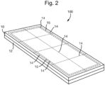
- FIG. 2 is a schematic illustration (not to scale) showing the core assembly 100 produced at step s2.
- the core assembly 100 is produced by applying stopping off material (for example, a yttria stop-off compound) between two core sheets 10, 12.
- the stopping off material forms a layer that prevents the core sheets 10, 12 being diffusion bonded together at operating temperatures in the areas to which the stopping off material has been applied.
- the core sheets 10, 12 are then joined together by line bonds 14.
- These line bonds 14 can be formed by diffusion bonding the two core sheets 10, 12 together, in which case the stopping off material should be omitted in the region of the line bonds 14.
- the core sheets 10, 12 can be bonded together by other techniques, for example resistance welding or laser bonding.
- the line bonds 14 define a plurality of cells which are to be inflated at a later stage, as described in more detail later below with reference to steps s12 and s14, and Figures 6 and 8 .
- the line bonds 14 define a channel 15 (i.e. a so-called "raceway") proximate to, but spaced apart from, the side edges of the core assembly 100.
- the channel 15 surrounds a central portion of the core assembly 100.
- the channel 15 may run approximately parallel to the side edges of the core assembly 100, while also being spaced apart from those side edges.
- the channel 15 is to be inflated at a later stage, as described in more detail later below with reference to steps s12 and s14, and Figures 7 .
- a pack assembly (i.e. a pack) is produced.
- FIG. 3 is a schematic illustration (not to scale) showing the pack assembly 200 produced at step s4.
- the pack assembly 200 is formed by sandwiching the core assembly 100 (i.e. the bonded together core sheets 10, 12) between skin sheets 16, 18.
- the pack assembly 200 shall be sealed around its outer perimeter by a weld or a bond (not shown).
- Ducts are included in the pack assembly 200 allowing gas to be injected into the region between the core sheets 10, 12 and independently in regions between the skin sheets 16, 18 and their adjacent core sheets, 10, 12. Gaps may be left in the line bonds 14 to allow the passage of gas between adjacent regions of the core sheets.
- the core and skin sheets may be titanium alloy sheets, for example titanium/aluminium/vanadium alloy, e.g. alpha-beta titanium alloys such as Ti-6Al-4V.
- the one or more of the core and skin sheets may be a different material capable of being superplastically formed and diffusion bonded, for example a metal selected from the group consisting of nickel, cobalt, titanium, iron, aluminium and alloys thereof and combinations thereof.
- a steel ultra-fine grained steel
- a superalloy for example a nickel or cobalt superalloy
- Particularly preferred alloys are Ti-6Al-4V or SP-700 (Ti-4.5AI-3V-2Mo-2Fe).
- the surfaces of the skin sheets 16, 18 that are adjacent to the core sheets, 10, 12 comprise venting grooves formed therein.
- Figure 4 is a schematic illustration (not to scale) showing a perspective view of the skin sheet 18.
- Figure 5 is a schematic illustration (not to scale) showing a cross section through the skin sheet 18 shown in Figure 4 , along the line indicated X-X in Figure 4 .
- a surface 180 of the skin sheet 18 that is adjacent to (e.g. abutting) the core sheet 12 in the pack assembly 200 (and will later be diffusion bonded to that core sheet 12) comprises venting grooves 182 formed therein.
- the venting grooves 182 are grooves or depressions in the surface 180 of the skin sheet 18.
- the venting grooves 182 may be formed by machining, e.g. using a computer numerical control (CNC) router, the surface 180 of the skin sheet 18.
- CNC computer numerical control
- the venting grooves 182 take the form of a plurality of interlocking or intersecting loops (or loop-shaped grooves). Thus, when viewed from above, the plurality of loops of the venting grooves 182 overlap or intersect each other.
- the loops of the venting grooves 182 may be substantially circular or elliptical loops, but alternatively the venting grooves may have different shapes for example polygonal-loops, or non-loops.
- the loops, or loop-shaped grooves, of the venting grooves 182 may have any appropriate diameters.
- the diameters may be from about 0.1cm to 20cm.
- Examples of appropriate diameters for the loops include, but are not limited to about 0.1cm-5cm, 5cm-10cm, 10cm-15cm, or 15cm-20cm.
- the widths of the venting grooves 182 (an example of which is indicated in Figure 5 by arrows and the reference numeral 184) may be any appropriate widths.
- the widths may be from about 1mm to 10mm.
- Examples of appropriate widths for the venting grooves 182 include, but are not limited to about 1 mm, 2mm, 3mm, 4mm, 5mm, or more than 5mm.
- the depths of the venting grooves 182 may be any appropriate depth.
- the depths may be from about 0.5mm to 1.0mm.
- Examples of appropriate depths for the venting grooves 182 include, but are not limited to about 0.5mm, 0.6mm, 0.7mm, 0.8mm, 0.9mm, 1.0mm, or more than 1 mm.
- the venting grooves 182 define multiple interlocking recessed pathways across the surface 180 of the skin sheet 18.
- the pathways defined by the venting grooves 182 may be meandering, i.e. non-straight (preferably curved), recessed pathways. Nevertheless, in some embodiments, the venting grooves 182 or a portion thereof may define a straight recessed pathway across the surface 180 of the skin sheet 18.
- venting grooves 182 are illustrated in Figures 4 and 5 as comprising nine interlocking loops (or loop-shaped grooves), for reasons of clarity and ease of depiction only. It will be appreciated by those skilled in the art that, in practice, the venting grooves 182 may comprise a different number (e.g. more or less than nine) interlocking loops (or loop-shaped grooves).
- venting grooves 182 are illustrated in Figures 4 and 5 as being formed in only part, not all, of the surface 180 of the skin sheet 18. However, it will be appreciated by those skilled in the art that, in practice, the venting grooves 182 may be formed in a different part of the surface 180 of the skin sheet 18 to that shown in Figures 4 and 5 , or indeed across substantially all of the surface 180.
- the venting grooves 182 are located on the surface 180 at least at a position that is at and/or proximate to the peripheral edge portion of that surface 180.
- the venting grooves 182 are located at and proximate to a portion of the surface 180 that will become the flange of the panel during the later steps (s6-s18) of the process of Figure 2 .
- venting grooves 182 in the skin sheet 18 are described above (with reference to Figures 4 and 5 ), it will be appreciated by those skilled in the art that the other skin sheet 16 may also comprise venting grooves in its surface that is adjacent to (e.g. abutting) the core sheet 10 in the pack assembly 200 (and will later be diffusion bonded to that core sheet 10). Also, venting grooves may be formed in a surface of one or both of the core sheets 10, 12 that is adjacent to (e.g. abutting) a skin sheet 16, 18 in the pack assembly 200.
- Figure 6 is a schematic illustration (not to scale) showing the pack assembly 200 (i.e. the core sheets 10, 12 and skin sheets 16, 18) within a moulding tool 20.
- the pack assembly 200 is placed between two halves of the moulding tool 20 that can be heated.
- the two halves of the moulding tool 20 are pressed together to hold the pack assembly 200 within the internal cavity of the moulding tool 200.
- these edges of the pack assembly are hereinafter referred to as a "flange portion" of the panel, and are indicated in Figure 6 by the reference numeral 201.
- the clamping forces when subsequently supplemented by heating, can provide for the development of diffusion bonds 21 at the flange portion 201 if so desired.
- Ducts are included in the pack assembly 200 and/or the mould tool 20 allowing gas to be injected into regions between the skin sheets 16, 18 and the mould tool 20, at least in the flange portion 201, as described in more detail later below with reference to step s16.
- the moulding tool 20 comprises recessed grooves 202 that, when the pack assembly 200 is placed in the moulding tool 20, engages with the flange portion 201 of the pack assembly, at a position approximately opposite the channel 15.
- these recessed grooves 202 may be omitted.
- the moulding tool 20 with the pack assembly 200 therein is heated to a temperature at which superplastic forming takes place.
- superplasticity takes its usual meaning in the art, that of the ability of a polycrystalline material to exhibit, in a generally isotropic manner, very high tensile elongation prior to failure. Whether superplastic flow has been induced in a material can be measured by any known method in the art, such as the Active Standard ASTM E2448 (standard test method for determining the superplastic properties of metallic sheet materials).
- the temperatures required to induce superplasticity in a particular material are also known in the art. For example in the case of an titanium alloy such as Ti-6% Al-4% V, the required temperature is typically in excess of 850°C (e.g.
- the temperature required to induce superplasticity may be as low as about 450-520°C.
- an inert gas is injected between each skin sheet 16, 18 and its adjacent core sheet 10, 12 respectively.
- inert gas is injected into the cavities 30 between the skin and core sheets.
- This inert gas may be injected into the cavities 30 between the skin and core sheets via a so-called "skin gas line" 203.
- This injection of gas into the cavities 30 causes the skin sheets 16, 18 to be urged against the internal face of the moulding tool 20, as indicated in Figure 4 by arrows and the reference numerals 204.
- the skin sheets 16, 18 thereby adopt the shape of the internal face of the moulding tool 20.
- titanium alloys can form a surface layer (or "case"), which is an alpha phase formed particularly in the presence of alpha phase stabilising elements, such as oxygen and nitrogen.
- alpha phase stabilising elements such as oxygen and nitrogen.
- the gas used in superplastic forming is preferably substantially free of such alpha case stabilising elements and so a high purity gas with a very low content of alpha case stabilising elements (in excess of 99.99% purity) is preferably used.
- the gas may also be passed over or through a reactive "getter" (e.g.
- an inert gas that may be used in the SPF/DB process is argon, which is inert and relatively cheap, however other inert gases may be used, such as helium, neon, krypton, and xenon.
- inert gas is injected between the core sheets 10, 12 causing the areas between the bonds 14 to "inflate". This inflation indicated in Figure 6 by arrows and the reference numerals 206.
- This inert gas may be injected between the core sheets 10, 12 via a so-called “core gas line” 208.
- FIG. 7 which is a schematic illustration showing the inflated core sheets 10, 12
- this inflation of the core sheets 10, 12 is continued until the core sheets 10, 12 form a series of cells 22 divided by walls 24.
- the upper half of each wall 24 is formed by a double-backed section of core sheet 10; likewise, the bottom half of each wall 24 is formed by a double-backed section of core sheet 12.
- the bonds between the two halves of the wall are the line bonds 14 formed in step s2. Inflation of the core structure (i.e. the core sheets 10, 12) thereby produce a cellular array.
- Figure 8 is a schematic illustration (not to scale) showing further details of the flange portion 201, and illustrating this inflation of the channel 15.
- the inflation of the channel 15 is indicated in Figure 8 by arrows and the reference numeral 210.
- the inflation of the channel 15 causes the core sheets 10, 12 to move apart at the channel 15.
- This relative movement of the core sheets 10, 12 at the channel 15 urges the skin sheets 16, 18 against the surface of the mould tool 20 in the proximity of the channel 15.
- the skin sheets 16, 18 are urged into the recessed grooves 202 in the moulding tool 20 as shown in Figure 8 .
- This urging or forcing of the skin sheets 16, 18 against the surface of the mould tool 20 in the proximity of the channel 15 (and preferably into the recessed grooves 202) tends to create a gas tight seal between the skin sheets 16, 18 and the mould tool 20, along the path of the channel 15.
- a back pressure of gas may be maintained in the cavity 30 between the core sheets 10, 12 and the skin sheets 16, 18 during inflation of the cores.
- the magnitude of this back pressure to avoid such buckling may depend on the relative thickness of the core and the skin sheets 10, 12, 16, 18 and the geometry of the cells 22. As described later below, this back pressure may be removed once the cores have been fully formed (or approaching being fully formed) in order to prevent excess gas being trapped between the core sheet 10, 12 and the skin sheet.
- the gas pressure within the cells 22 and heating are maintained for a predetermined time after the cells 22 have been inflated so as to form diffusion bonds 28 between the skin sheets 16, 18 and the adjacent areas of the core sheets 10, 12.
- diffusion bonds 28 are formed between the double-backed sections of the core sheets 10,12 forming the walls 24 and between the outer edges 26 of the outer perimeter of the pack assembly 200 compressed by the two halves of the moulding tool 20.
- step s14 the gas within the cavities 30 between the core sheets 10, 12 and the skin sheets 16, 18 is controlled.
- gas is withdrawn from the cavities 30 as those cavities 30 shrink during inflation of the cells 22.
- a vacuum pump may be connected to the skin gas line 203 and be used to withdraw gas from the cavities 30. This advantageously tends to prevent or oppose the gas being trapped between the core and skin sheets, which would prevent intimate contact between these sheets and so hinder diffusion bonding.
- Gas may be withdrawn from the cavities 30 in the region of the spandrels 32 formed at the top and bottom of the walls 24 between the core sheets and the skin sheets.
- the venting grooves 182 formed in the internal surfaces 180 of the skin sheets 16, 18 tend to improve removal or withdrawal of the gas from the cavities 30 as those cavities 30 shrink during inflation of the cells 22.
- the venting grooves 182 provide a plurality of meandering channels along which gas may flow out of the cavities 30; these channels may remain open (allowing the gas to be removed from the cavities 30), even when the core sheets 10, 12 contact with and bond to the skin sheets 16, 18.
- the improved removal of the gas from the cavities 30 due to the venting grooves 182 advantageously tends to remove the likelihood of pockets of gas being trapped between the core and skin sheets.
- intimate contact between the core and skin sheets tends to be improved, which tends to lead to improved diffusion bonding between these sheets, especially in the regions bounded by the loops of the venting grooves 182.
- an inert gas is injected between the skin sheets 16, 18 and the moulding tool 20, preferably at or proximate to the flange portion 201.
- this gas injection is performed after formation of the diffusion bonds 28 between the skin sheets 16, 18 and the adjacent areas of the core sheets 10, 12.
- FIG 9 is a schematic illustration (not to scale) illustrating an inert gas being injected between the skin sheet 18 and the moulding tool 20 at the flange portion 201, as performed at step s16.
- This inert gas may be injected into the cavities 210 between the skin sheets 16, 18 via a so-called "tool gas line" 212.
- This injection of gas into the cavities 210 tends to cause expansion of these cavities 210, as indicated in Figure 9 by arrows and the reference numeral 214.
- This expansion of the cavities 212 forces the skin sheets 16, 18 towards each other (against the core sheets 10, 12 sandwiched between the skin sheets 16, 18), as indicated in Figure 9 by arrows and the reference numeral 216.
- inert gas is injected, via the tool gas line 212, into a cavity 210 at only one side of the flange portion 201, i.e. either between the upper skin sheet 16 and the moulding tool 20 or between the lower skin sheet 18 and the moulding tool 20. It may be the case that a groove recess 202 is only present at in the moulding tool 20 at which the inert gas is injected.
- inert gas is injected via the tool gas line 212 only between the upper skin sheet 16 and the moulding tool 20 and not between the lower skin sheet 18 and the moulding tool 20, then it may be the gas that there is a groove recess 202 only in the upper part of the moulding tool 20 (adjacent to the upper skin sheet 16), and not the lower part of the moulding tool 20.
- gas tight seal between the skin sheets 16, 18 and the mould tool 20, along the path of the channel 15, created by inflation of the channel 15, tends to prevent or oppose gas from escaping from the cavities 210 between the skin sheets 16, 18 and the mould tool 20.
- the gas injected between the skin sheets 16, 18 and the moulding tool 20 is at a lower pressure than the gas injected between the core sheets 10, 12 (i.e. the gas injected into the cells 22 and channel 15 via the core gas line 208).
- the inert gas is injected between the skin sheets 16, 18 and the moulding tool 20 only at one side of the pack assembly 200, e.g. between one half of the moulding tool 20 and one of the skin sheets 16 or 18, in the flange portion 201. This may cause the pack assembly to be forced against the other half of the mould tool 20, thereby to improve intimate contact between the core and skin sheets 10, 12, 16, 18, which tends to provide improved diffusion bonding between these sheets 10, 12, 16, 18, at least in the flange portion 201.
- step s16 and s16 gas pressure may be removed (e.g. gradually), and the formed structure (i.e. the panel) is cooled and removed from the moulding tool 20.
- the above described method and apparatus tends to reduce the likelihood of gas entrapment between the core and skin sheets 10, 12, 16, 18 of the panel.
- Such trapped gas would tend to reduce the strength of the diffusion bond between the core and skin sheets or indeed can prevent a diffusion bond being formed in those areas where gas is entrapped.
- Gas may be removed from the cavity 30 between the core and skin sheets via the spandrels 32 and the venting grooves 182, which tend to maintain a gas conduit for at least a time after the core cells 22 have been substantially formed.
- venting grooves are in the form of a plurality of interconnected loops.
- the regions within these loops tend to be substantially fully diffusion bonded by the above described process, i.e. having no or innocuous bond defects.
- These fully bonded regions bounded by the loops of the venting groove are particularly well suited as locations for mechanical fasteners due to the lack of inter-laminar no-bonds. Thus, improved mechanical and fatigue properties tend to arise.
- the venting grooves are formed so that selected locations for mechanical fasteners are within regions bounded by the loops of the venting grooves.
- the above described method and apparatus tends to provide for improved strength diffusion bonding between the sheets of the panel, at least in the flange portion.
- a skin sheet is a sheet that is superplastically formed to the internal shape of a mould.
- a core sheet is a sheet that is superplastically formed after the skin sheet and so, while it is being superplastically formed, a cavity exists between the core sheet and its associated skin sheet. Subsequently, the core sheet and the skin sheet are diffusion bonded together. It is possible to have only one skin sheet in the structure; e.g. two core sheets could be provided, one of which is pressed against the skin sheet and diffusion bonded thereto and the other is pressed against the internal surface of the mould, thereby providing an outside surface in which the spandrels are visible.
- a single core sheet can be provided with two skin sheets such that the core sheets zigzags between the two skin sheets; such an arrangement is well known.
- the structure has two core sheets and two skin sheets.
- a greater number of core sheets can be provided, if desired.
Landscapes
- Engineering & Computer Science (AREA)
- Mechanical Engineering (AREA)
- Physics & Mathematics (AREA)
- Fluid Mechanics (AREA)
- Aviation & Aerospace Engineering (AREA)
- Laminated Bodies (AREA)
- Pressure Welding/Diffusion-Bonding (AREA)
- Ceramic Products (AREA)
Claims (13)
- Procédé de formation d'une structure par liaison par diffusion et formage superplastique d'au moins une feuille pelliculaire (16, 18) et d'au moins une feuille centrale (10, 12), le procédé comprenant :a) la formation d'un paquet (200) à partir de l'au moins une feuille pelliculaire (16, 18) et de l'au moins une feuille centrale (10, 12), dans lequel le paquet (200) comprend une première surface de la feuille centrale (10, 12) positionnée adjacente à une seconde surface de la feuille pelliculaire (16, 18), et dans lequel une ou plusieurs rainures de mise à l'air libre (182) sont formées dans au moins une surface choisie dans le groupe de surfaces constitué par la première surface de la feuille centrale (10, 12) et la seconde surface de la feuille pelliculaire (16, 18) ;b) le placement du paquet (200) dans un moule (20) et le chauffage du paquet (200) à une température à laquelle les feuilles peuvent se déformer de manière superplastique ;c) l'injection d'un premier gaz entre la première surface de la feuille centrale (10, 12) et la seconde surface de la feuille pelliculaire (16, 18) pour pousser la feuille pelliculaire (16, 18) contre une face interne du moule (20) en formant de ce fait une cavité (30) entre la première surface de la feuille centrale (10, 12) et la seconde surface de la feuille pelliculaire (16, 18) ;d) l'injection d'un deuxième gaz sur le côté de la feuille centrale (10, 12) à distance de la feuille pelliculaire (16, 18) pour pousser la feuille centrale (10, 12) contre la feuille pelliculaire (16, 18) ;e) le maintien de la pression gazeuse du deuxième gaz sur le côté de la feuille centrale (10, 12) à distance de la feuille pelliculaire (16, 18), formant de ce fait une liaison par diffusion entre la feuille pelliculaire (16, 18) et la feuille centrale (10, 12) ; etf) le retrait d'une partie ou de la totalité du premier gaz de la cavité (30) entre la première surface de la feuille centrale (10, 12) et la seconde surface de la feuille pelliculaire (16, 18) pendant au moins une partie de l'étape d).
- Procédé selon la revendication 1, dans lequel la ou les rainures de mise à l'air libre (182) sont formées dans la seconde surface de la feuille pelliculaire (16, 18) et non dans la première surface de la feuille centrale (10, 12).
- Procédé selon la revendication 1 ou 2, dans lequel la ou les rainures de mise à l'air libre (182) définissent un ou plusieurs trajets sinueux à travers la surface ou les surfaces dans laquelle/lesquelles la ou les rainures de mise à l'air libre (182) sont formées.
- Procédé selon l'une quelconque des revendications 1 à 3, dans lequel la ou les rainures de mise à l'air libre (182) sont formées par usinage de la surface ou des surfaces dans laquelle/lesquelles la ou les rainures de mise à l'air libre (182) sont formées.
- Procédé selon l'une quelconque des revendications 1 à 4, dans lequel la ou les rainures de mise à l'air libre (182) définissent une pluralité de boucles interconnectées.
- Procédé selon la revendication 5, dans lequel les boucles sont des cercles ou des ellipses.
- Procédé selon la revendication 5 ou 6, dans lequel le procédé comprend en outre le placement d'un élément de fixation mécanique à travers la structure formée au niveau d'une position qui est dans une boucle définie par les rainures de mise à l'air libre (182).
- Procédé selon l'une quelconque des revendications 1 à 7, dans lequel la ou les rainures de mise à l'air libre (182) sont situées dans au moins une partie bride (201) de la structure.
- Procédé selon l'une quelconque des revendications 1 à 8, dans lequel le procédé comprend en outre l'injection d'un troisième gaz sur le côté de la feuille pelliculaire (16, 18) à distance de la feuille centrale (10, 12), entre la feuille pelliculaire (16, 18) et le moule (20), pour de ce fait pousser ensemble la feuille pelliculaire (16, 18) et la feuille centrale (10, 12).
- Procédé selon l'une quelconque des revendications 1 à 9, dans lequel le premier gaz est le même type de gaz que le deuxième gaz.
- Procédé selon l'une quelconque des revendications 1 à 10, dans lequel les gaz sont des gaz nobles.
- Procédé selon l'une quelconque des revendications 1 à 11, dans lequel au moins deux feuilles centrales (10, 12) qui ont été jointes l'une à l'autre dans des zones sélectionnées sont utilisées et le deuxième gaz injecté à l'étape d) est injecté entre les au moins deux feuilles centrales (10, 12).
- Procédé selon l'une quelconque des revendications 1 à 12, dans lequel :deux feuilles pelliculaires (16, 18) sont utilisées ;le paquet (200) à l'étape a) est formé en intercalant une ou plusieurs feuilles centrales (10, 12) entre les feuilles pelliculaires (16, 18) ;le premier gaz est injecté à l'étape c) entre chaque feuille pelliculaire (16, 18) et sa feuille centrale (10, 12) adjacente ; et,à l'étape f), le premier gaz est retiré de la cavité entre chaque feuille pelliculaire (16, 18) et sa feuille centrale (10, 12) adjacente.
Applications Claiming Priority (3)
| Application Number | Priority Date | Filing Date | Title |
|---|---|---|---|
| GB1713454.5A GB2565790B (en) | 2017-08-22 | 2017-08-22 | Superplastic forming and diffusion bonding process |
| EP17187301.1A EP3446804A1 (fr) | 2017-08-22 | 2017-08-22 | Formage superplastique et procédé de liaison par diffusion |
| PCT/GB2018/052276 WO2019038516A1 (fr) | 2017-08-22 | 2018-08-10 | Procédé de formation superplastique et de liaison par diffusion |
Publications (2)
| Publication Number | Publication Date |
|---|---|
| EP3672742A1 EP3672742A1 (fr) | 2020-07-01 |
| EP3672742B1 true EP3672742B1 (fr) | 2023-05-24 |
Family
ID=63145137
Family Applications (1)
| Application Number | Title | Priority Date | Filing Date |
|---|---|---|---|
| EP18752616.5A Active EP3672742B1 (fr) | 2017-08-22 | 2018-08-10 | Formage superplastique et procédé de liaison par diffusion |
Country Status (5)
| Country | Link |
|---|---|
| US (1) | US10850317B2 (fr) |
| EP (1) | EP3672742B1 (fr) |
| AU (1) | AU2018319366B2 (fr) |
| ES (1) | ES2947758T3 (fr) |
| WO (1) | WO2019038516A1 (fr) |
Families Citing this family (1)
| Publication number | Priority date | Publication date | Assignee | Title |
|---|---|---|---|---|
| CN111069860B (zh) * | 2019-12-31 | 2022-10-25 | 航天海鹰(哈尔滨)钛业有限公司 | 一种高温合金四层点阵轻量化结构制备方法 |
Family Cites Families (47)
| Publication number | Priority date | Publication date | Assignee | Title |
|---|---|---|---|---|
| US3934441A (en) | 1974-07-08 | 1976-01-27 | Rockwell International Corporation | Controlled environment superplastic forming of metals |
| US4042162A (en) * | 1975-07-11 | 1977-08-16 | General Motors Corporation | Airfoil fabrication |
| US4087037A (en) * | 1976-07-09 | 1978-05-02 | Mcdonnell Douglas Corporation | Method of and tools for producing superplastically formed and diffusion bonded structures |
| US4117970A (en) * | 1976-11-16 | 1978-10-03 | Rockwell International Corporation | Method for fabrication of honeycomb structures |
| US4304821A (en) * | 1978-04-18 | 1981-12-08 | Mcdonnell Douglas Corporation | Method of fabricating metallic sandwich structure |
| US4426032A (en) | 1981-09-10 | 1984-01-17 | The United States Of America As Represented By The Secretary Of The Air Force | Tool sealing arrangement and method |
| US4811890A (en) * | 1983-05-07 | 1989-03-14 | Rockwell International Corporation | Method of eliminating core distortion in diffusion bonded and uperplastically formed structures |
| US4916928A (en) * | 1988-04-28 | 1990-04-17 | Mcdonnell Douglas Corporation | Stops for curved SPF/DB sandwich fabrication |
| GB8821222D0 (en) * | 1988-09-09 | 1988-12-14 | British Aerospace | Double curvature structures by superplastic forming & diffusion bonding |
| US5385204A (en) * | 1989-08-25 | 1995-01-31 | Rolls-Royce Plc | Heat exchanger and methods of manufacture thereof |
| US5118571A (en) | 1990-12-21 | 1992-06-02 | Ltv Aerospace And Defense Company | Structure and method for forming structural components |
| US5204161A (en) * | 1991-06-03 | 1993-04-20 | Mcdonnell Douglas Corporation | Fabrication of panel structure |
| US5366787A (en) * | 1991-06-03 | 1994-11-22 | Mcdonnell Douglas Corporation | Panel structure fabrication |
| US5141146A (en) * | 1991-06-06 | 1992-08-25 | Mcdonnell Douglas Corporation | Fabrication of superplastically formed trusscore structure |
| US5115963A (en) * | 1991-06-10 | 1992-05-26 | Mcdonnell Douglas Corporation | Superplastic forming of panel structures |
| US5240376A (en) * | 1991-07-31 | 1993-08-31 | Mcdonnell Douglas Corporation | SPF/DB hollow core fan blade |
| GB9117546D0 (en) | 1991-08-14 | 1992-02-19 | British Aerospace | Manufacture of structures by diffusion bonding and superplastic forming |
| US5243758A (en) | 1991-12-09 | 1993-09-14 | General Electric Company | Design and processing method for manufacturing hollow airfoils (three-piece concept) |
| JPH05185169A (ja) | 1992-01-10 | 1993-07-27 | Mitsubishi Heavy Ind Ltd | サンドイッチパネルの製作方法 |
| GB9205034D0 (en) * | 1992-03-07 | 1992-04-22 | British Aerospace | Manufacture of components by superplastic forming |
| GB9206850D0 (en) | 1992-03-28 | 1992-05-13 | British Aerospace | Gas injection/exhaustion techniques for superplastically forming components |
| GB9225702D0 (en) * | 1992-12-09 | 1993-02-03 | British Aerospace | Forming of diffusion bonded joints in superplastically formed metal structures |
| GB2289429B (en) * | 1994-05-10 | 1997-01-22 | Rolls Royce Plc | Hollow component manufacture |
| US5687900A (en) * | 1995-03-28 | 1997-11-18 | Mcdonnell Douglas Corporation | Structural panel having a predetermined shape and an associated method for superplastically forming and diffusion bonding the structural panel |
| US5692881A (en) * | 1995-06-08 | 1997-12-02 | United Technologies Corporation | Hollow metallic structure and method of manufacture |
| WO1997027045A2 (fr) | 1996-01-12 | 1997-07-31 | The Boeing Company | Structure metallique de type sandwich a point d'attache integral |
| US5994666A (en) * | 1996-01-12 | 1999-11-30 | The Boeing Company | Multisheet metal sandwich structures |
| US5890285A (en) * | 1996-08-23 | 1999-04-06 | Mcdonnell Douglas Corporation | Method for superplastically forming a structural article |
| US5881459A (en) * | 1996-09-27 | 1999-03-16 | Mcdonnell Douglas Corporation | Pressure communication for superplastically formed, diffusion bonded panels and method of manufacture |
| US5941446A (en) * | 1997-07-10 | 1999-08-24 | Mcdonnell Douglas Corporation | SPF/DB airfoil-shaped structure and method of fabrication thereof |
| US6138898A (en) | 1998-12-22 | 2000-10-31 | The Boeing Company | Corner gap weld pattern for SPF core packs |
| JP4530495B2 (ja) * | 2000-07-03 | 2010-08-25 | 富士重工業株式会社 | 超塑性材料の一体成形方法 |
| GB0130710D0 (en) * | 2001-12-21 | 2002-02-06 | Bae Systems Plc | Superplastic forming and diffusion bonding process |
| FR2834481B1 (fr) | 2002-01-10 | 2004-02-27 | Snecma Moteurs | Procede de fabrication de pieces par soudage par diffusion et par formage superplastique, et moule pour mettre en oeuvre un tel procede |
| GB0203955D0 (en) * | 2002-02-20 | 2002-04-03 | Rolls Royce Plc | A method of manufacturing an article by diffusion bonding and super[lastic forming |
| US7048175B2 (en) | 2003-12-19 | 2006-05-23 | The Boeing Company | Friction welded structural assembly and preform and method for same |
| DE102004001666A1 (de) * | 2004-01-12 | 2005-08-04 | Mtu Aero Engines Gmbh | Verfahren zur Herstellung von Hohlschaufeln |
| US7850058B2 (en) | 2004-03-31 | 2010-12-14 | The Boeing Company | Superplastic forming of titanium assemblies |
| US7210611B2 (en) * | 2004-10-21 | 2007-05-01 | The Boeing Company | Formed structural assembly and associated preform and method |
| US7049548B1 (en) | 2005-03-21 | 2006-05-23 | The Boeing Company | System and method for processing a preform vacuum vessel to produce a structural assembly |
| US7318333B2 (en) | 2005-05-18 | 2008-01-15 | Ford Global Technologies, L.L.C. | Superplastic forming tool |
| RU2412017C2 (ru) * | 2008-12-24 | 2011-02-20 | ОАО "Авиадвигатель" | Способ изготовления полой вентиляторной лопатки |
| GB0904571D0 (en) * | 2009-03-18 | 2009-08-12 | Rolls Royce Plc | A method of manufacturing a component comprising an internal structure |
| US8707747B1 (en) | 2012-12-14 | 2014-04-29 | Rohr, Inc. | Forming a shaped sandwich panel with a die and a pressure vessel |
| FR3034690B1 (fr) | 2015-04-09 | 2017-10-20 | Aurock | Procede de pilotage d'une machine de formage superplastique et machine correspondante |
| US10112229B2 (en) * | 2015-08-17 | 2018-10-30 | The Boeing Company | Apparatus and method for forming three-sheet panels |
| JP6288378B2 (ja) | 2016-01-28 | 2018-03-07 | 新日鐵住金株式会社 | パネル状成形品、車両用ドア、及び、パネル状成形品の製造方法 |
-
2018
- 2018-08-10 ES ES18752616T patent/ES2947758T3/es active Active
- 2018-08-10 WO PCT/GB2018/052276 patent/WO2019038516A1/fr not_active Ceased
- 2018-08-10 US US16/634,927 patent/US10850317B2/en active Active
- 2018-08-10 EP EP18752616.5A patent/EP3672742B1/fr active Active
- 2018-08-10 AU AU2018319366A patent/AU2018319366B2/en active Active
Also Published As
| Publication number | Publication date |
|---|---|
| EP3672742A1 (fr) | 2020-07-01 |
| CA3072027A1 (fr) | 2019-02-28 |
| AU2018319366B2 (en) | 2023-12-14 |
| AU2018319366A1 (en) | 2020-02-20 |
| US10850317B2 (en) | 2020-12-01 |
| ES2947758T3 (es) | 2023-08-18 |
| US20200238359A1 (en) | 2020-07-30 |
| WO2019038516A1 (fr) | 2019-02-28 |
Similar Documents
| Publication | Publication Date | Title |
|---|---|---|
| US6337471B1 (en) | Combined superplastic forming and adhesive bonding | |
| US5941446A (en) | SPF/DB airfoil-shaped structure and method of fabrication thereof | |
| US6571450B2 (en) | Process for the monolithic molding of superplastic material | |
| US4632296A (en) | Forming of stiffened panels | |
| EP3446805A1 (fr) | Formage superplastique et procédé de liaison par diffusion | |
| EP3672742B1 (fr) | Formage superplastique et procédé de liaison par diffusion | |
| EP3672744B1 (fr) | Formage superplastique et procédé de liaison par diffusion | |
| EP3446804A1 (fr) | Formage superplastique et procédé de liaison par diffusion | |
| US7134176B2 (en) | Superplastic forming and diffusion bonding process | |
| CA3072027C (fr) | Procede de formation superplastique et de liaison par diffusion | |
| GB2565791A (en) | Superplastic forming and diffusion bonding process | |
| JP4972292B2 (ja) | 超塑性・拡散接合パネルの成形方法 | |
| GB2565790A (en) | Superplastic forming and diffusion bonding process | |
| JPH11169977A (ja) | 超塑性金属の一体成形方法 | |
| US6299963B1 (en) | Superplastically formed panel | |
| US6704981B2 (en) | Superplastic forming method | |
| RU2268102C1 (ru) | Способ изготовления многослойной конструкции |
Legal Events
| Date | Code | Title | Description |
|---|---|---|---|
| STAA | Information on the status of an ep patent application or granted ep patent |
Free format text: STATUS: UNKNOWN |
|
| STAA | Information on the status of an ep patent application or granted ep patent |
Free format text: STATUS: THE INTERNATIONAL PUBLICATION HAS BEEN MADE |
|
| PUAI | Public reference made under article 153(3) epc to a published international application that has entered the european phase |
Free format text: ORIGINAL CODE: 0009012 |
|
| STAA | Information on the status of an ep patent application or granted ep patent |
Free format text: STATUS: REQUEST FOR EXAMINATION WAS MADE |
|
| 17P | Request for examination filed |
Effective date: 20200204 |
|
| AK | Designated contracting states |
Kind code of ref document: A1 Designated state(s): AL AT BE BG CH CY CZ DE DK EE ES FI FR GB GR HR HU IE IS IT LI LT LU LV MC MK MT NL NO PL PT RO RS SE SI SK SM TR |
|
| AX | Request for extension of the european patent |
Extension state: BA ME |
|
| DAV | Request for validation of the european patent (deleted) | ||
| DAX | Request for extension of the european patent (deleted) | ||
| GRAP | Despatch of communication of intention to grant a patent |
Free format text: ORIGINAL CODE: EPIDOSNIGR1 |
|
| STAA | Information on the status of an ep patent application or granted ep patent |
Free format text: STATUS: GRANT OF PATENT IS INTENDED |
|
| INTG | Intention to grant announced |
Effective date: 20230105 |
|
| GRAS | Grant fee paid |
Free format text: ORIGINAL CODE: EPIDOSNIGR3 |
|
| GRAA | (expected) grant |
Free format text: ORIGINAL CODE: 0009210 |
|
| STAA | Information on the status of an ep patent application or granted ep patent |
Free format text: STATUS: THE PATENT HAS BEEN GRANTED |
|
| RBV | Designated contracting states (corrected) |
Designated state(s): AL AT BE BG CH CY CZ DE DK EE ES FI FR GR HR HU IE IS IT LI LT LU LV MC MK MT NL NO PL PT RO RS SE SI SK SM TR |
|
| AK | Designated contracting states |
Kind code of ref document: B1 Designated state(s): AL AT BE BG CH CY CZ DE DK EE ES FI FR GR HR HU IE IS IT LI LT LU LV MC MK MT NL NO PL PT RO RS SE SI SK SM TR |
|
| REG | Reference to a national code |
Ref country code: CH Ref legal event code: EP |
|
| REG | Reference to a national code |
Ref country code: DE Ref legal event code: R096 Ref document number: 602018050195 Country of ref document: DE |
|
| REG | Reference to a national code |
Ref country code: AT Ref legal event code: REF Ref document number: 1569206 Country of ref document: AT Kind code of ref document: T Effective date: 20230615 |
|
| REG | Reference to a national code |
Ref country code: IE Ref legal event code: FG4D |
|
| REG | Reference to a national code |
Ref country code: ES Ref legal event code: FG2A Ref document number: 2947758 Country of ref document: ES Kind code of ref document: T3 Effective date: 20230818 |
|
| REG | Reference to a national code |
Ref country code: LT Ref legal event code: MG9D |
|
| REG | Reference to a national code |
Ref country code: NL Ref legal event code: MP Effective date: 20230524 |
|
| REG | Reference to a national code |
Ref country code: AT Ref legal event code: MK05 Ref document number: 1569206 Country of ref document: AT Kind code of ref document: T Effective date: 20230524 |
|
| PG25 | Lapsed in a contracting state [announced via postgrant information from national office to epo] |
Ref country code: SE Free format text: LAPSE BECAUSE OF FAILURE TO SUBMIT A TRANSLATION OF THE DESCRIPTION OR TO PAY THE FEE WITHIN THE PRESCRIBED TIME-LIMIT Effective date: 20230524 Ref country code: PT Free format text: LAPSE BECAUSE OF FAILURE TO SUBMIT A TRANSLATION OF THE DESCRIPTION OR TO PAY THE FEE WITHIN THE PRESCRIBED TIME-LIMIT Effective date: 20230925 Ref country code: NO Free format text: LAPSE BECAUSE OF FAILURE TO SUBMIT A TRANSLATION OF THE DESCRIPTION OR TO PAY THE FEE WITHIN THE PRESCRIBED TIME-LIMIT Effective date: 20230824 Ref country code: NL Free format text: LAPSE BECAUSE OF FAILURE TO SUBMIT A TRANSLATION OF THE DESCRIPTION OR TO PAY THE FEE WITHIN THE PRESCRIBED TIME-LIMIT Effective date: 20230524 Ref country code: AT Free format text: LAPSE BECAUSE OF FAILURE TO SUBMIT A TRANSLATION OF THE DESCRIPTION OR TO PAY THE FEE WITHIN THE PRESCRIBED TIME-LIMIT Effective date: 20230524 |
|
| PG25 | Lapsed in a contracting state [announced via postgrant information from national office to epo] |
Ref country code: RS Free format text: LAPSE BECAUSE OF FAILURE TO SUBMIT A TRANSLATION OF THE DESCRIPTION OR TO PAY THE FEE WITHIN THE PRESCRIBED TIME-LIMIT Effective date: 20230524 Ref country code: PL Free format text: LAPSE BECAUSE OF FAILURE TO SUBMIT A TRANSLATION OF THE DESCRIPTION OR TO PAY THE FEE WITHIN THE PRESCRIBED TIME-LIMIT Effective date: 20230524 Ref country code: LV Free format text: LAPSE BECAUSE OF FAILURE TO SUBMIT A TRANSLATION OF THE DESCRIPTION OR TO PAY THE FEE WITHIN THE PRESCRIBED TIME-LIMIT Effective date: 20230524 Ref country code: LT Free format text: LAPSE BECAUSE OF FAILURE TO SUBMIT A TRANSLATION OF THE DESCRIPTION OR TO PAY THE FEE WITHIN THE PRESCRIBED TIME-LIMIT Effective date: 20230524 Ref country code: IS Free format text: LAPSE BECAUSE OF FAILURE TO SUBMIT A TRANSLATION OF THE DESCRIPTION OR TO PAY THE FEE WITHIN THE PRESCRIBED TIME-LIMIT Effective date: 20230924 Ref country code: HR Free format text: LAPSE BECAUSE OF FAILURE TO SUBMIT A TRANSLATION OF THE DESCRIPTION OR TO PAY THE FEE WITHIN THE PRESCRIBED TIME-LIMIT Effective date: 20230524 Ref country code: GR Free format text: LAPSE BECAUSE OF FAILURE TO SUBMIT A TRANSLATION OF THE DESCRIPTION OR TO PAY THE FEE WITHIN THE PRESCRIBED TIME-LIMIT Effective date: 20230825 |
|
| PG25 | Lapsed in a contracting state [announced via postgrant information from national office to epo] |
Ref country code: FI Free format text: LAPSE BECAUSE OF FAILURE TO SUBMIT A TRANSLATION OF THE DESCRIPTION OR TO PAY THE FEE WITHIN THE PRESCRIBED TIME-LIMIT Effective date: 20230524 |
|
| PG25 | Lapsed in a contracting state [announced via postgrant information from national office to epo] |
Ref country code: SK Free format text: LAPSE BECAUSE OF FAILURE TO SUBMIT A TRANSLATION OF THE DESCRIPTION OR TO PAY THE FEE WITHIN THE PRESCRIBED TIME-LIMIT Effective date: 20230524 |
|
| PG25 | Lapsed in a contracting state [announced via postgrant information from national office to epo] |
Ref country code: SM Free format text: LAPSE BECAUSE OF FAILURE TO SUBMIT A TRANSLATION OF THE DESCRIPTION OR TO PAY THE FEE WITHIN THE PRESCRIBED TIME-LIMIT Effective date: 20230524 Ref country code: SK Free format text: LAPSE BECAUSE OF FAILURE TO SUBMIT A TRANSLATION OF THE DESCRIPTION OR TO PAY THE FEE WITHIN THE PRESCRIBED TIME-LIMIT Effective date: 20230524 Ref country code: RO Free format text: LAPSE BECAUSE OF FAILURE TO SUBMIT A TRANSLATION OF THE DESCRIPTION OR TO PAY THE FEE WITHIN THE PRESCRIBED TIME-LIMIT Effective date: 20230524 Ref country code: EE Free format text: LAPSE BECAUSE OF FAILURE TO SUBMIT A TRANSLATION OF THE DESCRIPTION OR TO PAY THE FEE WITHIN THE PRESCRIBED TIME-LIMIT Effective date: 20230524 Ref country code: DK Free format text: LAPSE BECAUSE OF FAILURE TO SUBMIT A TRANSLATION OF THE DESCRIPTION OR TO PAY THE FEE WITHIN THE PRESCRIBED TIME-LIMIT Effective date: 20230524 Ref country code: CZ Free format text: LAPSE BECAUSE OF FAILURE TO SUBMIT A TRANSLATION OF THE DESCRIPTION OR TO PAY THE FEE WITHIN THE PRESCRIBED TIME-LIMIT Effective date: 20230524 |
|
| REG | Reference to a national code |
Ref country code: DE Ref legal event code: R097 Ref document number: 602018050195 Country of ref document: DE |
|
| PG25 | Lapsed in a contracting state [announced via postgrant information from national office to epo] |
Ref country code: MC Free format text: LAPSE BECAUSE OF FAILURE TO SUBMIT A TRANSLATION OF THE DESCRIPTION OR TO PAY THE FEE WITHIN THE PRESCRIBED TIME-LIMIT Effective date: 20230524 |
|
| REG | Reference to a national code |
Ref country code: CH Ref legal event code: PL |
|
| PG25 | Lapsed in a contracting state [announced via postgrant information from national office to epo] |
Ref country code: MC Free format text: LAPSE BECAUSE OF FAILURE TO SUBMIT A TRANSLATION OF THE DESCRIPTION OR TO PAY THE FEE WITHIN THE PRESCRIBED TIME-LIMIT Effective date: 20230524 |
|
| PLBE | No opposition filed within time limit |
Free format text: ORIGINAL CODE: 0009261 |
|
| STAA | Information on the status of an ep patent application or granted ep patent |
Free format text: STATUS: NO OPPOSITION FILED WITHIN TIME LIMIT |
|
| PG25 | Lapsed in a contracting state [announced via postgrant information from national office to epo] |
Ref country code: LU Free format text: LAPSE BECAUSE OF NON-PAYMENT OF DUE FEES Effective date: 20230810 |
|
| PG25 | Lapsed in a contracting state [announced via postgrant information from national office to epo] |
Ref country code: LU Free format text: LAPSE BECAUSE OF NON-PAYMENT OF DUE FEES Effective date: 20230810 Ref country code: CH Free format text: LAPSE BECAUSE OF NON-PAYMENT OF DUE FEES Effective date: 20230831 |
|
| 26N | No opposition filed |
Effective date: 20240227 |
|
| PG25 | Lapsed in a contracting state [announced via postgrant information from national office to epo] |
Ref country code: SI Free format text: LAPSE BECAUSE OF FAILURE TO SUBMIT A TRANSLATION OF THE DESCRIPTION OR TO PAY THE FEE WITHIN THE PRESCRIBED TIME-LIMIT Effective date: 20230524 |
|
| REG | Reference to a national code |
Ref country code: BE Ref legal event code: MM Effective date: 20230831 |
|
| REG | Reference to a national code |
Ref country code: IE Ref legal event code: MM4A |
|
| PG25 | Lapsed in a contracting state [announced via postgrant information from national office to epo] |
Ref country code: SI Free format text: LAPSE BECAUSE OF FAILURE TO SUBMIT A TRANSLATION OF THE DESCRIPTION OR TO PAY THE FEE WITHIN THE PRESCRIBED TIME-LIMIT Effective date: 20230524 |
|
| PG25 | Lapsed in a contracting state [announced via postgrant information from national office to epo] |
Ref country code: IE Free format text: LAPSE BECAUSE OF NON-PAYMENT OF DUE FEES Effective date: 20230810 |
|
| PG25 | Lapsed in a contracting state [announced via postgrant information from national office to epo] |
Ref country code: IE Free format text: LAPSE BECAUSE OF NON-PAYMENT OF DUE FEES Effective date: 20230810 |
|
| PG25 | Lapsed in a contracting state [announced via postgrant information from national office to epo] |
Ref country code: BE Free format text: LAPSE BECAUSE OF NON-PAYMENT OF DUE FEES Effective date: 20230831 |
|
| PG25 | Lapsed in a contracting state [announced via postgrant information from national office to epo] |
Ref country code: BG Free format text: LAPSE BECAUSE OF FAILURE TO SUBMIT A TRANSLATION OF THE DESCRIPTION OR TO PAY THE FEE WITHIN THE PRESCRIBED TIME-LIMIT Effective date: 20230524 |
|
| PG25 | Lapsed in a contracting state [announced via postgrant information from national office to epo] |
Ref country code: BG Free format text: LAPSE BECAUSE OF FAILURE TO SUBMIT A TRANSLATION OF THE DESCRIPTION OR TO PAY THE FEE WITHIN THE PRESCRIBED TIME-LIMIT Effective date: 20230524 |
|
| PG25 | Lapsed in a contracting state [announced via postgrant information from national office to epo] |
Ref country code: CY Free format text: LAPSE BECAUSE OF FAILURE TO SUBMIT A TRANSLATION OF THE DESCRIPTION OR TO PAY THE FEE WITHIN THE PRESCRIBED TIME-LIMIT; INVALID AB INITIO Effective date: 20180810 |
|
| PG25 | Lapsed in a contracting state [announced via postgrant information from national office to epo] |
Ref country code: HU Free format text: LAPSE BECAUSE OF FAILURE TO SUBMIT A TRANSLATION OF THE DESCRIPTION OR TO PAY THE FEE WITHIN THE PRESCRIBED TIME-LIMIT; INVALID AB INITIO Effective date: 20180810 |
|
| PGFP | Annual fee paid to national office [announced via postgrant information from national office to epo] |
Ref country code: ES Payment date: 20250901 Year of fee payment: 8 |
|
| PGFP | Annual fee paid to national office [announced via postgrant information from national office to epo] |
Ref country code: DE Payment date: 20250724 Year of fee payment: 8 |
|
| PGFP | Annual fee paid to national office [announced via postgrant information from national office to epo] |
Ref country code: TR Payment date: 20250725 Year of fee payment: 8 Ref country code: IT Payment date: 20250723 Year of fee payment: 8 |
|
| PGFP | Annual fee paid to national office [announced via postgrant information from national office to epo] |
Ref country code: FR Payment date: 20250725 Year of fee payment: 8 |