EP3672818B1 - Pièce de recouvrement conçue pour un élément de train roulant d'un véhicule automobile - Google Patents
Pièce de recouvrement conçue pour un élément de train roulant d'un véhicule automobile Download PDFInfo
- Publication number
- EP3672818B1 EP3672818B1 EP18749757.3A EP18749757A EP3672818B1 EP 3672818 B1 EP3672818 B1 EP 3672818B1 EP 18749757 A EP18749757 A EP 18749757A EP 3672818 B1 EP3672818 B1 EP 3672818B1
- Authority
- EP
- European Patent Office
- Prior art keywords
- covering element
- fastening
- opening
- cover
- flap
- Prior art date
- Legal status (The legal status is an assumption and is not a legal conclusion. Google has not performed a legal analysis and makes no representation as to the accuracy of the status listed.)
- Not-in-force
Links
Images

Classifications
-
- B—PERFORMING OPERATIONS; TRANSPORTING
- B62—LAND VEHICLES FOR TRAVELLING OTHERWISE THAN ON RAILS
- B62D—MOTOR VEHICLES; TRAILERS
- B62D35/00—Vehicle bodies characterised by streamlining
- B62D35/02—Streamlining the undersurfaces
-
- B—PERFORMING OPERATIONS; TRANSPORTING
- B60—VEHICLES IN GENERAL
- B60G—VEHICLE SUSPENSION ARRANGEMENTS
- B60G7/00—Pivoted suspension arms; Accessories thereof
- B60G7/001—Suspension arms, e.g. constructional features
-
- B—PERFORMING OPERATIONS; TRANSPORTING
- B60—VEHICLES IN GENERAL
- B60G—VEHICLE SUSPENSION ARRANGEMENTS
- B60G2204/00—Indexing codes related to suspensions per se or to auxiliary parts
-
- B—PERFORMING OPERATIONS; TRANSPORTING
- B60—VEHICLES IN GENERAL
- B60G—VEHICLE SUSPENSION ARRANGEMENTS
- B60G2204/00—Indexing codes related to suspensions per se or to auxiliary parts
- B60G2204/10—Mounting of suspension elements
- B60G2204/20—Mounting of accessories, e.g. pump, compressor
-
- B—PERFORMING OPERATIONS; TRANSPORTING
- B60—VEHICLES IN GENERAL
- B60G—VEHICLE SUSPENSION ARRANGEMENTS
- B60G2204/00—Indexing codes related to suspensions per se or to auxiliary parts
- B60G2204/40—Auxiliary suspension parts; Adjustment of suspensions
- B60G2204/43—Fittings, brackets or knuckles
- B60G2204/4308—Protecting guards, e.g. for rigid axle damage protection
-
- B—PERFORMING OPERATIONS; TRANSPORTING
- B60—VEHICLES IN GENERAL
- B60G—VEHICLE SUSPENSION ARRANGEMENTS
- B60G2206/00—Indexing codes related to the manufacturing of suspensions: constructional features, the materials used, procedures or tools
- B60G2206/01—Constructional features of suspension elements, e.g. arms, dampers, springs
- B60G2206/10—Constructional features of arms
- B60G2206/11—Constructional features of arms the arm being a radius or track or torque or steering rod or stabiliser end link
-
- B—PERFORMING OPERATIONS; TRANSPORTING
- B60—VEHICLES IN GENERAL
- B60G—VEHICLE SUSPENSION ARRANGEMENTS
- B60G2206/00—Indexing codes related to the manufacturing of suspensions: constructional features, the materials used, procedures or tools
- B60G2206/01—Constructional features of suspension elements, e.g. arms, dampers, springs
- B60G2206/80—Manufacturing procedures
- B60G2206/82—Joining
-
- Y—GENERAL TAGGING OF NEW TECHNOLOGICAL DEVELOPMENTS; GENERAL TAGGING OF CROSS-SECTIONAL TECHNOLOGIES SPANNING OVER SEVERAL SECTIONS OF THE IPC; TECHNICAL SUBJECTS COVERED BY FORMER USPC CROSS-REFERENCE ART COLLECTIONS [XRACs] AND DIGESTS
- Y02—TECHNOLOGIES OR APPLICATIONS FOR MITIGATION OR ADAPTATION AGAINST CLIMATE CHANGE
- Y02T—CLIMATE CHANGE MITIGATION TECHNOLOGIES RELATED TO TRANSPORTATION
- Y02T10/00—Road transport of goods or passengers
- Y02T10/80—Technologies aiming to reduce greenhouse gasses emissions common to all road transportation technologies
- Y02T10/82—Elements for improving aerodynamics
-
- Y—GENERAL TAGGING OF NEW TECHNOLOGICAL DEVELOPMENTS; GENERAL TAGGING OF CROSS-SECTIONAL TECHNOLOGIES SPANNING OVER SEVERAL SECTIONS OF THE IPC; TECHNICAL SUBJECTS COVERED BY FORMER USPC CROSS-REFERENCE ART COLLECTIONS [XRACs] AND DIGESTS
- Y02—TECHNOLOGIES OR APPLICATIONS FOR MITIGATION OR ADAPTATION AGAINST CLIMATE CHANGE
- Y02T—CLIMATE CHANGE MITIGATION TECHNOLOGIES RELATED TO TRANSPORTATION
- Y02T10/00—Road transport of goods or passengers
- Y02T10/80—Technologies aiming to reduce greenhouse gasses emissions common to all road transportation technologies
- Y02T10/88—Optimized components or subsystems, e.g. lighting, actively controlled glasses
Definitions
- the invention relates to a cover part for a chassis control arm of a motor vehicle according to the type specified in the preamble of patent claim 1.
- the area of the wheel suspension and the underside of a motor vehicle are aerodynamic problem areas.
- Both the underside of modern motor vehicles and the chassis control arms, which form part of the wheel suspension, are partially provided with specially designed covers to achieve better airflow around the underbody and the wheels. Improved aerodynamics reduce, among other things, the consumption of a motor vehicle and the noise level.
- the covers also ensure protection against stone chips and damage when driving over obstacles.
- the U.S. 7,654,544 a cover part for a chassis control arm with a hollow profile that is open at the bottom.
- the pi-shaped cross-section of the chassis control arm enables the cover part to be attached to the outer sides of the control arm with a positive and non-positive fit.
- the DE 10 2013 006 253 A1 discloses a cover for a chassis control arm, which has a receptacle for a fastener designed as a rivet or screw.
- the screwing of the cover allows, for example, detachable attachment to the suspension link.
- a metallic sleeve forms the mount. The ends of the sleeve can be crimped to secure the sleeve in the receptacle.
- the invention is based on the object of further developing a cover for a chassis control arm according to the type specified in the preamble of patent claim 1 that ensures simple and captive assembly of the cover.
- a covering element for a chassis link comprises a covering surface with a first and second attachment section, which extend from the covering surface towards the chassis link, as well as a wall that is pulled up towards the front in the direction of travel.
- the distal attachment sections and the suspension link have receptacles for fasteners, by means of which the cover element is attached to the underside of the suspension link.
- the wall which is raised in the direction of travel, serves to increase aerodynamics and also protects against stone chips. However, it restricts the accessibility to the suspension arm and to the fastening section, so that the fastening means can only be attached on one side.
- the cover element has at least one opening that allows access to the fastening section.
- the opening formed in the cover element is arranged in the intermediate space between the two fastening sections, the fastening sections being designed to extend from the surface of the cover element towards the suspension arm and being arranged in such a way that in the installed state they each extend in the longitudinal direction of the suspension arm on one of the webs of the suspension arm.
- the design of the cover element according to the invention enables easy access to the distal fastening sections by means of the opening. In particular, access to the web pointing forward in the direction of travel, which is otherwise inaccessible due to the raised wall, is also guaranteed.
- This embodiment of the invention ensures not only a particularly simple but also a captive assembly of the cover element. Another advantage is the higher degree of freedom in the axial and lateral adjustment of the cover, so that a shape of the cover to different suspension arms with different geometries, z. B. different widths can be mounted.
- a further advantage is that access to the two attachment sections is ensured in a particularly simple manner.
- the opening of the cover element is preferably designed as a rectangle. This embodiment not only enables particularly easy access to the opening, but also offers the possibility of using each side of the rectangle to form a hinge.
- a preferred embodiment of the invention provides that the opening in the cover can be closed by means of a flap. This not only ensures the aerodynamics of the cover part, but also protects the chassis link from damage over the entire length of the cover.
- the flap is preferably designed as an integral part of the cover element, with the entire cover element preferably being made of plastic.
- the advantages of this embodiment are not only easier handling of an individual element, but also very simple and inexpensive production, for example as a one-piece injection molded part. Another advantage is that the flap is securely fastened and cannot be lost.
- the flap is preferably integrated in the cover element by means of a film hinge made of the same material.
- a film hinge made of the same material.
- Film hinges enable the easy production of complete parts in e.g. B. a single injection molding process. It is conceivable that the flap can be fixed to the opening by means of one or more locking mechanisms.
- this embodiment of the invention enables particularly simple handling and assembly. Other benefits of this embodiment are reduction the number of individual parts, the simplified logistics, the guaranteed security against loss and the reduced time required for installation and removal during assembly.
- first and the second fastening section are spaced apart from one another transversely to the longitudinal direction of the handlebar, so that they are arranged on more or less parallel planes to one another, the opening being formed in the intermediate space between the two fastening sections.
- both webs can advantageously serve as connection points for the cover element to the chassis control arm.
- Both the attachment sections and the webs of the suspension arm have receptacles for attachment means. It can be attached, for example, by means of mounting clips, which are an inexpensive variant and ensure easy handling.
- the advantage of this embodiment is not only the very simple installation of the cover element, but also the attachment to both webs of the chassis control arm, which ensures captive installation.
- the simple geometry of the distal attachment sections enables increased axial and lateral freedom when installing the cover element.
- the advantage is a variable adjustment of the cover element to different variants of a chassis control arm, e.g. B. with different widths.
- the cover element, the flap and the attachment portions are formed from a single pressing, e.g. B. as a one-piece injection molded part.
- a single pressing e.g. B.
- the advantages of an integral design of the cover element are the simple and inexpensive production, the easier handling of the parts during logistics and assembly, and the good and captive strengthening of the one-piece element, especially on rough roads.
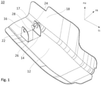
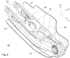
- FIGS 1 to 3 show a schematic representation of a covering element for a chassis control arm 19, which is denoted overall by the reference numeral 10.
- the cover element 10 comprises a substantially horizontal cover surface 12, an opening 14 and at least one first fastening section 16, which is formed upwards from the cover surface 12 in the vehicle vertical direction FH.
- a second fastening section 17 is formed, which is also accessible via the opening 14 .
- the first attachment section 16 and the second attachment section 17 are spaced transversely to the longitudinal direction LL of the handlebar and extend in the longitudinal direction LL of the handlebar.
- the cover is designed with a raised wall 18 in the direction of travel FR, which impairs access to the second fastening section 17 .
- the two fastening sections 16, 17 extend along the webs 20 of the suspension arm 19.
- the fastening sections 16, 17 can extend on the inside and/or on the outside of the webs 20.
- Both the attachment sections 16, 17 and the webs 20 of the suspension arm 19 have receptacles 22 for fasteners.
- the cover element 10 is fastened to the web 20 of the chassis control arm 19 by means of a mounting clip 24 .
- the opening 14 of the cover element 10 is advantageously positioned between the first fastening section 16 and the second fastening section 17, thereby enabling easy access to both distal fastening sections 16, 17.
- the cover element 10 is preferably made of plastic and preferably has a rectangular opening 14 which can be closed by means of a flap 26 is.
- the flap 26 can be fixed to the opening 14 by means of a latching mechanism, which is not shown here for reasons of clarity.
- the flap 26 and the cover element 10 are preferably designed as an integral part, the flap 26 being captively integrated in the cover part 10 by means of a film hinge 28 made of the same material.
Landscapes
- Engineering & Computer Science (AREA)
- Mechanical Engineering (AREA)
- Chemical & Material Sciences (AREA)
- Combustion & Propulsion (AREA)
- Transportation (AREA)
- Fluid-Damping Devices (AREA)
- Connection Of Plates (AREA)
- Body Structure For Vehicles (AREA)
- Vehicle Body Suspensions (AREA)
Claims (9)
- Élément de recouvrement (10) pour un bras de suspension de train roulant (19) d'un véhicule automobile, comprenant une surface de recouvrement (12) qui recouvre au moins une partie de l'élément de train roulant, ainsi qu'une première section de fixation (16) et une seconde section de fixation (17), dans lequel les sections de fixation (16, 17) présentent chacune un logement (22) pour un moyen de fixation (24), dans lequel l'élément de recouvrement (10) présente au moins une ouverture (14) par l'intermédiaire de laquelle la première section de fixation (16) est accessible, caractérisé en ce que,
les sections de fixation (16, 17) sont réalisées pour s'étendre dans la direction de hauteur de véhicule (FH) et dans la direction longitudinale de train roulant (LL) et sont agencées l'une en face de l'autre à une distance transversalement par rapport à la direction longitudinale de train roulant (LL), et en ce que l'ouverture (14) est agencée dans l'espace intermédiaire entre les deux éléments de fixation (16, 17) agencés l'un en face de l'autre. - Élément de recouvrement (10) selon la revendication 1, caractérisé en ce que, l'ouverture (14) présente une forme rectangulaire.
- Élément de recouvrement (10) selon la revendication 1 ou 2, caractérisé en ce que, l'ouverture (14) peut être fermée au moyen d'un clapet (26).
- Élément de recouvrement (10) selon la revendication 3, caractérisé en ce que, le clapet (26) est réalisé comme partie intégrante de l'élément de recouvrement (10).
- Élément de recouvrement (10) selon la revendication 4, caractérisé en ce que, le clapet (26) est intégré dans l'élément de recouvrement (10) au moyen d'un film charnière (28) fait du même matériau.
- Élément de recouvrement (10) selon la revendication 1, dans lequel le bras de suspension de train roulant (19) est réalisé pour présenter deux branches (20), caractérisé en ce que,
à l'état monté, les sections de fixation (16, 17) sont agencées sur le côté extérieur des branches (20) ou sur le côté intérieur des branches (20). - Élément de recouvrement (10) selon l'une quelconque des revendications précédentes, caractérisé en ce que
plusieurs ouvertures (14) avec des première et seconde sections de fixation (16, 17) associées s'étendent dans la direction longitudinale de train roulant (LL). - Élément de recouvrement (10) selon l'une quelconque des revendications précédentes, caractérisé en ce que
la longueur de l'ouverture (14) ou la longueur des ouvertures (14) ainsi que la longueur de la première section de fixation (16) et de la seconde section de fixation (17) sont variables. - Élément de recouvrement (10) selon l'une quelconque des revendications précédentes, caractérisé en ce que
l'élément de recouvrement (10), le clapet (26) et la ou les section(s) de fixation (17) sont réalisés sous la forme d'une pièce moulée par compression monobloc.
Applications Claiming Priority (2)
| Application Number | Priority Date | Filing Date | Title |
|---|---|---|---|
| DE102017214492.0A DE102017214492A1 (de) | 2017-08-21 | 2017-08-21 | Abdeckteil für ein Fahrwerkselement eines Kraftfahrzeugs |
| PCT/EP2018/070448 WO2019038025A1 (fr) | 2017-08-21 | 2018-07-27 | Pièce de recouvrement conçue pour un élément de train roulant d'un véhicule automobile |
Publications (2)
| Publication Number | Publication Date |
|---|---|
| EP3672818A1 EP3672818A1 (fr) | 2020-07-01 |
| EP3672818B1 true EP3672818B1 (fr) | 2022-01-26 |
Family
ID=63103923
Family Applications (1)
| Application Number | Title | Priority Date | Filing Date |
|---|---|---|---|
| EP18749757.3A Not-in-force EP3672818B1 (fr) | 2017-08-21 | 2018-07-27 | Pièce de recouvrement conçue pour un élément de train roulant d'un véhicule automobile |
Country Status (5)
| Country | Link |
|---|---|
| US (1) | US20210078652A1 (fr) |
| EP (1) | EP3672818B1 (fr) |
| CN (1) | CN111032375A (fr) |
| DE (1) | DE102017214492A1 (fr) |
| WO (1) | WO2019038025A1 (fr) |
Families Citing this family (6)
| Publication number | Priority date | Publication date | Assignee | Title |
|---|---|---|---|---|
| DE102020212778B4 (de) * | 2020-10-09 | 2025-09-25 | Zf Friedrichshafen Ag | Fahrwerkbauteil mit mindestens einem Verbindungsabschnitt zum Verbinden mit einem Befestigungsabschnitt eines Fahrwerkelements |
| EP4288328A4 (fr) * | 2021-02-08 | 2024-12-18 | Xtravel Suspension, LLC | Plaque de protection flottante pour véhicule |
| JP2023061815A (ja) * | 2021-10-20 | 2023-05-02 | 本田技研工業株式会社 | サスペンション装置 |
| US12037051B2 (en) * | 2022-03-28 | 2024-07-16 | Honda Motor Co., Ltd. | Flexible inner fender undercover |
| US12091091B2 (en) * | 2022-03-29 | 2024-09-17 | Honda Motor Co., Ltd. | Disk inner fender undercover |
| CN116001509B (zh) * | 2022-11-08 | 2023-09-19 | 江苏克瑞迪机车有限公司 | 一种便于调节的全地形车辆用的悬架及使用方法 |
Family Cites Families (9)
| Publication number | Priority date | Publication date | Assignee | Title |
|---|---|---|---|---|
| JP3151350B2 (ja) * | 1994-01-28 | 2001-04-03 | 株式会社モルテン | トレーリングアームの保護部材 |
| US7654544B2 (en) | 2005-11-02 | 2010-02-02 | Chrysler Group Llc | Air deflector arrangement for a vehicle |
| JP5235220B2 (ja) * | 2011-01-18 | 2013-07-10 | 本田技研工業株式会社 | 車両の空気整流カバー |
| DE102011052175A1 (de) * | 2011-07-27 | 2013-01-31 | Dr. Ing. H.C. F. Porsche Aktiengesellschaft | Luftleitvorrichtung für ein Kraftfahrzeug und Lenkeranordnung mit einer solchen Luftleitvorrichtung |
| US8500149B1 (en) * | 2012-08-06 | 2013-08-06 | Honda Motor Co., Ltd. | Control arm assembly |
| DE102013006253A1 (de) | 2013-04-11 | 2014-10-16 | Audi Ag | Verfahren zur Herstellung einer Luftleiteinrichtung für einen Fahrwerkslenker und Fahrwerkslenker mit einer Luftleiteinrichtung |
| DE102014003305A1 (de) | 2014-03-08 | 2015-09-10 | Audi Ag | Abdeckung für einen Fahrwerkslenker |
| KR102253159B1 (ko) * | 2014-11-21 | 2021-05-18 | 현대모비스 주식회사 | 차량의 서스펜션 로어암 |
| JP6308196B2 (ja) * | 2015-11-06 | 2018-04-11 | マツダ株式会社 | 自動車の後部整流構造 |
-
2017
- 2017-08-21 DE DE102017214492.0A patent/DE102017214492A1/de not_active Withdrawn
-
2018
- 2018-07-27 CN CN201880053535.1A patent/CN111032375A/zh not_active Withdrawn
- 2018-07-27 US US16/629,685 patent/US20210078652A1/en not_active Abandoned
- 2018-07-27 WO PCT/EP2018/070448 patent/WO2019038025A1/fr not_active Ceased
- 2018-07-27 EP EP18749757.3A patent/EP3672818B1/fr not_active Not-in-force
Also Published As
| Publication number | Publication date |
|---|---|
| US20210078652A1 (en) | 2021-03-18 |
| DE102017214492A1 (de) | 2019-02-21 |
| WO2019038025A1 (fr) | 2019-02-28 |
| CN111032375A (zh) | 2020-04-17 |
| EP3672818A1 (fr) | 2020-07-01 |
Similar Documents
| Publication | Publication Date | Title |
|---|---|---|
| WO2019038025A1 (fr) | Pièce de recouvrement conçue pour un élément de train roulant d'un véhicule automobile | |
| EP3003835B1 (fr) | Véhicule automobile muni d'un conduit d'air sortant d'un passage de roue | |
| EP3116767B1 (fr) | Recouvrement pour un bras de suspension de train de roulement | |
| DE102017111870B4 (de) | Fahrzeugunterstruktur | |
| EP2789527B2 (fr) | Procédé de fabrication d'un dispositif de guidage d'air pour un bras de suspension et bras de suspension doté d'un dispositif de guidage d'air | |
| EP1612127B1 (fr) | Véhicule automobile avec un coffre | |
| EP1088746A2 (fr) | Module de toit véhiculaire avec ensemble de toit coulissant intégré | |
| DE112016003817T5 (de) | Deflektorstruktur eines Personenkraftwagens | |
| WO2015082149A1 (fr) | Habillage de dessous de caisse pour un véhicule automobile à deux voies ainsi que véhicule automobile à deux voies doté d'un tel habillage de dessous de caisse | |
| DE102015109698B4 (de) | Kühlsystem für ein Fahrzeug | |
| EP2974945B1 (fr) | Rabat pour un véhicule | |
| WO2005056344A2 (fr) | Element structurel d'un assemblage pare-chocs d'un vehicule | |
| DE102012022899A1 (de) | Verbindungselement zur Abstützung eines Stoßfängers eines Kraftfahrzeuges gegenüber einem Montageträger, Baueinheit mit einem solchen Verbindungselement sowie Verfahren zur Herstellung eines Verbindungselements | |
| DE102013021142A1 (de) | Sensorträger zur Halterung einer Sensorelektrode eines kapazitiven Sensors an einem Kraftfahrzeug sowie Montageverfahren für einen solchen Sensorträger | |
| EP3141408A1 (fr) | Bielle de poussee de roue pour un vehicule automobile | |
| DE102016113730A1 (de) | Querträger im Kraftfahrzeug | |
| EP0332846B1 (fr) | Grille de radiateur pour véhicules à moteur | |
| DE102008033694A1 (de) | Gassackmodul mit einem Gassack, insbesondere einem Kopf-Seitengassack | |
| DE60311717T2 (de) | Schiebedachanordnung für ein Fahrzeug | |
| DE202009012430U1 (de) | Grundträger | |
| DE102016116701B4 (de) | Seitenbauteil und Fahrzeug mit einem Seitenbauteil | |
| EP1060934B1 (fr) | Véhicule avec entrée de passage d'air | |
| DE102016006845A1 (de) | Verbindung von Außenverkleidungsbauteilen einer Kraftfahrzeugkarosserie | |
| DE102015217654B4 (de) | Anordnung eines Frontspoilers an einem Montageträger für ein Kühlermodul in einem Vorderwagen eines Kraftfahrzeuges | |
| DE102019218512A1 (de) | Luftleitelement |
Legal Events
| Date | Code | Title | Description |
|---|---|---|---|
| STAA | Information on the status of an ep patent application or granted ep patent |
Free format text: STATUS: UNKNOWN |
|
| STAA | Information on the status of an ep patent application or granted ep patent |
Free format text: STATUS: THE INTERNATIONAL PUBLICATION HAS BEEN MADE |
|
| PUAI | Public reference made under article 153(3) epc to a published international application that has entered the european phase |
Free format text: ORIGINAL CODE: 0009012 |
|
| STAA | Information on the status of an ep patent application or granted ep patent |
Free format text: STATUS: REQUEST FOR EXAMINATION WAS MADE |
|
| 17P | Request for examination filed |
Effective date: 20200323 |
|
| AK | Designated contracting states |
Kind code of ref document: A1 Designated state(s): AL AT BE BG CH CY CZ DE DK EE ES FI FR GB GR HR HU IE IS IT LI LT LU LV MC MK MT NL NO PL PT RO RS SE SI SK SM TR |
|
| AX | Request for extension of the european patent |
Extension state: BA ME |
|
| DAV | Request for validation of the european patent (deleted) | ||
| DAX | Request for extension of the european patent (deleted) | ||
| STAA | Information on the status of an ep patent application or granted ep patent |
Free format text: STATUS: EXAMINATION IS IN PROGRESS |
|
| 17Q | First examination report despatched |
Effective date: 20210324 |
|
| RIC1 | Information provided on ipc code assigned before grant |
Ipc: B60G 7/00 20060101AFI20210721BHEP Ipc: B62D 35/02 20060101ALI20210721BHEP |
|
| GRAP | Despatch of communication of intention to grant a patent |
Free format text: ORIGINAL CODE: EPIDOSNIGR1 |
|
| STAA | Information on the status of an ep patent application or granted ep patent |
Free format text: STATUS: GRANT OF PATENT IS INTENDED |
|
| INTG | Intention to grant announced |
Effective date: 20210915 |
|
| GRAS | Grant fee paid |
Free format text: ORIGINAL CODE: EPIDOSNIGR3 |
|
| GRAA | (expected) grant |
Free format text: ORIGINAL CODE: 0009210 |
|
| STAA | Information on the status of an ep patent application or granted ep patent |
Free format text: STATUS: THE PATENT HAS BEEN GRANTED |
|
| AK | Designated contracting states |
Kind code of ref document: B1 Designated state(s): AL AT BE BG CH CY CZ DE DK EE ES FI FR GB GR HR HU IE IS IT LI LT LU LV MC MK MT NL NO PL PT RO RS SE SI SK SM TR |
|
| REG | Reference to a national code |
Ref country code: GB Ref legal event code: FG4D Free format text: NOT ENGLISH |
|
| REG | Reference to a national code |
Ref country code: CH Ref legal event code: EP |
|
| REG | Reference to a national code |
Ref country code: AT Ref legal event code: REF Ref document number: 1465001 Country of ref document: AT Kind code of ref document: T Effective date: 20220215 |
|
| REG | Reference to a national code |
Ref country code: IE Ref legal event code: FG4D Free format text: LANGUAGE OF EP DOCUMENT: GERMAN |
|
| REG | Reference to a national code |
Ref country code: DE Ref legal event code: R096 Ref document number: 502018008660 Country of ref document: DE |
|
| REG | Reference to a national code |
Ref country code: LT Ref legal event code: MG9D |
|
| REG | Reference to a national code |
Ref country code: NL Ref legal event code: MP Effective date: 20220126 |
|
| PG25 | Lapsed in a contracting state [announced via postgrant information from national office to epo] |
Ref country code: NL Free format text: LAPSE BECAUSE OF FAILURE TO SUBMIT A TRANSLATION OF THE DESCRIPTION OR TO PAY THE FEE WITHIN THE PRESCRIBED TIME-LIMIT Effective date: 20220126 |
|
| PG25 | Lapsed in a contracting state [announced via postgrant information from national office to epo] |
Ref country code: SE Free format text: LAPSE BECAUSE OF FAILURE TO SUBMIT A TRANSLATION OF THE DESCRIPTION OR TO PAY THE FEE WITHIN THE PRESCRIBED TIME-LIMIT Effective date: 20220126 Ref country code: RS Free format text: LAPSE BECAUSE OF FAILURE TO SUBMIT A TRANSLATION OF THE DESCRIPTION OR TO PAY THE FEE WITHIN THE PRESCRIBED TIME-LIMIT Effective date: 20220126 Ref country code: PT Free format text: LAPSE BECAUSE OF FAILURE TO SUBMIT A TRANSLATION OF THE DESCRIPTION OR TO PAY THE FEE WITHIN THE PRESCRIBED TIME-LIMIT Effective date: 20220526 Ref country code: NO Free format text: LAPSE BECAUSE OF FAILURE TO SUBMIT A TRANSLATION OF THE DESCRIPTION OR TO PAY THE FEE WITHIN THE PRESCRIBED TIME-LIMIT Effective date: 20220426 Ref country code: LT Free format text: LAPSE BECAUSE OF FAILURE TO SUBMIT A TRANSLATION OF THE DESCRIPTION OR TO PAY THE FEE WITHIN THE PRESCRIBED TIME-LIMIT Effective date: 20220126 Ref country code: HR Free format text: LAPSE BECAUSE OF FAILURE TO SUBMIT A TRANSLATION OF THE DESCRIPTION OR TO PAY THE FEE WITHIN THE PRESCRIBED TIME-LIMIT Effective date: 20220126 Ref country code: ES Free format text: LAPSE BECAUSE OF FAILURE TO SUBMIT A TRANSLATION OF THE DESCRIPTION OR TO PAY THE FEE WITHIN THE PRESCRIBED TIME-LIMIT Effective date: 20220126 Ref country code: BG Free format text: LAPSE BECAUSE OF FAILURE TO SUBMIT A TRANSLATION OF THE DESCRIPTION OR TO PAY THE FEE WITHIN THE PRESCRIBED TIME-LIMIT Effective date: 20220426 |
|
| PG25 | Lapsed in a contracting state [announced via postgrant information from national office to epo] |
Ref country code: PL Free format text: LAPSE BECAUSE OF FAILURE TO SUBMIT A TRANSLATION OF THE DESCRIPTION OR TO PAY THE FEE WITHIN THE PRESCRIBED TIME-LIMIT Effective date: 20220126 Ref country code: LV Free format text: LAPSE BECAUSE OF FAILURE TO SUBMIT A TRANSLATION OF THE DESCRIPTION OR TO PAY THE FEE WITHIN THE PRESCRIBED TIME-LIMIT Effective date: 20220126 Ref country code: GR Free format text: LAPSE BECAUSE OF FAILURE TO SUBMIT A TRANSLATION OF THE DESCRIPTION OR TO PAY THE FEE WITHIN THE PRESCRIBED TIME-LIMIT Effective date: 20220427 Ref country code: FI Free format text: LAPSE BECAUSE OF FAILURE TO SUBMIT A TRANSLATION OF THE DESCRIPTION OR TO PAY THE FEE WITHIN THE PRESCRIBED TIME-LIMIT Effective date: 20220126 |
|
| PG25 | Lapsed in a contracting state [announced via postgrant information from national office to epo] |
Ref country code: IS Free format text: LAPSE BECAUSE OF FAILURE TO SUBMIT A TRANSLATION OF THE DESCRIPTION OR TO PAY THE FEE WITHIN THE PRESCRIBED TIME-LIMIT Effective date: 20220526 |
|
| REG | Reference to a national code |
Ref country code: DE Ref legal event code: R097 Ref document number: 502018008660 Country of ref document: DE |
|
| PG25 | Lapsed in a contracting state [announced via postgrant information from national office to epo] |
Ref country code: SM Free format text: LAPSE BECAUSE OF FAILURE TO SUBMIT A TRANSLATION OF THE DESCRIPTION OR TO PAY THE FEE WITHIN THE PRESCRIBED TIME-LIMIT Effective date: 20220126 Ref country code: SK Free format text: LAPSE BECAUSE OF FAILURE TO SUBMIT A TRANSLATION OF THE DESCRIPTION OR TO PAY THE FEE WITHIN THE PRESCRIBED TIME-LIMIT Effective date: 20220126 Ref country code: RO Free format text: LAPSE BECAUSE OF FAILURE TO SUBMIT A TRANSLATION OF THE DESCRIPTION OR TO PAY THE FEE WITHIN THE PRESCRIBED TIME-LIMIT Effective date: 20220126 Ref country code: EE Free format text: LAPSE BECAUSE OF FAILURE TO SUBMIT A TRANSLATION OF THE DESCRIPTION OR TO PAY THE FEE WITHIN THE PRESCRIBED TIME-LIMIT Effective date: 20220126 Ref country code: DK Free format text: LAPSE BECAUSE OF FAILURE TO SUBMIT A TRANSLATION OF THE DESCRIPTION OR TO PAY THE FEE WITHIN THE PRESCRIBED TIME-LIMIT Effective date: 20220126 Ref country code: CZ Free format text: LAPSE BECAUSE OF FAILURE TO SUBMIT A TRANSLATION OF THE DESCRIPTION OR TO PAY THE FEE WITHIN THE PRESCRIBED TIME-LIMIT Effective date: 20220126 |
|
| PG25 | Lapsed in a contracting state [announced via postgrant information from national office to epo] |
Ref country code: AL Free format text: LAPSE BECAUSE OF FAILURE TO SUBMIT A TRANSLATION OF THE DESCRIPTION OR TO PAY THE FEE WITHIN THE PRESCRIBED TIME-LIMIT Effective date: 20220126 |
|
| PLBE | No opposition filed within time limit |
Free format text: ORIGINAL CODE: 0009261 |
|
| STAA | Information on the status of an ep patent application or granted ep patent |
Free format text: STATUS: NO OPPOSITION FILED WITHIN TIME LIMIT |
|
| 26N | No opposition filed |
Effective date: 20221027 |
|
| REG | Reference to a national code |
Ref country code: DE Ref legal event code: R119 Ref document number: 502018008660 Country of ref document: DE |
|
| PG25 | Lapsed in a contracting state [announced via postgrant information from national office to epo] |
Ref country code: SI Free format text: LAPSE BECAUSE OF FAILURE TO SUBMIT A TRANSLATION OF THE DESCRIPTION OR TO PAY THE FEE WITHIN THE PRESCRIBED TIME-LIMIT Effective date: 20220126 Ref country code: MC Free format text: LAPSE BECAUSE OF FAILURE TO SUBMIT A TRANSLATION OF THE DESCRIPTION OR TO PAY THE FEE WITHIN THE PRESCRIBED TIME-LIMIT Effective date: 20220126 |
|
| REG | Reference to a national code |
Ref country code: CH Ref legal event code: PL |
|
| GBPC | Gb: european patent ceased through non-payment of renewal fee |
Effective date: 20220727 |
|
| REG | Reference to a national code |
Ref country code: BE Ref legal event code: MM Effective date: 20220731 |
|
| PG25 | Lapsed in a contracting state [announced via postgrant information from national office to epo] |
Ref country code: LU Free format text: LAPSE BECAUSE OF NON-PAYMENT OF DUE FEES Effective date: 20220727 Ref country code: LI Free format text: LAPSE BECAUSE OF NON-PAYMENT OF DUE FEES Effective date: 20220731 Ref country code: FR Free format text: LAPSE BECAUSE OF NON-PAYMENT OF DUE FEES Effective date: 20220731 Ref country code: CH Free format text: LAPSE BECAUSE OF NON-PAYMENT OF DUE FEES Effective date: 20220731 |
|
| PG25 | Lapsed in a contracting state [announced via postgrant information from national office to epo] |
Ref country code: GB Free format text: LAPSE BECAUSE OF NON-PAYMENT OF DUE FEES Effective date: 20220727 Ref country code: DE Free format text: LAPSE BECAUSE OF NON-PAYMENT OF DUE FEES Effective date: 20230201 Ref country code: BE Free format text: LAPSE BECAUSE OF NON-PAYMENT OF DUE FEES Effective date: 20220731 |
|
| P01 | Opt-out of the competence of the unified patent court (upc) registered |
Effective date: 20230530 |
|
| PG25 | Lapsed in a contracting state [announced via postgrant information from national office to epo] |
Ref country code: IT Free format text: LAPSE BECAUSE OF FAILURE TO SUBMIT A TRANSLATION OF THE DESCRIPTION OR TO PAY THE FEE WITHIN THE PRESCRIBED TIME-LIMIT Effective date: 20220126 Ref country code: IE Free format text: LAPSE BECAUSE OF NON-PAYMENT OF DUE FEES Effective date: 20220727 |
|
| PG25 | Lapsed in a contracting state [announced via postgrant information from national office to epo] |
Ref country code: MK Free format text: LAPSE BECAUSE OF FAILURE TO SUBMIT A TRANSLATION OF THE DESCRIPTION OR TO PAY THE FEE WITHIN THE PRESCRIBED TIME-LIMIT Effective date: 20220126 Ref country code: CY Free format text: LAPSE BECAUSE OF FAILURE TO SUBMIT A TRANSLATION OF THE DESCRIPTION OR TO PAY THE FEE WITHIN THE PRESCRIBED TIME-LIMIT Effective date: 20220126 |
|
| PG25 | Lapsed in a contracting state [announced via postgrant information from national office to epo] |
Ref country code: HU Free format text: LAPSE BECAUSE OF FAILURE TO SUBMIT A TRANSLATION OF THE DESCRIPTION OR TO PAY THE FEE WITHIN THE PRESCRIBED TIME-LIMIT; INVALID AB INITIO Effective date: 20180727 |
|
| REG | Reference to a national code |
Ref country code: AT Ref legal event code: MM01 Ref document number: 1465001 Country of ref document: AT Kind code of ref document: T Effective date: 20230727 |
|
| PG25 | Lapsed in a contracting state [announced via postgrant information from national office to epo] |
Ref country code: MT Free format text: LAPSE BECAUSE OF FAILURE TO SUBMIT A TRANSLATION OF THE DESCRIPTION OR TO PAY THE FEE WITHIN THE PRESCRIBED TIME-LIMIT Effective date: 20220126 |
|
| PG25 | Lapsed in a contracting state [announced via postgrant information from national office to epo] |
Ref country code: AT Free format text: LAPSE BECAUSE OF NON-PAYMENT OF DUE FEES Effective date: 20230727 |
|
| PG25 | Lapsed in a contracting state [announced via postgrant information from national office to epo] |
Ref country code: AT Free format text: LAPSE BECAUSE OF NON-PAYMENT OF DUE FEES Effective date: 20230727 |
|
| PG25 | Lapsed in a contracting state [announced via postgrant information from national office to epo] |
Ref country code: TR Free format text: LAPSE BECAUSE OF FAILURE TO SUBMIT A TRANSLATION OF THE DESCRIPTION OR TO PAY THE FEE WITHIN THE PRESCRIBED TIME-LIMIT Effective date: 20220126 |
|
| PGFP | Annual fee paid to national office [announced via postgrant information from national office to epo] |
Ref country code: AT Payment date: 20260410 Year of fee payment: 5 |