EP3672868B1 - Elektrischer stellantrieb für ein bootsteuerungssystem - Google Patents
Elektrischer stellantrieb für ein bootsteuerungssystem Download PDFInfo
- Publication number
- EP3672868B1 EP3672868B1 EP18848466.1A EP18848466A EP3672868B1 EP 3672868 B1 EP3672868 B1 EP 3672868B1 EP 18848466 A EP18848466 A EP 18848466A EP 3672868 B1 EP3672868 B1 EP 3672868B1
- Authority
- EP
- European Patent Office
- Prior art keywords
- electric actuator
- output shaft
- rotor
- housing
- disposed
- Prior art date
- Legal status (The legal status is an assumption and is not a legal conclusion. Google has not performed a legal analysis and makes no representation as to the accuracy of the status listed.)
- Active
Links
Images






Classifications
-
- B—PERFORMING OPERATIONS; TRANSPORTING
- B63—SHIPS OR OTHER WATERBORNE VESSELS; RELATED EQUIPMENT
- B63H—MARINE PROPULSION OR STEERING
- B63H20/00—Outboard propulsion units, e.g. outboard motors or Z-drives; Arrangements thereof on vessels
- B63H20/08—Means enabling movement of the position of the propulsion element, e.g. for trim, tilt or steering; Control of trim or tilt
- B63H20/12—Means enabling steering
-
- B—PERFORMING OPERATIONS; TRANSPORTING
- B63—SHIPS OR OTHER WATERBORNE VESSELS; RELATED EQUIPMENT
- B63H—MARINE PROPULSION OR STEERING
- B63H20/00—Outboard propulsion units, e.g. outboard motors or Z-drives; Arrangements thereof on vessels
- B63H20/08—Means enabling movement of the position of the propulsion element, e.g. for trim, tilt or steering; Control of trim or tilt
- B63H20/10—Means enabling trim or tilt, or lifting of the propulsion element when an obstruction is hit; Control of trim or tilt
-
- B—PERFORMING OPERATIONS; TRANSPORTING
- B63—SHIPS OR OTHER WATERBORNE VESSELS; RELATED EQUIPMENT
- B63H—MARINE PROPULSION OR STEERING
- B63H25/00—Steering; Slowing-down otherwise than by use of propulsive elements; Dynamic anchoring, i.e. positioning vessels by means of main or auxiliary propulsive elements
- B63H25/02—Initiating means for steering, for slowing down, otherwise than by use of propulsive elements, or for dynamic anchoring
-
- B—PERFORMING OPERATIONS; TRANSPORTING
- B63—SHIPS OR OTHER WATERBORNE VESSELS; RELATED EQUIPMENT
- B63H—MARINE PROPULSION OR STEERING
- B63H25/00—Steering; Slowing-down otherwise than by use of propulsive elements; Dynamic anchoring, i.e. positioning vessels by means of main or auxiliary propulsive elements
- B63H25/42—Steering or dynamic anchoring by propulsive elements; Steering or dynamic anchoring by propellers used therefor only; Steering or dynamic anchoring by rudders carrying propellers
-
- F—MECHANICAL ENGINEERING; LIGHTING; HEATING; WEAPONS; BLASTING
- F16—ENGINEERING ELEMENTS AND UNITS; GENERAL MEASURES FOR PRODUCING AND MAINTAINING EFFECTIVE FUNCTIONING OF MACHINES OR INSTALLATIONS; THERMAL INSULATION IN GENERAL
- F16H—GEARING
- F16H21/00—Gearings comprising primarily only links or levers, with or without slides
- F16H21/10—Gearings comprising primarily only links or levers, with or without slides all movement being in, or parallel to, a single plane
- F16H21/44—Gearings comprising primarily only links or levers, with or without slides all movement being in, or parallel to, a single plane for conveying or interconverting oscillating or reciprocating motions
-
- F—MECHANICAL ENGINEERING; LIGHTING; HEATING; WEAPONS; BLASTING
- F16—ENGINEERING ELEMENTS AND UNITS; GENERAL MEASURES FOR PRODUCING AND MAINTAINING EFFECTIVE FUNCTIONING OF MACHINES OR INSTALLATIONS; THERMAL INSULATION IN GENERAL
- F16H—GEARING
- F16H25/00—Gearings comprising primarily only cams, cam-followers and screw-and-nut mechanisms
- F16H25/18—Gearings comprising primarily only cams, cam-followers and screw-and-nut mechanisms for conveying or interconverting oscillating or reciprocating motions
- F16H25/20—Screw mechanisms
- F16H25/22—Screw mechanisms with balls, rollers, or similar members between the co-operating parts; Elements essential to the use of such members
- F16H25/2247—Screw mechanisms with balls, rollers, or similar members between the co-operating parts; Elements essential to the use of such members with rollers
-
- F—MECHANICAL ENGINEERING; LIGHTING; HEATING; WEAPONS; BLASTING
- F16—ENGINEERING ELEMENTS AND UNITS; GENERAL MEASURES FOR PRODUCING AND MAINTAINING EFFECTIVE FUNCTIONING OF MACHINES OR INSTALLATIONS; THERMAL INSULATION IN GENERAL
- F16H—GEARING
- F16H25/00—Gearings comprising primarily only cams, cam-followers and screw-and-nut mechanisms
- F16H25/18—Gearings comprising primarily only cams, cam-followers and screw-and-nut mechanisms for conveying or interconverting oscillating or reciprocating motions
- F16H25/20—Screw mechanisms
- F16H25/22—Screw mechanisms with balls, rollers, or similar members between the co-operating parts; Elements essential to the use of such members
- F16H25/2247—Screw mechanisms with balls, rollers, or similar members between the co-operating parts; Elements essential to the use of such members with rollers
- F16H25/2252—Planetary rollers between nut and screw
-
- B—PERFORMING OPERATIONS; TRANSPORTING
- B63—SHIPS OR OTHER WATERBORNE VESSELS; RELATED EQUIPMENT
- B63H—MARINE PROPULSION OR STEERING
- B63H20/00—Outboard propulsion units, e.g. outboard motors or Z-drives; Arrangements thereof on vessels
- B63H2020/003—Arrangements of two, or more outboard propulsion units
-
- F—MECHANICAL ENGINEERING; LIGHTING; HEATING; WEAPONS; BLASTING
- F16—ENGINEERING ELEMENTS AND UNITS; GENERAL MEASURES FOR PRODUCING AND MAINTAINING EFFECTIVE FUNCTIONING OF MACHINES OR INSTALLATIONS; THERMAL INSULATION IN GENERAL
- F16H—GEARING
- F16H25/00—Gearings comprising primarily only cams, cam-followers and screw-and-nut mechanisms
- F16H25/18—Gearings comprising primarily only cams, cam-followers and screw-and-nut mechanisms for conveying or interconverting oscillating or reciprocating motions
- F16H25/20—Screw mechanisms
- F16H2025/2062—Arrangements for driving the actuator
- F16H2025/2081—Parallel arrangement of drive motor to screw axis
-
- F—MECHANICAL ENGINEERING; LIGHTING; HEATING; WEAPONS; BLASTING
- F16—ENGINEERING ELEMENTS AND UNITS; GENERAL MEASURES FOR PRODUCING AND MAINTAINING EFFECTIVE FUNCTIONING OF MACHINES OR INSTALLATIONS; THERMAL INSULATION IN GENERAL
- F16H—GEARING
- F16H25/00—Gearings comprising primarily only cams, cam-followers and screw-and-nut mechanisms
- F16H25/18—Gearings comprising primarily only cams, cam-followers and screw-and-nut mechanisms for conveying or interconverting oscillating or reciprocating motions
- F16H25/20—Screw mechanisms
- F16H2025/2062—Arrangements for driving the actuator
- F16H2025/209—Arrangements for driving the actuator using worm gears
-
- F—MECHANICAL ENGINEERING; LIGHTING; HEATING; WEAPONS; BLASTING
- F16—ENGINEERING ELEMENTS AND UNITS; GENERAL MEASURES FOR PRODUCING AND MAINTAINING EFFECTIVE FUNCTIONING OF MACHINES OR INSTALLATIONS; THERMAL INSULATION IN GENERAL
- F16H—GEARING
- F16H25/00—Gearings comprising primarily only cams, cam-followers and screw-and-nut mechanisms
- F16H25/18—Gearings comprising primarily only cams, cam-followers and screw-and-nut mechanisms for conveying or interconverting oscillating or reciprocating motions
- F16H25/20—Screw mechanisms
- F16H2025/2062—Arrangements for driving the actuator
- F16H2025/2096—Arrangements for driving the actuator using endless flexible members
Definitions
- the present invention relates to an electric actuator and, in particular, to an electric actuator for a marine steering system.
- a marine steering system comprising a propulsion unit including a tilt tube, a support rod received by the tilt tube, a tiller, and an electric actuator for imparting steering movement to the propulsion unit.
- the electric actuator includes a housing and an output shaft reciprocatingly received by the housing.
- the output shaft is partially threaded and has smooth surfaces.
- the motor includes a stator and a rotor. Rotation of the rotor causes the output shaft to translate axially relative to the rotor and causes the output shaft to reciprocate relative to the housing.
- a pivot plate is pivotably connected to the tiller of the propulsion unit.
- the pivot plate rotationally constrains the housing of the electric actuator to provide reaction torque for rotation of the rotor.
- There are support arms which connect respective ends of the output shaft to the support rod of the propulsion unit.
- the support arms provide rotational constraint to the output shaft and the support arms inhibit axial movement of the output shaft relative to the marine vessel while the housing of the electric actuator reciprocates linearly along the output shaft.
- WO9206891 discloses a remote, electrical steering system for marine vehicles including an electrical motor (38) operable by a control and power circuit to rotate a drive screw (210) having a screw connection to a nut (256) in a drive tube (254) for moving the drive tube (254) in translation to cause steering movement of motor/rudder.
- US2007/010463 describes an electric type steering device for outboard motors that can include a steering wheel, connecting members for connecting outboard motors together, and a plurality of steering motors for steering a plurality of outboard motor
- the electric actuator for a marine steering system.
- the electric actuator comprises a housing and an output shaft reciprocatingly received by the housing.
- the rotor is coupled to the output shaft of the electric actuator. Rotation of the rotor causes the output shaft of the electric actuator to reciprocate relative to the housing.
- the motor has an output shaft coupled to the rotor.
- a longitudinal axis of the output shaft of the motor is parallel with a longitudinal axis of the output shaft of the electric actuator.
- the drive mechanism couples the output shaft of electric actuator to the rotor.
- the drive mechanism is on a plane radial to a longitudinal axis of the output shaft of the motor.
- the drive mechanism may be a tensioned drive mechanism.
- the drive mechanism may include a belt which couples the output shaft of the electric actuator to the rotor.
- the belt may be provided with a tensioner.
- the drive mechanism includes an idler gear which couples the output shaft of the electric actuator to the rotor. Wiring may be connected to the electric actuator along a longitudinal axis which is generally parallel to the longitudinal axis of the output shaft of the electric actuator.
- the electric actuator includes a position sensor disposed on the rotor for sensing a position of the rotor.
- the position sensor may sense an actual steering position based on a position of the rotor.
- the position sensor may be a rotary position sensor.
- the position sensor may be a rotary position sensor that employs a gear reduction.
- the position sensor may be a rotary position sensor that employs a gear reduction so that a driven sensor gear never rotates more than one rotation.
- the electric actuator may include a clutch directly coupled to the rotor.
- the clutch may function as a brake.
- the electric actuator may include a housing having a T-shaped profile with longitudinally extending arm portions.
- the steering system comprises a propulsion unit including a tilt tube, a support rod received by the tilt tube, a tiller, and an electric actuator.
- the electric actuator comprises a housing and an output shaft reciprocatingly received by the housing.
- the motor has an output shaft coupled to the rotor.
- a longitudinal axis of the output shaft of the motor is parallel with a longitudinal axis of the output shaft of the electric actuator.
- the drive mechanism couples the output shaft of electric actuator to the rotor.
- the drive mechanism is on a plane radial to a longitudinal axis of the output shaft of the motor.
- There is a pivot plate is pivotably connected to the tiller of the propulsion unit.
- the pivot plate rotationally constrains the housing of the electric actuator to provide reaction torque for rotation of the rotor.
- Support arms connect respective ends of the output shaft to the support rod of the propulsion unit.
- the support arms provide rotational constraint to the output shaft and the support arms inhibiting axial movement of the output shaft relative to the marine vessel while the housing of the electric actuator reciprocates linearly along the output shaft.
- the motor of the electric actuator is disposed, relative to the marine vessel, in front of the output shaft of the electric actuator in the tilted down position and the tilted up position.
- the electric actuator may be disposed under an engine pan of the propulsion unit and above a splashwell of the marine vessel in the tilted down position and the tilted up position.
- the housing of the electric actuator may be pivotable when the propulsion unit is pivotable.
- the housing may have a T-shaped profile with longitudinally extending arm portions, wherein one of the longitudinal extending arm portions overlaps a respective one of the support arms when the electric actuator strokes to a hard over position.
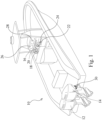
- a marine vessel 10 which is provided with a plurality of propulsion units which, in this example, are in the form of two outboard engines, namely, a port engine 12 and a starboard engine 14.
- the propulsion units may be any number or form of propulsion units.
- the marine vessel 10 is also provided with a control station 16 that supports a steering wheel 18 mounted on a helm 20, a control head 22, and a joystick 24.
- the control station 16 is conventional and allows the port engine 12 and the starboard engine 14 to be steered using either the steering wheel 18 and the helm 20 or the joystick 24 as disclosed in PCT International Application Publication Number WO 2013/1123208 Al which is incorporated herein by reference.
- the control station 16 further includes a first display interface 26 and a second display interface 28.
- the first display interface is a SIMRAD ® display interface which displays navigational information
- the second display interface is a BEP ® display which displays onboard system information.
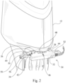
- the port engine 12 of the marine vessel 10 is shown in greater detail in Figure 2 .
- the port engine 12 is provided with an electric actuator 30.
- the electric actuator 30 generally comprises a housing 32 with an output shaft 34 reciprocatingly received therein and spaced-apart housing arms 36 and 38 which extend radially outward of the housing 32.
- a pivot plate 40 can be coupled to each of the housing arms 36 and 38 by respective pivot pins 42 and 44.
- the pivot plate 40 extends between the housing arms 36 and 38.
- the pivot plate 40 can pivot about the pivot pins 42 and 44.
- a steering member or tiller 46 of the port engine 12 can be pivotably coupled to the pivot plate 40 by a tiller pin 48.
- support arms 50 and 52 which connect respective ends of the output shaft 34 of the electric actuator 30 to a support rod 54 and a tilt tube 56 of the port engine 12.
- the support arms 50 and 52 inhibit axial and rotational movement of the output shaft 34 of the electric actuator 30 relative to the marine vessel 10 while the housing 32 of the electric actuator 30 reciprocates along the output shaft 34 and linearly relative to the marine vessel 10. This relative linear movement of the housing 32 causes the tiller 46 of the port engine 12 to pivot and thereby cause the port engine to be steered in a conventional manner.
- the starboard engine 14 has a substantially identical structure and functions in a substantially similar manner. The starboard engine is accordingly not described in detail herein.
- the electric actuator 30 is shown in greater detail in Figure 3 .
- the housing 32 of the electric actuator 30 has a T-shaped profile with longitudinally extending arm portions 58 and 60.
- the longitudinally extending arm portions 58 and 60 of the housing 32 extend longitudinally overlapping the support arms 50 and 52 when the electric actuator 30 strokes to hard over positions, as shown in Figure 4 , for the longitudinally extending arm portion 60 and the support arm 52.
- Wiring 62 is connected to the housing 32 of the electric actuator 30 at the longitudinally extending arm portion 60 along a longitudinal axis 110 which is generally parallel to a longitudinal axis 120 of the output shaft 34 of the electric actuator 30. This may offer advantages in clearance.
- Figure 5 shows a partly broken away view of the electric actuator 30.
- a motor 64 of the electric actuator 30 is disposed such that an output shaft 66 of the motor 64 has a longitudinal axis 130 which is generally parallel to the longitudinal axis 120 of the output shaft 34 of the electric actuator 30.
- the longitudinal axis 120 of the output shaft 34 of the electric actuator 30 and the longitudinal axis 130 of the output shaft 66 of the motor 64 are orthogonal to a longitudinal axis of the marine vessel 10.
- the output shaft 66 of the motor 64 is coupled to a rotor 68 of the electric actuator 30 by a drive mechanism that includes a belt 70, as best shown in Figure 6 , in order to transmit rotational motion from the output shaft 66 of the motor 64 to a rotor 68 of the electric actuator 30.
- the belt 70 is provided with a tensioner 72.
- Use of the belt 70 to couple the output shaft 66 of the motor 64 to the rotor 68 of the electric actuator 30 may dampen out the load impulses from the port engine 12.
- the drive mechanism may employ other means such as an idler gear 74, shown in Figure 7 , to couple the output shaft 66 of the motor 64 to the rotor 68 of the electric actuator 30.
- the drive mechanism is on a plane radial to the longitudinal axis 120 of the output shaft 34 of the electric actuator 30.
- the electric actuator 30 also includes a position sensor 76 for sensing a position of the rotor 68 of the electric actuator 30.
- An actual steering position is determined based on the position of the rotor 68.
- the position sensor may be a rotary positions sensor, or a linear position sensor with a helical magnetic element, or any other suitable sensor.
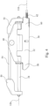
- the position sensor 76 employs a gear reduction which, in this example, is a worm-like drive best shown in Figure 8 .
- There is an outer threading 78 on the rotor 68 which engages a driven sensor gear 80.
- a position of the magnet is sensed by a non-contact position sensor element 86.
- a controller 88 disposed within the housing 32 of the electric actuator, reads the sensor element 86 as the actual steering position. The controller also reads a steering command from the steering wheel 18 and then drives the motor 64 based on a difference between the steering command and the actual steering position.
- the rotor 68 also has inner threading 90 which is shown in Figure 9 .
- the inner threading 90 of the rotor 68 engages a roller screw assembly 92.
- the roller screw assembly is axially and rotationally inhibited by the support arms 50 and 52. It is possible to remove a nut at the support arms, for example nut 94 shown in Figure 8 , to manually reposition the housing.
- the lead of a roller screw assembly 92 of the electric actuator 30 is 0.1 inches, so for an 8.0 inch stroke, the rotor 68 of the electric actuator 30 turns approximately eighty times.
- a reduction gear of >80:1 is accordingly employed so the driven sensor gear 80 never rotates more than one rotation. Disposing the position sensor 76 on the rotor 68 places the position sensor 76 closer to the output of the electric actuator 30 to avoid fault.
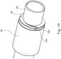
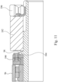
- the electric actuator 30 also includes a clutch 96, which may function as a brake, which is coaxial to the rotor 68 and shown in Figures 10 and 11 .
- the clutch 96 is generally similar to the clutch disclosed in International Patent Application Publication No. WO/2017/004532 in the name of Davidson et al. However, in this example, there is a flexure 98 directly coupled to the rotor 68 without a hub. The flexure 98 pulls back a brake pad 100 when the clutch 96 is released and the flexure 98 transmits torque from the rotor 68 when the clutch 96 is engaged.
- There is a bearing 102 which clamps the flexure 98 against a flange 104 on the rotor 68 of the electric actuator 30.
- There is also a lock nut 106 which allows the clutch 96 to be manually released.
- the electric actuator 30 has an envelope such that the motor 64 of the electric actuator 30 is disposed, relative to the marine vessel 10, in front of the output shaft 34 of the electric actuator 30 in the tilted down position and the tilted up position, and all tilt positions therebetween, as shown in Figures 12 and 13 .
- the motor 64 of the electric actuator 30 is also disposed under the port engine 12 and above a splashwell 108 of the marine vessel in the tilted down position and the tilted up position, and all tilt positions therebetween, as shown in Figures 12 and 13 .
- the housing of the electric actuator is pivotable when the propulsion unit is pivotable.
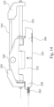
- the actuator 230 is shown in Figures 14 and 15 .
- the actuator 230 is generally similar to the actuator 30, as shown in Figures 4 and 5 , with the following notable exceptions.
- the actuator 230 shown in Figures 14 and 15 is a mirror image of the actuator 30, shown in Figures 4 and 5 , with like parts given like reference numerals in the 200 series.
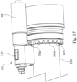
- the actuator 230 is provided with a brake 300 which is shown in Figures 16 and 17 .
- the brake 300 includes a brake pad 302 secured to the rotor 268.
- the brake pad 302 is generally annular and is circumambient to the rotor 268.
- the brake pad 302 has a plurality of radial openings, for example, radial openings 304a and 304b.
- the brake 300 is in an engaged position when a pin 306 engages one of said radial openings, for example, said radial opening 304a as shown in Figure 16 .
- the brake 300 is provided with a solenoid 308 which, when de-energized and as shown in Figure 16 , allows the brake to be in the engaged position with a pin 306 engaging one of said radial openings 304a.
- a biased slider 310 is coupled to the pin 306 and biases the pin 306 to engage one of said radial openings 304a.
- the solenoid 308 is energized, the slider 310 is pushed away from the brake pad 302 and the pin 306 disengages from the brake pad 302, as shown in Figure 17 , when the brake is in the released position.
- the brake 300 is in the engaged position. This prevents the electric actuator 230 from being back driven.
- the brake 300 is released to allow steering.
- the slider 310 allows for manual override by a user.
Landscapes
- Engineering & Computer Science (AREA)
- Mechanical Engineering (AREA)
- General Engineering & Computer Science (AREA)
- Chemical & Material Sciences (AREA)
- Combustion & Propulsion (AREA)
- Ocean & Marine Engineering (AREA)
- Connection Of Motors, Electrical Generators, Mechanical Devices, And The Like (AREA)
Claims (15)
- Elektrischer Stellantrieb (30, 230) für ein Bootsteuerungssystem, wobei der elektrische Stellantrieb Folgendes umfasst:ein Gehäuse (32, 232);eine Ausgangswelle (34, 234) des elektrischen Stellantriebs, die hin- und herbeweglich durch das Gehäuse aufgenommen wird;einen Rotor (68, 268), der innerhalb des Gehäuses angeordnet und an die Ausgangswelle des elektrischen Stellantriebs gekoppelt ist, wobei eine Drehung des Rotors eine Hin- und Herbewegung der Ausgangswelle des elektrischen Stellantriebs bezogen auf das Gehäuse bewirkt;einen Motor (64, 264), der innerhalb des Gehäuses angeordnet ist; undeinen Antriebsmechanismus (70, 74, 270), der innerhalb des Gehäuses angeordnet ist;wobei der Motor eine Ausgangswelle (66, 266) aufweist, die an den Rotor gekoppelt ist, wobei eine Längsachse (130) der Ausgangswelle des Motors parallel zu einer Längsachse (120) der Ausgangswelle des elektrischen Stellantriebs ist; undwobei der Antriebsmechanismus die Ausgangswelle des elektrischen Stellantriebs an den Rotor koppelt, wobei sich der Antriebsmechanismus auf einer Ebene befindet, die radial zu der Längsachse der Ausgangswelle des Motors ist, undwobei ein Außengewinde (78) an dem Rotor in ein angetriebenes Sensorzahnrad (80) eines an dem Rotor angeordneten Positionssensors (76, 276) eingreift, um eine Position des Rotors zu erfassen, undwobei der elektrische Stellantrieb dadurch gekennzeichnet ist, dass Enden der Ausgangswelle (34, 234) mit jeweiligen Stützarmen (50, 52, 250, 252) verbindbar sind, um die Enden der Ausgangswelle mit einer Stützstange (54, 254) und einem Kipprohr (56) einer Antriebseinheit (12, 14) zu verbinden.
- Elektrischer Stellantrieb (30, 230) nach Anspruch 1, wobei ein Magnet (82) an dem Ende einer Welle (84) angeordnet ist, die sich axial von dem angetriebenen Sensorzahnrad (80) erstreckt, und wobei der elektrischer Stellantrieb ein berührungsloses Positionssensorelement (86), das dazu konfiguriert ist, eine Position des Magneten zu erfassen, und eine Steuervorrichtung (88) umfasst, die in dem Gehäuse (32) des elektrischen Stellantriebs angeordnet und dazu konfiguriert ist, das Sensorelement (86) als die tatsächliche Steuerungsposition zu lesen.
- Elektrischer Stellantrieb (30, 230) nach Anspruch 1, wobei der Antriebsmechanismus einen Riemen (70, 270) beinhaltet, der die Ausgangswelle (34, 234) des elektrischen Stellantriebs an den Rotor (68, 268) koppelt.
- Elektrischer Stellantrieb (30, 230) nach Anspruch 1, wobei der Antriebsmechanismus ein Zwischenzahnrad (74) beinhaltet, das die Ausgangswelle (34, 234) des elektrischen Stellantriebs an den Rotor (68, 268) koppelt.
- Elektrischer Stellantrieb (30, 230) nach Anspruch 1, wobei die Verkabelung (62) entlang einer Längsachse (110), die im Allgemeinen parallel zu der Längsachse (120) der Ausgangswelle (34, 234) des elektrischen Stellantriebs ist, mit dem elektrischen Stellantrieb verbunden ist.
- Elektrischer Stellantrieb (30, 230) nach einem der vorhergehenden Ansprüche, wobei der Rotor (68, 268) ein Innengewinde (90) aufweist.
- Elektrischer Stellantrieb (30, 230) nach Anspruch 6, wobei das Innengewinde (90) des Rotors (68) in eine Rollengewindeanordnung (92) eingreift.
- Elektrischer Stellantrieb (30, 230) nach Anspruch 1, wobei der Positionssensor (76, 276) eine tatsächliche Steuerungsposition auf Grundlage einer Position des Rotors (68, 268) erfasst.
- Elektrischer Stellantrieb (30, 230) nach Anspruch 1, wobei der Positionssensor (76, 276) ein Drehpositionssensor ist und der Drehpositionssensor (76, 276) eine Untersetzung einsetzt, sodass sich beispielsweise das angetriebene Sensorzahnrad (80) nie um mehr als eine Umdrehung dreht.
- Elektrischer Stellantrieb (30, 230) nach Anspruch 1, wobei der elektrische Stellantrieb ferner eine Kupplung (96) beinhaltet, die direkt an den Rotor (68, 268) gekoppelt ist.
- Elektrischer Stellantrieb (30, 230) nach Anspruch 10, wobei die Kupplung (96) als Bremse fungiert.
- Steuerungssystem für ein Wasserfahrzeug (10), wobei das Steuerungssystem Folgendes umfasst:den elektrischen Stellantrieb (30, 230) nach Anspruch 1 zum Übertragen einer Steuerungsbewegung auf die Antriebseinheit;eine Antriebseinheit (12, 14), die das Kipprohr (56), die Stützstange (54, 254), die durch das Kipprohr aufgenommen ist, und eine Pinne (46) beinhaltet; undeine Schwenkplatte (40, 240), die schwenkbar mit der Pinne der Antriebseinheit verbunden ist, wobei die Schwenkplatte das Gehäuse des elektrischen Stellantriebs in der Drehung einschränkt, um ein Reaktionsdrehmoment für eine Drehung des Rotors bereitzustellen; unddie Stützarme (50, 52, 250, 252), welche die jeweiligen Enden der Ausgangswelle mit der Stützstange der Antriebseinheit verbinden, wobei die Stützarme eine Drehbeschränkung für die Ausgangswelle bereitstellen und die Stützarme eine axiale Bewegung der Ausgangswelle bezogen auf das Wasserfahrzeug verhindern, während sich das Gehäuse des elektrischen Stellantriebs linear entlang der Ausgangswelle hin- und herbewegt,wobei der Motor des elektrischen Stellantriebs bezogen auf das Wasserfahrzeug vor der Ausgangswelle des elektrischen Stellantriebs in einer nach unten geneigten Position und einer nach oben geneigten Position angeordnet ist.
- Steuerungssystem nach Anspruch 12, wobei der elektrische Stellantrieb (30, 230) in der nach unten gekippten Position und der nach oben gekippten Position unter einer Motorwanne der Antriebseinheit (12, 14) und über einem Spritzwasserschacht (108) des Wasserfahrzeugs (10) angeordnet ist.
- Steuerungssystem nach Anspruch 12, wobei das Gehäuse (32, 232) des elektrischen Stellantriebs (30, 230) schwenkbar ist, wenn die Antriebseinheit (12, 14) schwenkbar ist.
- Steuerungssystem nach Anspruch 12, wobei das Gehäuse (32, 232) ein T-förmiges Profil mit sich längs erstreckenden Armabschnitten (58, 60, 258, 260) aufweist, wobei einer der sich längs erstreckenden Armabschnitte einen jeweiligen der Stützarme (50, 52, 250, 252) überlappt, wenn der elektrische Stellantrieb (30, 230) in eine harte Überschlagsposition ausschlägt.
Applications Claiming Priority (2)
| Application Number | Priority Date | Filing Date | Title |
|---|---|---|---|
| US201762550510P | 2017-08-25 | 2017-08-25 | |
| PCT/CA2018/051029 WO2019036818A1 (en) | 2017-08-25 | 2018-08-27 | ELECTRIC ACTUATOR FOR MARINE GOVERNOR SYSTEM |
Publications (3)
| Publication Number | Publication Date |
|---|---|
| EP3672868A1 EP3672868A1 (de) | 2020-07-01 |
| EP3672868A4 EP3672868A4 (de) | 2020-08-26 |
| EP3672868B1 true EP3672868B1 (de) | 2025-04-30 |
Family
ID=65436975
Family Applications (1)
| Application Number | Title | Priority Date | Filing Date |
|---|---|---|---|
| EP18848466.1A Active EP3672868B1 (de) | 2017-08-25 | 2018-08-27 | Elektrischer stellantrieb für ein bootsteuerungssystem |
Country Status (3)
| Country | Link |
|---|---|
| US (2) | US10683073B2 (de) |
| EP (1) | EP3672868B1 (de) |
| WO (1) | WO2019036818A1 (de) |
Families Citing this family (7)
| Publication number | Priority date | Publication date | Assignee | Title |
|---|---|---|---|---|
| US10683073B2 (en) | 2017-08-25 | 2020-06-16 | Marine Canada Acquisition Inc. | Electric actuator for a marine steering system |
| DE102017221763A1 (de) * | 2017-12-04 | 2019-06-06 | Robert Bosch Gmbh | Sensorsystem zur Bestimmung mindestens einer Rotationseigenschaft eines um mindestens eine Rotationsachse rotierenden Elements |
| US11273894B2 (en) | 2019-02-13 | 2022-03-15 | Marine Canada Acquisition Inc. | Fixed mount electric actuator for marine steering system, and propulsion unit comprising the same |
| US12326735B2 (en) | 2021-07-23 | 2025-06-10 | Seakeeper, Inc. | Dynamic active control system with engine control |
| US12214850B2 (en) | 2021-08-19 | 2025-02-04 | Seakeeper, Inc. | Commissioning strategy |
| US12485998B2 (en) | 2021-08-23 | 2025-12-02 | Seakeeper, Inc. | Mounting plate assembly and system |
| AU2023312810A1 (en) | 2022-07-29 | 2025-02-13 | Seakeeper, Inc. | Distribution module |
Citations (1)
| Publication number | Priority date | Publication date | Assignee | Title |
|---|---|---|---|---|
| US20070105463A1 (en) * | 2005-11-04 | 2007-05-10 | Makoto Mizutani | Electric type steering device for outboard motors |
Family Cites Families (40)
| Publication number | Priority date | Publication date | Assignee | Title |
|---|---|---|---|---|
| FR951949A (fr) * | 1947-08-09 | 1949-11-07 | Auxiliaire Ind L | Vérin à vis, à moteur réversible, et sortie de secours de la tige |
| JPS628459U (de) * | 1985-07-02 | 1987-01-19 | ||
| US4974464A (en) | 1988-03-17 | 1990-12-04 | Erikson Kenneth W | Motorized anti-backlash linear actuator |
| US5214363A (en) * | 1990-10-22 | 1993-05-25 | Syncro Corp. | Remote electrical steering system with fault protection |
| WO1993005321A1 (fr) | 1991-09-04 | 1993-03-18 | Smc Kabushiki Kaisha | Actuateur |
| US5491372A (en) | 1991-10-11 | 1996-02-13 | Exlar Corporation | Electric linear actuator with planetary action |
| US5557154A (en) | 1991-10-11 | 1996-09-17 | Exlar Corporation | Linear actuator with feedback position sensor device |
| DK4094A (da) | 1994-01-10 | 1995-07-11 | Linak As | Lineær aktuator |
| US5461935A (en) | 1994-01-18 | 1995-10-31 | Emerson Electric Co. | Slip clutch linear actuator |
| JP3681201B2 (ja) | 1995-10-31 | 2005-08-10 | 富士通株式会社 | ディスク装置及びディスク装置の組立方法 |
| US5673593A (en) | 1995-12-14 | 1997-10-07 | Joerns Healthcare, Inc. | Overrunning nut for linear actuator |
| US5831360A (en) | 1995-12-15 | 1998-11-03 | Iai Corporation | Actuator |
| JP3122052B2 (ja) * | 1996-12-06 | 2001-01-09 | 株式会社椿本チエイン | ボールねじ軸抜け止め式直線作動機 |
| US5720531A (en) | 1996-12-09 | 1998-02-24 | General Motors Corporation | Variable pitch screw driver for use in a brake system |
| DK151096A (da) | 1996-12-23 | 1998-07-17 | Linak As | Lineær aktuator |
| US6024422A (en) | 1997-05-16 | 2000-02-15 | General Motors Corporation | Large displacement variable pitch screw-driven system |
| US5975234A (en) | 1997-12-03 | 1999-11-02 | Trw Inc. | Electric steering system with plastic motor tube |
| US6113444A (en) | 1999-06-04 | 2000-09-05 | Brunswick Corporation | Steering mechanism for an outboard motor |
| US6892662B2 (en) | 2003-03-03 | 2005-05-17 | Kayaba Industry Co., Ltd. | Power steering device for boat with outboard motor |
| JP2004323414A (ja) | 2003-04-24 | 2004-11-18 | Japan Science & Technology Agency | 14員環マクロライド化合物を利用した、血管平滑筋の増殖に起因する疾患治療剤 |
| JP4327617B2 (ja) | 2004-01-29 | 2009-09-09 | ヤマハ発動機株式会社 | 船舶推進装置のステアリング制御方法 |
| JP4331628B2 (ja) * | 2004-01-29 | 2009-09-16 | ヤマハ発動機株式会社 | 船舶推進装置の操舵装置および船舶 |
| JP4986841B2 (ja) | 2004-02-24 | 2012-07-25 | リナック エー/エス | リニアアクチュエータ |
| JP4327637B2 (ja) * | 2004-03-26 | 2009-09-09 | ヤマハ発動機株式会社 | 船外機の操舵装置および船外機 |
| US20060266146A1 (en) | 2005-05-31 | 2006-11-30 | Waide William M | Direct drive electromechanical linear actuators |
| US7880345B2 (en) | 2006-04-11 | 2011-02-01 | Exlar Corporation | Linear actuator system and method |
| JP4994005B2 (ja) * | 2006-11-17 | 2012-08-08 | ヤマハ発動機株式会社 | 船舶用操舵装置及び船舶 |
| JP5524078B2 (ja) | 2008-01-12 | 2014-06-18 | リナック エー/エス | リニアアクチュエータ |
| TWI426685B (zh) * | 2008-04-17 | 2014-02-11 | Smc Kk | 電動致動器 |
| JP5340640B2 (ja) | 2008-05-26 | 2013-11-13 | Thk株式会社 | 電動リニアアクチュエータ |
| DE102009027418A1 (de) | 2009-07-02 | 2011-01-05 | Zf Friedrichshafen Ag | Elektromechanische Linearstelleinheit |
| CN102639032B (zh) | 2009-12-04 | 2015-11-25 | 利纳克有限公司 | 线性致动器 |
| CN103068673B (zh) * | 2010-08-13 | 2016-09-07 | 日发美克株式会社 | 船外机的操舵装置 |
| JP5656073B2 (ja) * | 2011-02-16 | 2015-01-21 | 株式会社ジェイテクト | 車両用操舵装置および車両用操舵装置の製造方法 |
| WO2013123208A1 (en) | 2012-02-14 | 2013-08-22 | Marine Canada Acquisition, Inc. | A steering system for a marine vessel |
| WO2013156028A1 (en) | 2012-04-16 | 2013-10-24 | Linak A/S | Linear actuator |
| US9381802B2 (en) * | 2013-10-23 | 2016-07-05 | GM Global Technology Operations LLC | Propulsion wheel motor for an electric vehicle |
| AU2015286161B2 (en) * | 2014-07-08 | 2019-09-12 | Marine Canada Acquisition Inc. | Electric actuator for a marine steering system |
| JP2016210239A (ja) * | 2015-04-30 | 2016-12-15 | ヤマハ発動機株式会社 | 船舶用ステアリングシステム |
| US10683073B2 (en) | 2017-08-25 | 2020-06-16 | Marine Canada Acquisition Inc. | Electric actuator for a marine steering system |
-
2018
- 2018-08-27 US US16/114,137 patent/US10683073B2/en active Active
- 2018-08-27 EP EP18848466.1A patent/EP3672868B1/de active Active
- 2018-08-27 WO PCT/CA2018/051029 patent/WO2019036818A1/en not_active Ceased
-
2020
- 2020-05-22 US US16/881,676 patent/US10981638B2/en active Active
Patent Citations (1)
| Publication number | Priority date | Publication date | Assignee | Title |
|---|---|---|---|---|
| US20070105463A1 (en) * | 2005-11-04 | 2007-05-10 | Makoto Mizutani | Electric type steering device for outboard motors |
Also Published As
| Publication number | Publication date |
|---|---|
| WO2019036818A1 (en) | 2019-02-28 |
| US10981638B2 (en) | 2021-04-20 |
| EP3672868A1 (de) | 2020-07-01 |
| US20190061898A1 (en) | 2019-02-28 |
| EP3672868A4 (de) | 2020-08-26 |
| US10683073B2 (en) | 2020-06-16 |
| US20200283112A1 (en) | 2020-09-10 |
Similar Documents
| Publication | Publication Date | Title |
|---|---|---|
| US10981638B2 (en) | Electric actuator for a marine steering system | |
| US11433981B2 (en) | Electric actuator for a marine steering system, and methods of defining steering boundaries and determining drive mechanism failure thereof | |
| US8007330B2 (en) | Steering apparatus with integrated steering actuator | |
| US20210061429A1 (en) | Watercraft and associated pedal drive system | |
| US11572143B2 (en) | Watercraft and associated pedal drive system | |
| CN103068673A (zh) | 船外机的操舵装置 | |
| KR100429068B1 (ko) | 선박용 자동조타 및 자동제어 장치 | |
| JP2019199104A (ja) | 船外機 | |
| US7435146B2 (en) | Forward and reverse drive switching device for outboard motor | |
| US12539952B2 (en) | Marine drives having hydraulically actuated steerable gearcase | |
| US11230360B2 (en) | Electric power steering system for marine vessel | |
| US12600450B2 (en) | Stern drives having steerable gearcase | |
| US20240326972A1 (en) | Electric actuator for a marine steering system | |
| CA2455608C (en) | Outboard motor | |
| US20240092471A1 (en) | Electric stern drives | |
| JP4283646B2 (ja) | 船外機用シフト操作装置 | |
| EP4707160A1 (de) | Schiffsantriebsvorrichtung | |
| US20230303230A1 (en) | Stern drives and methods of installing stern drives | |
| EP4357642B1 (de) | Elektrischer kabelantriebsmechanismus mit selbstrückstellfunktion | |
| EP4261122A1 (de) | Schiffsantriebe mit lenkbarem getriebegehäuse | |
| EP2492186B1 (de) | Leistungsübertragungsvorrichtung für Außenbordmotor | |
| CA3135262C (en) | Watercraft and associated pedal drive system | |
| JP2006306174A (ja) | 船舶推進機の電動パワーステアリング装置 | |
| US10118683B1 (en) | Outboard motors having flexible connector assembly for shift actuation | |
| JP3318902B2 (ja) | 船外機の操舵ハンドル |
Legal Events
| Date | Code | Title | Description |
|---|---|---|---|
| STAA | Information on the status of an ep patent application or granted ep patent |
Free format text: STATUS: THE INTERNATIONAL PUBLICATION HAS BEEN MADE |
|
| PUAI | Public reference made under article 153(3) epc to a published international application that has entered the european phase |
Free format text: ORIGINAL CODE: 0009012 |
|
| STAA | Information on the status of an ep patent application or granted ep patent |
Free format text: STATUS: REQUEST FOR EXAMINATION WAS MADE |
|
| 17P | Request for examination filed |
Effective date: 20200325 |
|
| AK | Designated contracting states |
Kind code of ref document: A1 Designated state(s): AL AT BE BG CH CY CZ DE DK EE ES FI FR GB GR HR HU IE IS IT LI LT LU LV MC MK MT NL NO PL PT RO RS SE SI SK SM TR |
|
| AX | Request for extension of the european patent |
Extension state: BA ME |
|
| A4 | Supplementary search report drawn up and despatched |
Effective date: 20200723 |
|
| RIC1 | Information provided on ipc code assigned before grant |
Ipc: F16H 19/06 20060101ALI20200718BHEP Ipc: B63H 20/12 20060101AFI20200718BHEP Ipc: B63H 25/52 20060101ALI20200718BHEP |
|
| DAV | Request for validation of the european patent (deleted) | ||
| DAX | Request for extension of the european patent (deleted) | ||
| STAA | Information on the status of an ep patent application or granted ep patent |
Free format text: STATUS: EXAMINATION IS IN PROGRESS |
|
| 17Q | First examination report despatched |
Effective date: 20220720 |
|
| RAP3 | Party data changed (applicant data changed or rights of an application transferred) |
Owner name: DOMETIC MARINE CANADA INC. |
|
| P01 | Opt-out of the competence of the unified patent court (upc) registered |
Effective date: 20230526 |
|
| GRAP | Despatch of communication of intention to grant a patent |
Free format text: ORIGINAL CODE: EPIDOSNIGR1 |
|
| STAA | Information on the status of an ep patent application or granted ep patent |
Free format text: STATUS: GRANT OF PATENT IS INTENDED |
|
| INTG | Intention to grant announced |
Effective date: 20241128 |
|
| GRAJ | Information related to disapproval of communication of intention to grant by the applicant or resumption of examination proceedings by the epo deleted |
Free format text: ORIGINAL CODE: EPIDOSDIGR1 |
|
| STAA | Information on the status of an ep patent application or granted ep patent |
Free format text: STATUS: EXAMINATION IS IN PROGRESS |
|
| GRAP | Despatch of communication of intention to grant a patent |
Free format text: ORIGINAL CODE: EPIDOSNIGR1 |
|
| STAA | Information on the status of an ep patent application or granted ep patent |
Free format text: STATUS: GRANT OF PATENT IS INTENDED |
|
| INTC | Intention to grant announced (deleted) | ||
| GRAS | Grant fee paid |
Free format text: ORIGINAL CODE: EPIDOSNIGR3 |
|
| INTG | Intention to grant announced |
Effective date: 20250224 |
|
| GRAA | (expected) grant |
Free format text: ORIGINAL CODE: 0009210 |
|
| STAA | Information on the status of an ep patent application or granted ep patent |
Free format text: STATUS: THE PATENT HAS BEEN GRANTED |
|
| AK | Designated contracting states |
Kind code of ref document: B1 Designated state(s): AL AT BE BG CH CY CZ DE DK EE ES FI FR GB GR HR HU IE IS IT LI LT LU LV MC MK MT NL NO PL PT RO RS SE SI SK SM TR |
|
| REG | Reference to a national code |
Ref country code: CH Ref legal event code: EP Ref country code: GB Ref legal event code: FG4D |
|
| REG | Reference to a national code |
Ref country code: IE Ref legal event code: FG4D |
|
| REG | Reference to a national code |
Ref country code: DE Ref legal event code: R096 Ref document number: 602018081591 Country of ref document: DE |
|
| REG | Reference to a national code |
Ref country code: NL Ref legal event code: MP Effective date: 20250430 |
|
| REG | Reference to a national code |
Ref country code: AT Ref legal event code: MK05 Ref document number: 1789835 Country of ref document: AT Kind code of ref document: T Effective date: 20250430 |
|
| PG25 | Lapsed in a contracting state [announced via postgrant information from national office to epo] |
Ref country code: FI Free format text: LAPSE BECAUSE OF FAILURE TO SUBMIT A TRANSLATION OF THE DESCRIPTION OR TO PAY THE FEE WITHIN THE PRESCRIBED TIME-LIMIT Effective date: 20250430 Ref country code: ES Free format text: LAPSE BECAUSE OF FAILURE TO SUBMIT A TRANSLATION OF THE DESCRIPTION OR TO PAY THE FEE WITHIN THE PRESCRIBED TIME-LIMIT Effective date: 20250430 Ref country code: PT Free format text: LAPSE BECAUSE OF FAILURE TO SUBMIT A TRANSLATION OF THE DESCRIPTION OR TO PAY THE FEE WITHIN THE PRESCRIBED TIME-LIMIT Effective date: 20250901 |
|
| REG | Reference to a national code |
Ref country code: LT Ref legal event code: MG9D |
|
| PG25 | Lapsed in a contracting state [announced via postgrant information from national office to epo] |
Ref country code: NO Free format text: LAPSE BECAUSE OF FAILURE TO SUBMIT A TRANSLATION OF THE DESCRIPTION OR TO PAY THE FEE WITHIN THE PRESCRIBED TIME-LIMIT Effective date: 20250730 Ref country code: GR Free format text: LAPSE BECAUSE OF FAILURE TO SUBMIT A TRANSLATION OF THE DESCRIPTION OR TO PAY THE FEE WITHIN THE PRESCRIBED TIME-LIMIT Effective date: 20250731 |
|
| PG25 | Lapsed in a contracting state [announced via postgrant information from national office to epo] |
Ref country code: NL Free format text: LAPSE BECAUSE OF FAILURE TO SUBMIT A TRANSLATION OF THE DESCRIPTION OR TO PAY THE FEE WITHIN THE PRESCRIBED TIME-LIMIT Effective date: 20250430 Ref country code: PL Free format text: LAPSE BECAUSE OF FAILURE TO SUBMIT A TRANSLATION OF THE DESCRIPTION OR TO PAY THE FEE WITHIN THE PRESCRIBED TIME-LIMIT Effective date: 20250430 |
|
| PG25 | Lapsed in a contracting state [announced via postgrant information from national office to epo] |
Ref country code: BG Free format text: LAPSE BECAUSE OF FAILURE TO SUBMIT A TRANSLATION OF THE DESCRIPTION OR TO PAY THE FEE WITHIN THE PRESCRIBED TIME-LIMIT Effective date: 20250430 |
|
| PG25 | Lapsed in a contracting state [announced via postgrant information from national office to epo] |
Ref country code: HR Free format text: LAPSE BECAUSE OF FAILURE TO SUBMIT A TRANSLATION OF THE DESCRIPTION OR TO PAY THE FEE WITHIN THE PRESCRIBED TIME-LIMIT Effective date: 20250430 |
|
| PG25 | Lapsed in a contracting state [announced via postgrant information from national office to epo] |
Ref country code: AT Free format text: LAPSE BECAUSE OF FAILURE TO SUBMIT A TRANSLATION OF THE DESCRIPTION OR TO PAY THE FEE WITHIN THE PRESCRIBED TIME-LIMIT Effective date: 20250430 |
|
| PG25 | Lapsed in a contracting state [announced via postgrant information from national office to epo] |
Ref country code: RS Free format text: LAPSE BECAUSE OF FAILURE TO SUBMIT A TRANSLATION OF THE DESCRIPTION OR TO PAY THE FEE WITHIN THE PRESCRIBED TIME-LIMIT Effective date: 20250731 |
|
| PG25 | Lapsed in a contracting state [announced via postgrant information from national office to epo] |
Ref country code: IS Free format text: LAPSE BECAUSE OF FAILURE TO SUBMIT A TRANSLATION OF THE DESCRIPTION OR TO PAY THE FEE WITHIN THE PRESCRIBED TIME-LIMIT Effective date: 20250830 |
|
| PG25 | Lapsed in a contracting state [announced via postgrant information from national office to epo] |
Ref country code: LV Free format text: LAPSE BECAUSE OF FAILURE TO SUBMIT A TRANSLATION OF THE DESCRIPTION OR TO PAY THE FEE WITHIN THE PRESCRIBED TIME-LIMIT Effective date: 20250430 |
|
| PG25 | Lapsed in a contracting state [announced via postgrant information from national office to epo] |
Ref country code: DK Free format text: LAPSE BECAUSE OF FAILURE TO SUBMIT A TRANSLATION OF THE DESCRIPTION OR TO PAY THE FEE WITHIN THE PRESCRIBED TIME-LIMIT Effective date: 20250430 Ref country code: SM Free format text: LAPSE BECAUSE OF FAILURE TO SUBMIT A TRANSLATION OF THE DESCRIPTION OR TO PAY THE FEE WITHIN THE PRESCRIBED TIME-LIMIT Effective date: 20250430 |
|
| PG25 | Lapsed in a contracting state [announced via postgrant information from national office to epo] |
Ref country code: CZ Free format text: LAPSE BECAUSE OF FAILURE TO SUBMIT A TRANSLATION OF THE DESCRIPTION OR TO PAY THE FEE WITHIN THE PRESCRIBED TIME-LIMIT Effective date: 20250430 |
|
| PG25 | Lapsed in a contracting state [announced via postgrant information from national office to epo] |
Ref country code: EE Free format text: LAPSE BECAUSE OF FAILURE TO SUBMIT A TRANSLATION OF THE DESCRIPTION OR TO PAY THE FEE WITHIN THE PRESCRIBED TIME-LIMIT Effective date: 20250430 |
|
| PG25 | Lapsed in a contracting state [announced via postgrant information from national office to epo] |
Ref country code: SK Free format text: LAPSE BECAUSE OF FAILURE TO SUBMIT A TRANSLATION OF THE DESCRIPTION OR TO PAY THE FEE WITHIN THE PRESCRIBED TIME-LIMIT Effective date: 20250430 Ref country code: RO Free format text: LAPSE BECAUSE OF FAILURE TO SUBMIT A TRANSLATION OF THE DESCRIPTION OR TO PAY THE FEE WITHIN THE PRESCRIBED TIME-LIMIT Effective date: 20250430 |
|
| REG | Reference to a national code |
Ref country code: DE Ref legal event code: R097 Ref document number: 602018081591 Country of ref document: DE |
|
| REG | Reference to a national code |
Ref country code: DE Ref legal event code: R119 Ref document number: 602018081591 Country of ref document: DE |
|
| PLBE | No opposition filed within time limit |
Free format text: ORIGINAL CODE: 0009261 |
|
| STAA | Information on the status of an ep patent application or granted ep patent |
Free format text: STATUS: NO OPPOSITION FILED WITHIN TIME LIMIT |
|
| REG | Reference to a national code |
Ref country code: CH Ref legal event code: L10 Free format text: ST27 STATUS EVENT CODE: U-0-0-L10-L00 (AS PROVIDED BY THE NATIONAL OFFICE) Effective date: 20260311 |
|
| REG | Reference to a national code |
Ref country code: CH Ref legal event code: H13 Free format text: ST27 STATUS EVENT CODE: U-0-0-H10-H13 (AS PROVIDED BY THE NATIONAL OFFICE) Effective date: 20260324 |
|
| PG25 | Lapsed in a contracting state [announced via postgrant information from national office to epo] |
Ref country code: MC Free format text: LAPSE BECAUSE OF FAILURE TO SUBMIT A TRANSLATION OF THE DESCRIPTION OR TO PAY THE FEE WITHIN THE PRESCRIBED TIME-LIMIT Effective date: 20250430 |
|
| 26N | No opposition filed |
Effective date: 20260202 |
|
| PG25 | Lapsed in a contracting state [announced via postgrant information from national office to epo] |
Ref country code: LU Free format text: LAPSE BECAUSE OF NON-PAYMENT OF DUE FEES Effective date: 20250827 |
|
| PG25 | Lapsed in a contracting state [announced via postgrant information from national office to epo] |
Ref country code: CH Free format text: LAPSE BECAUSE OF NON-PAYMENT OF DUE FEES Effective date: 20250831 |
|
| GBPC | Gb: european patent ceased through non-payment of renewal fee |
Effective date: 20250827 |
|
| REG | Reference to a national code |
Ref country code: BE Ref legal event code: MM Effective date: 20250831 |
|
| PG25 | Lapsed in a contracting state [announced via postgrant information from national office to epo] |
Ref country code: LT Free format text: LAPSE BECAUSE OF FAILURE TO SUBMIT A TRANSLATION OF THE DESCRIPTION OR TO PAY THE FEE WITHIN THE PRESCRIBED TIME-LIMIT Effective date: 20250430 |
|
| PG25 | Lapsed in a contracting state [announced via postgrant information from national office to epo] |
Ref country code: GB Free format text: LAPSE BECAUSE OF NON-PAYMENT OF DUE FEES Effective date: 20250827 |
|
| PGFP | Annual fee paid to national office [announced via postgrant information from national office to epo] |
Ref country code: IT Payment date: 20260619 Year of fee payment: 9 |
|
| PG25 | Lapsed in a contracting state [announced via postgrant information from national office to epo] |
Ref country code: DE Free format text: LAPSE BECAUSE OF NON-PAYMENT OF DUE FEES Effective date: 20260303 |
|
| PG25 | Lapsed in a contracting state [announced via postgrant information from national office to epo] |
Ref country code: BE Free format text: LAPSE BECAUSE OF NON-PAYMENT OF DUE FEES Effective date: 20250831 Ref country code: IE Free format text: LAPSE BECAUSE OF NON-PAYMENT OF DUE FEES Effective date: 20250827 |
|
| PGFP | Annual fee paid to national office [announced via postgrant information from national office to epo] |
Ref country code: FR Payment date: 20260625 Year of fee payment: 9 |
|
| PG25 | Lapsed in a contracting state [announced via postgrant information from national office to epo] |
Ref country code: SE Free format text: LAPSE BECAUSE OF FAILURE TO SUBMIT A TRANSLATION OF THE DESCRIPTION OR TO PAY THE FEE WITHIN THE PRESCRIBED TIME-LIMIT Effective date: 20250430 |