EP3672903B1 - Procédé pour remplir des récipients avec des produits - Google Patents
Procédé pour remplir des récipients avec des produits Download PDFInfo
- Publication number
- EP3672903B1 EP3672903B1 EP18759594.7A EP18759594A EP3672903B1 EP 3672903 B1 EP3672903 B1 EP 3672903B1 EP 18759594 A EP18759594 A EP 18759594A EP 3672903 B1 EP3672903 B1 EP 3672903B1
- Authority
- EP
- European Patent Office
- Prior art keywords
- filling
- valves
- valve
- volume flow
- control
- Prior art date
- Legal status (The legal status is an assumption and is not a legal conclusion. Google has not performed a legal analysis and makes no representation as to the accuracy of the status listed.)
- Active
Links
Images


Classifications
-
- B—PERFORMING OPERATIONS; TRANSPORTING
- B67—OPENING, CLOSING OR CLEANING BOTTLES, JARS OR SIMILAR CONTAINERS; LIQUID HANDLING
- B67C—CLEANING, FILLING WITH LIQUIDS OR SEMILIQUIDS, OR EMPTYING, OF BOTTLES, JARS, CANS, CASKS, BARRELS, OR SIMILAR CONTAINERS, NOT OTHERWISE PROVIDED FOR; FUNNELS
- B67C3/00—Bottling liquids or semiliquids; Filling jars or cans with liquids or semiliquids using bottling or like apparatus; Filling casks or barrels with liquids or semiliquids
- B67C3/02—Bottling liquids or semiliquids; Filling jars or cans with liquids or semiliquids using bottling or like apparatus
- B67C3/22—Details
- B67C3/28—Flow-control devices, e.g. using valves
- B67C3/286—Flow-control devices, e.g. using valves related to flow rate control, i.e. controlling slow and fast filling phases
-
- B—PERFORMING OPERATIONS; TRANSPORTING
- B67—OPENING, CLOSING OR CLEANING BOTTLES, JARS OR SIMILAR CONTAINERS; LIQUID HANDLING
- B67C—CLEANING, FILLING WITH LIQUIDS OR SEMILIQUIDS, OR EMPTYING, OF BOTTLES, JARS, CANS, CASKS, BARRELS, OR SIMILAR CONTAINERS, NOT OTHERWISE PROVIDED FOR; FUNNELS
- B67C3/00—Bottling liquids or semiliquids; Filling jars or cans with liquids or semiliquids using bottling or like apparatus; Filling casks or barrels with liquids or semiliquids
- B67C3/02—Bottling liquids or semiliquids; Filling jars or cans with liquids or semiliquids using bottling or like apparatus
- B67C3/22—Details
- B67C3/26—Filling-heads; Means for engaging filling-heads with bottle necks
-
- B—PERFORMING OPERATIONS; TRANSPORTING
- B67—OPENING, CLOSING OR CLEANING BOTTLES, JARS OR SIMILAR CONTAINERS; LIQUID HANDLING
- B67C—CLEANING, FILLING WITH LIQUIDS OR SEMILIQUIDS, OR EMPTYING, OF BOTTLES, JARS, CANS, CASKS, BARRELS, OR SIMILAR CONTAINERS, NOT OTHERWISE PROVIDED FOR; FUNNELS
- B67C3/00—Bottling liquids or semiliquids; Filling jars or cans with liquids or semiliquids using bottling or like apparatus; Filling casks or barrels with liquids or semiliquids
- B67C3/02—Bottling liquids or semiliquids; Filling jars or cans with liquids or semiliquids using bottling or like apparatus
- B67C3/22—Details
- B67C3/28—Flow-control devices, e.g. using valves
- B67C3/287—Flow-control devices, e.g. using valves related to flow control using predetermined or real-time calculated parameters
-
- B—PERFORMING OPERATIONS; TRANSPORTING
- B67—OPENING, CLOSING OR CLEANING BOTTLES, JARS OR SIMILAR CONTAINERS; LIQUID HANDLING
- B67C—CLEANING, FILLING WITH LIQUIDS OR SEMILIQUIDS, OR EMPTYING, OF BOTTLES, JARS, CANS, CASKS, BARRELS, OR SIMILAR CONTAINERS, NOT OTHERWISE PROVIDED FOR; FUNNELS
- B67C3/00—Bottling liquids or semiliquids; Filling jars or cans with liquids or semiliquids using bottling or like apparatus; Filling casks or barrels with liquids or semiliquids
- B67C3/02—Bottling liquids or semiliquids; Filling jars or cans with liquids or semiliquids using bottling or like apparatus
- B67C3/22—Details
- B67C3/26—Filling-heads; Means for engaging filling-heads with bottle necks
- B67C2003/2685—Details of probes
-
- B—PERFORMING OPERATIONS; TRANSPORTING
- B67—OPENING, CLOSING OR CLEANING BOTTLES, JARS OR SIMILAR CONTAINERS; LIQUID HANDLING
- B67C—CLEANING, FILLING WITH LIQUIDS OR SEMILIQUIDS, OR EMPTYING, OF BOTTLES, JARS, CANS, CASKS, BARRELS, OR SIMILAR CONTAINERS, NOT OTHERWISE PROVIDED FOR; FUNNELS
- B67C3/00—Bottling liquids or semiliquids; Filling jars or cans with liquids or semiliquids using bottling or like apparatus; Filling casks or barrels with liquids or semiliquids
- B67C3/007—Applications of control, warning or safety devices in filling machinery
-
- B—PERFORMING OPERATIONS; TRANSPORTING
- B67—OPENING, CLOSING OR CLEANING BOTTLES, JARS OR SIMILAR CONTAINERS; LIQUID HANDLING
- B67C—CLEANING, FILLING WITH LIQUIDS OR SEMILIQUIDS, OR EMPTYING, OF BOTTLES, JARS, CANS, CASKS, BARRELS, OR SIMILAR CONTAINERS, NOT OTHERWISE PROVIDED FOR; FUNNELS
- B67C3/00—Bottling liquids or semiliquids; Filling jars or cans with liquids or semiliquids using bottling or like apparatus; Filling casks or barrels with liquids or semiliquids
- B67C3/02—Bottling liquids or semiliquids; Filling jars or cans with liquids or semiliquids using bottling or like apparatus
- B67C3/20—Bottling liquids or semiliquids; Filling jars or cans with liquids or semiliquids using bottling or like apparatus with provision for metering the liquids to be introduced, e.g. when adding syrups
-
- F—MECHANICAL ENGINEERING; LIGHTING; HEATING; WEAPONS; BLASTING
- F17—STORING OR DISTRIBUTING GASES OR LIQUIDS
- F17C—VESSELS FOR CONTAINING OR STORING COMPRESSED, LIQUEFIED OR SOLIDIFIED GASES; FIXED-CAPACITY GAS-HOLDERS; FILLING VESSELS WITH, OR DISCHARGING FROM VESSELS, COMPRESSED, LIQUEFIED, OR SOLIDIFIED GASES
- F17C2250/00—Accessories; Control means; Indicating, measuring or monitoring of parameters
- F17C2250/04—Indicating or measuring of parameters as input values
- F17C2250/0404—Parameters indicated or measured
- F17C2250/0426—Volume
Definitions
- the present invention relates to a method for filling containers with a filling product in a filling product filling plant.
- filling product filling systems it is known to fill containers to be filled with a filling product, the actual introduction of the filling product into the respective container to be filled being carried out by means of a so-called filling valve.
- the filling valve provides a connection between the filling product reservoir, in which the filling product to be filled is provided before the actual filling, and the container to be filled.
- the filling process is initiated by means of the filling valve and the product to be filled is guided into the container to be filled and the filling process is terminated again after a specific specification has been reached, for example after a specified filling weight, a specified filling height or a specified filling volume has been reached.
- Various sensors are known for determining the respective end of filling and thus for determining the respective state or time at which the filling valve is closed again, by means of which, for example, the filling level, the filling weight or the filling volume of the filling product in the container to be filled is determined.
- Filling valves are known which merely open and close the respective connection between the filling product reservoir and the container to be filled.
- a throttle device is often connected upstream of these simply switching filling valves, by means of which a modulation of the filling product flow into the container to be filled can be achieved.
- filling valves which are also referred to as proportional valves, in which the respective filling valve cone is stepped or stepless relative to its filling valve seat can be raised or lowered, as a result of which the gap or annular gap forming between the filling valve cone and the filling valve seat can be varied in its cross section.
- proportional valves in which a variation of the effective cross section and thus also a variation of the filling product flow flowing through the proportional valve can be achieved. It is thus possible with the proportional valve to specify or to control a predetermined volume flow profile for the filling of the respective container to be filled.
- the highest possible volume flow is set in order to achieve rapid filling of the container to be filled.
- the volume flow is then reduced again in order to make it possible to reliably reach the specified end of filling and to prevent the filling product from overflowing or squirting out of the container to be filled.
- Proportional valves are often coupled in a control loop with a flow meter associated with this proportional valve. In this way, it is possible to use the combination of flow meter and proportional valve to specify a volume flow from a higher-level system control, which is then maintained via the control loop.
- both the flow meter and the corresponding evaluation device and the control of the proportional valve entail a certain inertia and time delay, so that an immediate reaction to changes in the initial conditions and in particular to changes in the supply of the filling product to the proportional valve can only be corrected with a certain time delay be able.
- flow meters are often dependent on the properties of the respective filling product.
- each filling valve is connected directly to the filling product reservoir
- the filling product reservoir acts as a buffer, such that each filling valve and in particular each proportional valve is operated independently of the other filling valves or proportional valve.
- they change Initial conditions for the respective filling valve not when an adjacent filling valve is opened or closed, since the filling product reservoir serves as a large-volume buffer.
- the initial conditions for each individual filling valve are influenced due to the properties of the line. This is the case, for example, if the filling product reservoir in which the filling product to be filled is provided is designed as a boiler provided and the filling product is connected to all filling valves of the filler carousel via a single filling product feed line, which is routed to the respective filler carousel via a rotary distributor.
- the pressure provided in the filling product feed line decreases when, at the beginning of the filling operation, starting from a state in which all filling valves are closed, one filling valve after the other is opened.
- the filling product supply line cannot then act as a quasi-unlimited buffer, but rather the volumetric flow flowing through the filling product supply line is dependent on the line radius to the fourth power.
- the filling valves influence each other accordingly--at least until a steady state of equilibrium has been reached. This can mean that even with a filling valve controlled by a flow meter, the actually required flow rate is not achieved at least at the beginning of the respective filling operation due to the inertia of the control loop. This behavior of the filling valves is also observed towards the end of the filling operation, when all filling valves are closed one after the other before production is ended. Here, too, it happens that even with a filling valve controlled by a flow meter, the actually required flow rate is not achieved at the end of the respective filling operation due to the inertia of the control loop.
- the EP 2 695 846 A1 describes a method for calculating the filling quantity in a rotary device and also a method for filling a container with a filling product in a filling product filling system having several filling valves by means of differential pressure determination, volume flow calculation and timed valve control based on the determined differential pressure.
- the WO 97/00224 A1 describes a method for filling containers with a pressurized liquid.
- the EP 1 127 835 A1 describes a system and method for filling containers with a liquid product.
- a method for filling a container with a filling product in a filling product filling system having a control valve is proposed with the following steps: determining a differential pressure ⁇ p v dropping across the control valve and regulating and/or controlling the control valve depending on the determined differential pressure ⁇ p v .
- a function of the volume flow q ( t , ⁇ p v ) for the control valve as a function of the differential pressure ⁇ p v dropping across the control valve is preferably determined, the volume flow q ( t , ⁇ p v ) through the control valve based on the determined differential pressure ⁇ p v is calculated and the control valve is regulated and/or controlled as a function of the calculated volume flow q ( t , ⁇ p v ), t is the time.
- control behavior can also be included and, in particular, the transient behavior of the control valve can be taken into account.
- At least two filling valves connected in parallel are provided in the filling product filling system, and a function of the volume flow q ( t , ⁇ p v ) for at least two of the filling valves connected in parallel is determined as a function of a differential pressure ⁇ p v across the filling valves connected in parallel, the differential pressure ⁇ p v over the parallel connected filling valves is determined, the volume flow q ( t , ⁇ p v ) through at least one of the filling valves connected in parallel is calculated on the basis of the determined differential pressure ⁇ p v and the at least one filling valve is controlled as a function of the calculated volume flow q ( t , ⁇ p v ).
- Regulating and/or controlling the at least one filling valve correspondingly includes compensation for the opening position of the filling valve when the differential pressure ⁇ p v changes using the calculated current volume flow q ( t , ⁇ p v ) .
- a function of the volume flow q ( t, ⁇ p v ) is determined as a function of a differential pressure ⁇ p v across the filling valves connected in parallel and the at least one filling valve is activated as a function of the calculated volume flow q ( t, ⁇ p v ) is controlled, it can be achieved that the control behavior is improved when filling the respective container.
- the control behavior is improved when filling the respective container.
- due to the lower inertia of the differential pressure measurement it is possible to react more quickly to a change in the differential pressure within the device, which is usually due to the fact that further filling valves connected in parallel are switched on or off.
- the filling process begins and the first filling valve is opened first, while all other filling valves are still closed, a higher differential pressure will result, so that initially, in principle, due to this differential pressure, a higher volume flow through the or the few open filling valves is to be expected.
- the corresponding filling valve is regulated or controlled according to the calculated volume flow in comparison to the desired volume flow, so that it is opened to a lesser extent.
- the filling product can flow in with the desired volume flow.
- the differential pressure dropping across the filling valves decreases accordingly, so that the volume flow through the first filling valve and then also through the second filling valve decreases slightly.
- the regulation based on the differential pressure reacts much more quickly than regulation using a flow meter, for example, could.
- a time delay in the regulation of the filling valve is therefore shorter and the result achieved, namely the maintenance of the specified volume flow, is therefore more precise by means of the regulation and/or control based on the calculated volume flow.
- the determined function of the volume flow which depends on the differential pressure across the filling valves connected in parallel, can be used to calculate the volume flow through the filling valve and, with a correspondingly varying differential pressure across the filling valves connected in parallel, the respective opening stroke of the filling valves can be adjusted in order to to maintain the desired or predetermined volume flow in the respective container to be filled, regardless of the number and degree of opening of the other filling valves connected in parallel.
- a volume flow profile predetermined by the filling method for the respective filling product and the respective container to be filled is particularly preferred.
- the filling valves are, for example, controlled via their respective individual flow meters, driven towards the specified volume flow profile. Accordingly, the respective filling valve is set to a predetermined opening value, which is assumed to correspond to the corresponding volume flow predetermined by the volume flow profile, and is then regulated precisely to this value via the respective flow meter.
- the corresponding filling valve can be controlled to the appropriate position, which results from the volume flow profile with compensation by the calculated volume flow based on the determined differential pressure .
- the compensation based on the differential pressure can take place, for example, in a time range of one millisecond due to the fast-reacting pressure sensors.
- regulation by changing the flow rate using the flow meter would require a regulation time of around 50 milliseconds.
- due to the compensation modulated onto the volume flow profile provided a more precise filling behavior can be achieved, so that incorrect filling can be better avoided.
- filling can take place with a correct filling product volume flow.
- each additional filling valve that is opened it decreases the differential pressure across the filling valves connected in parallel to one another, since the total cross-section of the open filling valves increases and the pressure above the filling valves is reduced.
- the volume flow through the individual filling valves is thus also reduced in such a way that the filling valves have to be opened further in order to maintain the filling product volume flow desired according to the volume flow profile.
- the regulation and/or control of the filling valve includes the actuation of an open position of the filling valve based on the current volume flow q ( t , ⁇ pv ) .
- the regulation and/or control of the at least one filling valve is preferably carried out taking into account a predetermined volume flow profile for filling the container to be filled with the filling product.
- the volume flow can also be calculated for a complex system with a large number of filling valves on the basis of the differential pressure, with the mutual influence of the volume flows of the filling valves on one another being taken into account by these equations.
- the calculation in this way enables a more precise calculation of the volume flow and thus an improved filling result.
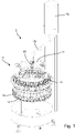
- FIG 1 a schematic perspective view of a filler carousel 10 is shown, which has a large number of filling valves 12 arranged around the circumference of the filler carousel 10, each of which has a filling valve outlet 14 under which the containers to be filled, not shown in this figure, are arranged.
- the container to be filled which is arranged underneath, is filled with a filling product via the respective filling valve outlet 14 .
- the filling valve 12 serves to fill the desired volume, the desired mass or the desired level of filling product into each container to be filled.
- the filler carousel 10 rotates about its axis of rotation in order to produce a constant stream of filled containers.
- a dedicated fill product reservoir 16 in the form of a dedicated fill product kettle is provided.
- the filling product is stored in the filling product reservoir 16 before the containers to be filled are actually filled.
- the filling level of the filling product in the filling product reservoir 16 can be kept constant via a separate mechanism, for example by means of a filling level sensor in the filling product reservoir 16, via which a supply of filling product into the filling product reservoir 16 is regulated.
- the advantage of keeping the filling level in the filling product reservoir 16 constant is that the pressure and flow conditions in the system areas downstream of the filling product reservoir 16 can be determined more easily, since the hydrostatic pressure applied via the filling product reservoir 16 is always the same.
- the filling level of the filling product in the filling product reservoir 16 can also be determined via a filling level sensor and the system parts located downstream of the filling product reservoir 16 can be controlled or regulated according to the filling level of the filling product.
- the filling product reservoir 16 is connected to the individual filling valves 12 via a filling product line 18 which is routed to the filler carousel 10 via a rotary distributor 19 .
- all filling valves 12 are connected to the filling product reservoir 16 that is provided via the filling product supply line 18 and the rotary distributor 19 .
- the individual filling valves 12 are connected to one another via a ring line 11 located on the filler carousel 10 and the ring line 11 is connected to the filling product supply line 18 via four distributor lines 17 with the rotary distributor 19 being interposed.
- Other line-based constellations for connecting the filling product supply line 18 to the filling valves 12 can also be provided here.
- This structure of the filler with an adjacent filling product reservoir 16 makes it possible to dispense with the construction of a boiler on the filler carousel 10, which means that costs can be saved.
- the filler carousel 10 itself can also be dimensioned smaller with regard to the bearings and the statics due to the lower rotating mass, and the required drives and drive energy can be reduced. This not only results in a lower investment volume, but also reduced operating costs.
- containers to be filled are fed to the filler carousel 10 in a manner known per se in the area of the respective filling product outlets 14 of the filling valves 12, filled at these and then the filled containers are discharged from the filler carousel 10 again in a manner known per se.
- a first container is correspondingly initially supplied and the corresponding filling valve 12 is opened. Then the second container to be filled is fed in and the second filling valve 12 is opened. The process continues in this way until equilibrium has been reached and all filling points in the filling angle are occupied.
- the filling valves 12 are moved from a situation in which all filling valves 12 are closed to an operation in which a large number of filling valves 12 are open at the same time.
- a large number of filling valves 12 are then operated simultaneously—which is a steady state here Equilibrium is because constantly at the beginning of the filling angle a filling valve 12 is opened and shortly before or shortly after at the end of the filling angle another filling valve 12 is closed.
- the supplied stream of containers to be filled is correspondingly filled with the filling product, and after the filling process is complete, a stream of filled containers can leave the filler carousel 10 again.
- This operation of a filler carousel 10 is known in principle.
- control valves or proportional valves the control valves being designed accordingly in such a way that, in addition to a fully closed position and a fully open position, they also have at least one intermediate position, preferably a large number of intermediate positions or stepless adjustment of the active filling cross section, enable.
- a filling valve cone can be lifted out of its corresponding filling valve seat in steps or continuously, so that the annular gap formed between the filling valve cone and the filling valve seat or its cross section can be changed in the said steps or continuously.
- the filling valve designed in this way as a control valve makes it possible to control the flow of filling product through the filling valve 12 via the position of the filling valve cone relative to the filling valve seat.
- Control valves are also used at other positions within a filling product bottling plant in order to vary the flow of media and, in particular, of the filling product.
- the explanations of the present disclosure given here below are carried out by way of example on a filling device in which control valves are used as filling valves 12 . In principle, however, the considerations can be transferred to the control and regulation of each control valve within a filling product filling system.
- Each filling valve 12 is usually in communication with an individual flow meter or a load cell in such a way that a desired volume flow can be specified, which can then be regulated by the filling valve 12 via its associated flow meter.
- the filling valve 12 is usually first moved into a predetermined opening position, which is also referred to as the pilot position, which is assumed to correspond to the desired volume flow, and then the resulting volume flow is measured via the flow meter accordingly by varying the opening stroke of the Filling valve 12 regulated precisely.
- the pre-control position has so far been determined for steady-state operation and is based on the conditions in steady-state operation.
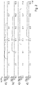
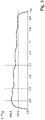
- each individual filling valve 12 leads to changing pressure conditions in the filling product feed line 18. This is due, among other things, to the hydraulic inductance of the fluid in the filling product supply line 18 is based. Accordingly, at the beginning of the filling process, when first a first filling valve 12 and then more and more filling valves 12 are opened, starting from an initial differential pressure, the differential pressure decreases more and more slowly, which correspondingly influences the volume flow through the already opened filling valves 12.
- the control loop between the individual filling valve 12 and the flow meter assigned to this filling valve 12 is too sluggish to reliably compensate for these volume flow fluctuations.
- the basis for the improved control process proposed here is precise knowledge of the filling valve 12 and, in particular, of the control valve used in each case.
- Knowledge of the relationship between the conductivity K V and the stroke H of the control valve plays a role here:
- a function of the conductance K V (H) of the control valve is determined for each opening position H of the control valve.
- the conductance K V is also referred to as the flow factor or flow coefficient of the control valve. It is a measure of the achievable throughput of a liquid or gas through the control valve, is given here in the unit ml/sec and can be interpreted as the effective cross-section.
- Each K V value only applies to the associated opening position H of the control valve.
- the filling product flow q(H) from the control valve is measured at this opening position H i and from this in the steady state the conductance K V is determined, for example by means of a measurement a measuring cell such as a load cell. This is carried out for a large number of discrete opening positions H i of the control valve.
- the differential pressure ⁇ p and the density p of the filling product flowing through the control valve must also be determined.
- the density p of the filling product is usually known or can be determined using known measurement methods.
- the density can be assumed to be approximately 1000 kg/m 3 , so that it then does not need to be changed for a large number of filling products to be filled.
- a compensating curve is determined by the respective conductances K V (H i ) determines a function of the conductance over the opening positions of the control valve.
- the regression curve can be determined, for example, by linear regression, the least squares method, a fit algorithm or other known methods for determining a regression curve from measured values. This determination and calculation is performed for various discrete values of the opening position Hi .
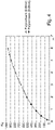
- a sixth-order polynomial for example, can be used as a regression curve, as is the case, for example, in figure 4 is shown, in which the conductance is plotted against the respective opening position of the control valve.
- a first range of values for the opening positions from 0 to 2 mm and a second range of values for the opening positions from 2 mm to 6 mm were used to determine the compensating curve.
- the discrete values 20 in the first value range and the discrete values 22 in the second value range were used to form the curve of the K V values 2 over the opening position H of the control valve to form a compensating curve using a 6th order polynomial.
- K V H c 6 * H 6 + c 5 * H 5 + c 4 * H 4 + c 3 * H 3 + c 2 * H 2 + c 1 * H + c 7
- c 1 to c 7 are the corresponding coefficients for fitting the function to the measured values.
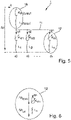
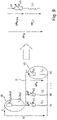
- K VInlet Conductance inflow
- K V1-n Conductance single filling valve
- L inlet Hydraulic inductance feed
- 1-n Hydraulic inductance filling valve
- ⁇ p differential pressure
- q flow rate inlet
- q1-n Flow rate filling valve
- the opening position or the degree of opening of the filling valve 12 influences the system variables KV1-n and L 1-n and thus indirectly the potential and flow variables.
- the filling product supply line 18 accordingly comprises a hydraulic inductance L supply and a conductance K V-supply , with which the behavior of the filling product supply line 18 can be described according to the electrical-fluidic analogy.
- the entire volume flow q which is supplied from the filling product reservoir provided, is supplied to the individual filling valves 12 accordingly via the filling product feed line 18 .
- each filling valve 12 is connected in parallel to one another and are all connected to the filling product supply line 18 .
- each filling valve 12 also has a hydraulic inductance L 1 and a conductance K V1 , by means of which the flow behavior of each filling valve 12 can be represented according to the electrical-fluidic analogy.
- the formula can be used for more complicated line geometries in infinitesimally small sections.
- the resulting individual inductances are then to be added up or integrated to form a total inductance.
- This mesh equation is now to be set up for each of the filling valves 12 of the respective filling product bottling plant 1, from which a complex differential equation system results accordingly.
- This differential equation system describes the mutual influence of the filling valves 12 when the filling valves 12 are connected in parallel given the differential pressure ⁇ p v dropping across these filling valves 12 .
- the differential pressure ⁇ p v can be determined in a simple manner in the filling product bottling plant 1 by means of appropriate pressure sensors.
- the pressure sensors have a very short response time, for example in the range of 1ms, and are sufficiently accurate. This results in a very quick measurement of the differential pressure ⁇ p v and thus the possibility of a quick determination of the resulting volume flow through the respective filling valve.
- the same pressure prevails at the filling valve outlet 14 of all filling valves 12 .
- This pressure can, for example, the ambient pressure in a free jet process or the Pressure of a defined applied bias in the container to be filled.
- the corresponding pressure at the filling valve outlet 14 is therefore known in principle and is equal to a first approximation for each filling valve 12 at the respective start of filling.
- the same pressure also prevails above the filling valves 12 in a first approximation. Accordingly, to simplify the method, an individual consideration of the individual filling valves 12 can be dispensed with.
- the measured differential pressure ⁇ p v corresponds to the differential pressure across all active control valves that are present in the corresponding parallel circuit.
- the volume flow q ( t , ⁇ p v ) calculated in this way based on the differential pressure ⁇ p v is then transferred to a controller or regulator in order to achieve appropriate control of the valve position of the respective control valve to maintain the specified target volume flow.
- the control which is carried out on the basis of the volume flow q ( t , ⁇ p v ) calculated based on the currently measured differential pressure ⁇ p v , can be modulated onto the remaining control and/or regulation steps of a higher-level system control.
- the remaining control and/or regulation behavior of the individual filling valve 12 is not changed as a result. Rather, the compensation via the volume flow q ( t , ⁇ p v ) calculated based on the currently measured differential pressure ⁇ p v achieves more precise compliance with the required volume flow profile, regardless of the number of filling valves 12 opened at the same time.
- the method for compensation can be used at the beginning and at the end of the respective filling operation until a steady equilibrium of the number of filling valves 12 opened in parallel has resulted in full operation.
- the method can also be continuously compensated during the entire filling operation to compensate for the opening position of all filling valves 12, taking into account the differential pressure ⁇ p v .
- a control valve 180 is provided in the filling product supply line 18, by means of which the common inflow to the separate individual filling valves 12 can be controlled.
- the filling valves 12 are not designed as control valves, but as simple switching valves (open/closed).
- control behavior of the filling valves 12 which is achieved in the above-described embodiments via the filling valves designed as control valves, can be taken over in this embodiment by the one control valve 180 arranged in the filling product feed line 18.
- the control valve 180 in the inlet 18 thus exhibits a behavior in which, at the start of production, it is initially adjusted to a lower conductance value K V and then the first filling valve 12 is opened.
- the conductance K V of the control valve 180 is then gradually increased synchronously with the increase in the number of open filling valves 12, so that each individual filling valve 12 sees the same differential pressure in principle.
- the pressure drop ⁇ p inlet is varied by means of the control valve 180 in the inlet, so that ⁇ p valve can be kept constant.
Landscapes
- Physics & Mathematics (AREA)
- Fluid Mechanics (AREA)
- Filling Of Jars Or Cans And Processes For Cleaning And Sealing Jars (AREA)
- Basic Packing Technique (AREA)
Claims (6)
- Procédé de remplissage d'un récipient avec un produit de remplissage dans une installation de remplissage de produit de remplissage présentant au moins deux soupapes de remplissage (12) montées parallèlement l'une à l'autre comme soupapes de régulation, avec les étapes :- le calcul d'une fonction du courant volumique q(t, Δpv ) pour au moins deux des soupapes de remplissage (12) montées parallèlement en fonction d'une pression différentielle Δpv diminuant par le biais des soupapes de remplissage (12) montées parallèlement ;- le calcul de la pression différentielle Δpv par le biais de toutes les soupapes de remplissage (12) montées parallèlement ;- le calcul du courant volumique q(t,Δpv } à travers au moins une des soupapes de remplissage (12) montées parallèlement sur la base de la pression différentielle calculée Δpv ; et- la régulation et/ou la commande d'au moins une soupape de remplissage (12) en fonction du courant volumique calculé q(t, Δpv ), dans lequel la régulation et/la commande d'au moins une soupape de remplissage (12) comporte une compensation de la position d'ouverture de la soupape de remplissage (12) en cas de pression différentielle Δpv se modifiant à l'aide du courant volumique actuel calculé q(t Δpv ).
- Procédé selon la revendication 1, caractérisé en ce que la régulation et/ou la commande de la soupape de remplissage (12) comporte la commande d'une position d'ouverture de la soupape de remplissage (12) à l'aide du courant volumique actuel q(t, Δpv ).
- Procédé selon la revendication 1 ou 2, caractérisé en ce que la régulation et/ou la commande d'au moins une soupape de remplissage (12) est réalisée en tenant compte d'un profil de courant volumique prédéfini pour le remplissage du récipient à remplir avec le produit de remplissage.
- Procédé selon l'une quelconque des revendications 1 à 3, caractérisé en ce que la régulation et/ou la commande d'au moins une soupape de remplissage (12) est réalisée en fonction du courant volumique calculé q(t, Δpv ) seulement au début et/ou à la fin du mode de remplissage respectif, de préférence jusqu'à ce qu'un équilibre stabilisé soit atteint au niveau des soupapes de remplissage (12) ouvertes simultanément.
- Procédé selon l'une quelconque des revendications 1 à 4, caractérisé en ce que la régulation et/ou la commande d'au moins une soupape de remplissage (12) est réalisée en fonction du courant volumique q(t, Δpv )calculé seulement si la régulation et/ou la commande résultante dépasse un seuil prédéfini.
- Procédé selon l'une quelconque des revendications précédentes, caractérisé en ce que la fonction du courant volumique q(t, Δpv ) est donnée en fonction de la pression différentielle Δpv


Priority Applications (1)
| Application Number | Priority Date | Filing Date | Title |
|---|---|---|---|
| SI201830815T SI3672903T1 (sl) | 2017-08-21 | 2018-08-20 | Postopek za polnjenje vsebnikov s polnilnim produktom |
Applications Claiming Priority (2)
| Application Number | Priority Date | Filing Date | Title |
|---|---|---|---|
| DE102017119069.4A DE102017119069A1 (de) | 2017-08-21 | 2017-08-21 | Verfahren zum Befüllen von Behältern mit einem Füllprodukt |
| PCT/EP2018/072416 WO2019038224A1 (fr) | 2017-08-21 | 2018-08-20 | Procédé de remplissage de contenants avec un produit de remplissage |
Publications (2)
| Publication Number | Publication Date |
|---|---|
| EP3672903A1 EP3672903A1 (fr) | 2020-07-01 |
| EP3672903B1 true EP3672903B1 (fr) | 2022-11-23 |
Family
ID=63371676
Family Applications (1)
| Application Number | Title | Priority Date | Filing Date |
|---|---|---|---|
| EP18759594.7A Active EP3672903B1 (fr) | 2017-08-21 | 2018-08-20 | Procédé pour remplir des récipients avec des produits |
Country Status (6)
| Country | Link |
|---|---|
| US (1) | US11377335B2 (fr) |
| EP (1) | EP3672903B1 (fr) |
| CN (1) | CN111247088B (fr) |
| DE (1) | DE102017119069A1 (fr) |
| SI (1) | SI3672903T1 (fr) |
| WO (1) | WO2019038224A1 (fr) |
Families Citing this family (3)
| Publication number | Priority date | Publication date | Assignee | Title |
|---|---|---|---|---|
| EP3705450B2 (fr) | 2019-03-08 | 2026-01-28 | Sidel Participations | Appareil et procédé de remplissage d'un contenant |
| DE102019125329A1 (de) | 2019-09-20 | 2021-03-25 | Krones Ag | Verfahren und Vorrichtung zum Befüllen eines Behälters mit einem Füllprodukt |
| DE102019135257A1 (de) * | 2019-12-19 | 2021-06-24 | Krones Ag | Vorrichtung zum Befüllen eines Behälters mit einem Füllprodukt |
Family Cites Families (11)
| Publication number | Priority date | Publication date | Assignee | Title |
|---|---|---|---|---|
| DE2727446A1 (de) * | 1977-06-18 | 1979-01-04 | Holstein & Kappert Maschf | Verfahren zum abfuellen von fluessigkeiten in behaelter |
| US4527593A (en) * | 1983-05-04 | 1985-07-09 | Campau Daniel N | Apparatus and system for filling one or more containers with a liquid to a predetermined level |
| IT1251941B (it) * | 1991-10-17 | 1995-05-27 | Nuovo Pignone Spa | Sistema perfezionato di comando dell'attuatore di una valvola di regolazione della portata. |
| JP2633820B2 (ja) * | 1995-06-16 | 1997-07-23 | ボッシュ包装機株式会社 | 液体の圧力充填方法 |
| EP0858018A1 (fr) * | 1997-02-06 | 1998-08-12 | Georg Fischer Rohrleitungssysteme AG | Méthode et dispositif pour la régulation du débit des fluides |
| DE10008426B4 (de) | 2000-02-23 | 2011-07-28 | KHS GmbH, 44143 | System sowie Verfahren zum Füllen von Behältern mit einem flüssigen Füllgut |
| DE102008037160A1 (de) * | 2008-08-08 | 2010-02-11 | Krones Ag | Versorgungsvorrichtung |
| US9428373B2 (en) | 2011-04-06 | 2016-08-30 | Mitsubishi Heavy Industries Food & Packaging Machine Co., Ltd. | Rotary-type filling machine and method for calculating filling quantity for rotary-type filling machine |
| US9658628B2 (en) * | 2013-03-15 | 2017-05-23 | Schneider Electric Buildings, Llc | Advanced valve actuator with true flow feedback |
| DE102014110161A1 (de) * | 2014-07-18 | 2016-01-21 | Krones Aktiengesellschaft | Verfahren zum Befüllen eines Behälters mit einem Füllprodukt mittels eines Proportionalventils |
| DE102015111536A1 (de) * | 2015-07-16 | 2017-01-19 | Khs Gmbh | Verfahren sowie Füllsystem zum Befüllen von Behältern |
-
2017
- 2017-08-21 DE DE102017119069.4A patent/DE102017119069A1/de not_active Withdrawn
-
2018
- 2018-08-20 US US16/641,165 patent/US11377335B2/en active Active
- 2018-08-20 CN CN201880068596.5A patent/CN111247088B/zh active Active
- 2018-08-20 SI SI201830815T patent/SI3672903T1/sl unknown
- 2018-08-20 WO PCT/EP2018/072416 patent/WO2019038224A1/fr not_active Ceased
- 2018-08-20 EP EP18759594.7A patent/EP3672903B1/fr active Active
Also Published As
| Publication number | Publication date |
|---|---|
| US20200198954A1 (en) | 2020-06-25 |
| CN111247088B (zh) | 2022-07-15 |
| US11377335B2 (en) | 2022-07-05 |
| SI3672903T1 (sl) | 2023-01-31 |
| CN111247088A (zh) | 2020-06-05 |
| WO2019038224A1 (fr) | 2019-02-28 |
| DE102017119069A1 (de) | 2019-02-21 |
| EP3672903A1 (fr) | 2020-07-01 |
Similar Documents
| Publication | Publication Date | Title |
|---|---|---|
| DE69000764T2 (de) | Vorrichtung zum fuellen von behaeltern mit abgewogenen mengen. | |
| EP2855002B1 (fr) | Procédé et dispositif pour mélanger au moins deux composants liquides | |
| DE3877815T2 (de) | Verfahren und vorrichtung zum messen von fluessigkeit. | |
| EP0038054B2 (fr) | Dispositif pour la régulation automatique d'un moulin à cylindres, comportant un contrôle d'alimentation de la matière à broyer | |
| DE60038228T2 (de) | Abgabevorrichtung und abgabeverfahren für viskoses material mit rückkoppelungsregelkreis | |
| EP2975486B2 (fr) | Procédé de remplissage d'un récipient avec un produit de remplissage a l'aide d'une soupape proportionnelle | |
| AT402916B (de) | Kransteuersystem | |
| DE69915374T2 (de) | Verfahren und vorrichtung zur regelung des druckes eines gasstromes | |
| AT519880B1 (de) | Druckregeleinrichtung für ein Kraftstoffverbrauchsmesssystem und Kraftstoffverbrauchsmesssystem | |
| WO1985001577A1 (fr) | Procede et installation de determination du debit d'un ecoulement de marchandises en vrac | |
| EP3672903A1 (fr) | Procédé de remplissage de contenants avec un produit de remplissage | |
| EP3498659B1 (fr) | Procédé et dispositif de remplissage d'un produit de remplissage | |
| DE60312107T2 (de) | Luftversorgungsvorrichtung für Düsenwebmaschine | |
| DE3540285A1 (de) | Verfahren und einrichtung zum regeln von turbokompressoren | |
| DE69317662T2 (de) | Kontrollsystem zur beschickung einer zentrifuge | |
| DE10151423A1 (de) | Vorrichtung zur Einstellung eines einen Bogentransport beeinflussenden Luftstroms in einer Druckmaschine und entsprechendes Verfahren | |
| EP2233227B1 (fr) | Bouchon en céramique ignifuge | |
| DE2611427C2 (fr) | ||
| DE10209435C1 (de) | Vorrichtung zum gleichzeitigen Befüllen mehrerer Behälter | |
| EP0121599A2 (fr) | Procédé et dispositif pour le transport pneumatique des particules fines | |
| CH699915B1 (de) | Betrieb einer pneumatischen Vorrichtung für die dosierte Abgabe einer Flüssigkeit und pneumatische Vorrichtung. | |
| DE2657986A1 (de) | Richtmaschine zum richten von blechen und flachmaterialien | |
| DE2831053C2 (de) | Brennstoff-Zuführeinrichtung für eine Brennkraftmaschine | |
| EP0548023A1 (fr) | Commande de débit d'une ligne de nettoyage | |
| EP3765216B1 (fr) | Groupe de refroidissement pour un dispositif de refroidissement laminaire |
Legal Events
| Date | Code | Title | Description |
|---|---|---|---|
| STAA | Information on the status of an ep patent application or granted ep patent |
Free format text: STATUS: UNKNOWN |
|
| STAA | Information on the status of an ep patent application or granted ep patent |
Free format text: STATUS: THE INTERNATIONAL PUBLICATION HAS BEEN MADE |
|
| PUAI | Public reference made under article 153(3) epc to a published international application that has entered the european phase |
Free format text: ORIGINAL CODE: 0009012 |
|
| STAA | Information on the status of an ep patent application or granted ep patent |
Free format text: STATUS: REQUEST FOR EXAMINATION WAS MADE |
|
| 17P | Request for examination filed |
Effective date: 20200221 |
|
| AK | Designated contracting states |
Kind code of ref document: A1 Designated state(s): AL AT BE BG CH CY CZ DE DK EE ES FI FR GB GR HR HU IE IS IT LI LT LU LV MC MK MT NL NO PL PT RO RS SE SI SK SM TR |
|
| AX | Request for extension of the european patent |
Extension state: BA ME |
|
| DAV | Request for validation of the european patent (deleted) | ||
| DAX | Request for extension of the european patent (deleted) | ||
| GRAP | Despatch of communication of intention to grant a patent |
Free format text: ORIGINAL CODE: EPIDOSNIGR1 |
|
| STAA | Information on the status of an ep patent application or granted ep patent |
Free format text: STATUS: GRANT OF PATENT IS INTENDED |
|
| INTG | Intention to grant announced |
Effective date: 20220614 |
|
| GRAS | Grant fee paid |
Free format text: ORIGINAL CODE: EPIDOSNIGR3 |
|
| GRAA | (expected) grant |
Free format text: ORIGINAL CODE: 0009210 |
|
| STAA | Information on the status of an ep patent application or granted ep patent |
Free format text: STATUS: THE PATENT HAS BEEN GRANTED |
|
| AK | Designated contracting states |
Kind code of ref document: B1 Designated state(s): AL AT BE BG CH CY CZ DE DK EE ES FI FR GB GR HR HU IE IS IT LI LT LU LV MC MK MT NL NO PL PT RO RS SE SI SK SM TR |
|
| REG | Reference to a national code |
Ref country code: GB Ref legal event code: FG4D Free format text: NOT ENGLISH |
|
| REG | Reference to a national code |
Ref country code: CH Ref legal event code: EP |
|
| REG | Reference to a national code |
Ref country code: DE Ref legal event code: R096 Ref document number: 502018011103 Country of ref document: DE |
|
| REG | Reference to a national code |
Ref country code: AT Ref legal event code: REF Ref document number: 1533056 Country of ref document: AT Kind code of ref document: T Effective date: 20221215 |
|
| REG | Reference to a national code |
Ref country code: IE Ref legal event code: FG4D Free format text: LANGUAGE OF EP DOCUMENT: GERMAN |
|
| REG | Reference to a national code |
Ref country code: LT Ref legal event code: MG9D |
|
| REG | Reference to a national code |
Ref country code: NL Ref legal event code: MP Effective date: 20221123 |
|
| PG25 | Lapsed in a contracting state [announced via postgrant information from national office to epo] |
Ref country code: SE Free format text: LAPSE BECAUSE OF FAILURE TO SUBMIT A TRANSLATION OF THE DESCRIPTION OR TO PAY THE FEE WITHIN THE PRESCRIBED TIME-LIMIT Effective date: 20221123 Ref country code: PT Free format text: LAPSE BECAUSE OF FAILURE TO SUBMIT A TRANSLATION OF THE DESCRIPTION OR TO PAY THE FEE WITHIN THE PRESCRIBED TIME-LIMIT Effective date: 20230323 Ref country code: NO Free format text: LAPSE BECAUSE OF FAILURE TO SUBMIT A TRANSLATION OF THE DESCRIPTION OR TO PAY THE FEE WITHIN THE PRESCRIBED TIME-LIMIT Effective date: 20230223 Ref country code: LT Free format text: LAPSE BECAUSE OF FAILURE TO SUBMIT A TRANSLATION OF THE DESCRIPTION OR TO PAY THE FEE WITHIN THE PRESCRIBED TIME-LIMIT Effective date: 20221123 Ref country code: FI Free format text: LAPSE BECAUSE OF FAILURE TO SUBMIT A TRANSLATION OF THE DESCRIPTION OR TO PAY THE FEE WITHIN THE PRESCRIBED TIME-LIMIT Effective date: 20221123 Ref country code: ES Free format text: LAPSE BECAUSE OF FAILURE TO SUBMIT A TRANSLATION OF THE DESCRIPTION OR TO PAY THE FEE WITHIN THE PRESCRIBED TIME-LIMIT Effective date: 20221123 |
|
| PG25 | Lapsed in a contracting state [announced via postgrant information from national office to epo] |
Ref country code: RS Free format text: LAPSE BECAUSE OF FAILURE TO SUBMIT A TRANSLATION OF THE DESCRIPTION OR TO PAY THE FEE WITHIN THE PRESCRIBED TIME-LIMIT Effective date: 20221123 Ref country code: PL Free format text: LAPSE BECAUSE OF FAILURE TO SUBMIT A TRANSLATION OF THE DESCRIPTION OR TO PAY THE FEE WITHIN THE PRESCRIBED TIME-LIMIT Effective date: 20221123 Ref country code: LV Free format text: LAPSE BECAUSE OF FAILURE TO SUBMIT A TRANSLATION OF THE DESCRIPTION OR TO PAY THE FEE WITHIN THE PRESCRIBED TIME-LIMIT Effective date: 20221123 Ref country code: IS Free format text: LAPSE BECAUSE OF FAILURE TO SUBMIT A TRANSLATION OF THE DESCRIPTION OR TO PAY THE FEE WITHIN THE PRESCRIBED TIME-LIMIT Effective date: 20230323 Ref country code: HR Free format text: LAPSE BECAUSE OF FAILURE TO SUBMIT A TRANSLATION OF THE DESCRIPTION OR TO PAY THE FEE WITHIN THE PRESCRIBED TIME-LIMIT Effective date: 20221123 Ref country code: GR Free format text: LAPSE BECAUSE OF FAILURE TO SUBMIT A TRANSLATION OF THE DESCRIPTION OR TO PAY THE FEE WITHIN THE PRESCRIBED TIME-LIMIT Effective date: 20230224 |
|
| P01 | Opt-out of the competence of the unified patent court (upc) registered |
Effective date: 20230523 |
|
| PG25 | Lapsed in a contracting state [announced via postgrant information from national office to epo] |
Ref country code: NL Free format text: LAPSE BECAUSE OF FAILURE TO SUBMIT A TRANSLATION OF THE DESCRIPTION OR TO PAY THE FEE WITHIN THE PRESCRIBED TIME-LIMIT Effective date: 20221123 |
|
| PG25 | Lapsed in a contracting state [announced via postgrant information from national office to epo] |
Ref country code: SM Free format text: LAPSE BECAUSE OF FAILURE TO SUBMIT A TRANSLATION OF THE DESCRIPTION OR TO PAY THE FEE WITHIN THE PRESCRIBED TIME-LIMIT Effective date: 20221123 Ref country code: RO Free format text: LAPSE BECAUSE OF FAILURE TO SUBMIT A TRANSLATION OF THE DESCRIPTION OR TO PAY THE FEE WITHIN THE PRESCRIBED TIME-LIMIT Effective date: 20221123 Ref country code: EE Free format text: LAPSE BECAUSE OF FAILURE TO SUBMIT A TRANSLATION OF THE DESCRIPTION OR TO PAY THE FEE WITHIN THE PRESCRIBED TIME-LIMIT Effective date: 20221123 Ref country code: DK Free format text: LAPSE BECAUSE OF FAILURE TO SUBMIT A TRANSLATION OF THE DESCRIPTION OR TO PAY THE FEE WITHIN THE PRESCRIBED TIME-LIMIT Effective date: 20221123 Ref country code: CZ Free format text: LAPSE BECAUSE OF FAILURE TO SUBMIT A TRANSLATION OF THE DESCRIPTION OR TO PAY THE FEE WITHIN THE PRESCRIBED TIME-LIMIT Effective date: 20221123 |
|
| REG | Reference to a national code |
Ref country code: DE Ref legal event code: R097 Ref document number: 502018011103 Country of ref document: DE |
|
| PG25 | Lapsed in a contracting state [announced via postgrant information from national office to epo] |
Ref country code: SK Free format text: LAPSE BECAUSE OF FAILURE TO SUBMIT A TRANSLATION OF THE DESCRIPTION OR TO PAY THE FEE WITHIN THE PRESCRIBED TIME-LIMIT Effective date: 20221123 Ref country code: AL Free format text: LAPSE BECAUSE OF FAILURE TO SUBMIT A TRANSLATION OF THE DESCRIPTION OR TO PAY THE FEE WITHIN THE PRESCRIBED TIME-LIMIT Effective date: 20221123 |
|
| PLBE | No opposition filed within time limit |
Free format text: ORIGINAL CODE: 0009261 |
|
| STAA | Information on the status of an ep patent application or granted ep patent |
Free format text: STATUS: NO OPPOSITION FILED WITHIN TIME LIMIT |
|
| 26N | No opposition filed |
Effective date: 20230824 |
|
| PG25 | Lapsed in a contracting state [announced via postgrant information from national office to epo] |
Ref country code: MC Free format text: LAPSE BECAUSE OF FAILURE TO SUBMIT A TRANSLATION OF THE DESCRIPTION OR TO PAY THE FEE WITHIN THE PRESCRIBED TIME-LIMIT Effective date: 20221123 |
|
| REG | Reference to a national code |
Ref country code: CH Ref legal event code: PL |
|
| PG25 | Lapsed in a contracting state [announced via postgrant information from national office to epo] |
Ref country code: MC Free format text: LAPSE BECAUSE OF FAILURE TO SUBMIT A TRANSLATION OF THE DESCRIPTION OR TO PAY THE FEE WITHIN THE PRESCRIBED TIME-LIMIT Effective date: 20221123 |
|
| PG25 | Lapsed in a contracting state [announced via postgrant information from national office to epo] |
Ref country code: LU Free format text: LAPSE BECAUSE OF NON-PAYMENT OF DUE FEES Effective date: 20230820 |
|
| GBPC | Gb: european patent ceased through non-payment of renewal fee |
Effective date: 20230820 |
|
| PG25 | Lapsed in a contracting state [announced via postgrant information from national office to epo] |
Ref country code: LU Free format text: LAPSE BECAUSE OF NON-PAYMENT OF DUE FEES Effective date: 20230820 Ref country code: CH Free format text: LAPSE BECAUSE OF NON-PAYMENT OF DUE FEES Effective date: 20230831 |
|
| REG | Reference to a national code |
Ref country code: BE Ref legal event code: MM Effective date: 20230831 |
|
| REG | Reference to a national code |
Ref country code: IE Ref legal event code: MM4A |
|
| PG25 | Lapsed in a contracting state [announced via postgrant information from national office to epo] |
Ref country code: IE Free format text: LAPSE BECAUSE OF NON-PAYMENT OF DUE FEES Effective date: 20230820 |
|
| PG25 | Lapsed in a contracting state [announced via postgrant information from national office to epo] |
Ref country code: GB Free format text: LAPSE BECAUSE OF NON-PAYMENT OF DUE FEES Effective date: 20230820 |
|
| PG25 | Lapsed in a contracting state [announced via postgrant information from national office to epo] |
Ref country code: IE Free format text: LAPSE BECAUSE OF NON-PAYMENT OF DUE FEES Effective date: 20230820 Ref country code: GB Free format text: LAPSE BECAUSE OF NON-PAYMENT OF DUE FEES Effective date: 20230820 |
|
| PG25 | Lapsed in a contracting state [announced via postgrant information from national office to epo] |
Ref country code: BE Free format text: LAPSE BECAUSE OF NON-PAYMENT OF DUE FEES Effective date: 20230831 |
|
| REG | Reference to a national code |
Ref country code: AT Ref legal event code: MM01 Ref document number: 1533056 Country of ref document: AT Kind code of ref document: T Effective date: 20230820 |
|
| PG25 | Lapsed in a contracting state [announced via postgrant information from national office to epo] |
Ref country code: AT Free format text: LAPSE BECAUSE OF NON-PAYMENT OF DUE FEES Effective date: 20230820 |
|
| PG25 | Lapsed in a contracting state [announced via postgrant information from national office to epo] |
Ref country code: AT Free format text: LAPSE BECAUSE OF NON-PAYMENT OF DUE FEES Effective date: 20230820 |
|
| PG25 | Lapsed in a contracting state [announced via postgrant information from national office to epo] |
Ref country code: BG Free format text: LAPSE BECAUSE OF FAILURE TO SUBMIT A TRANSLATION OF THE DESCRIPTION OR TO PAY THE FEE WITHIN THE PRESCRIBED TIME-LIMIT Effective date: 20221123 |
|
| PG25 | Lapsed in a contracting state [announced via postgrant information from national office to epo] |
Ref country code: BG Free format text: LAPSE BECAUSE OF FAILURE TO SUBMIT A TRANSLATION OF THE DESCRIPTION OR TO PAY THE FEE WITHIN THE PRESCRIBED TIME-LIMIT Effective date: 20221123 |
|
| REG | Reference to a national code |
Ref country code: DE Ref legal event code: R082 Ref document number: 502018011103 Country of ref document: DE Representative=s name: MAUCHER JENKINS PATENTANWAELTE & RECHTSANWAELT, DE |
|
| PG25 | Lapsed in a contracting state [announced via postgrant information from national office to epo] |
Ref country code: CY Free format text: LAPSE BECAUSE OF FAILURE TO SUBMIT A TRANSLATION OF THE DESCRIPTION OR TO PAY THE FEE WITHIN THE PRESCRIBED TIME-LIMIT; INVALID AB INITIO Effective date: 20180820 |
|
| PGFP | Annual fee paid to national office [announced via postgrant information from national office to epo] |
Ref country code: SI Payment date: 20250715 Year of fee payment: 8 |
|
| PG25 | Lapsed in a contracting state [announced via postgrant information from national office to epo] |
Ref country code: HU Free format text: LAPSE BECAUSE OF FAILURE TO SUBMIT A TRANSLATION OF THE DESCRIPTION OR TO PAY THE FEE WITHIN THE PRESCRIBED TIME-LIMIT; INVALID AB INITIO Effective date: 20180820 |
|
| PGFP | Annual fee paid to national office [announced via postgrant information from national office to epo] |
Ref country code: DE Payment date: 20250702 Year of fee payment: 8 |
|
| PGFP | Annual fee paid to national office [announced via postgrant information from national office to epo] |
Ref country code: IT Payment date: 20250722 Year of fee payment: 8 |
|
| PGFP | Annual fee paid to national office [announced via postgrant information from national office to epo] |
Ref country code: FR Payment date: 20250703 Year of fee payment: 8 |
|
| PG25 | Lapsed in a contracting state [announced via postgrant information from national office to epo] |
Ref country code: TR Free format text: LAPSE BECAUSE OF FAILURE TO SUBMIT A TRANSLATION OF THE DESCRIPTION OR TO PAY THE FEE WITHIN THE PRESCRIBED TIME-LIMIT Effective date: 20221123 |