EP3673144B1 - Vérin à cisaillement cinétique pour appareil de commande de pression de puits - Google Patents
Vérin à cisaillement cinétique pour appareil de commande de pression de puits Download PDFInfo
- Publication number
- EP3673144B1 EP3673144B1 EP19781923.8A EP19781923A EP3673144B1 EP 3673144 B1 EP3673144 B1 EP 3673144B1 EP 19781923 A EP19781923 A EP 19781923A EP 3673144 B1 EP3673144 B1 EP 3673144B1
- Authority
- EP
- European Patent Office
- Prior art keywords
- gate
- bore
- isolation ring
- piston
- ring cutter
- Prior art date
- Legal status (The legal status is an assumption and is not a legal conclusion. Google has not performed a legal analysis and makes no representation as to the accuracy of the status listed.)
- Active
Links
Images


Classifications
-
- E—FIXED CONSTRUCTIONS
- E21—EARTH OR ROCK DRILLING; MINING
- E21B—EARTH OR ROCK DRILLING; OBTAINING OIL, GAS, WATER, SOLUBLE OR MELTABLE MATERIALS OR A SLURRY OF MINERALS FROM WELLS
- E21B33/00—Sealing or packing boreholes or wells
- E21B33/02—Surface sealing or packing
- E21B33/03—Well heads; Setting-up thereof
- E21B33/06—Blow-out preventers, i.e. apparatus closing around a drill pipe, e.g. annular blow-out preventers
- E21B33/061—Ram-type blow-out preventers, e.g. with pivoting rams
- E21B33/062—Ram-type blow-out preventers, e.g. with pivoting rams with sliding rams
- E21B33/063—Ram-type blow-out preventers, e.g. with pivoting rams with sliding rams for shearing drill pipes
Definitions
- blowout preventers BOPs
- the disclosure relates to the field of well pressure control apparatus, namely, blowout preventers (BOPs). More specifically, the disclosure relates to actuating rams for so called “shear rams" which are used to close a BOP when there are tools, pipe or other devices in a subsurface well that prevent ordinary operation of other devices used to close a BOP.
- Blowout preventers used with, e.g., oil and gas wells, are provided to reduce risk of potentially catastrophic events known as a blowouts, where high well pressures and resulting uncontrolled flow from a subsurface formation into the well can expel tubular products (e.g., drill pipe and well casing), tools and fluid out of a well. Blowouts present a serious safety hazard to drilling crews, drilling rigs and the environment and can be extremely costly to control, repair and remediate resulting damage.
- BOPs have "rams" that opened and closed by actuators. The most common type of actuator is operated hydraulically to push closure elements across a through bore in a BOP housing (itself sealingly coupled to the well) to close the well.
- the rams have hardened steel shears to cut through a drill string or other tool or device which may be in the well at the time it is necessary to close the BOP.
- a limitation of many hydraulically actuated rams is that they require a large amount of hydraulic force to move the rams against the pressure inside the wellbore and in the case of shear rams subsequently to cut through objects in the through bore.
- hydraulically actuated rams An additional limitation of hydraulically actuated rams is that the hydraulic force is usually generated at a location away from the BOP (necessitating a hydraulic line from the pressure source to the rams), making the BOP susceptible to failure to close if the hydraulic line conveying the hydraulic force is damaged. Further limitations associated with hydraulically actuated rams may include erosion of cutting and sealing surfaces due to the relatively slow closing action of the rams in a flowing wellbore. Cutting through tool joints, drill collars, large diameter tubulars and off center pipe strings under heavy compression may also present problems for hydraulically actuated rams.
- a further limitation associated with hydraulically actuated shear ram BOPs is that the cutting blades are asymmetrical which leads to a splitting force being generated during the shearing action.
- pyrotechnic based BOPs such as disclosed in the foregoing publication is that the shearing element must cut through an isolation ring before it is possible to shear devices located in the through bore.
- the isolation ring is made as a heavy, thick element to exclude entry of well fluid under pressure into the pyrotechnic charge and shear storage volume at wellbore pressure.
- the presence of an isolation ring can significantly increase required shearing energy to ensure proper function of the shear ram(s).
- the isolation ring may generate additional debris upon shearing which may damage sealing arrangements within the BOP.
- US2010/0319906 describes a pyrotechnic based BOP entailing a piston and gate element propelled by a chemical propellant.
- a blowout preventer has a main body having a through bore.
- An isolation ring cutter is disposed in the passage inside the main body and configured for positioning with an opening on the isolation ring cutter centered about the through bore.
- a piston and a gate are disposed separated and spaced apart from the isolation ring cutter and configured for motion along the passage.
- a charge is located between the piston and an end cap. The charge is configured for activation to propel the piston and thus the gate along the passage into contact with the isolation ring cutter to propel the isolation ring cutter along the passage and across the through bore.
- the blowout preventer further comprises an energy absorbing element disposed in the housing proximate the main body.
- blowout preventer further comprises a restraint in the housing arranged to stop motion of the piston and the gate until gas pressure from the propellant charge reaches a selected threshold.
- the restraint comprises a shear pin.
- the isolation ring cutter comprises a cutting edge formed into a circumference of the opening.
- the blowout preventer further comprises a seal disposed in the main body and coaxial with the through bore, the seal arranged to close the through bore to fluid flow when the gate is moved to a position laterally adjacent to the seal.
- the pre-initiation spacing between the gate and isolation ring cutter may be between 1/8 and 1 ⁇ 2 of the diameter of the through bore, or may be greater than 1 ⁇ 2 the diameter of the through bore.
- a mass of the isolation ring cutter is less than 20 percent of the combined mass of the piston and the gate.
- a mass of the isolation ring cutter is less than 10 percent of the combined mass of the piston and the gate.
- the isolation ring cutter comprises at least one of steel and ceramic.
- the ceramic comprises metal carbide.
- a method of operating a blowout preventer having a main body with a through bore includes, actuating a charge located between a piston and an end cap to propel the piston and a gate into motion along a passage in the main body transverse to the through bore, wherein the piston and the gate are propelled from a position separated and spaced apart from an isolation ring cutter disposed in the passage inside the main body with an opening on the isolation ring cutter centered about the through bore, to a position where the gate contacts the isolation ring cutter to propel the isolation ring cutter along the passage; and allowing the propelled isolation ring cutter to move along the passage across the through bore.
- Some embodiments further comprise slowing the piston by contacting an energy absorbing element disposed in the housing proximate the main body.
- Some embodiments further comprise restraining motion of the piston and the gate until gas pressure from the propellant charge reaches a selected threshold.
- the selected threshold is set by selecting properties of a shear pin.
- the isolation ring cutter comprises a cutting edge formed into a circumference of the opening.
- a mass of the isolation ring cutter is less than 20 percent of the combined mass of the piston and the gate.
- a mass of the isolation ring cutter is less than 10 percent of the combined mass of the piston and the gate.
- the isolation ring cutter comprises at least one of steel and ceramic.
- the ceramic comprises metal carbide.
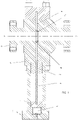
- FIG. 1 there is shown a sectioned elevational view of an example embodiment of a blowout preventer 100 (BOP) according the present disclosure.
- the blowout preventer 100 has a main body 5 having a through bore 7.
- the blowout preventer 100 also has a passage 8 that is oriented transversely to the through bore 7.
- An isolation ring cutter 4 fluidly seals the passage 8, which extends from the through bore 7 into a pressure housing 10.
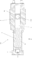
- the isolation ring cutter 4 is positioned inside the main body 5 and has an opening (see FIG. 2 , element 4A) centred about the through bore 7 prior to actuation of the BOP 100. See FIG. 2 for a plan view.
- a cutting edge see 4A in FIG.
- a piston 1 and a gate 3 are disposed in the pressure housing 10.
- the gate 3 may be a flat plate, e.g., as may be made from steel, shaped to enable longitudinal motion along the passage 8 and to act in the same manner as a gate in a gate valve to close the through bore 7 as will be further explained.
- a charge 9, which may be in the form of a heat and/or percussively initiated chemical propellant, is located between the piston 1 and an end cap 11 at the longitudinal end of the pressure housing 10 opposite the main body 5. The charge 9 may be initiated and combust or react to produce high pressure gases, which in turn propel the piston 1 and thus the gate 3 through the pressure housing 10 and into the isolation ring cutter 4.
- Kinetic energy from the piston 1 and the gate 3 are transferred to the isolation ring cutter 4 to propel the isolation ring cutter 4 along the passage 8 and across the through bore 7.
- the gate 3 and isolation ring cutter 4 may remain in intimate contact as they travel across the through bore 7 allowing the force from the expanding gases to continue to act through the piston 1 and gate 3 and onto the isolation ring cutter 4 during shearing to increase shearing effectiveness as will be described in greater detail below.
- the pre-initiation spacing between the gate 3 and isolation ring cutter 4 may be between 1/8 to 1 ⁇ 2 of the diameter of the through bore 7, or may be greater than 1 ⁇ 2 the diameter of the through bore 7.
- An arresting mechanism in the form of an energy absorbing element 2 is located inside the pressure housing 10 between the piston 1 and a bonnet 6.
- the energy absorbing element 2 which may be made from a crushable material, is adapted to absorb the kinetic energy of the piston 1 and the gate 3, as will be described in greater detail below.
- FIG. 2 a cross section view of the blowout preventer 100 prior to being activated.
- the charge 9, piston 1 and gate 3 are located on a first side of the through bore 7; the center line of the through bore 7 may be observed at CL.
- FIG. 2 also shows an initiator 12 which is adapted to activate the charge 9.
- FIG. 2 also shows the isolation ring cutter 4 fluidly sealing the passage 8 from the through bore 7.
- a through bore seal 13 may be disposed below the lower plane of the gate 3, which will be explained in more detail below.
- the energy absorbing element 2 may be located within the passage 8 on the same side of the through bore 7 as the piston 1 and gate 3.
- FIG. 3 shows a cross section view of the blowout preventer 100 where the charge 9 has not yet been activated by the initiator 12.
- the piston 1 and gate 3 are held in place against the forthcoming force of gas pressure from the charge 9 acting on the piston 1 by a restraint, for example a shear pin (not shown), until sufficient pressure from gases from the charge 9 has occurred after activation of the charge 9, that is, when pressure reaches a selected threshold.
- the restraint if only a single shear pin or similar device, may hold either the piston 1 or the gate 3.
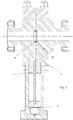
- FIG. 4 shows a cross section view of the blowout preventer 100 where a sufficient expansion of hot gases has occurred after activation of the charge 9 to break the shear pin (not shown).
- the piston 1 and gate3 are accelerating along the passage 8 toward the isolation ring cutter 4 and the through bore 7.
- kinetic energy is transferred from the piston 1 and gate 3 to the isolation ring cutter 4, thereby propelling the isolation ring cutter 4 into the through bore 7.
- the gate 3 may remain in intimate contact with the isolation ring cutter 4 as it traverses the through bore 7, thereby adding to the force the isolation ring cutter 4 is able to impart during shearing.
- Expanding gases behind the piston 1 may continue to act on the piston 1 during shearing as the isolation ring cutter 4 traverses the through bore 7. Thus additional force is provided beyond that produced by kinetic energy from the piston 1 and gate 3.
- the isolation ring cutter 4 will shear any wellbore tubulars, tools or other objects which are present in the through bore 7.
- Materials for the isolation ring cutter 4 may include strong and hard materials such as high strength steel and certain ceramics, such as metal carbides, e.g. tungsten carbide. Ceramics may be used for the entire structure of the isolation ring cutter 4 or may be applied as a coating to a high strength material, e.g., steel, substrate.
- the mating faces between the isolation ring cutter 4 and the gate 3 may be shaped to provide even loading.
- FIG. 4 shows that the geometry of the isolation ring cutter 4 (a flat face) and the corresponding geometry on the gate 3 (also a flat face) are complimentary, thus reducing point loading and allowing for more even stress distribution. It would also be possible to provide curved surfaces having similar radii on both the isolation ring cutter 4 and the gate 3 or a combination of flat surfaces and similar radius curved surfaces (not shown).
- FIG. 4 shows that in the present embodiment the isolation ring cutter 4 is much smaller in size than the gate 4 and the piston 1. This may be advantageous in reducing shock loading when the travelling assembly (the gate 4 and the piston 1) impacts the isolation ring cutter 4.
- the isolation ring cutter 4 has mass less than 20% of the mass of the (travelling assembly) piston 1 and gate 3 in combination. In some embodiments, the mass of the isolation ring cutter 4 it is less than 10% of the travelling assembly mass.
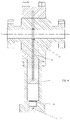
- FIG. 5 shows a cross section view of the blowout preventer 100.
- the isolation ring cutter 4 has sheared through anything that may have been located in the through bore 7.
- the front face of the piston 1 has now begun to contact the energy absorbing element 2, at such point in its minimum crush state.
- the isolation ring cutter 4 has now begun to contact the energy absorbent material (not shown separately) of the energy absorbing element 2 located in the passage in front of the isolation ring cutter 4.
- FIG. 6 shows a cross section view of the blowout preventer 100 where the body of energy absorbing material of the energy absorbing element 2 has crumpled to a predetermined amount, absorbing the kinetic energy of the piston 1 and the gate 3.
- the energy absorbent material (not shown separately) located in the passage 8 has also crumpled to a predetermined amount, absorbing the kinetic energy of the isolation ring cutter 4.
- the energy absorbing element 2 will retain the gate 3 in such a position that a sealing face (not shown) on the gate 3 is substantially aligned with the seal 13.
- the seal 1 will laterally press against the sealing face (not shown) on the gate 3, to stop the flow of well fluids through the through bore 7, thereby securely closing the well.
- well fluid pressure control operations for example choke and kill operations
- the blowout preventer 100 can be reopened, such as by retracting the gate 3 to open the through bore 7.
- hydraulic fluid 15 may be introduced between the front face of the piston 1 and the bonnet 6 to cause the piston 1 to retract away from the through bore 7.
- the gate 3 may optionally have a sealing face (not shown separately) which is adapted to engage with the through bore seal 13 to prevent passage of wellbore fluids from the through bore 7 into the passage 8.
- a sealing face (not shown) may optionally be present on at least one of a lower or upper surface portion of the gate 3. In an example embodiment, the sealing face (not shown) may be provided on at least a lower surface portion of the gate 3.
- a possible advantage of a BOP made according to the present disclosure is that the blow out preventer can be actuated without having to produce hydraulic forces to hydraulically push rams across the through bore to close off the through bore. Instead, the energy required to close the wellbore is contained in the charge in the blowout preventer where it is required.
- a possible advantage of holding the piston 1 and gate 3 in place by a shear pin is that this assists in the rapid acceleration of the piston 1 and gate 3 along the passage 8 once sufficient force has been generated by the expanding gases of the charge 9.
- a possible advantage of having the isolation ring cutter 4 fluidly sealing the passage 8 from the through bore 7 is that the piston 1 and gate 3 can accelerate along the passage 8 unhindered by well fluids or other liquids until the piston 1 and gate 3 contact the isolation ring cutter 4.
- a possible advantage of using an energy absorbing element 2 is that excess kinetic energy of the gate and piston is not directly transferred into a structural portion of the blowout preventer 100.
- a possible advantage of using an isolation ring cutter 4 in connection with the piston 1 and the gate 3 is that a separate isolation ring does not need to be sheared in addition to items that may be located in the through bore.
- An additional possible benefit is that there is no debris from shearing a separate isolation ring that may negatively impact seal performance.
Landscapes
- Life Sciences & Earth Sciences (AREA)
- Engineering & Computer Science (AREA)
- Geology (AREA)
- Mining & Mineral Resources (AREA)
- Physics & Mathematics (AREA)
- Environmental & Geological Engineering (AREA)
- Fluid Mechanics (AREA)
- General Life Sciences & Earth Sciences (AREA)
- Geochemistry & Mineralogy (AREA)
- Safety Valves (AREA)
- Perforating, Stamping-Out Or Severing By Means Other Than Cutting (AREA)
Claims (15)
- Bloc obturateur de puits (100) comprenant :un corps principal (5) ayant un alésage traversant (7) ;un passage (8) transversal à l'alésage traversant (7),une fraise annulaire d'isolement (4) disposée dans le passage (8) à l'intérieur du corps principal (5) et configurée pour être positionnée avec une ouverture (4A) sur la fraise annulaire d'isolement centrée autour de l'alésage traversant (7) ;un piston (1) et une porte (3) disposés séparés et espacés de la fraise annulaire d'isolement (4) et configurés pour se déplacer le long du passage (8) ;une charge (9) située entre le piston (1) et un bouchon d'extrémité (11) ; etla charge (9) configurée pour activation pour propulser le piston (1) et donc la porte (3) le long du passage (8) en contact avec la fraise annulaire d'isolement (4) pour propulser la fraise annulaire d'isolement le long du passage (8) et à travers l'alésage traversant (7).
- Bloc obturateur de puits (100) selon la revendication 1, comprenant en outre un élément d'absorption d'énergie (2)configuré pour absorber l'énergie cinétique du piston (1) et de la porte (3) après que le piston et la porte sont propulsés en mouvement.
- Bloc obturateur de puits (100) selon la revendication 2, dans lequel l'élément d'absorption d'énergie (2) est configuré pour se froisser lorsqu'il absorbe l'énergie cinétique du piston (1) et de la porte (3).
- Bloc obturateur de puits (100) selon la revendication 1, dans lequel la fraise annulaire d'isolement (4) comprend un bord coupant (4A) formé sur une circonférencede l'ouverture (4A) sur celle-ci.
- Bloc obturateur de puits (100) selon la revendication 1, comprenant en outre un joint (13) pour limiter l'écoulement de fluide entre l'alésage traversant (7) et le passage (8).
- Bloc obturateur de puits (100) selon la revendication 1, dans lequel un espacement de pré-amorçage entre la porte(3)et la fraise annulaire d'isolement (4) est compris entre 1/8 et 1/2 du diamètre de l'alésage traversant (7).
- Procédé de fonctionnement d'un bloc obturateur de puits (100) ayant un corps principal (5) avec un alésage traversant (7), comprenant :l'actionnement d'une charge (9) située entre un piston (1) et un bouchon d'extrémité (11) pour propulser le piston et une porte (3) en mouvement le long d'un passage (8) dans le corps principal (5) transversal à l'alésage traversant (7),dans lequel le piston (1) et la porte (3) sont propulsés à partir d'une position séparée et à distance d'unefraise annulaire d'isolement (4) disposée dans le passage (8) à l'intérieur du corps principal (5) avec une ouverture (4A) sur la fraise annulaire d'isolement centrée autour de l'alésage traversant (7), jusqu'à une position où la porte entre en contact avec la fraise annulaire d'isolement pour propulser la fraise annulaire d'isolement le long du passage (8) ; etpermettre à la fraise annulaire d'isolement (4) propulsée de se déplacer le long du passage (8) à travers l'alésage traversant (7).
- Procédé selon la revendication 7, dans lequel le bloc obturateur de puits (100) comprend un élément d'absorption d'énergie (2) configuré pour absorber l'énergie cinétique du piston (1) et de la porte (3) après que le piston et la porte sont propulsés en mouvement.
- Procédé selon la revendication 8, dans lequel l'élément d'absorption d'énergie (2) est configuré pour se froisser lorsqu'il absorbe l'énergie cinétique du piston (1) et de la porte (3).
- Procédé selon la revendication 7, comprenant en outre la limitation du mouvement de la porte (3) jusqu'à ce que la pression de gaz provenant de la charge (9) atteigne un seuil sélectionné.
- Procédé selon la revendication 7, dans lequel la fraise annulaire d'isolement (4) comprend un bord coupant (4A) formé sur une circonférence de l'ouverture (4A) sur celle-ci.
- Procédé selon la revendication 7, comprenant en outre le fait de permettre à la porte (3) de passer à travers l'alésage traversant (7) pour limiter l'écoulement de fluide dans l'alésage traversant.
- Procédé selon la revendication 7, dans lequel le bloc obturateur de puits (100) comprend un joint (13) pour limiter l'écoulement de fluide entre l'alésage traversant (7) et le passage (8).
- Procédé selon la revendication 7, dans lequel un espacement de pré-amorçage entre la porte (3) et la fraise annulaire (4) est compris entre 1/8 et 1/2 du diamètre de l'alésage traversant (7).
- Procédé selon la revendication 7, comprenant en outre le déplacement de la fraise annulaire d'isolement (4) à travers l'alésage traversant (7) pour couper un dispositif dans l'alésage traversant.
Applications Claiming Priority (2)
| Application Number | Priority Date | Filing Date | Title |
|---|---|---|---|
| US201862651929P | 2018-04-03 | 2018-04-03 | |
| PCT/US2019/025252 WO2019195200A1 (fr) | 2018-04-03 | 2019-04-01 | Vérin à cisaillement cinétique pour appareil de commande de pression de puits |
Publications (3)
| Publication Number | Publication Date |
|---|---|
| EP3673144A1 EP3673144A1 (fr) | 2020-07-01 |
| EP3673144A4 EP3673144A4 (fr) | 2021-05-05 |
| EP3673144B1 true EP3673144B1 (fr) | 2022-06-01 |
Family
ID=68101378
Family Applications (1)
| Application Number | Title | Priority Date | Filing Date |
|---|---|---|---|
| EP19781923.8A Active EP3673144B1 (fr) | 2018-04-03 | 2019-04-01 | Vérin à cisaillement cinétique pour appareil de commande de pression de puits |
Country Status (8)
| Country | Link |
|---|---|
| US (1) | US11028664B2 (fr) |
| EP (1) | EP3673144B1 (fr) |
| CN (1) | CN111201366B (fr) |
| AU (1) | AU2019249848B2 (fr) |
| CA (1) | CA3076531C (fr) |
| RU (1) | RU2740879C1 (fr) |
| SA (1) | SA520412291B1 (fr) |
| WO (1) | WO2019195200A1 (fr) |
Families Citing this family (5)
| Publication number | Priority date | Publication date | Assignee | Title |
|---|---|---|---|---|
| CA2984011C (fr) * | 2015-05-01 | 2019-04-09 | Kinetic Pressure Control Limited | Bloc d'obturation de puits |
| TW202018084A (zh) * | 2018-07-31 | 2020-05-16 | 加拿大商苜蓿股份有限公司 | 修飾之諾羅病毒vp1蛋白及包含修飾之諾羅病毒vp1蛋白之vlp |
| US20240263535A1 (en) * | 2023-02-02 | 2024-08-08 | Kinetic Pressure Control Ltd. | Cutters for severing objects in bores |
| US20250376906A1 (en) * | 2023-02-02 | 2025-12-11 | Kinetic Pressure Control Ltd. | Kinetic Blowout Preventer |
| US12247456B1 (en) | 2023-08-24 | 2025-03-11 | Schlumberger Technology Corporation | Blowout preventer system and method utilizing shear ram buttress |
Family Cites Families (26)
| Publication number | Priority date | Publication date | Assignee | Title |
|---|---|---|---|---|
| US3771601A (en) * | 1970-07-16 | 1973-11-13 | H Garrett | Well bore blocking method |
| US3766979A (en) * | 1972-04-20 | 1973-10-23 | J Petrick | Well casing cutter and sealer |
| US4305565A (en) * | 1980-04-07 | 1981-12-15 | Hydril Company | Variable position ram lock for blowout preventers |
| US4506858A (en) * | 1983-05-31 | 1985-03-26 | Otis Engineering Corporation | Wireline valve inner seal |
| US4840346A (en) * | 1985-04-11 | 1989-06-20 | Memory Metals, Inc. | Apparatus for sealing a well blowout |
| SU1263808A1 (ru) * | 1985-05-23 | 1986-10-15 | Волгоградский завод буровой техники | Способ герметизации усть скважины |
| US4638972A (en) * | 1985-07-18 | 1987-01-27 | Koomey | Valve apparatus |
| US5199683A (en) * | 1992-06-09 | 1993-04-06 | Baroid Technology, Inc. | Blowout preventer opening mechanism |
| US5501424A (en) * | 1994-02-09 | 1996-03-26 | Fmc Corporation | Wire cutting insert for gate valve |
| ATE327460T1 (de) * | 1998-08-13 | 2006-06-15 | Fike Corp | Ventil betätigt über gasdruckbehälter |
| US6454015B1 (en) * | 1999-07-15 | 2002-09-24 | Abb Vetco Gray Inc. | Shearing gate valve |
| GB0424401D0 (en) * | 2004-11-04 | 2004-12-08 | Bamford Antony S | HM blowout preventers |
| US7367396B2 (en) * | 2006-04-25 | 2008-05-06 | Varco I/P, Inc. | Blowout preventers and methods of use |
| CN101498201A (zh) * | 2009-03-13 | 2009-08-05 | 江苏咸中石油机械有限公司 | 捞油剪切密封防喷器 |
| US8567490B2 (en) * | 2009-06-19 | 2013-10-29 | National Oilwell Varco, L.P. | Shear seal blowout preventer |
| US20120055679A1 (en) * | 2010-09-08 | 2012-03-08 | Denzal Wayne Van Winkle | System and Method for Rescuing a Malfunctioning Subsea Blowout Preventer |
| AU2011320580B2 (en) * | 2010-10-29 | 2016-09-29 | SPEX Group Holdings Limited | Well emergency separation tool for use in separating a tubular element |
| MY165176A (en) * | 2011-01-04 | 2018-02-28 | Aker Subsea As | Gate valve assembly |
| NO332669B1 (no) * | 2011-05-16 | 2012-12-03 | Smart Installations As | Kutteanordning, sikkerhetsventil, fremgangsmate samt anvendelser for avkutting av en rorstrengrelatert gjenstand i en sikkerhetsventil for en bronn |
| US20130119288A1 (en) * | 2011-11-16 | 2013-05-16 | Vetco Gray Inc. | Gate shear valve |
| CN104411917B (zh) * | 2012-06-20 | 2018-01-09 | 国际壳牌研究有限公司 | 一种用于防喷器的电磁致动器 |
| US9249643B2 (en) * | 2013-03-15 | 2016-02-02 | National Oilwell Varco, L.P. | Blowout preventer with wedge ram assembly and method of using same |
| US8794333B1 (en) * | 2013-07-02 | 2014-08-05 | Milanovich Investments, L.L.C. | Combination blowout preventer and recovery device |
| US9752405B1 (en) * | 2014-01-06 | 2017-09-05 | Phyllis A. Jennings | Shear ram type blowout preventer |
| US10533667B2 (en) * | 2015-04-24 | 2020-01-14 | Cameron International Corporation | Shearing gate valve system |
| CA2984011C (fr) * | 2015-05-01 | 2019-04-09 | Kinetic Pressure Control Limited | Bloc d'obturation de puits |
-
2019
- 2019-04-01 EP EP19781923.8A patent/EP3673144B1/fr active Active
- 2019-04-01 AU AU2019249848A patent/AU2019249848B2/en active Active
- 2019-04-01 CA CA3076531A patent/CA3076531C/fr active Active
- 2019-04-01 WO PCT/US2019/025252 patent/WO2019195200A1/fr not_active Ceased
- 2019-04-01 CN CN201980004933.9A patent/CN111201366B/zh active Active
- 2019-04-01 RU RU2020113345A patent/RU2740879C1/ru active
-
2020
- 2020-02-28 US US16/804,206 patent/US11028664B2/en active Active
- 2020-06-21 SA SA520412291A patent/SA520412291B1/ar unknown
Also Published As
| Publication number | Publication date |
|---|---|
| US20200208489A1 (en) | 2020-07-02 |
| CA3076531A1 (fr) | 2019-10-10 |
| EP3673144A1 (fr) | 2020-07-01 |
| US11028664B2 (en) | 2021-06-08 |
| CN111201366B (zh) | 2022-06-14 |
| EP3673144A4 (fr) | 2021-05-05 |
| AU2019249848A1 (en) | 2020-03-26 |
| CA3076531C (fr) | 2022-06-21 |
| BR112020005954A2 (pt) | 2020-10-20 |
| RU2740879C1 (ru) | 2021-01-21 |
| SA520412291B1 (ar) | 2022-10-04 |
| WO2019195200A1 (fr) | 2019-10-10 |
| CN111201366A (zh) | 2020-05-26 |
| AU2019249848B2 (en) | 2021-12-02 |
Similar Documents
| Publication | Publication Date | Title |
|---|---|---|
| US11028664B2 (en) | Kinetic shear ram for well pressure control apparatus | |
| US11608703B2 (en) | Blowout preventer | |
| US11066892B2 (en) | Blowout preventer | |
| US11834922B2 (en) | Piston and gate assembly for kinetic pressure control apparatus ram | |
| EP3864254B1 (fr) | Dispositif de commande de pression à mécanisme de verrouillage de sécurité | |
| WO2021045985A1 (fr) | Dispositifs de coupe à poussoir à cisaillement cinétique pour appareil de commande de puits | |
| EP3830385B1 (fr) | Mâchoire à fermeture cinétique dotée d'un dispositif limiteur de pression | |
| US20250376906A1 (en) | Kinetic Blowout Preventer | |
| US20240263535A1 (en) | Cutters for severing objects in bores | |
| BR112020005954B1 (pt) | Preventor de erupção, e, método para fechar um poço |
Legal Events
| Date | Code | Title | Description |
|---|---|---|---|
| STAA | Information on the status of an ep patent application or granted ep patent |
Free format text: STATUS: THE INTERNATIONAL PUBLICATION HAS BEEN MADE |
|
| PUAI | Public reference made under article 153(3) epc to a published international application that has entered the european phase |
Free format text: ORIGINAL CODE: 0009012 |
|
| STAA | Information on the status of an ep patent application or granted ep patent |
Free format text: STATUS: REQUEST FOR EXAMINATION WAS MADE |
|
| 17P | Request for examination filed |
Effective date: 20200319 |
|
| AK | Designated contracting states |
Kind code of ref document: A1 Designated state(s): AL AT BE BG CH CY CZ DE DK EE ES FI FR GB GR HR HU IE IS IT LI LT LU LV MC MK MT NL NO PL PT RO RS SE SI SK SM TR |
|
| AX | Request for extension of the european patent |
Extension state: BA ME |
|
| A4 | Supplementary search report drawn up and despatched |
Effective date: 20210406 |
|
| RIC1 | Information provided on ipc code assigned before grant |
Ipc: E21B 33/06 20060101AFI20210329BHEP |
|
| RIN1 | Information on inventor provided before grant (corrected) |
Inventor name: GALLAGHER, BOBBY JAMES Inventor name: GALLAGHER, BILLY JACK |
|
| DAV | Request for validation of the european patent (deleted) | ||
| DAX | Request for extension of the european patent (deleted) | ||
| GRAP | Despatch of communication of intention to grant a patent |
Free format text: ORIGINAL CODE: EPIDOSNIGR1 |
|
| STAA | Information on the status of an ep patent application or granted ep patent |
Free format text: STATUS: GRANT OF PATENT IS INTENDED |
|
| GRAS | Grant fee paid |
Free format text: ORIGINAL CODE: EPIDOSNIGR3 |
|
| INTG | Intention to grant announced |
Effective date: 20220303 |
|
| RIN1 | Information on inventor provided before grant (corrected) |
Inventor name: GALLAGHER, BILLY JACK Inventor name: GALLAGHER, BOBBY JAMES |
|
| GRAA | (expected) grant |
Free format text: ORIGINAL CODE: 0009210 |
|
| STAA | Information on the status of an ep patent application or granted ep patent |
Free format text: STATUS: THE PATENT HAS BEEN GRANTED |
|
| AK | Designated contracting states |
Kind code of ref document: B1 Designated state(s): AL AT BE BG CH CY CZ DE DK EE ES FI FR GB GR HR HU IE IS IT LI LT LU LV MC MK MT NL NO PL PT RO RS SE SI SK SM TR |
|
| REG | Reference to a national code |
Ref country code: GB Ref legal event code: FG4D |
|
| REG | Reference to a national code |
Ref country code: AT Ref legal event code: REF Ref document number: 1495479 Country of ref document: AT Kind code of ref document: T Effective date: 20220615 Ref country code: CH Ref legal event code: EP |
|
| REG | Reference to a national code |
Ref country code: IE Ref legal event code: FG4D |
|
| REG | Reference to a national code |
Ref country code: DE Ref legal event code: R096 Ref document number: 602019015480 Country of ref document: DE |
|
| REG | Reference to a national code |
Ref country code: NO Ref legal event code: T2 Effective date: 20220601 |
|
| REG | Reference to a national code |
Ref country code: LT Ref legal event code: MG9D |
|
| REG | Reference to a national code |
Ref country code: NL Ref legal event code: MP Effective date: 20220601 |
|
| PG25 | Lapsed in a contracting state [announced via postgrant information from national office to epo] |
Ref country code: SE Free format text: LAPSE BECAUSE OF FAILURE TO SUBMIT A TRANSLATION OF THE DESCRIPTION OR TO PAY THE FEE WITHIN THE PRESCRIBED TIME-LIMIT Effective date: 20220601 Ref country code: LT Free format text: LAPSE BECAUSE OF FAILURE TO SUBMIT A TRANSLATION OF THE DESCRIPTION OR TO PAY THE FEE WITHIN THE PRESCRIBED TIME-LIMIT Effective date: 20220601 Ref country code: HR Free format text: LAPSE BECAUSE OF FAILURE TO SUBMIT A TRANSLATION OF THE DESCRIPTION OR TO PAY THE FEE WITHIN THE PRESCRIBED TIME-LIMIT Effective date: 20220601 Ref country code: GR Free format text: LAPSE BECAUSE OF FAILURE TO SUBMIT A TRANSLATION OF THE DESCRIPTION OR TO PAY THE FEE WITHIN THE PRESCRIBED TIME-LIMIT Effective date: 20220902 Ref country code: FI Free format text: LAPSE BECAUSE OF FAILURE TO SUBMIT A TRANSLATION OF THE DESCRIPTION OR TO PAY THE FEE WITHIN THE PRESCRIBED TIME-LIMIT Effective date: 20220601 Ref country code: ES Free format text: LAPSE BECAUSE OF FAILURE TO SUBMIT A TRANSLATION OF THE DESCRIPTION OR TO PAY THE FEE WITHIN THE PRESCRIBED TIME-LIMIT Effective date: 20220601 Ref country code: BG Free format text: LAPSE BECAUSE OF FAILURE TO SUBMIT A TRANSLATION OF THE DESCRIPTION OR TO PAY THE FEE WITHIN THE PRESCRIBED TIME-LIMIT Effective date: 20220901 |
|
| REG | Reference to a national code |
Ref country code: AT Ref legal event code: MK05 Ref document number: 1495479 Country of ref document: AT Kind code of ref document: T Effective date: 20220601 |
|
| PG25 | Lapsed in a contracting state [announced via postgrant information from national office to epo] |
Ref country code: RS Free format text: LAPSE BECAUSE OF FAILURE TO SUBMIT A TRANSLATION OF THE DESCRIPTION OR TO PAY THE FEE WITHIN THE PRESCRIBED TIME-LIMIT Effective date: 20220601 Ref country code: PL Free format text: LAPSE BECAUSE OF FAILURE TO SUBMIT A TRANSLATION OF THE DESCRIPTION OR TO PAY THE FEE WITHIN THE PRESCRIBED TIME-LIMIT Effective date: 20220601 Ref country code: LV Free format text: LAPSE BECAUSE OF FAILURE TO SUBMIT A TRANSLATION OF THE DESCRIPTION OR TO PAY THE FEE WITHIN THE PRESCRIBED TIME-LIMIT Effective date: 20220601 |
|
| PG25 | Lapsed in a contracting state [announced via postgrant information from national office to epo] |
Ref country code: NL Free format text: LAPSE BECAUSE OF FAILURE TO SUBMIT A TRANSLATION OF THE DESCRIPTION OR TO PAY THE FEE WITHIN THE PRESCRIBED TIME-LIMIT Effective date: 20220601 |
|
| PG25 | Lapsed in a contracting state [announced via postgrant information from national office to epo] |
Ref country code: SM Free format text: LAPSE BECAUSE OF FAILURE TO SUBMIT A TRANSLATION OF THE DESCRIPTION OR TO PAY THE FEE WITHIN THE PRESCRIBED TIME-LIMIT Effective date: 20220601 Ref country code: SK Free format text: LAPSE BECAUSE OF FAILURE TO SUBMIT A TRANSLATION OF THE DESCRIPTION OR TO PAY THE FEE WITHIN THE PRESCRIBED TIME-LIMIT Effective date: 20220601 Ref country code: RO Free format text: LAPSE BECAUSE OF FAILURE TO SUBMIT A TRANSLATION OF THE DESCRIPTION OR TO PAY THE FEE WITHIN THE PRESCRIBED TIME-LIMIT Effective date: 20220601 Ref country code: PT Free format text: LAPSE BECAUSE OF FAILURE TO SUBMIT A TRANSLATION OF THE DESCRIPTION OR TO PAY THE FEE WITHIN THE PRESCRIBED TIME-LIMIT Effective date: 20221003 Ref country code: EE Free format text: LAPSE BECAUSE OF FAILURE TO SUBMIT A TRANSLATION OF THE DESCRIPTION OR TO PAY THE FEE WITHIN THE PRESCRIBED TIME-LIMIT Effective date: 20220601 Ref country code: CZ Free format text: LAPSE BECAUSE OF FAILURE TO SUBMIT A TRANSLATION OF THE DESCRIPTION OR TO PAY THE FEE WITHIN THE PRESCRIBED TIME-LIMIT Effective date: 20220601 Ref country code: AT Free format text: LAPSE BECAUSE OF FAILURE TO SUBMIT A TRANSLATION OF THE DESCRIPTION OR TO PAY THE FEE WITHIN THE PRESCRIBED TIME-LIMIT Effective date: 20220601 |
|
| PG25 | Lapsed in a contracting state [announced via postgrant information from national office to epo] |
Ref country code: IS Free format text: LAPSE BECAUSE OF FAILURE TO SUBMIT A TRANSLATION OF THE DESCRIPTION OR TO PAY THE FEE WITHIN THE PRESCRIBED TIME-LIMIT Effective date: 20221001 |
|
| REG | Reference to a national code |
Ref country code: DE Ref legal event code: R097 Ref document number: 602019015480 Country of ref document: DE |
|
| PG25 | Lapsed in a contracting state [announced via postgrant information from national office to epo] |
Ref country code: AL Free format text: LAPSE BECAUSE OF FAILURE TO SUBMIT A TRANSLATION OF THE DESCRIPTION OR TO PAY THE FEE WITHIN THE PRESCRIBED TIME-LIMIT Effective date: 20220601 |
|
| PLBE | No opposition filed within time limit |
Free format text: ORIGINAL CODE: 0009261 |
|
| STAA | Information on the status of an ep patent application or granted ep patent |
Free format text: STATUS: NO OPPOSITION FILED WITHIN TIME LIMIT |
|
| PG25 | Lapsed in a contracting state [announced via postgrant information from national office to epo] |
Ref country code: DK Free format text: LAPSE BECAUSE OF FAILURE TO SUBMIT A TRANSLATION OF THE DESCRIPTION OR TO PAY THE FEE WITHIN THE PRESCRIBED TIME-LIMIT Effective date: 20220601 |
|
| 26N | No opposition filed |
Effective date: 20230302 |
|
| PG25 | Lapsed in a contracting state [announced via postgrant information from national office to epo] |
Ref country code: SI Free format text: LAPSE BECAUSE OF FAILURE TO SUBMIT A TRANSLATION OF THE DESCRIPTION OR TO PAY THE FEE WITHIN THE PRESCRIBED TIME-LIMIT Effective date: 20220601 |
|
| P01 | Opt-out of the competence of the unified patent court (upc) registered |
Effective date: 20230329 |
|
| REG | Reference to a national code |
Ref country code: DE Ref legal event code: R119 Ref document number: 602019015480 Country of ref document: DE |
|
| REG | Reference to a national code |
Ref country code: CH Ref legal event code: PL |
|
| PG25 | Lapsed in a contracting state [announced via postgrant information from national office to epo] |
Ref country code: LU Free format text: LAPSE BECAUSE OF NON-PAYMENT OF DUE FEES Effective date: 20230401 |
|
| REG | Reference to a national code |
Ref country code: BE Ref legal event code: MM Effective date: 20230430 |
|
| PG25 | Lapsed in a contracting state [announced via postgrant information from national office to epo] |
Ref country code: MC Free format text: LAPSE BECAUSE OF FAILURE TO SUBMIT A TRANSLATION OF THE DESCRIPTION OR TO PAY THE FEE WITHIN THE PRESCRIBED TIME-LIMIT Effective date: 20220601 |
|
| PG25 | Lapsed in a contracting state [announced via postgrant information from national office to epo] |
Ref country code: MC Free format text: LAPSE BECAUSE OF FAILURE TO SUBMIT A TRANSLATION OF THE DESCRIPTION OR TO PAY THE FEE WITHIN THE PRESCRIBED TIME-LIMIT Effective date: 20220601 Ref country code: LI Free format text: LAPSE BECAUSE OF NON-PAYMENT OF DUE FEES Effective date: 20230430 Ref country code: IT Free format text: LAPSE BECAUSE OF FAILURE TO SUBMIT A TRANSLATION OF THE DESCRIPTION OR TO PAY THE FEE WITHIN THE PRESCRIBED TIME-LIMIT Effective date: 20220601 Ref country code: FR Free format text: LAPSE BECAUSE OF NON-PAYMENT OF DUE FEES Effective date: 20230430 Ref country code: DE Free format text: LAPSE BECAUSE OF NON-PAYMENT OF DUE FEES Effective date: 20231103 Ref country code: CH Free format text: LAPSE BECAUSE OF NON-PAYMENT OF DUE FEES Effective date: 20230430 |
|
| REG | Reference to a national code |
Ref country code: IE Ref legal event code: MM4A |
|
| PG25 | Lapsed in a contracting state [announced via postgrant information from national office to epo] |
Ref country code: BE Free format text: LAPSE BECAUSE OF NON-PAYMENT OF DUE FEES Effective date: 20230430 |
|
| PG25 | Lapsed in a contracting state [announced via postgrant information from national office to epo] |
Ref country code: IE Free format text: LAPSE BECAUSE OF NON-PAYMENT OF DUE FEES Effective date: 20230401 |
|
| PG25 | Lapsed in a contracting state [announced via postgrant information from national office to epo] |
Ref country code: IE Free format text: LAPSE BECAUSE OF NON-PAYMENT OF DUE FEES Effective date: 20230401 |
|
| PG25 | Lapsed in a contracting state [announced via postgrant information from national office to epo] |
Ref country code: BG Free format text: LAPSE BECAUSE OF FAILURE TO SUBMIT A TRANSLATION OF THE DESCRIPTION OR TO PAY THE FEE WITHIN THE PRESCRIBED TIME-LIMIT Effective date: 20220601 |
|
| PG25 | Lapsed in a contracting state [announced via postgrant information from national office to epo] |
Ref country code: BG Free format text: LAPSE BECAUSE OF FAILURE TO SUBMIT A TRANSLATION OF THE DESCRIPTION OR TO PAY THE FEE WITHIN THE PRESCRIBED TIME-LIMIT Effective date: 20220601 |
|
| PG25 | Lapsed in a contracting state [announced via postgrant information from national office to epo] |
Ref country code: CY Free format text: LAPSE BECAUSE OF FAILURE TO SUBMIT A TRANSLATION OF THE DESCRIPTION OR TO PAY THE FEE WITHIN THE PRESCRIBED TIME-LIMIT; INVALID AB INITIO Effective date: 20190401 |
|
| PG25 | Lapsed in a contracting state [announced via postgrant information from national office to epo] |
Ref country code: HU Free format text: LAPSE BECAUSE OF FAILURE TO SUBMIT A TRANSLATION OF THE DESCRIPTION OR TO PAY THE FEE WITHIN THE PRESCRIBED TIME-LIMIT; INVALID AB INITIO Effective date: 20190401 |
|
| PG25 | Lapsed in a contracting state [announced via postgrant information from national office to epo] |
Ref country code: TR Free format text: LAPSE BECAUSE OF FAILURE TO SUBMIT A TRANSLATION OF THE DESCRIPTION OR TO PAY THE FEE WITHIN THE PRESCRIBED TIME-LIMIT Effective date: 20220601 |
|
| PGFP | Annual fee paid to national office [announced via postgrant information from national office to epo] |
Ref country code: GB Payment date: 20260312 Year of fee payment: 8 |
|
| PGFP | Annual fee paid to national office [announced via postgrant information from national office to epo] |
Ref country code: NO Payment date: 20260327 Year of fee payment: 8 |