EP3673232B1 - Steuerungssystem für ein schwimmbeckenreiniger - Google Patents
Steuerungssystem für ein schwimmbeckenreiniger Download PDFInfo
- Publication number
- EP3673232B1 EP3673232B1 EP18849210.2A EP18849210A EP3673232B1 EP 3673232 B1 EP3673232 B1 EP 3673232B1 EP 18849210 A EP18849210 A EP 18849210A EP 3673232 B1 EP3673232 B1 EP 3673232B1
- Authority
- EP
- European Patent Office
- Prior art keywords
- pool cleaner
- debris
- aquatic environment
- image
- control system
- Prior art date
- Legal status (The legal status is an assumption and is not a legal conclusion. Google has not performed a legal analysis and makes no representation as to the accuracy of the status listed.)
- Active
Links
Images


Classifications
-
- E—FIXED CONSTRUCTIONS
- E04—BUILDING
- E04H—BUILDINGS OR LIKE STRUCTURES FOR PARTICULAR PURPOSES; SWIMMING OR SPLASH BATHS OR POOLS; MASTS; FENCING; TENTS OR CANOPIES, IN GENERAL
- E04H4/00—Swimming or splash baths or pools
- E04H4/14—Parts, details or accessories not otherwise provided for
- E04H4/16—Parts, details or accessories not otherwise provided for specially adapted for cleaning
- E04H4/1654—Self-propelled cleaners
-
- G—PHYSICS
- G05—CONTROLLING; REGULATING
- G05D—SYSTEMS FOR CONTROLLING OR REGULATING NON-ELECTRIC VARIABLES
- G05D1/00—Control of position, course, altitude or attitude of land, water, air or space vehicles, e.g. using automatic pilots
- G05D1/0011—Control of position, course, altitude or attitude of land, water, air or space vehicles, e.g. using automatic pilots associated with a remote control arrangement
- G05D1/0038—Control of position, course, altitude or attitude of land, water, air or space vehicles, e.g. using automatic pilots associated with a remote control arrangement by providing the operator with simple or augmented images from one or more cameras located onboard the vehicle, e.g. tele-operation
-
- G—PHYSICS
- G05—CONTROLLING; REGULATING
- G05D—SYSTEMS FOR CONTROLLING OR REGULATING NON-ELECTRIC VARIABLES
- G05D1/00—Control of position, course, altitude or attitude of land, water, air or space vehicles, e.g. using automatic pilots
- G05D1/02—Control of position or course in two dimensions
- G05D1/0206—Control of position or course in two dimensions specially adapted to water vehicles
-
- G—PHYSICS
- G05—CONTROLLING; REGULATING
- G05D—SYSTEMS FOR CONTROLLING OR REGULATING NON-ELECTRIC VARIABLES
- G05D1/00—Control of position, course, altitude or attitude of land, water, air or space vehicles, e.g. using automatic pilots
- G05D1/02—Control of position or course in two dimensions
- G05D1/021—Control of position or course in two dimensions specially adapted to land vehicles
- G05D1/0231—Control of position or course in two dimensions specially adapted to land vehicles using optical position detecting means
- G05D1/0246—Control of position or course in two dimensions specially adapted to land vehicles using optical position detecting means using a video camera in combination with image processing means
-
- G—PHYSICS
- G05—CONTROLLING; REGULATING
- G05D—SYSTEMS FOR CONTROLLING OR REGULATING NON-ELECTRIC VARIABLES
- G05D1/00—Control of position, course, altitude or attitude of land, water, air or space vehicles, e.g. using automatic pilots
- G05D1/20—Control system inputs
- G05D1/24—Arrangements for determining position or orientation
- G05D1/243—Means capturing signals occurring naturally from the environment, e.g. ambient optical, acoustic, gravitational or magnetic signals
-
- G—PHYSICS
- G05—CONTROLLING; REGULATING
- G05D—SYSTEMS FOR CONTROLLING OR REGULATING NON-ELECTRIC VARIABLES
- G05D2109/00—Types of controlled vehicles
- G05D2109/30—Water vehicles
Definitions
- Most automatic pool cleaners include one or more components for driving the pool cleaner along a floor and sidewalls of a swimming pool.
- conventional pressure side cleaners and suction cleaners often use hydraulic turbine assemblies as drive systems to drive one or more wheels.
- Water supplied through the pool cleaner drives the turbine assemblies, which in turn, drive the wheels.
- Robotic pool cleaners have also been developed that utilize a motor instead of water to drive the pool cleaners.
- US 2014/015959 discloses a pool cleaning system that utilizes a powered robotic surface cleaning vehicle to travel adjacent water containing surfaces of a pool while submerged within the pool.
- a camera captures movement of the vehicle.
- a dry station serves the intermediary across a wide area network between the vehicle and a server which communicates with the portable electronic device.
- US 2014/015959 also discloses a pool cleaner control system to locate and remove debris from an aquatic environment, said system comprising a pool cleaner including a housing defined by one or more walls, an imaging device operably connected to the pool cleaner and configured to aquire at least one primary image of the aquatic environment, and a controller in communication with the imaging device, wherein the controller identifies candidate debris from the at least one primary image, determines an optimal cleaning pathway for each of the at least one primary image and navigates the pool cleaner to the candidate debris along the optimal cleaning pathway until the aquatic environment is clean.
- US 2014/015959 also discloses a method for determining a path of a pool cleaner including an imaging device, comprising the steps of controlling an imaging device to acquire one or more primary images from the imaging device and receiving the one or more primary images from the imaging device.
- WO 2014/151267 discloses swimming pool cleaners, systems and methods that generally include a swimming pool cleaner and a docking station.
- the swimming pool cleaner can include a battery and a debris container.
- the docking station generally includes an opening configured and dimensioned to at least partially receive the swimming pool cleaner. Upon receipt of the swimming pool cleaner in the opening of the housing, the docking station can automatically recharge the battery of the swimming pool cleaner and/or automatically clean the debris container of the swimming pool cleaner.
- WO 2014/004929 discloses a pool cleaner control system including a laser range finder with a first laser line generator, a second laser line generator, and a camera.
- the first laser line generator and the second laser line generator are positioned to emit parallel laser lines and the camera is positioned to capture an image of the laser lines projected on an object.
- the control system also includes a controller in communication with the laser range finder and configured to control operation of the laser line generators to emit the laser lines and to control the camera to capture the image.
- the controller is also configured to receive the image from the camera, calculate a pixel distance between the laser lines in the image, and calculate the physical distance between the camera and the object based on the pixel distance.
- WO 2016/137886 discloses a robotic pool cleaner and a control system of a robotic pool cleaner having an optical sensor positioned relative to an intake pathway of the robotic cleaner to monitor a flow of material through the intake pathway.
- An output of an optical sensor of the robotic pool cleaner can be monitored by the control system of the robotic pool cleaner to determine whether a detectable level of debris is flowing through the intake pathway.
- the robotic pool cleaner can perform one or more operations in response to a determination that a detectable level of debris is flowing through the intake pathway based on the output of the optical sensor.
- EP 2607573 discloses an automatic pool cleaner comprising a pump unit, a control unit and a sensor.
- the sensor is configured to detect foreign objects in the pool.
- the control unit is configured to activate the pump unit at a first power level which is less than full power when a foreign object is not detected by the sensor. It is further configured to activate the pump unit at a second power level, which is greater than the first power level, in response to a signal from the sensor unit indicating the detection of a foreign object.
- An object of the invention is to provide a pool cleaner control system to locate and remove debris from an aquatic environment.
- a pool cleaner control system to locate and remove debris from an aquatic environment as defined in claim 1.
- the controller can be further configured to create a secondary image from the at least one primary image, the secondary image being the at least one primary image with enhanced contrast, binarize the secondary image to create a tertiary image, wherein black and white contrast is created within the tertiary image, and filter out noise and artifacts from the tertiary image to identify objects to be removed from the aquatic environment.
- the controller can be further configured to utilize historical data of previous images including a particular object to determine whether the particular object is non-debris or candidate debris for removal.
- the imaging device can be further configured to acquire one or more images of the aquatic environment continuously.
- the imaging device can be a camera.
- the invention is directed to a pool cleaner control system to locate and remove debris from an aquatic environment.
- the pool cleaner control system comprises an imaging device configured to be coupled on a housing of a pool cleaner, and a controller in communication with the imaging device.
- the controller is configured to control the imaging device to acquire at least one primary image from the imaging device, receive the at least one primary image from the imaging device, create a secondary image from the at least one primary image, the secondary image being the at least one primary image with enhanced contrast, binarize the secondary image to create a tertiary image, wherein black and white contrast is created within the tertiary image, filter out noise and artifacts from the tertiary image to identify objects to be removed from the aquatic environment, track the objects to be removed from the aquatic environment, and determine which of the objects to be removed from the aquatic environment should be removed next.
- the secondary image can be a linear combination of a first percentage of a saturation channel and a second percentage of a blue channel. Each pixel of the linear combination may have a value that represents a brightness characteristic of the secondary image.
- the controller can be further configured to binarize the secondary image by changing each pixel above a threshold value to white and each pixel below the threshold value to black.
- the threshold value can be between about 100 to about 200.
- a user can determine the threshold value based on the aquatic environment. Noise and artifacts smaller than a threshold size can be filtered out of the tertiary image.
- the threshold size can be about 5 millimeters.
- the controller can be further configured to analyze movement of the objects in the aquatic environment to determine if the objects are non-debris or candidate debris for removal from the aquatic environment.
- the controller can be further configured to navigate the pool cleaner to remove candidate debris from the aquatic environment.
- a method of determining a path for a pool cleaner including an imaging device, the method being as defined in claim 12.
- the imaging device may acquire one or more primary images of the aquatic environment continuously and the imaging device may be a camera.
- Embodiments of the invention provide a pool cleaner control system comprising a pool cleaner for operation in enclosed aquatic environments. More specifically, embodiments of the invention provide control algorithms for operation of an autonomous robotic pool cleaner for operation in aquatic environments, for example, swimming pool and/or spa environments. The control algorithms utilize images or videos to determine target or candidate debris for removal. The control algorithm allows the pool cleaner to target and collect debris, rather than roaming aimlessly and randomly throughout the aquatic environment, thereby traversing and cleaning the entire aquatic environment in a shorter period of time.
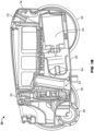
- FIGS. 1A and 1B illustrate an exemplary pool cleaner 20 that may implement the control algorithms disclosed herein.
- the pool cleaner 20 may include a housing 22 having a plurality of walls, for example, a top wall 24, a bottom wall 26, a first side wall 28, a second side wall 30, a front wall 32, and a rear wall 34, that all form a generally rectangular shape.
- the housing 22 may have any suitable number of walls and/or may have any suitable shape. While directional terminology is utilized herein (e.g., front, rear, forward, backward, etc.), such terminology is used to describe components or features in relation to one another and is not intended to be limited.
- the walls 32, 34 are described as being front and rear walls, but one skilled in the art will understand that the robotic pool cleaner 20 is capable of moving in a first direction in which the front wall 32 is facing a direction of travel, but the pool cleaner 20 may also be reversed such that the rear wall 34 is facing a direction of travel.
- the pool cleaner 20 includes a plurality of wheels, for example, a set of front wheels 40 and a set of rear wheels 42, each of which are driven by a drive system (not shown).
- a drive system (not shown).
- One front wheel 40 and one rear wheel 42 are operatively coupled to the first side wall 28 and one front wheel 40 and one rear wheel 42 are operatively coupled to the second side wall 30.
- Each of the wheels 40, 42 is driven by a drive system.
- the drive system may include, for example, a plurality of axles, gears, and/or other components that are operatively connected to, for example, a motor 44 that provides rotational energy to the axles, gears, and/or other components.
- the pool cleaner 20 may be pressure or suction driven, in which case, the pool cleaner 20 may include a turbine or other fluid directing device that controls a flow of water through the pool cleaner 20 to rotate the wheels 40, 42.
- the pool cleaner 20 may include two wheels, three wheels, or no wheels at all. In embodiments with no wheels, the pool cleaner 20 may traverse the aquatic environment via elongate treads, tracks, or other components that facilitate locomotion.
- the pool cleaner 20 may additionally include a front set of scrub brushes 50 and/or a rear set of scrub brushes (not shown) that assist in moving debris from a surface to be cleaned into an inlet 52 that is positioned behind the front set of scrub brushes 50 and in front of the rear set of scrub brushes.
- the scrub brushes may also be provided as a single brush as opposed to two discrete sections.
- debris and water are pulled through the inlet 52, into an inlet tube 54, and into a filter canister 56.
- the filter canister 56 collects debris and the water (without debris) is exhausted from the pool cleaner 20, for example, through one or more outlets 60 in the top wall 24 of the pool cleaner 20. In other embodiments, the one or more outlets may be positioned in any wall of the pool cleaner 20.
- the pool cleaner 20 may include a debris bag (not shown), or other internal or external debris capturing element.
- the pool cleaner 20 may further include a control module or system 100 that includes a controller 102 and other components, as discussed in more detail below, for operating the pool cleaner 20.
- the control algorithms may be implemented within the control module or system 100 and may operate one or more features and/or components of the pool cleaner 20 and/or the control module or system 100 may receive feedback from one or more components to operate the control algorithms to operate the pool cleaner 20 or to operate other components, functions, and/or features of the pool cleaner 20.
- One or more elements of the control system 100 may be provided in a substantially water tight enclosure.
- the control system 100 may include the controller 102, such as a central processing unit (“CPU”), a graphics processing unit (“GPU”), or both, a processor 104, memory 105, a storage medium 106 (e.g., a database (not shown)), and/or any other suitable components (e.g., an input/output device, a display unit, a network interface device, a disk drive, etc.).
- the processor 104 may be, for example, a microprocessor, a microcontroller, digital signal processor, or any other suitable processor.
- the processor 104 is communicatively coupled to the memory 105.
- the memory 105 may be embodied as any type of suitable computer memory device, including fixed and/or removable memory devices (e.g., volatile memory such as a form of random access memory or a combination of random access memory and read-only memory, such as memory cards, e.g., SD cards, memory sticks, hard drives, and/or others).
- Program code for example, the control algorithms disclosed herein, may be stored within the memory 105 and/or on the storage medium 106.
- the program code can be executed by the processor 104 to perform various operations, as will be discussed in more detail below.
- the control system 100 may further include any number of suitable components for providing feedback to the controller 102 and/or to which the control system provides instructions.
- Exemplary components that provide feedback or information to the control system 100 include, but are not limited to, one or more imaging devices 110 configured to capture video or images of the aquatic environment (for example, one or more of a camera or image sensor, a video camera, and/or any other suitable imaging device).
- one or more imaging devices may be mounted on the housing 22 of the pool cleaner 20, for example, at a front edge.
- the imaging device may be mounted on other portions of the pool cleaner 20 and extend upwardly from the top wall 24.
- the imaging device is designed to be positioned in a location where debris in the aquatic environment may be sensed and recorded.
- the imaging device 110 is designed to capture images of objects submerged within the aquatic environment.
- the imaging device may be mounted on the outer surface of the housing 22 of the pool cleaner 20.
- the imaging device 110 is mounted inside the housing 22 of the pool cleaner 20.
- the imaging device 110 is mounted on a handle of the pool cleaner 20.
- the imaging device is a camera and includes an image sensor.
- the camera is manufactured by Omnivision Technologies (Santa Clara, CA) and is provided under the model OV09732-H35A.
- the camera and/or the image sensor may be provided in a waterproof case (not shown). Data from the camera and/or the image sensor may be processed via Raspberry Pi Compute Module 3 with custom written software for image processing.
- the control system 100 may also include one or more gyroscopes 112, one or more tilt sensors 114, one or more accelerometers (not shown), one or more compasses 118, one or more other sensors 120, one or more inclinometers (not shown), or any other components that can provide feedback, for example, about the pool cleaner 20 and/or the environment around the pool cleaner 20.
- the controller 102 is capable of sending instructions to the imaging device 110, for example, to change an angle or viewing area of the imaging device 110 or to perform other functions.
- the controller 102 may be in communication with the imaging device 110 and may also send instructions to the imaging device 110 to continuously collect images of an aquatic environment.
- the controller 102 may also send instructions to the motor 44 to control operation of the pool cleaner 20, to a directional control 124 to control movement of the pool cleaner 20, and/or to any other components of the pool cleaner 20 to control any operation of the pool cleaner 20.
- the controller 102 may also receive data from any of the components of the pool cleaner 20, for example, regarding function of those components (e.g., fault or other conditions).
- the control module or system 100 may be further connected to a network (not shown), such that the control module or system 100 can communicate with remote devices, for example a computer, a mobile device, control modules or systems of other pool cleaners, or any other suitable devices. In this manner, instructions may be provided to the control module or system 100 to control various aspects of the pool cleaner 20.
- a mobile device e.g., by means of an application on the mobile device
- the control system 100 implements one or more algorithms that are intended to optimize cleaning paths, trajectories, or routes within an aquatic environment, for example a pool, by identifying specific locations of debris within the aquatic environment and determining a best path to take based on size and location of debris along each potential path and a smoothness of each potential path.
- the control system 100 continuously evaluates different paths and takes the best path at each evaluation until the entire aquatic environment is clean or until the pool cleaner 20 is turned off. In this manner, the time necessary to clean the aquatic environment is much less than conventional pool cleaners.
- the imaging device 110 is constantly collecting images of the aquatic environment (e.g., at 2 images per second, at 5 images per second, at 10 images per second, at more than 10 images per second, or any other suitable interval). In some embodiments, the imaging device 110 acquires at least one primary image of the aquatic environment. The controller 102 receives the at least one primary image from the imaging device 110.
- the algorithm of FIG. 3 identifies any number of candidate (or potential) paths it may take, identifies all debris objects on each candidate path, scores each path as a function of debris, applies penalties (as discussed more below), and chooses the candidate path with the best path score.
- the algorithm performs these steps for each image that is collected, which means that a different path could be chosen at any point in time.
- the algorithm creates a secondary image with enhanced contrast from the primary image, binarizes the secondary image to create a tertiary image with black and white contrast, filters out noise and artifacts from the tertiary image to identify objects to be removed from the aquatic environment, tracks the objects to be removed from the aquatic environment and determines in what order the objects may be removed from the aquatic environment.
- a white balance and gain adjustment of the imaging device 110 is performed dynamically, which assists in compensating for varying environmental conditions, for example, differing degrees of brightness (e.g., bright sunny days versus indoor pools, etc.).
- saturation FIG. 4
- blue channels FIG. 5
- a linear combination of saturation and blue channels is thereafter created, as seen in FIG. 6 .
- the result of the linear combination of the saturation and blue channels of the image is an image with enhanced contrast.
- a first designated percentage is assigned to the saturation channel extracted from each image.
- a second designated percentage is assigned to the blue channel.
- a first designated percentage of the saturation channel is combined with a second designated percentage of the blue channel, with a total of the first and second designated percentages being 100%, thereby creating the linear combination.
- the linear combination image is binarized. More particularly, each pixel in the linear combination image has a value (of 0 to 255) that represents its brightness. When the linear combination image is binarized, each pixel above a threshold is changed to white and each pixel below the threshold is changed to black. In some embodiments, when the secondary image is binarized, a tertiary image is created having black and white contrast. In some embodiments, the threshold is between about 100 and about 200. In some embodiments, the threshold is about between about 125 and about 175. While particular thresholds are disclosed herein, it should be understood that the threshold is dynamic for different portions of one image and from image to image. More particularly, there is a local background correction that is performed in order to determine a more optimal threshold value for different regions within one image. The background correction feature assists in equalizing sections within an image that contain different regions having different characteristics (e.g., bright and dark areas).
- the threshold may be customizable, for example, the pool cleaner 20 may include a user interface or may be programmable through, for example, an application on a mobile device, whereby a user may select a threshold size.
- the user may input, for example, through a user interface, a pool surface type (e.g., vinyl, concrete, etc.) and the control algorithm 200 automatically sets the thresholds (and/or additional filters, weights, and/or other parameters used in other processing steps).
- the control algorithm 200 may detect a pool surface type and/or environmental conditions and automatically adjusts the threshold and/or other parameters. In this manner, based on the particular aquatic environment, a user may select a different threshold.
- the binarization creates a binarized image, as seen in FIG. 7 , and provides for further contrast of debris 152 from the structural environment 150, which can assist in isolating debris 152 (shown in white in FIG. 7 ) and also assists in increasing the efficiency of later mathematical operations (e.g., in calculating a path score), as discussed in more detail below.
- transient noise and other artifacts are filtered out of the binarized image. More particularly, objects smaller than a threshold size are filtered out of the binarized image and are, thus, changed to black in the binarized image. As seen in the difference between FIGS. 7 and 8 , smaller objects 156 (see FIG. 7 ) have been filtered out (turned to black) in the binarized image to create a filtered image ( FIG. 8 ).
- the threshold size depends on the pool surface type and/or sensor resolution. For example, with a Pebble Tec ® surface, the threshold size may be about 5 millimeters. In aquatic environments utilizing concrete or vinyl, a much lower threshold size may be utilized.
- the threshold size may be customizable, for example, the pool cleaner 20 may include a user interface or may be programmable through, for example, an application on a mobile device, whereby a user may select a threshold size. In this manner, based on the particular aquatic environment, a user may select a different threshold size. For example, in a situation where the aquatic application includes a design on a surface of the aquatic application, the threshold size may be set to be larger than in an aquatic environment with no design.
- Removal of smaller objects helps to remove artifacts, such as textured pool surfaces, pool designs or finishes (e.g., Pebble Tec ® , etc.), spots created by water surface movement, or any other non-debris items within the aquatic environment.
- the removal of smaller objects also removes noise, for example, electrical noise in the imaging device (i.e., errors in the signals).
- the control algorithm removes anything from the binarized image that could be confused as being debris, but is not debris.
- the real-world size of debris may be determined by using a standard checkerboard calibration algorithm.
- objects are tracked utilizing the filtered image (of FIG. 8 ).
- FIG. 9 As the pool cleaner 20 moves forward, it would be expected that larger objects, such as first object 160 and second object 162 of FIG. 9 , would move downward and to the left in each subsequent captured image (after steps 202, 204, and 206 of FIG. 3 ). This expectation can be utilized to distinguish between actual debris and transient noise and artifacts.
- An example tracking operation of objects is depicted in FIG. 10 . In FIG. 10 , the first tracked object 160 is shown in red and the second tracked object 162 is shown in blue (both from FIG. 9 ).
- the circles for each tracked object represent the actual positions of the tracked objects and the stars for each tracked object represent a projected or anticipated position (sometime in the future) for each of the tracked objects.
- the original path is shown as 160a with the projected path of the first tracked object 160 shown labeled 160a.
- the first tracked object 160 may not follow the projected path.
- the first tracked object 160 does not follow the projected path and, instead, veers of course to the position indicated by 160b and a new projected path is calculated (as shown by the star labeled 160b).
- the control algorithms used in embodiments of the present invention determine whether the shift off the projected or anticipated path warrants elimination of the tracked object as debris or retention of the tracked object as debris.
- Tracked objects are then evaluated at step 210 of FIG. 3 . If, as seen in FIG. 11 , a tracked object appears to be moving along a consistent or expected trajectory, the track or path of the tracked object is identified as being a high quality track, for example, as seen with Tracked Object A. If data for a tracked object is missing, such that it is possible that the control system has picked up data for more than one object or picked up data for something that is not debris, the track or path for the tracked object is discarded, for example, as seen with Tracked Object B.
- the tracked object is likely not debris, as it is likely not a static object on a surface of the pool, and thus, the track or path for the tracked object is discarded, for example, as seen with Tracked Object C.
- This method of removing tracked objects with an erratic track or path assists in removing effects caused by, for example, erratic sun spots from surface ripples and other lighting effects. If a tracked object is moving too much in the aquatic environment, it is possible that the tracked object is still debris, but is moving enough that its track or path is removed. In this case, if the tracked object remains in the aquatic environment, the tracked object may be again recognized as potential debris, but the control algorithm may determine it is different from the original tracked object and will begin tracking it as a separate object.
- FIGS. 12 and 13 depict the result of the evaluating and removal (or retention) of various tracks or paths for tracked objects. More particularly, FIG. 12 depicts all tracks (in various colors throughout the image) and FIG. 13 depicts a vetted version of the image of FIG. 12 with various tracks or paths removed (through the evaluation step 210 of FIG. 3 ). In this manner, only candidate debris remains, the candidate debris representing objects to the control system 100 and is identified as debris that need to be removed.
- the control algorithm determines which path to take to remove remaining debris (i.e., candidate debris) at step 212 and navigates the pool cleaner 20 along the selected path to the candidate debris at step 214. The determination of which path or trajectory to take at step 212 will be discussed in more detail below.
- the step of determining which path or trajectory to take and thus, which candidate debris to remove next is evaluated at step 212 of FIG. 3 .
- the path score is a mathematical formulation that determines the best path, trajectory, or route to take in order to collect candidate debris.
- the score is based in part on a current location of the pool cleaner 20 and the locations of the candidate debris in the field of view of the imaging device 110.
- the path score is calculated for each potential path.
- the control algorithm is continuously making these path score calculations (for each image that is taken and manipulated per steps 202 through 210 of FIG. 3 ) to determine whether to stay on the current path or change its course to a different path.
- f ( A i ) represents a size and density of a candidate piece of debris, with A i representing the size and density of the candidate piece of debris, ⁇ being a characteristic size scale, and k being a term that adjusts the priority of large debris.
- k k is a real number.
- For k 1, there will be a linear scaling of size information.
- ⁇ is a constant that is selected to be a typical characteristic size for debris removal.
- ⁇ is only relevant for k > 1.
- objects with an area ⁇ ⁇ will be penalized.
- Both k and ⁇ may be pre-set or may be customizable based on a particular application. In an exemplary embodiment, ⁇ may be about 5 millimeters (mm).
- the size parameter ⁇ determines the objects that the imaging device 110 will detect or ignore.
- the parameter ⁇ measures the size (area) size (area) of an object on a 2D plane. This means that a "large” object from far away can be the same size as a "small” object up close.
- the threshold may be 5 millimeters (mm). Small objects (sand, pebbles, other non-visible objects to the naked eye, etc.) would generally need to be clumped together, in order to increase their size (area), to be recognized.
- g d i exp ⁇ max 0 , d i ⁇ d 0 ⁇
- g ( d i ) represents a distance from the pool cleaner to a candidate piece of debris, with the d i being the distance to the candidate piece of debris, d 0 being a minimum distance to penalize, and d 0 ⁇ 0 and ⁇ being a characteristic distance of candidate debris from the pool cleaner.
- ⁇ may be about 4 feet (about 1,22 meter). but could be much larger.
- the numerator (-max (0, d i - d 0 )) restricts the numerator to 0 or a negative number.
- p ⁇ j ⁇ 1 if ⁇ j ⁇ ⁇ 0 ⁇ j ⁇ ⁇ 0 1 ⁇ p min ⁇ max ⁇ ⁇ 0 otherwise p( ⁇ ⁇ j ) represents how smooth the motion is between the current path or trajectory and the potential path or trajectory to be taken (i.e., an angle deviation from the current path).
- ⁇ 0 is a maximum angular deviation from the current trajectory such that there is no penalty applied for changing course
- p min is the minimum possible output value of p( ⁇ ).
- p min ⁇ 0, and ⁇ max is the maximum possible angular deviation due to a change in trajectory, which is a physical constraint.
- the highest scoring path will be compared against a threshold score. If the best candidate path has a sufficiently high score, then the candidate path will be accepted and the pool cleaner 20 will change course accordingly (or remain on the same path, if the candidate path is the current path).
- the pool cleaner 20 is continuously taking images and, thus, the steps 202-214 are continuously repeated to determine the best path or trajectory, as the best path or trajectory can change from image to image. Every time the pool cleaner takes a new image, the algorithm repeats steps 202 through 214 to determine the current best path (i.e., the path with the highest path score) and navigate to the next debris on that path.
- the pool cleaner 20 Before, during, or after removal of the candidate debris along the selected path, the pool cleaner 20 is again taking an image and repeating steps 202 through 214 to determine the current best path (i.e., the path with the highest path score) and determining to which debris the pool cleaner will next navigate. Steps 202 through 214 of FIG. 3 are repeated until all candidate debris is removed from the aquatic environment.
- control algorithms used in embodiments of the present invention assess all candidate paths or trajectories within the field of view of the camera 110 (or other imaging device) and determine a path or trajectory for the pool cleaner 20 based on the path score, which assesses the size and distance to debris along each path or trajectory and the smoothness of motion for each path or trajectory.
- the controller 102 navigates the pool cleaner 20 along the pathway. In this manner, the largest and/or closest debris is generally removed first and the pool cleaner 20 continues to pick up the next largest and/or closest debris until the aquatic environment is free or nearly free of debris.
- the controller 102 navigates the pool cleaner 20 along one or more cleaning pathways until all of the debris is removed from the aquatic environment.
- the imaging device 110 is constantly taking images of the aquatic environment and retaining the images.
- the images may be stored within the memory 105 and/or the storage medium 106.
- the control algorithm is constantly referencing historical data in the form of previous images (or frames) to compare the current image to one or more past images to assess the behavior of debris in those images. This is useful, for example, in the evaluation step 210 of FIG. 3 .
- the historical data can be used to assess whether objects have moved and/or other behavior of the objects to determine if the tracks or paths for those objects should be removed or retained as candidate debris.
- the historical data can also be utilized in any other manner to track feature or behavior of objects within the aquatic environment.
- the control algorithm may determine a singular pathway for removing the candidate debris from the aquatic environment. As noted above, the controller 102 will then navigate the pool cleaner 20 along the pathway until the aquatic environment is clean (all candidate debris is removed). In other embodiments, the control algorithm determines multiple potential pathways for removing candidate debris from the aquatic environment. The controller 102 will navigate the pool cleaner 20 along the pathway having the highest path score. In some embodiments, upon completing the pathway having the highest path score, the algorithm may reevaluate the aquatic environment to determine the next highest path score. The pool cleaner 20 may complete a pathway before beginning another pathway. In some embodiments, the algorithm determines a pathway having a higher path score while the pool cleaner 20 is navigating along a first pathway. The controller 102 may direct the pool cleaner 20 to begin a second pathway before a first pathway. This process may continue until all of the candidate debris is removed from the aquatic environment.
- scoring profiles may be utilized, for example, (1) shortsighted, in which the control algorithm strongly prioritizes close debris and gives normal priority for debris size, (2) shortsighted and greedy, in which the control algorithm strongly prioritizes close debris and strongly prioritizes large debris, (3) mid-sighted and greedy, in which the control algorithm moderately prioritizes close debris and strongly prioritizes large debris, and (4) picnicitarian, in which the control algorithm weakly prioritizes close debris and gives normal priority for debris size. While particular scoring profiles are described, any number of and types of scoring profiles may be utilized.
- any example scoring strategy is determined for the potential paths (Path 1 and Path 2) depicted in FIG. 17 .
- Object 1 on Path 1 has an area of 84 square centimeters (13 square inches) and is 2 metres (7 feet) from the pool cleaner
- Object 2 on Path 1 has an area of 45 square centimeters (7 square inches) and is 0.6 metres (2 feet) from the pool cleaner
- Object 3 on Path 2 has an area of 129 square centimeters (20 square inches) and is 1 metre (4 feet) from the pool cleaner.
- Exemplary scoring for each of the scoring profiles (1) - (4) are shown in Table 1 below.
- Path 1 is chosen with a higher score of 7
- Path 1 is also chosen with a higher score of 49.5
- Path 2 is chosen with a higher score of 225
- the egalitarian scoring profile Path 2 is selected with a higher score of 15.
- Simulations were created in a two-dimensional environment to determine what performance gains may be expected from a pool cleaner implementing the algorithm of FIG. 3 versus a random algorithm.
- a two-dimensional representation of the aquatic environment with debris therein was created and simulations of each of the two pool cleaners were utilized to clean the two-dimensional representation of the aquatic environment.
- random algorithm it is meant that the pool cleaner roams about the surface of the aquatic environment in a substantially straight line and, when the pool cleaner encounters a wall, the pool cleaner turns in a random direction and continues in substantially straight line in that direction. In the simulations, the pool cleaner continues in this manner (i.e., hitting walls, turning, and moving in a straight line) until the aquatic environment is clean.
- FIG. 14 a heavy debris distribution is depicted.
- a simulation of a percentage of remaining debris mass is recorded over time for the algorithm in FIG. 3 (A1) and for the random algorithm described above (A2).
- Exponential fits are also included for both the algorithm of FIG. 3 (A3) and the random algorithm (A4).
- a light debris distribution is depicted in FIG. 15 .
- a simulation of a percentage of remaining debris mass is recorded over time for the algorithm in FIG. 3 (A1) and for the random algorithm described above (A2).
- Exponential fits are also included for both the algorithm of FIG. 3 (A3) and the random algorithm (A4).
- the graphs of FIGS. 14 and 15 show that, despite the debris distribution (i.e., heavy or light), pool cleaners implementing the algorithms disclosed herein are expected (using simulations) to be significantly faster at collecting debris than the straight path random algorithm described above.
- the timescales to collect debris can be utilized.
- the timescale to collect debris is expected to be (through simulation) 6.72 times shorter for the algorithm of FIG. 3 relative to the random algorithm for the light debris distribution and the timescale to collect debris is expected to be (through simulation) 6.18 times shorter for the algorithm of FIG. 3 relative to the random algorithm for the heavy debris distribution.
- the exponential fits of FIGS. 14 and 15 model data relatively well, but do have some shortcomings. More particularly, for the last about 1% to about 5% of remaining debris, the exponential fits for the algorithm of FIG. 3 (A3) underestimate the performance and the exponential fits for the random algorithm (A4) overestimate the performance.
- the fundamental question is how cleaning performance is qualified. If the main priority is to clean 95% of detectible debris within an aquatic environment, then the exponential fit is a good measurement and the graphs of FIGS. 14 and 15 and the cleaning times depicted therein would be accurate. However, if the metric is the length of time it takes to clean 99% of detectible debris, then the algorithm of FIG. 3 (A3) will perform better.
- the size of an aquatic environment i.e., a pool
- a distribution of the debris within the aquatic environment are also factors in determining relative performance.
- a large pool with a few scattered leaves is an idea case for the algorithm of FIG. 3 .
- the algorithm of FIG. 3 will perform better than the random algorithm, as the algorithm of FIG. 3 will target and remove each of the scattered leaves in a time period that would be far less than that in the random algorithm, which would take more time to randomly find the few scattered leaves.
- a small pool with a non-uniform debris distribution will not see as much benefit from the algorithm of FIG. 3 .
- FIG. 16 depicts a percentage of remaining debris mass recorded over time for the algorithm in FIG. 3 (A1) and for the random algorithm described above (A2). Exponential fits are also included for both the algorithm of FIG. 3 (A3) and the random algorithm (A4). As further seen in FIG. 16 , the relative cleaning performance for algorithm of FIG. 3 (versus the random algorithm) improves as the pool becomes cleaner.
Landscapes
- Engineering & Computer Science (AREA)
- Radar, Positioning & Navigation (AREA)
- Remote Sensing (AREA)
- Physics & Mathematics (AREA)
- Architecture (AREA)
- Aviation & Aerospace Engineering (AREA)
- General Physics & Mathematics (AREA)
- Automation & Control Theory (AREA)
- Structural Engineering (AREA)
- Civil Engineering (AREA)
- Electromagnetism (AREA)
- Multimedia (AREA)
- Computer Vision & Pattern Recognition (AREA)
- Control Of Position, Course, Altitude, Or Attitude Of Moving Bodies (AREA)
- Image Processing (AREA)
- Studio Devices (AREA)
- Flow Control (AREA)
- Feedback Control In General (AREA)
Claims (15)
- Steuersystem für einen Schwimmbeckenreiniger zum Auffinden und Entfernen von Treibzeug aus einer aquatischen Umgebung, wobei das Steuersystem für einen Schwimmbeckenreiniger folgende Elemente umfasst:einen Schwimmbeckenreiniger (20), beinhaltend ein Gehäuse (22), das durch eine oder mehrere Wände (24, 26, 28, 30, 32, 34) definiert ist;eine Bildgebungsvorrichtung (110), die betriebsfähig mit dem Schwimmbeckenreiniger verbunden und dafür ausgelegt ist, mindestens ein primäres Bild der aquatischen Umgebung zu erfassen; undeine Steuerung (102), die mit der Bildgebungsvorrichtung kommuniziert, wobei die Steuerung in Frage kommendes Treibzeug aus dem mindestens einen primären Bild identifiziert, einen optimalen Reinigungsweg für jedes vom mindestens einen primären Bild bestimmt und den Beckenreiniger zum in Frage kommenden Treibzeug entlang des optimalen Reinigungswegs navigiert, bis die aquatische Umgebung sauber ist;wobei die Steuerung ferner dafür ausgelegt ist, den optimalen Reinigungsweg zu bestimmen, indem sie Objekte (160, 162) entlang mindestens zweier potenzieller Wege analysiert, den mindestens zwei potenziellen Wegen eine Wegbewertung zuweist und den optimalen Reinigungsweg mit der höchsten Wegbewertung auswählt.
- Steuersystem für einen Schwimmbeckenreiniger nach Anspruch 1, wobei die Steuerung ferner für folgende Vorgänge ausgelegt ist:Erzeugen eines sekundären Bildes aus dem mindestens einen primären Bild, wobei das sekundäre Bild das mindestens eine primäre Bild mit erhöhtem Kontrast ist,Binarisieren des sekundären Bildes zum Erzeugen eines tertiären Bildes, wobei ein Schwarz-Weiß-Kontrast innerhalb des tertiären Bildes erzeugt wird, undHerausfiltern von Rauschen und Artefakten aus dem tertiären Bild zum Identifizieren von Objekten, die aus der aquatischen Umgebung zu entfernen sind.
- Steuersystem für einen Schwimmbeckenreiniger nach Anspruch 1 oder Anspruch 2, wobei die Steuerung ferner dafür ausgelegt ist, historische Daten früherer Bilder, die ein spezifisches Objekt beinhalten, zu verwenden, um zu bestimmen, ob es sich bei dem spezifischen Objekt um Nicht-Treibzeug oder um das in Frage kommende Treibzeug zur Entfernung handelt.
- Steuersystem für einen Schwimmbeckenreiniger nach Anspruch 1, Anspruch 2 oder Anspruch 3, wobei die Bildgebungsvorrichtung ferner dafür ausgelegt ist, kontinuierlich ein oder mehrere Bilder der aquatischen Umgebung zu erfassen.
- Steuersystem für einen Schwimmbeckenreiniger nach Anspruch 2 oder einem von Anspruch 2 abhängigen Anspruch, wobei die Steuerung nach dem Identifizieren von aus der aquatischen Umgebung zu entfernenden Objekten ferner für folgende Vorgänge ausgelegt ist: Verfolgen der aus der aquatischen Umgebung zu entfernenden Objekte; und Bestimmen, welches der aus der aquatischen Umgebung zu entfernenden Objekte als nächstes entfernt werden soll.
- Steuersystem für einen Schwimmbeckenreiniger nach Anspruch 2 oder einem der Ansprüche 3 bis 5, wobei das sekundäre Bild eine lineare Kombination aus einem ersten prozentualen Anteil eines Sättigungskanals und einem zweiten prozentualen Anteil eines Blaukanals ist.
- Steuersystem für einen Schwimmbeckenreiniger nach Anspruch 6, wobei jedes Pixel der linearen Kombination einen Wert hat, der eine Helligkeitseigenschaft des sekundären Bildes repräsentiert.
- Steuersystem für einen Schwimmbeckenreiniger nach Anspruch 7, wobei die Steuerung das sekundäre Bild binarisiert, indem sie jedes Pixel oberhalb eines Schwellenwertes zu Weiß und jedes Pixel unterhalb des Schwellenwertes zu Schwarz ändert.
- Steuersystem für einen Schwimmbeckenreiniger nach Anspruch 8, wobei der Schwellenwert zwischen etwa 100 und etwa 200 liegt; und/oder wobei ein Benutzer den Schwellenwert auf der Grundlage der aquatischen Umgebung bestimmt.
- Steuersystem für einen Schwimmbeckenreiniger nach Anspruch 5 oder einem der Ansprüche 6 bis 9, wobei Rauschen und Artefakte, die kleiner als ein Schwellenwert sind, aus dem tertiären Bild herausgefiltert werden; und, optional oder vorzugsweise, wobei der Schwellenwert etwa 5 Millimeter beträgt.
- Steuersystem für einen Schwimmbeckenreiniger nach Anspruch 5 oder einem von Anspruch 5 abhängigen Anspruch, wobei die Steuerung ferner dafür ausgelegt ist, Bewegung der Objekte in der aquatischen Umgebung zu analysieren, um zu bestimmen, ob die Objekte Nicht-Treibzeug oder in Frage kommendes Treibzeug zur Entfernung aus der aquatischen Umgebung sind.
- Steuersystem für einen Schwimmbeckenreiniger nach Anspruch 1 oder nach einem der Ansprüche 2 bis 11, wobei die Bildgebungsvorrichtung eine Kamera ist.
- Verfahren zum Bestimmen eines Weges für einen Schwimmbeckenreiniger (20), der eine Bildgebungsvorrichtung beinhaltet, wobei das Verfahren die folgenden Schritte umfasst:Steuern einer Bildgebungsvorrichtung (110) zum Erfassen eines oder mehrerer primärer Bilder von der Bildgebungsvorrichtung;Empfangen des einen oder der mehreren primären Bilder von der Bildgebungsvorrichtung;Analysieren des einen oder der mehreren primären Bilder zum Identifizieren von mindestens zwei potenziellen Wegen durch eine aquatische Umgebung;Identifizieren von Treibzeug entlang der mindestens zwei potenziellen Wege unter Verwendung des einen oder der mehreren primären Bilder;Berechnen einer Wegbewertung für die mindestens zwei potenziellen Wege mit Treibzeug in der aquatischen Umgebung;Auswählen eines optimalen Weges auf der Grundlage der höchsten Wegbewertung der mindestens zwei potenziellen Wege; undNavigieren des Schwimmbeckenreinigers zum Entfernern des Treibzeugs entlang des optimalen Weges.
- Verfahren nach Anspruch 13, wobei die Bildgebungsvorrichtung kontinuierlich ein oder mehrere primäre Bilder der aquatischen Umgebung erfasst.
- Verfahren nach Anspruch 13 oder 14, wobei die Bildgebungsvorrichtung eine Kamera ist.
Priority Applications (1)
| Application Number | Priority Date | Filing Date | Title |
|---|---|---|---|
| EP23177575.0A EP4235343A3 (de) | 2017-08-22 | 2018-08-22 | Steuerungssystem für ein schwimmbeckenreiniger |
Applications Claiming Priority (2)
| Application Number | Priority Date | Filing Date | Title |
|---|---|---|---|
| US201762548827P | 2017-08-22 | 2017-08-22 | |
| PCT/US2018/047583 WO2019040653A1 (en) | 2017-08-22 | 2018-08-22 | SWIMMING POOL CLEANER ALGORITHM |
Related Child Applications (2)
| Application Number | Title | Priority Date | Filing Date |
|---|---|---|---|
| EP23177575.0A Division EP4235343A3 (de) | 2017-08-22 | 2018-08-22 | Steuerungssystem für ein schwimmbeckenreiniger |
| EP23177575.0A Division-Into EP4235343A3 (de) | 2017-08-22 | 2018-08-22 | Steuerungssystem für ein schwimmbeckenreiniger |
Publications (4)
| Publication Number | Publication Date |
|---|---|
| EP3673232A1 EP3673232A1 (de) | 2020-07-01 |
| EP3673232A4 EP3673232A4 (de) | 2021-05-19 |
| EP3673232B1 true EP3673232B1 (de) | 2023-06-07 |
| EP3673232B8 EP3673232B8 (de) | 2023-07-19 |
Family
ID=65439587
Family Applications (2)
| Application Number | Title | Priority Date | Filing Date |
|---|---|---|---|
| EP18849210.2A Active EP3673232B8 (de) | 2017-08-22 | 2018-08-22 | Steuerungssystem für ein schwimmbeckenreiniger |
| EP23177575.0A Pending EP4235343A3 (de) | 2017-08-22 | 2018-08-22 | Steuerungssystem für ein schwimmbeckenreiniger |
Family Applications After (1)
| Application Number | Title | Priority Date | Filing Date |
|---|---|---|---|
| EP23177575.0A Pending EP4235343A3 (de) | 2017-08-22 | 2018-08-22 | Steuerungssystem für ein schwimmbeckenreiniger |
Country Status (5)
| Country | Link |
|---|---|
| US (4) | US11339580B2 (de) |
| EP (2) | EP3673232B8 (de) |
| AU (1) | AU2018320867B2 (de) |
| ES (1) | ES2951842T3 (de) |
| WO (1) | WO2019040653A1 (de) |
Families Citing this family (13)
| Publication number | Priority date | Publication date | Assignee | Title |
|---|---|---|---|---|
| US11882985B2 (en) * | 2020-11-30 | 2024-01-30 | The Boeing Company | Smart industrial vacuum cleaner to reduce foreign object debris |
| US11940800B2 (en) * | 2021-04-23 | 2024-03-26 | Irobot Corporation | Navigational control of autonomous cleaning robots |
| DE102021205620A1 (de) * | 2021-06-02 | 2022-12-08 | Robert Bosch Gesellschaft mit beschränkter Haftung | Verfahren zum Bestimmen eines Bewegungspfades auf einem Untergrund |
| CN115047893B (zh) * | 2022-06-13 | 2025-01-03 | 北京众清科技有限公司 | 基于超声波雷达的水下机器人路径规划方法及水下机器人 |
| USD1049524S1 (en) * | 2022-08-12 | 2024-10-29 | Shenzhen Aiper Intelligent Co., Ltd. | Swimming pool cleaner |
| USD1045289S1 (en) * | 2022-10-28 | 2024-10-01 | Yituo Electric Co., Ltd | Underwater cleaner |
| JP2024084334A (ja) * | 2022-12-13 | 2024-06-25 | ヤンマーホールディングス株式会社 | 水中洗浄装置 |
| USD1093786S1 (en) * | 2023-09-08 | 2025-09-16 | Sublue Underwater Ai Co., Ltd. | Swimming pool cleaning robot |
| USD1096029S1 (en) * | 2023-12-22 | 2025-09-30 | Dongguan Qingshui intelligent robot Co., LTD | Cleaning robot |
| CN118148423A (zh) * | 2023-12-28 | 2024-06-07 | 深圳市优纪元科技有限公司 | 泳池清洁系统及泳池清洁系统的控制方法 |
| USD1093785S1 (en) * | 2024-02-20 | 2025-09-16 | Hangzhou Kongyu Swimming Pool Co., Ltd. | Pool cleaner |
| JP1790596S (ja) * | 2024-02-27 | 2025-02-04 | 自動プール清掃機 | |
| AU2025204129B1 (en) * | 2024-09-11 | 2026-01-22 | Aiper Global Pte. Ltd. | Pool cleaning device and its controlling method |
Family Cites Families (89)
| Publication number | Priority date | Publication date | Assignee | Title |
|---|---|---|---|---|
| US3676884A (en) | 1970-04-14 | 1972-07-18 | Stanley S Wulc | Random motion suction cleaner |
| US3845291A (en) | 1974-02-08 | 1974-10-29 | Titan Tool And Die Co Inc | Water powered swimming pool light |
| US3980891A (en) | 1975-05-16 | 1976-09-14 | Intec Corporation | Method and apparatus for a rotary scanner flaw detection system |
| US4198164A (en) | 1976-10-07 | 1980-04-15 | Ensco, Inc. | Proximity sensor and method and apparatus for continuously measuring rail gauge |
| US4277707A (en) | 1978-04-24 | 1981-07-07 | The Garrett Corporation | High speed magnetic coupling |
| US4196648A (en) | 1978-08-07 | 1980-04-08 | Seneca Sawmill Company, Inc. | Automatic sawmill apparatus |
| US4775235A (en) | 1984-06-08 | 1988-10-04 | Robotic Vision Systems, Inc. | Optical spot scanning system for use in three-dimensional object inspection |
| US4705395A (en) | 1984-10-03 | 1987-11-10 | Diffracto Ltd. | Triangulation data integrity |
| NO864109L (no) | 1985-10-17 | 1987-04-21 | Knepper Hans Reinhard | Fremgangsmaate for automatisk foering av selvgaaende gulvrengjoeringsmaskiner samt gulvrengjoeringsmaskin for utfoerelse av fremgangsmaaten. |
| US4616298A (en) | 1985-12-26 | 1986-10-07 | Bolson Frank J | Water-powered light |
| US4760269A (en) | 1986-05-20 | 1988-07-26 | The Mitre Corporation | Method and apparatus for measuring distance to an object |
| US4878754A (en) | 1986-10-16 | 1989-11-07 | Tokyo Keiki Co. Ltd. | Method of and apparatus for measuring irregularities of road surface |
| US4745290A (en) | 1987-03-19 | 1988-05-17 | David Frankel | Method and apparatus for use in making custom shoes |
| US5024529A (en) | 1988-01-29 | 1991-06-18 | Synthetic Vision Systems, Inc. | Method and system for high-speed, high-resolution, 3-D imaging of an object at a vision station |
| US4920465A (en) | 1988-11-15 | 1990-04-24 | Alopex Industries, Inc. | Floating fountain device |
| US5113080A (en) | 1990-07-10 | 1992-05-12 | New Jersey Institute Of Technology | Non-linear displacement sensor based on optical triangulation principle |
| US5205174A (en) | 1991-05-24 | 1993-04-27 | Silverman Eugene B | Scavenger submersible visual and acoustical tank inspection system and method |
| US5313261A (en) | 1992-07-13 | 1994-05-17 | Applied Remote Technology Inc. | Method and apparatus for faithful gray scale representation of under water laser images |
| US5475207A (en) | 1992-07-14 | 1995-12-12 | Spectra-Physics Scanning Systems, Inc. | Multiple plane scanning system for data reading applications |
| JPH0642914A (ja) | 1992-07-24 | 1994-02-18 | Canon Inc | 変位測定装置 |
| US5337434A (en) | 1993-04-12 | 1994-08-16 | Aqua Products, Inc. | Directional control means for robotic swimming pool cleaners |
| US5414268A (en) | 1994-02-01 | 1995-05-09 | The Coe Manufacturing Company | Light scanner with interlaced camera fields and parallel light beams |
| JP3293314B2 (ja) | 1994-04-14 | 2002-06-17 | ミノルタ株式会社 | 清掃ロボット |
| IL109394A (en) | 1994-04-22 | 1997-03-18 | Maytronics Ltd | Swimming pool cleaning, navigational control system and method |
| US5852984A (en) | 1996-01-31 | 1998-12-29 | Ishikawajimi-Harima Heavy Industries Co., Ltd. | Underwater vehicle and method of positioning same |
| SE9602216L (sv) | 1996-06-04 | 1997-05-26 | Mark & Marin Ab | Anordning för rengöring av vattencisterner |
| US6758755B2 (en) | 1996-11-14 | 2004-07-06 | Arcade Planet, Inc. | Prize redemption system for games executed over a wide area network |
| US5929984A (en) | 1996-12-10 | 1999-07-27 | Hamar Laser Instruments, Inc. | System and method for generating multiple parallel beams and planes |
| EP0913707B1 (de) | 1997-10-31 | 2003-06-11 | LAP GmbH Laser Applikationen | Verfahren zur berührungsfreien Messung des Abstands eines Objekts nach dem Prinzip der Laser-Triangulation |
| US6152704A (en) | 1998-09-30 | 2000-11-28 | A-Med Systems, Inc. | Blood pump with turbine drive |
| US6876392B1 (en) | 1998-12-22 | 2005-04-05 | Matsushita Electric Industrial Co., Ltd. | Rangefinder for obtaining information from a three-dimensional object |
| JP2000230807A (ja) | 1999-02-10 | 2000-08-22 | Micro Research:Kk | 平行光を利用した距離測定方法とその装置 |
| US6758226B2 (en) | 1999-04-01 | 2004-07-06 | Aqua Products Inc. | Motion detection and control for automated pool cleaner |
| US6956348B2 (en) | 2004-01-28 | 2005-10-18 | Irobot Corporation | Debris sensor for cleaning apparatus |
| AU2001262962A1 (en) | 2000-05-01 | 2001-11-12 | Irobot Corporation | Method and system for remote control of mobile robot |
| WO2002068778A1 (en) | 2001-02-28 | 2002-09-06 | Azoteq (Pty) Ltd | Method of and apparatus for controlling the operation of a suction-type pool cleaner |
| US20030057365A1 (en) | 2001-09-24 | 2003-03-27 | Bennett Ralph W. | Folded reflecting path optical spot scanning system |
| GB2382708B (en) | 2001-11-21 | 2006-03-15 | Roke Manor Research | Detection of foreign objects on surfaces |
| KR100556612B1 (ko) | 2002-06-29 | 2006-03-06 | 삼성전자주식회사 | 레이저를 이용한 위치 측정 장치 및 방법 |
| US6805458B2 (en) | 2002-08-15 | 2004-10-19 | Gelcore Llc | Night light for plumbing fixtures |
| WO2004016400A2 (en) | 2002-08-16 | 2004-02-26 | Evolution Robotics, Inc. | Systems and methods for the automated sensing of motion in a mobile robot using visual data |
| US7054716B2 (en) | 2002-09-06 | 2006-05-30 | Royal Appliance Mfg. Co. | Sentry robot system |
| US8428778B2 (en) | 2002-09-13 | 2013-04-23 | Irobot Corporation | Navigational control system for a robotic device |
| EP1547361B1 (de) | 2002-09-13 | 2016-04-06 | iRobot Corporation | Navigationssteuersystem für eine robotische einrichtung |
| US7145478B2 (en) | 2002-12-17 | 2006-12-05 | Evolution Robotics, Inc. | Systems and methods for controlling a density of visual landmarks in a visual simultaneous localization and mapping system |
| ATE408047T1 (de) | 2003-11-04 | 2008-09-15 | Aqua Products Inc | Richtungssteuerung für doppelbürsten- schwimmbeckenreinigungsroboter |
| US7689321B2 (en) | 2004-02-13 | 2010-03-30 | Evolution Robotics, Inc. | Robust sensor fusion for mapping and localization in a simultaneous localization and mapping (SLAM) system |
| US7706917B1 (en) | 2004-07-07 | 2010-04-27 | Irobot Corporation | Celestial navigation system for an autonomous robot |
| US8972052B2 (en) | 2004-07-07 | 2015-03-03 | Irobot Corporation | Celestial navigation system for an autonomous vehicle |
| JP4378261B2 (ja) | 2004-10-27 | 2009-12-02 | キヤノン株式会社 | 画像処理方法、画像処理装置 |
| JP4644540B2 (ja) | 2005-06-28 | 2011-03-02 | 富士通株式会社 | 撮像装置 |
| US7573402B2 (en) | 2005-08-25 | 2009-08-11 | Herbert William J | Dual laser beam guidance and parking device |
| EP2806326B1 (de) | 2005-09-02 | 2016-06-29 | Neato Robotics, Inc. | Multifunktionale Robotervorrichtung |
| WO2008013568A2 (en) | 2005-12-30 | 2008-01-31 | Irobot Corporation | Autonomous mobile robot |
| US8095238B2 (en) | 2006-11-29 | 2012-01-10 | Irobot Corporation | Robot development platform |
| US7791235B2 (en) | 2006-12-22 | 2010-09-07 | General Electric Company | Variable magnetic coupling of rotating machinery |
| CN101139007B (zh) | 2007-07-31 | 2011-06-15 | 北京理工大学 | 水下清洁机器人 |
| US8092675B2 (en) | 2007-10-08 | 2012-01-10 | Zodiac Group Australia Pty. Ltd. | Energy generation methods and systems for swimming pools and other vessels with recirculating fluid |
| US20100307545A1 (en) | 2008-02-14 | 2010-12-09 | Yanmar Co., Ltd. | Underwater cleaning robot and auxiliary cleaning work machine |
| IL199274A (en) | 2008-06-12 | 2015-09-24 | Maytronics Ltd | Pool cleaning robot |
| US7864342B2 (en) | 2008-10-08 | 2011-01-04 | The Richard M. Weiss Revocable Trust | Apparatus and method for measuring displacement of a curved surface using dual laser beams |
| US8340852B2 (en) | 2009-04-29 | 2012-12-25 | Honeywell International Inc. | System and method for simultaneous localization and map building |
| KR20110015765A (ko) * | 2009-08-10 | 2011-02-17 | 삼성전자주식회사 | 로봇의 경로계획장치 및 그 방법 |
| CN102576228A (zh) | 2009-08-31 | 2012-07-11 | Neato机器人技术公司 | 移动机器人环境的同时定位和地图绘制的方法和设备 |
| US8506719B2 (en) | 2009-11-23 | 2013-08-13 | Searobotics Corporation | Robotic submersible cleaning system |
| US8918209B2 (en) * | 2010-05-20 | 2014-12-23 | Irobot Corporation | Mobile human interface robot |
| KR101677634B1 (ko) | 2010-07-12 | 2016-11-18 | 엘지전자 주식회사 | 로봇 청소기 및 이의 제어 방법 |
| US20120023676A1 (en) | 2010-07-31 | 2012-02-02 | Hansen Christian K | Orthopedic pillow having oblong central aperture |
| KR101133091B1 (ko) | 2010-08-20 | 2012-04-04 | 재단법인 포항지능로봇연구소 | 청소로봇, 수중 청소장치 및 수중 청소방법 |
| US9043129B2 (en) | 2010-10-05 | 2015-05-26 | Deere & Company | Method for governing a speed of an autonomous vehicle |
| TW201239643A (en) * | 2011-03-30 | 2012-10-01 | Micro Star Int Co Ltd | Clean path guiding method with dirt detection |
| IL217093A (en) * | 2011-12-19 | 2015-06-30 | P S I Pool Services Israel Ltd | Automatic Pool Cleaner and Energy Saving Pool Cleaner Method |
| KR101984214B1 (ko) | 2012-02-09 | 2019-05-30 | 삼성전자주식회사 | 로봇 청소기의 청소 작업을 제어하기 위한 장치 및 방법 |
| EP2867611A4 (de) | 2012-06-27 | 2016-12-07 | Pentair Water Pool & Spa Inc | Schwimmbeckenreiniger mit laserentfernungsmessungssystem und verfahren dafür |
| US9388595B2 (en) | 2012-07-10 | 2016-07-12 | Aqua Products, Inc. | Pool cleaning system and method to automatically clean surfaces of a pool using images from a camera |
| US20140028861A1 (en) * | 2012-07-26 | 2014-01-30 | David Holz | Object detection and tracking |
| EP2834048B1 (de) | 2012-09-21 | 2017-11-01 | iRobot Corporation | Näherungsmessung auf mobilen robotern |
| US9020637B2 (en) | 2012-11-02 | 2015-04-28 | Irobot Corporation | Simultaneous localization and mapping for a mobile robot |
| US8972061B2 (en) | 2012-11-02 | 2015-03-03 | Irobot Corporation | Autonomous coverage robot |
| US9375847B2 (en) * | 2013-01-18 | 2016-06-28 | Irobot Corporation | Environmental management systems including mobile robots and methods using same |
| US20140263087A1 (en) | 2013-03-15 | 2014-09-18 | Hayward Industries, Inc. | Swimming Pool Cleaner With Docking System And/Or Other Related Systems And Methods |
| US9037396B2 (en) | 2013-05-23 | 2015-05-19 | Irobot Corporation | Simultaneous localization and mapping for a mobile robot |
| CN105899112B (zh) | 2014-01-10 | 2018-07-06 | 艾罗伯特公司 | 自主移动机器人 |
| US20160137886A1 (en) | 2014-11-13 | 2016-05-19 | GM Global Technology Operations LLC | Systems and methods for joining conductive surfaces using a releasable adhesive |
| US9701020B1 (en) * | 2014-12-16 | 2017-07-11 | Bobsweep Inc. | Method and system for robotic surface coverage |
| WO2016137886A1 (en) * | 2015-02-24 | 2016-09-01 | Hayward Industries, Inc. | Pool cleaner with optical out-of-water and debris detection |
| US9840003B2 (en) * | 2015-06-24 | 2017-12-12 | Brain Corporation | Apparatus and methods for safe navigation of robotic devices |
| FR3041980B1 (fr) | 2015-10-01 | 2017-11-17 | Zodiac Pool Care Europe | Systeme de nettoyage de piscine a dispositif de prise d’images |
| US11124982B2 (en) | 2016-05-25 | 2021-09-21 | Maytronics Ltd. | Pool cleaner with drive motor navigation capabilities |
-
2018
- 2018-08-22 US US16/109,544 patent/US11339580B2/en active Active
- 2018-08-22 WO PCT/US2018/047583 patent/WO2019040653A1/en not_active Ceased
- 2018-08-22 EP EP18849210.2A patent/EP3673232B8/de active Active
- 2018-08-22 ES ES18849210T patent/ES2951842T3/es active Active
- 2018-08-22 EP EP23177575.0A patent/EP4235343A3/de active Pending
- 2018-08-22 AU AU2018320867A patent/AU2018320867B2/en active Active
-
2022
- 2022-05-24 US US17/664,828 patent/US11767679B2/en active Active
-
2023
- 2023-09-25 US US18/473,655 patent/US12428865B2/en active Active
-
2025
- 2025-09-11 US US19/326,089 patent/US20260009254A1/en active Pending
Also Published As
| Publication number | Publication date |
|---|---|
| WO2019040653A1 (en) | 2019-02-28 |
| US20220316228A1 (en) | 2022-10-06 |
| US11339580B2 (en) | 2022-05-24 |
| US20190085579A1 (en) | 2019-03-21 |
| ES2951842T3 (es) | 2023-10-25 |
| EP4235343A3 (de) | 2023-10-04 |
| EP3673232B8 (de) | 2023-07-19 |
| EP3673232A4 (de) | 2021-05-19 |
| US12428865B2 (en) | 2025-09-30 |
| US20240011313A1 (en) | 2024-01-11 |
| AU2018320867B2 (en) | 2024-08-01 |
| EP3673232A1 (de) | 2020-07-01 |
| US11767679B2 (en) | 2023-09-26 |
| AU2018320867A1 (en) | 2020-03-12 |
| EP4235343A2 (de) | 2023-08-30 |
| US20260009254A1 (en) | 2026-01-08 |
Similar Documents
| Publication | Publication Date | Title |
|---|---|---|
| EP3673232B1 (de) | Steuerungssystem für ein schwimmbeckenreiniger | |
| JP3841220B2 (ja) | 自律走行ロボットクリーナー | |
| JP7149502B2 (ja) | 自律移動掃除機、自律移動掃除機による掃除方法、及び自律移動掃除機用プログラム | |
| JP6633568B2 (ja) | 自律式カバレッジロボット | |
| EP2607573B1 (de) | Automatischer Schwimmbeckenreiniger zum Reinigen eines Schwimmbeckens mit minimalem Stromverbrauch und Verfahren dafür | |
| KR101323597B1 (ko) | 다기능 로봇 장치 | |
| JP2005211365A (ja) | 自律走行ロボットクリーナー | |
| JP2005230044A (ja) | 自律走行ロボットクリーナー | |
| JP2005211367A (ja) | 自律走行ロボットクリーナー | |
| CN105467985B (zh) | 自移动表面行走机器人及其图像处理方法 | |
| Palleja et al. | Modeling floor-cleaning coverage performances of some domestic mobile robots in a reduced scenario | |
| CN110621208A (zh) | 检测机器人清洁设备前方的表面的高度差的方法 | |
| WO2025153085A1 (zh) | 视觉信息的运用方法、装置以及水池清洁机器人 | |
| KR102504411B1 (ko) | 오염물 인식장치 | |
| CN118244758A (zh) | 沿边清洁方法、清洁机器人和存储介质 | |
| US20250297488A1 (en) | Pool cleaner systems and methods | |
| CN115256084A (zh) | 一种用于地面研磨机器人的地面平整度检测处理方法 | |
| KR102431986B1 (ko) | 로봇 청소기 및 이의 제어방법 | |
| KR20230115158A (ko) | 인공지능을 이용한 이동 로봇 및 이동 로봇의 제어방법 | |
| Bartel et al. | Real-time outdoor trail detection on a mobile robot | |
| US20260028846A1 (en) | Swimming pool robot | |
| CN120704342A (zh) | 水池自动清洁装置、控制方法以及计算机存储介质 | |
| CN120972979A (zh) | 水池自动清洁装置、控制方法以及计算机储存介质 | |
| CN120946157A (zh) | 水池自动清洁装置及其控制方法以及计算机存储介质 | |
| CN121587624A (zh) | 检测方法、装置、设备、存储介质、程序产品及清洁系统 |
Legal Events
| Date | Code | Title | Description |
|---|---|---|---|
| STAA | Information on the status of an ep patent application or granted ep patent |
Free format text: STATUS: THE INTERNATIONAL PUBLICATION HAS BEEN MADE |
|
| PUAI | Public reference made under article 153(3) epc to a published international application that has entered the european phase |
Free format text: ORIGINAL CODE: 0009012 |
|
| STAA | Information on the status of an ep patent application or granted ep patent |
Free format text: STATUS: REQUEST FOR EXAMINATION WAS MADE |
|
| 17P | Request for examination filed |
Effective date: 20200220 |
|
| AK | Designated contracting states |
Kind code of ref document: A1 Designated state(s): AL AT BE BG CH CY CZ DE DK EE ES FI FR GB GR HR HU IE IS IT LI LT LU LV MC MK MT NL NO PL PT RO RS SE SI SK SM TR |
|
| AX | Request for extension of the european patent |
Extension state: BA ME |
|
| DAV | Request for validation of the european patent (deleted) | ||
| DAX | Request for extension of the european patent (deleted) | ||
| A4 | Supplementary search report drawn up and despatched |
Effective date: 20210419 |
|
| RIC1 | Information provided on ipc code assigned before grant |
Ipc: G01C 3/08 20060101AFI20210413BHEP Ipc: E04H 4/16 20060101ALI20210413BHEP |
|
| GRAP | Despatch of communication of intention to grant a patent |
Free format text: ORIGINAL CODE: EPIDOSNIGR1 |
|
| STAA | Information on the status of an ep patent application or granted ep patent |
Free format text: STATUS: GRANT OF PATENT IS INTENDED |
|
| RIC1 | Information provided on ipc code assigned before grant |
Ipc: G05D 1/02 20200101ALI20220721BHEP Ipc: E04H 4/16 20060101ALI20220721BHEP Ipc: G01C 3/08 20060101AFI20220721BHEP |
|
| INTG | Intention to grant announced |
Effective date: 20220810 |
|
| GRAJ | Information related to disapproval of communication of intention to grant by the applicant or resumption of examination proceedings by the epo deleted |
Free format text: ORIGINAL CODE: EPIDOSDIGR1 |
|
| STAA | Information on the status of an ep patent application or granted ep patent |
Free format text: STATUS: REQUEST FOR EXAMINATION WAS MADE |
|
| GRAP | Despatch of communication of intention to grant a patent |
Free format text: ORIGINAL CODE: EPIDOSNIGR1 |
|
| STAA | Information on the status of an ep patent application or granted ep patent |
Free format text: STATUS: GRANT OF PATENT IS INTENDED |
|
| INTC | Intention to grant announced (deleted) | ||
| INTG | Intention to grant announced |
Effective date: 20230102 |
|
| GRAS | Grant fee paid |
Free format text: ORIGINAL CODE: EPIDOSNIGR3 |
|
| GRAA | (expected) grant |
Free format text: ORIGINAL CODE: 0009210 |
|
| STAA | Information on the status of an ep patent application or granted ep patent |
Free format text: STATUS: THE PATENT HAS BEEN GRANTED |
|
| AK | Designated contracting states |
Kind code of ref document: B1 Designated state(s): AL AT BE BG CH CY CZ DE DK EE ES FI FR GB GR HR HU IE IS IT LI LT LU LV MC MK MT NL NO PL PT RO RS SE SI SK SM TR |
|
| GRAT | Correction requested after decision to grant or after decision to maintain patent in amended form |
Free format text: ORIGINAL CODE: EPIDOSNCDEC |
|
| REG | Reference to a national code |
Ref country code: GB Ref legal event code: FG4D |
|
| REG | Reference to a national code |
Ref country code: CH Ref legal event code: PK Free format text: BERICHTIGUNGEN Ref country code: CH Ref legal event code: EP Ref country code: AT Ref legal event code: REF Ref document number: 1576349 Country of ref document: AT Kind code of ref document: T Effective date: 20230615 Ref country code: DE Ref legal event code: R096 Ref document number: 602018051525 Country of ref document: DE |
|
| REG | Reference to a national code |
Ref country code: CH Ref legal event code: PK Free format text: BERICHTIGUNG B8 |
|
| RIN2 | Information on inventor provided after grant (corrected) |
Inventor name: SOWERWINE, WILLIAM Inventor name: FREVE, DAN Inventor name: ROTUNDO, JOHN Inventor name: BRAIDIC, KEVIN |
|
| REG | Reference to a national code |
Ref country code: LT Ref legal event code: MG9D |
|
| REG | Reference to a national code |
Ref country code: NL Ref legal event code: MP Effective date: 20230607 |
|
| REG | Reference to a national code |
Ref country code: ES Ref legal event code: FG2A Ref document number: 2951842 Country of ref document: ES Kind code of ref document: T3 Effective date: 20231025 |
|
| PG25 | Lapsed in a contracting state [announced via postgrant information from national office to epo] |
Ref country code: SE Free format text: LAPSE BECAUSE OF FAILURE TO SUBMIT A TRANSLATION OF THE DESCRIPTION OR TO PAY THE FEE WITHIN THE PRESCRIBED TIME-LIMIT Effective date: 20230607 Ref country code: NO Free format text: LAPSE BECAUSE OF FAILURE TO SUBMIT A TRANSLATION OF THE DESCRIPTION OR TO PAY THE FEE WITHIN THE PRESCRIBED TIME-LIMIT Effective date: 20230907 |
|
| REG | Reference to a national code |
Ref country code: AT Ref legal event code: MK05 Ref document number: 1576349 Country of ref document: AT Kind code of ref document: T Effective date: 20230607 |
|
| PG25 | Lapsed in a contracting state [announced via postgrant information from national office to epo] |
Ref country code: RS Free format text: LAPSE BECAUSE OF FAILURE TO SUBMIT A TRANSLATION OF THE DESCRIPTION OR TO PAY THE FEE WITHIN THE PRESCRIBED TIME-LIMIT Effective date: 20230607 Ref country code: NL Free format text: LAPSE BECAUSE OF FAILURE TO SUBMIT A TRANSLATION OF THE DESCRIPTION OR TO PAY THE FEE WITHIN THE PRESCRIBED TIME-LIMIT Effective date: 20230607 Ref country code: LV Free format text: LAPSE BECAUSE OF FAILURE TO SUBMIT A TRANSLATION OF THE DESCRIPTION OR TO PAY THE FEE WITHIN THE PRESCRIBED TIME-LIMIT Effective date: 20230607 Ref country code: LT Free format text: LAPSE BECAUSE OF FAILURE TO SUBMIT A TRANSLATION OF THE DESCRIPTION OR TO PAY THE FEE WITHIN THE PRESCRIBED TIME-LIMIT Effective date: 20230607 Ref country code: HR Free format text: LAPSE BECAUSE OF FAILURE TO SUBMIT A TRANSLATION OF THE DESCRIPTION OR TO PAY THE FEE WITHIN THE PRESCRIBED TIME-LIMIT Effective date: 20230607 Ref country code: GR Free format text: LAPSE BECAUSE OF FAILURE TO SUBMIT A TRANSLATION OF THE DESCRIPTION OR TO PAY THE FEE WITHIN THE PRESCRIBED TIME-LIMIT Effective date: 20230908 |
|
| PG25 | Lapsed in a contracting state [announced via postgrant information from national office to epo] |
Ref country code: FI Free format text: LAPSE BECAUSE OF FAILURE TO SUBMIT A TRANSLATION OF THE DESCRIPTION OR TO PAY THE FEE WITHIN THE PRESCRIBED TIME-LIMIT Effective date: 20230607 |
|
| PG25 | Lapsed in a contracting state [announced via postgrant information from national office to epo] |
Ref country code: SK Free format text: LAPSE BECAUSE OF FAILURE TO SUBMIT A TRANSLATION OF THE DESCRIPTION OR TO PAY THE FEE WITHIN THE PRESCRIBED TIME-LIMIT Effective date: 20230607 |
|
| PG25 | Lapsed in a contracting state [announced via postgrant information from national office to epo] |
Ref country code: IS Free format text: LAPSE BECAUSE OF FAILURE TO SUBMIT A TRANSLATION OF THE DESCRIPTION OR TO PAY THE FEE WITHIN THE PRESCRIBED TIME-LIMIT Effective date: 20231007 |
|
| PG25 | Lapsed in a contracting state [announced via postgrant information from national office to epo] |
Ref country code: SM Free format text: LAPSE BECAUSE OF FAILURE TO SUBMIT A TRANSLATION OF THE DESCRIPTION OR TO PAY THE FEE WITHIN THE PRESCRIBED TIME-LIMIT Effective date: 20230607 Ref country code: SK Free format text: LAPSE BECAUSE OF FAILURE TO SUBMIT A TRANSLATION OF THE DESCRIPTION OR TO PAY THE FEE WITHIN THE PRESCRIBED TIME-LIMIT Effective date: 20230607 Ref country code: RO Free format text: LAPSE BECAUSE OF FAILURE TO SUBMIT A TRANSLATION OF THE DESCRIPTION OR TO PAY THE FEE WITHIN THE PRESCRIBED TIME-LIMIT Effective date: 20230607 Ref country code: PT Free format text: LAPSE BECAUSE OF FAILURE TO SUBMIT A TRANSLATION OF THE DESCRIPTION OR TO PAY THE FEE WITHIN THE PRESCRIBED TIME-LIMIT Effective date: 20231009 Ref country code: IS Free format text: LAPSE BECAUSE OF FAILURE TO SUBMIT A TRANSLATION OF THE DESCRIPTION OR TO PAY THE FEE WITHIN THE PRESCRIBED TIME-LIMIT Effective date: 20231007 Ref country code: EE Free format text: LAPSE BECAUSE OF FAILURE TO SUBMIT A TRANSLATION OF THE DESCRIPTION OR TO PAY THE FEE WITHIN THE PRESCRIBED TIME-LIMIT Effective date: 20230607 Ref country code: CZ Free format text: LAPSE BECAUSE OF FAILURE TO SUBMIT A TRANSLATION OF THE DESCRIPTION OR TO PAY THE FEE WITHIN THE PRESCRIBED TIME-LIMIT Effective date: 20230607 Ref country code: AT Free format text: LAPSE BECAUSE OF FAILURE TO SUBMIT A TRANSLATION OF THE DESCRIPTION OR TO PAY THE FEE WITHIN THE PRESCRIBED TIME-LIMIT Effective date: 20230607 |
|
| PG25 | Lapsed in a contracting state [announced via postgrant information from national office to epo] |
Ref country code: PL Free format text: LAPSE BECAUSE OF FAILURE TO SUBMIT A TRANSLATION OF THE DESCRIPTION OR TO PAY THE FEE WITHIN THE PRESCRIBED TIME-LIMIT Effective date: 20230607 |
|
| REG | Reference to a national code |
Ref country code: DE Ref legal event code: R119 Ref document number: 602018051525 Country of ref document: DE |
|
| PG25 | Lapsed in a contracting state [announced via postgrant information from national office to epo] |
Ref country code: MC Free format text: LAPSE BECAUSE OF FAILURE TO SUBMIT A TRANSLATION OF THE DESCRIPTION OR TO PAY THE FEE WITHIN THE PRESCRIBED TIME-LIMIT Effective date: 20230607 |
|
| REG | Reference to a national code |
Ref country code: CH Ref legal event code: PL |
|
| PG25 | Lapsed in a contracting state [announced via postgrant information from national office to epo] |
Ref country code: MC Free format text: LAPSE BECAUSE OF FAILURE TO SUBMIT A TRANSLATION OF THE DESCRIPTION OR TO PAY THE FEE WITHIN THE PRESCRIBED TIME-LIMIT Effective date: 20230607 |
|
| PLBE | No opposition filed within time limit |
Free format text: ORIGINAL CODE: 0009261 |
|
| STAA | Information on the status of an ep patent application or granted ep patent |
Free format text: STATUS: NO OPPOSITION FILED WITHIN TIME LIMIT |
|
| PG25 | Lapsed in a contracting state [announced via postgrant information from national office to epo] |
Ref country code: LU Free format text: LAPSE BECAUSE OF NON-PAYMENT OF DUE FEES Effective date: 20230822 |
|
| PG25 | Lapsed in a contracting state [announced via postgrant information from national office to epo] |
Ref country code: LU Free format text: LAPSE BECAUSE OF NON-PAYMENT OF DUE FEES Effective date: 20230822 Ref country code: DK Free format text: LAPSE BECAUSE OF FAILURE TO SUBMIT A TRANSLATION OF THE DESCRIPTION OR TO PAY THE FEE WITHIN THE PRESCRIBED TIME-LIMIT Effective date: 20230607 Ref country code: CH Free format text: LAPSE BECAUSE OF NON-PAYMENT OF DUE FEES Effective date: 20230831 |
|
| PG25 | Lapsed in a contracting state [announced via postgrant information from national office to epo] |
Ref country code: SI Free format text: LAPSE BECAUSE OF FAILURE TO SUBMIT A TRANSLATION OF THE DESCRIPTION OR TO PAY THE FEE WITHIN THE PRESCRIBED TIME-LIMIT Effective date: 20230607 |
|
| 26N | No opposition filed |
Effective date: 20240308 |
|
| REG | Reference to a national code |
Ref country code: IE Ref legal event code: MM4A |
|
| GBPC | Gb: european patent ceased through non-payment of renewal fee |
Effective date: 20230907 |
|
| PG25 | Lapsed in a contracting state [announced via postgrant information from national office to epo] |
Ref country code: SI Free format text: LAPSE BECAUSE OF FAILURE TO SUBMIT A TRANSLATION OF THE DESCRIPTION OR TO PAY THE FEE WITHIN THE PRESCRIBED TIME-LIMIT Effective date: 20230607 |
|
| PG25 | Lapsed in a contracting state [announced via postgrant information from national office to epo] |
Ref country code: IE Free format text: LAPSE BECAUSE OF NON-PAYMENT OF DUE FEES Effective date: 20230822 |
|
| PG25 | Lapsed in a contracting state [announced via postgrant information from national office to epo] |
Ref country code: GB Free format text: LAPSE BECAUSE OF NON-PAYMENT OF DUE FEES Effective date: 20230907 |
|
| PG25 | Lapsed in a contracting state [announced via postgrant information from national office to epo] |
Ref country code: IE Free format text: LAPSE BECAUSE OF NON-PAYMENT OF DUE FEES Effective date: 20230822 Ref country code: GB Free format text: LAPSE BECAUSE OF NON-PAYMENT OF DUE FEES Effective date: 20230907 Ref country code: DE Free format text: LAPSE BECAUSE OF NON-PAYMENT OF DUE FEES Effective date: 20240301 |
|
| PG25 | Lapsed in a contracting state [announced via postgrant information from national office to epo] |
Ref country code: BG Free format text: LAPSE BECAUSE OF FAILURE TO SUBMIT A TRANSLATION OF THE DESCRIPTION OR TO PAY THE FEE WITHIN THE PRESCRIBED TIME-LIMIT Effective date: 20230607 |
|
| PG25 | Lapsed in a contracting state [announced via postgrant information from national office to epo] |
Ref country code: BG Free format text: LAPSE BECAUSE OF FAILURE TO SUBMIT A TRANSLATION OF THE DESCRIPTION OR TO PAY THE FEE WITHIN THE PRESCRIBED TIME-LIMIT Effective date: 20230607 |
|
| PG25 | Lapsed in a contracting state [announced via postgrant information from national office to epo] |
Ref country code: CY Free format text: LAPSE BECAUSE OF FAILURE TO SUBMIT A TRANSLATION OF THE DESCRIPTION OR TO PAY THE FEE WITHIN THE PRESCRIBED TIME-LIMIT; INVALID AB INITIO Effective date: 20180822 |
|
| PG25 | Lapsed in a contracting state [announced via postgrant information from national office to epo] |
Ref country code: HU Free format text: LAPSE BECAUSE OF FAILURE TO SUBMIT A TRANSLATION OF THE DESCRIPTION OR TO PAY THE FEE WITHIN THE PRESCRIBED TIME-LIMIT; INVALID AB INITIO Effective date: 20180822 |
|
| PGFP | Annual fee paid to national office [announced via postgrant information from national office to epo] |
Ref country code: ES Payment date: 20250917 Year of fee payment: 8 |
|
| PGFP | Annual fee paid to national office [announced via postgrant information from national office to epo] |
Ref country code: IT Payment date: 20250829 Year of fee payment: 8 |
|
| PGFP | Annual fee paid to national office [announced via postgrant information from national office to epo] |
Ref country code: BE Payment date: 20250820 Year of fee payment: 8 |
|
| PGFP | Annual fee paid to national office [announced via postgrant information from national office to epo] |
Ref country code: FR Payment date: 20250821 Year of fee payment: 8 |
|
| PG25 | Lapsed in a contracting state [announced via postgrant information from national office to epo] |
Ref country code: TR Free format text: LAPSE BECAUSE OF FAILURE TO SUBMIT A TRANSLATION OF THE DESCRIPTION OR TO PAY THE FEE WITHIN THE PRESCRIBED TIME-LIMIT Effective date: 20230607 |