EP3673458B1 - Vorrichtung und verfahren zur erfassung von landwirtschaftsdaten und landwirtschaftsoperationen - Google Patents
Vorrichtung und verfahren zur erfassung von landwirtschaftsdaten und landwirtschaftsoperationen Download PDFInfo
- Publication number
- EP3673458B1 EP3673458B1 EP18848126.1A EP18848126A EP3673458B1 EP 3673458 B1 EP3673458 B1 EP 3673458B1 EP 18848126 A EP18848126 A EP 18848126A EP 3673458 B1 EP3673458 B1 EP 3673458B1
- Authority
- EP
- European Patent Office
- Prior art keywords
- robot
- frames
- data
- width
- video data
- Prior art date
- Legal status (The legal status is an assumption and is not a legal conclusion. Google has not performed a legal analysis and makes no representation as to the accuracy of the status listed.)
- Active
Links
Images
































Classifications
-
- G—PHYSICS
- G05—CONTROLLING; REGULATING
- G05D—SYSTEMS FOR CONTROLLING OR REGULATING NON-ELECTRIC VARIABLES
- G05D1/00—Control of position, course, altitude or attitude of land, water, air or space vehicles, e.g. using automatic pilots
- G05D1/02—Control of position or course in two dimensions
- G05D1/021—Control of position or course in two dimensions specially adapted to land vehicles
- G05D1/0231—Control of position or course in two dimensions specially adapted to land vehicles using optical position detecting means
- G05D1/0246—Control of position or course in two dimensions specially adapted to land vehicles using optical position detecting means using a video camera in combination with image processing means
-
- A—HUMAN NECESSITIES
- A01—AGRICULTURE; FORESTRY; ANIMAL HUSBANDRY; HUNTING; TRAPPING; FISHING
- A01B—SOIL WORKING IN AGRICULTURE OR FORESTRY; PARTS, DETAILS, OR ACCESSORIES OF AGRICULTURAL MACHINES OR IMPLEMENTS, IN GENERAL
- A01B69/00—Steering of agricultural machines or implements; Guiding agricultural machines or implements on a desired track
- A01B69/001—Steering by means of optical assistance, e.g. television cameras
-
- G—PHYSICS
- G05—CONTROLLING; REGULATING
- G05D—SYSTEMS FOR CONTROLLING OR REGULATING NON-ELECTRIC VARIABLES
- G05D1/00—Control of position, course, altitude or attitude of land, water, air or space vehicles, e.g. using automatic pilots
- G05D1/02—Control of position or course in two dimensions
- G05D1/021—Control of position or course in two dimensions specially adapted to land vehicles
- G05D1/0268—Control of position or course in two dimensions specially adapted to land vehicles using internal positioning means
- G05D1/027—Control of position or course in two dimensions specially adapted to land vehicles using internal positioning means comprising intertial navigation means, e.g. azimuth detector
-
- G—PHYSICS
- G05—CONTROLLING; REGULATING
- G05D—SYSTEMS FOR CONTROLLING OR REGULATING NON-ELECTRIC VARIABLES
- G05D1/00—Control of position, course, altitude or attitude of land, water, air or space vehicles, e.g. using automatic pilots
- G05D1/02—Control of position or course in two dimensions
- G05D1/021—Control of position or course in two dimensions specially adapted to land vehicles
- G05D1/0268—Control of position or course in two dimensions specially adapted to land vehicles using internal positioning means
- G05D1/0272—Control of position or course in two dimensions specially adapted to land vehicles using internal positioning means comprising means for registering the travel distance, e.g. revolutions of wheels
-
- G—PHYSICS
- G05—CONTROLLING; REGULATING
- G05D—SYSTEMS FOR CONTROLLING OR REGULATING NON-ELECTRIC VARIABLES
- G05D1/00—Control of position, course, altitude or attitude of land, water, air or space vehicles, e.g. using automatic pilots
- G05D1/02—Control of position or course in two dimensions
- G05D1/021—Control of position or course in two dimensions specially adapted to land vehicles
- G05D1/0276—Control of position or course in two dimensions specially adapted to land vehicles using signals provided by a source external to the vehicle
- G05D1/0278—Control of position or course in two dimensions specially adapted to land vehicles using signals provided by a source external to the vehicle using satellite positioning signals, e.g. GPS
-
- G—PHYSICS
- G06—COMPUTING OR CALCULATING; COUNTING
- G06F—ELECTRIC DIGITAL DATA PROCESSING
- G06F18/00—Pattern recognition
- G06F18/20—Analysing
- G06F18/21—Design or setup of recognition systems or techniques; Extraction of features in feature space; Blind source separation
- G06F18/214—Generating training patterns; Bootstrap methods, e.g. bagging or boosting
- G06F18/2155—Generating training patterns; Bootstrap methods, e.g. bagging or boosting characterised by the incorporation of unlabelled data, e.g. multiple instance learning [MIL], semi-supervised techniques using expectation-maximisation [EM] or naïve labelling
-
- G—PHYSICS
- G06—COMPUTING OR CALCULATING; COUNTING
- G06N—COMPUTING ARRANGEMENTS BASED ON SPECIFIC COMPUTATIONAL MODELS
- G06N20/00—Machine learning
- G06N20/10—Machine learning using kernel methods, e.g. support vector machines [SVM]
-
- G—PHYSICS
- G06—COMPUTING OR CALCULATING; COUNTING
- G06T—IMAGE DATA PROCESSING OR GENERATION, IN GENERAL
- G06T7/00—Image analysis
- G06T7/10—Segmentation; Edge detection
- G06T7/12—Edge-based segmentation
-
- G—PHYSICS
- G06—COMPUTING OR CALCULATING; COUNTING
- G06T—IMAGE DATA PROCESSING OR GENERATION, IN GENERAL
- G06T7/00—Image analysis
- G06T7/10—Segmentation; Edge detection
- G06T7/155—Segmentation; Edge detection involving morphological operators
-
- G—PHYSICS
- G06—COMPUTING OR CALCULATING; COUNTING
- G06T—IMAGE DATA PROCESSING OR GENERATION, IN GENERAL
- G06T7/00—Image analysis
- G06T7/10—Segmentation; Edge detection
- G06T7/194—Segmentation; Edge detection involving foreground-background segmentation
-
- G—PHYSICS
- G06—COMPUTING OR CALCULATING; COUNTING
- G06T—IMAGE DATA PROCESSING OR GENERATION, IN GENERAL
- G06T7/00—Image analysis
- G06T7/60—Analysis of geometric attributes
- G06T7/62—Analysis of geometric attributes of area, perimeter, diameter or volume
-
- G—PHYSICS
- G06—COMPUTING OR CALCULATING; COUNTING
- G06V—IMAGE OR VIDEO RECOGNITION OR UNDERSTANDING
- G06V20/00—Scenes; Scene-specific elements
- G06V20/10—Terrestrial scenes
- G06V20/188—Vegetation
-
- G—PHYSICS
- G06—COMPUTING OR CALCULATING; COUNTING
- G06V—IMAGE OR VIDEO RECOGNITION OR UNDERSTANDING
- G06V20/00—Scenes; Scene-specific elements
- G06V20/40—Scenes; Scene-specific elements in video content
- G06V20/41—Higher-level, semantic clustering, classification or understanding of video scenes, e.g. detection, labelling or Markovian modelling of sport events or news items
-
- H—ELECTRICITY
- H04—ELECTRIC COMMUNICATION TECHNIQUE
- H04W—WIRELESS COMMUNICATION NETWORKS
- H04W4/00—Services specially adapted for wireless communication networks; Facilities therefor
- H04W4/30—Services specially adapted for particular environments, situations or purposes
- H04W4/40—Services specially adapted for particular environments, situations or purposes for vehicles, e.g. vehicle-to-pedestrians [V2P]
-
- G—PHYSICS
- G06—COMPUTING OR CALCULATING; COUNTING
- G06T—IMAGE DATA PROCESSING OR GENERATION, IN GENERAL
- G06T2207/00—Indexing scheme for image analysis or image enhancement
- G06T2207/10—Image acquisition modality
- G06T2207/10016—Video; Image sequence
-
- G—PHYSICS
- G06—COMPUTING OR CALCULATING; COUNTING
- G06T—IMAGE DATA PROCESSING OR GENERATION, IN GENERAL
- G06T2207/00—Indexing scheme for image analysis or image enhancement
- G06T2207/10—Image acquisition modality
- G06T2207/10028—Range image; Depth image; 3D point clouds
Definitions
- the subject disclosure relates generally to an apparatus and a method for agricultural data collection and agricultural operations. More specifically, various embodiments of the subject disclosure relate to robot-based crop stem width estimation (e.g., in a highly cluttered field environment). Further, various embodiments of the subject disclosure relate to robot-based phenotyping using deep learning.
- Plant phenotyping is the quantification of the effects of genotype differences (i.e., differences in the genetic makeup) and the environment on the exhibited phenotype (i.e., the plant appearance and behavior) [29A] (various references identified herein are sometimes referred to by a number followed by a letter, e.g., 1A, 2A, 1B, 2B, etc.). According to the Food and Agriculture Organization of the United Nations, large-scale experiments in plant phenotyping are a key factor in breeding better crops that are needed for feeding a growing population and providing biomass for energy, while using less water, land, and fertilizer.
- Minervini et al. (see [24A] Massimo Minervini, Andreas Fischbach, Hanno Scharr, and Sotirios A. Tsaftaris. Finely-grained annotated datasets for image-based plant phenotyping. Pattern Recognition Letters, 81:80 - 89, 2016. ISSN 0167-8655. doi: https://doi.org/10.1016/j.patrec.2015.10. 013. URL http://www.sciencedirect.com/science/article/pii/S0167865515003645 ) provide a dataset of potted rosette plants over multiple growth stages where each leaf segment of the plants are labeled with a different color (see [21A] M. Minervini, A.
- stem width of fuel plants is an important phenotype that determines the plant's biomass content. Stem width is also important in identifying whether there are any growth-lagging plants in a particular field.
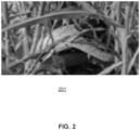
- the conventional practice typically involves trained agronomists manually going out into fields and measuring the stems using Vernier calipers (see e.g. FIG. 2 ). This technique is slow, inaccurate, hazard-prone, and highly labor intensive.
- Jin and Zakhor see [18A] Jihui Jin and Avideh Zakhor. Point cloud based approach to stem width extraction of sorghum.
- plant population plays a vital role in agricultural systems due to its strong influence on grain yield [1B]-[6B].
- grain yield per unit area follows a parabolic function of plant population [1B], [3B], [7B].
- optimal plant population that maximizes grain yield, where the optimal value depends on a number of environmental factors such as nitrogen, soil, and precipitation [8B]-[10B]. Therefore, accurate measurement of plant population can provide valuable information for estimating grain yield.
- sensors investigated include lidar [13B], [14B], Time-of-Flight (ToF) camera [15B], and laser pointers [16B], [17B].
- these sensors typically do not provide sufficient discrimination between corn and surrounding material, and hence are prone to large measurement errors. In particular, they cannot easily differentiate between corn leaves, debris, and weeds, which may trigger similar signal as corn stalks in the measurement. Hence the studies involving those sensors either were limited to weed free fields (which is impractical in production fields), or suffered major errors from weed interference.
- Monocular RGB cameras on the other hand, have the potential to identify corn stalks against complex background.
- Deep learning is a set of methods that allow end-to-end training and prediction. Deep learning models take raw data input and automatically learn the representations from the data's internal structure. Typically, a deep learning model consists of multiple modules each of which slightly increases the level of abstraction from the previous representation. When enough such modules are used, very intricate structures can be learned such that relevant patterns are recognized whereas irrelevant variations are suppressed. Deep learning has made tremendous progress in areas that have confounded traditional machine learning for many years including image recognition [20B], [22B].
- Deep learning methods have been shown capable of recognizing complex structures and features in the presence of heavy noise.
- Today, deep neural networks are approaching human level at image recognition on Internet data [19B]-[22B].
- Convolutional neural networks are a class of deep learning methods that process multidimensional array data.
- the structure of a typical ConvNet is comprised of multiple layers of neurons connected in a serial manner, and neurons in each layer are organized in feature maps.
- neurons in ConvNets are only connected to a local patch of their predecessors. These neurons perform a weighted sum (convolution) on the feature maps in the previous layer. The sum is then activated by a non-linear function before passing to the next layer. All neurons in a feature map share the same set of weights (filter), and different feature maps have different filters.
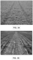
- FIG. 35 shows tire marks in a field that have led to permanent and direct damage due to heavy equipment passage.
- An equipment may also indirectly damage crop, for example, FIG. 36 shows soil compaction due to heavy equipment, which in this case has led to zero yield, but in others can significantly reduce yield.
- phenotyping is the measurement of plants including simple metrics such as emergence, stem-width, plant height; more sophisticated features such as total biomass, leaf angles, leaf area index; and complex properties such as hyper-spectral reflectance and fluorescence emission spectra. Phenotyping enables seed breeders and crop scientists to identify and select for genotypes that lead to desirable traits. The inability to collect phenotypic data in a low-cost and reliable manner can create a bottleneck in seed breeding progress. This critical gap can significantly hamper agricultural productivity by limiting the breeding of crops with greater yield potential, crops that can effectively resist abiotic stresses such as heat, drought, flooding etc., and precluding accurate yield prediction.
- Management of crop-systems includes activities such as pruning, culling, weeding, sampling, harvesting, spraying, seeding, thinning, and tilling.
- activities are either conducted manually which is labor intensive, or through devices that are pulled by tractors.
- Smart devices pulled by tractors that can identify and selectively spray chemicals onto undesirable plants in the agricultural systems are available.
- tractor pulled systems are impractical when crop canopy grows.
- these heavy systems cause soil compaction which is undesirable for yield.
- these systems can damage plants when they drive over them or brush against them.
- the ROWBOT system provides a robotic mechanism for applying Nitrogen.
- systems like the ROWBOT system can damage plants if they drive over them.
- Koselka et al. teach a robotic system for scouting and management in grapevine. However, the robot does not ensure that crop plants are not damaged during operation or if it drives over them.
- Agricultural crop products are heavily commoditized. In the absence of any major differentiators, farmers are hard pressed to compete on the prices of their products. Increasing agricultural productivity has created abundant supply of agricultural produce in certain geographies. Grains can be stored for long duration in grain silos. Vegetables and fruit can be rapidly transported from their place of production to a place of consumption at reasonable cost in many geographies. As a result, growers are under increasing price pressure. The profit margin of the grower is the net profit they can expect to earn after paying for seed, inputs (such as fertilizers, pesticides, insecticides, and other chemicals) and management costs, which includes cost of labor and equipment financing.
- inputs such as fertilizers, pesticides, insecticides, and other chemicals
- the increasing cost pressure makes it important for growers to have access to low-cost scouting mechanisms that can inform decisions on whether or not to apply input.
- the cost of a ground-based scouting mechanism includes its manufacturing cost, distribution cost, and operational cost.
- the manufacturing cost depends, among other things, on the material it is constructed with, the propulsion mechanism if it is self-propelled, the complexity of actuation mechanism for its turning and traversing the field, and the electronic components it may use. Heavier robots will typically be more expensive to maneuver, so will be complex robots requiring rack-and-pinion and other mechanisms to turn. Heavier robots are also typically difficult to transport, requiring higher transportation and distribution costs.
- Heavier robots are also typically expensive to operate, since they can easily damage plants if they run over them, they can also damage property or people if they collide with them, and they require more power to pull their weight, which leads to increased fuel/electricity costs. Heavier robots also typically compact soil and damage plants, which will lead to cost due to reduction in yield.
- a different class of scouting mechanism from ground robots is aerial robots.
- aerial robots There has been work in aerial scouting of agricultural fields for phenotyping and other agronomic functions to inform field management.
- Aerial scouting can be performed using unmanned aerial vehicles (e.g., drones), manned aircraft, or satellites.
- unmanned aerial vehicles e.g., drones
- manned aircraft e.g., manned aircraft
- satellites e.g., manned aircraft
- Each platform has unique advantages and disadvantages compared to each other.
- aerial scouting only reveals the stress symptoms that are visible from the top of the canopy. These may include change in color of leaves, overtly damaged plants, or areas of low growth.
- Aerial scouting may be conducted using RGB (visual) spectrum images, or images with multiple spectra that are not visible to the naked eye.
- Aerial scouting typically does not reveal under canopy characteristics, nor does it typically reveal minor defects and early indicators of stress on plants, especially when the plants are just emerging and not easily visible in aerial images. Furthermore, the state of the art aerial drones typically have very limited endurance, especially the multi-rotor type drones (which typically only have an endurance of 10-30 minutes), making it harder for them to cover in detail larger areas. Furthermore, these robots can be expensive to operate due to regulation, limited endurance, higher cost of manufacturing, and safety.
- Emerging aerial sensing methods include active radiation based sensors, including radars, lidars, and sonar sensors. However, in addition to typically prohibitive costs, these aerial sensors typically do not have sufficient resolution to reveal early indicators of stress. These aerial sensors typically have limited range, and as such can only be used on low-flying manned or unmanned aircraft, where weight, power, and sensor update-rate typically make it infeasible to use these sensors.
- the prevalent method for agricultural scouting is manual or "on foot" scouting, where a trained agronomist walks through the field.
- the agronomist may visually inspect plants, or take samples of plants or soil.
- Agronomists typically have at least a BS degree and many have higher degrees. This method is colloquially termed as boots-on-ground scouting.
- this method of scouting is labor intensive, and can be expensive due to the high costs associated with hiring and supporting agronomists.
- the Robotanist is an agricultural phenotyping robot developed by researchers at CMU in 2016. The robotanist is built over a metal frame and carries a number of sensors required for highly precise phenotyping. However, this robot weighs around 300 lbs. and can significantly damage crop-plants when it drives over them.
- U.S. Patent No. 8,381,501 issued February 26, 2013 describes an agricultural scouting robot for operation in grapevines. It appears that this robot does not ensure that crop plants are not damaged during operation or if it drives over them. Furthermore, it appears that the robot does not necessarily have the capability to turn around 180° in a row. In fact, it appears that no upper limits on size or weight specifications are provided.
- Husky is a larger rover from Clear Path, but with a width of 26.4 inches, it is difficult for it to travel comfortably in typical Maize (Corn) crop, and it cannot travel in typical Soybean rows.
- the Clear Path rovers do not typically come integrated with sensors and systems required for agricultural scouting tasks, such as automated stand-counting, stalk angle determination, stalk width estimation, or biomass estimation.
- Robotic rovers are available from Robotnik, Omron Adept technologies, and ROWBOT. More traditional low-clearance track based robots are also available from QinetiQ, Naio, Fendth, and iRobot. While many off-the-shelf options are available, these devices typically lack an integration of a suite of sensors, autonomy technologies, software, data recording capability, and sensor integration modularity for plant phenotyping, specifically plant phenotyping under the canopy.
- the ROWBOT system is designed to be insertable in rows of agricultural crops for applying fertilizer.
- the ROWBOT is heavy, driven by diesel engines, and can permanently damage crops if it drives over them. It appears that the system barely fits in rows of corn. Corn rows spacing can vary between 28-32 inches, and as mentioned previously, crop row-spacing can be much smaller, or non-existent in prevalent agricultural practices.
- the system also carries heavy fertilizer tanks. As such, it is not feasible to scout agricultural fields with this system without risking damage to plants.
- the ROWBOT cannot turn around 180° in a row.
- the system utilizes contact sensors to find crop row edges and stay in the middle of rows. However, these types of sensors will not work when the crop-plants are very small.
- the sensors used according to an example are low-cost, consisting of a side-facing monocular RGB camera (ELPUSBFHD01M,USA), a 2D LIDAR (2-D Hokuyo UTM-30LX), and wheel encoders for estimating robot velocity.
- the sensors are mounted on a small (e.g., ⁇ 15 lb) phenotyping robot (sometimes referred to herein as TerraSentia) that can traverse through crop rows in an agricultural field using the LIDAR.
- an image processing algorithm designed to extract the foreground in the presence of significant leaf and stem clutter, view of other rows, and varying lighting.
- the extraction can be based upon data from a side-facing USB camera on a moving robot.
- an algorithm provided herein uses the ratio between estimated robot velocity from wheel encoders and pixel velocity from dense optical flow to estimate depth using a structure from motion (SfM) approach (with respect to the wheel encoders, it is noted that GPS does not work well under crop canopy due to multi-path and attenuation errors, hence, encoder velocity is an acceptable estimate of robot speed, especially at slow speeds when the wheels do not slip excessively).
- SfM structure from motion
- the SfM is adapted as described herein for phenotyping in cluttered and unstructured field conditions.
- Algorithms As described herein is a validation of various techniques in biomass sorghum fields. Algorithms according to various embodiments have been compared against available manually measured plots in an 80 Acre best-practices field trial at a leading University. A trained agronomist used industry-standard practices to measure the average stem-width of 18 plots. Various algorithms provided herein match the agronomist measurements within the allowable range of error set by an oversight agency (8%). The width estimation match was found to be 92.5% (using only vision) and 98.2% (using vision and LIDAR), where the total processing time for running both algorithms is 0.04 secs per video frame.
- the foreground extraction and robot-to-row depth techniques described herein can be utilized for automating other phenotypic measurements.
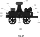
- a robot that is used for data acquisition is a lightweight(e.g., ⁇ 15 lb), ultra-compact, 3D printed, autonomous field phenotyping robot (sometimes referred to herein as TerraSentia).
- TerraSentia autonomous field phenotyping robot
- the lightness and thoughtful construction of the wheels help prevent permanent damage to any plant parts, even if the robot runs over them accidentally.
- the compactness allows the robot to easily traverse between narrow crop rows, especially in corn, hemp, and sorghum, where 30" or greater row spacing is common.
- Each wheel of the robot is powered by a separate motor with encoders and averaged encoder values provide a reasonable estimate of the robot speed.
- the robot travelled in various examples at a speed of about 1.3 feet per second (0.4 m/s). At this speed, the robot covers a row of a single 3m by 3m plot of a crop variety in under 10 seconds, and can cover several plots in a reasonable amount of time. Furthermore, at this speed, motion blur was not found to be significant on the camera (ELPUSBFHD01M, USA) used on the robot. Higher frame rate cameras could enable increasing speed of the robot.
- a Camera and Light Source As the robot traverses through crop rows, video data is acquired at 90 frames per second with a frame resolution of 640 x 480 pixels by the robot's camera.
- the acquisition is performed, in this example, with a low-cost digital monocular RGB camera (ELPUSBFHD01M, USA) mounted on the side of the robot chassis.
- the camera in this example, has a field view of 60°.
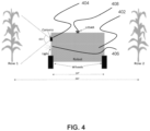
- a common inexpensive LED light source having a 3000K color temperature and providing 60 lumens of light, is attached on the robot chassis near the camera position to ensure ample brightness under the dark sorghum canopy. This is done to prevent the camera firmware from increasing the exposure time which could cause excessive motion blur.
- there was no control over the camera firmware The placements of the camera and light are shown in FIG. 4 .
- FIG. 5 shows an aerial view of 80 acres sorghum field (Maxwell Field, Savoy, IL, USA), consisting of 960 sorghum plots of different genotypes of Sorghum. All experiments on sorghum discussed herein have been performed on the 80 Acre Maxwells Field, Savoy, Illinois, during August to November, 2017. The field consists of 960 Sorghum plots of size 3m ⁇ 3m and 30 inch row spacing. The aerial image of FIG. 5 shows the marked height difference due to the different genotypes in each plot.
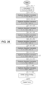
- Phase 1 (see those elements above the line marked "Phase 1" in FIG. 6 ) is the same for both algorithms, and involves a common image processing algorithm for foreground extraction (see the pseudo-code of Algorithm 1A provided below).
- Phase 2 (see those elements below the line marked "Phase 1" and above the line marked “Phase 2” in FIG. 6 ) consists of depth estimation using structure from motion and LIDAR point clouds for each approach, respectively (the final outputs from "Phase 2" are not separately identified as a "Phase”).
- the framework has been summarized in FIG. 6 and described in detail below.
- a fixed sized window is defined at the side (in this example, at the left side) of each video frame and only that region is processed to extract a stem boundary if present.
- the choice of this size is based on two assumptions valid for most crop fields: (1) The stem width does not exceed 4 inches; (2) Stems never come closer than 3 inches to the camera lens without blur.
- This window size has worked for validation tests, and hence it is possible to avoid using a variable-sized window - this avoids unnecessary and redundant calculations (in another example, a variable-sized window could be used; in another example, the window can extend the full height of the frame).
- Placement of the window is on a side (in this example) instead of the center because video frames sometimes blur towards the center (e.g., due to small row spacing), in spite of the high frame rate (e.g., 90 fps) and additional lights (see, e.g., the light on the robot of FIG. 4 ).
- the window has been placed at the left side, but choosing the right side is also acceptable.
- the placement of the window 702 of this embodiment is shown in FIG. 7 .
- the window 702 placed in each frame of the raw video is processed to find out if an un-occluded part of the stem is visible.
- the rest of the video frame does not need to be utilized, and this is done (in this example) to reduce computational overhead.
- discarding the rest of the frame does not cause any valuable information loss since the robot traverses through the entire row visiting each plant one by one, so all parts of the frame pass through the chosen window at some point in time.
- an approach of multiple windows is avoided to reduce the chance of double counting of the same plant multiple times (which would distort the estimated width distribution across the plot).
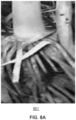
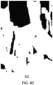
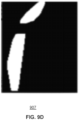
- FIGS. 8A-8F depict sequential steps of an embodiment for foreground extraction from a cropped window of a current video frame (see pseudo-code of Algorithm 1A provided below).
- these sequential steps include: FIG. 8A - Unprocessed window f n with high clutter; FIG. 8B - Edges of the image of FIG. 8A after Canny edge detection; FIG. 8C - Dilation of the image of FIG. 8B ; FIG. 8D - Erosion of the image of FIG. 8C ; FIG. 8E - Inversion of the image of FIG. 8D ; FIG. 8F - Foreground extraction and smoothing by removing unwanted components from the image of FIG. 8E after CCL (connected component labeling) and convex hull approximation respectively.
- CCL connected component labeling
- the pseudo-code of Algorithm 1A can provide for foreground extraction of cropped video frame from cluttered background as follows:
- FIGS. 8A-8F (and Algorithm 1A):
- SfM Structure from motion
- the SfM problem in computer vision is the problem of recovering the three-dimensional structure of a stationary scene from a set of projective measurements, represented as a collection of two-dimensional images, via estimation of motion of the camera.
- SfM typically involves the three main steps of: (1) extraction of features in images and matching these features between images; (2) camera motion estimation (e.g., using relative pairwise camera positions estimated from the extracted features); and (3) recovery of the 3D structure using the estimated motion and features (e.g., by minimizing the so-called re-projection error) (see, e.g., [26A] Onur O ⁇ zyesil, Vladislav Voroninski, Ronen Basri, and Amit Singer. A survey on structure from motion. CoRR, abs/1701.08493, 2017. URL http://arxiv.org/abs/1701. 08493 ). Steps (1) and (2) mentioned above are used in an embodiment to determine average pixel velocity of the clean foreground in each frame.
- This algorithm (see the pseudo-code of Algorithm 2A below) computes the dense optical flow for all points in the window and gives a 2 channel array with optical flow vectors ( Vx, Vy ).
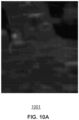
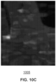
- 10A-10D show the gray-scale visualization of dense optical flow using Farnebffen algorithm in the direction of robot movement (according to an embodiment) for 5 consecutive windows.
- Lighter color means higher velocity (see Algorithm 2A (shown as pseudo-code) provided below).
- An approach of dense optical is adopted instead of sparse optical flow, that involve tracking of feature points across video frames (like Lucas Kanade algorithm (see, e.g., [20A] Bruce D. Lucas and Takeo Kanade. An iterative image registration technique with an application to stereo vision.
- Lucas Kanade algorithm like, e.g., [20A] Bruce D. Lucas and Takeo Kanade.
- FIG. 4 shows the LIDAR sensor mounted on the robot in one possible location.
- the LIDAR is a type of active range sensor that uses a scanning mechanism to provide distance of objects in its range.
- the returns from the LIDAR are known as the point cloud.
- LIDAR sensor range can be in excess of 30m, meaningful readings do not surpass a few meters, because row spacing is (in this example) below 1m. Frequent occlusion by leaves and weeds interfere with measurements from ahead of the lane, hence, the points too close to the robot are discarded as clutter by leaves.
- the LIDAR point cloud can be used to estimate distance to the row using the points by a weighted mean of the point distances to the line of traversal of the robot.
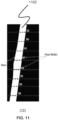
- Phase 2 a discussion will be directed to Width Estimation from SFM and LIDAR data as follows: A clean white foreground mask on black background, which has the same length and breadth as the fixed window, is obtained after Phase 1, which is the mask for the desired stem boundary. N imaginary horizontal lines are drawn on the mask image and for each line, the number of white pixels are recorded. This gives the width in pixels ( W P i ) at N different locations of the stem (as shown in FIG. 11 ). The actual width estimation process from pixel width is described in more detail as follows (see, also, the pseudo-code of Algorithm 3A below).
- the Width Estimation from SFM approach can operate as follows: To obtain the actual stem width W Si , each W Pi has to be multiplied with a certain ratio R. The ratio of the average horizontal foreground pixel velocity (Vx) calculated as described above (see Camera Motion Estimation ), to the actual instantaneous velocity ( V R ) of the robot gives R, which is the desired ratio ( V R is obtained from the encoder readings). Equations 1A, 2A and 3A below show the steps for width calculation from SfM. The width (Ws) obtained for a particular window is the average of all the W Si.
- the Width Estimation from LIDAR data approach can operate as follows: The instantaneous distance from the camera to the crop row under consideration (D) is obtained as described above (see, Lateral Distance Estimation Using LIDAR or other range sensors ). The width from LIDAR W L is calculated according to Equations 4A and 5A.
- Ws and W L are the outputs from two algorithmic approaches presented. The results obtained after validating these estimations are discussed in detail below.
- the x-axis represents "Plant Count”
- the y-axis represents "Width (inches)”
- the "A” bars one of which is labeled
- the "B” bars one of which is labeled
- the "C” bars one of which is labeled
- the standard deviation of such a distribution is 0.256 inches, clearly showing that averaging only 3 measurements per plot (such as discussed above, which is the conventional practice), is not very accurate. Even these latter measurements do not represent the "ground truth", however, they are the best available set of data against which a comparison could be made.
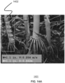
- FIG. 14A shows a processed video frame for plot 17MW0159 as the robot according to an embodiment traversed through the plot.
- the processing window 1502 after cropping the video frame is marked indicated as the vertical rectangle on the left-hand side.
- the dark and light colors of various numbers indicate width using structure from motion and LIDAR data respectively.
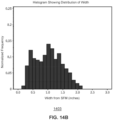
- FIGS. 14B and 14C show the distribution of width for algorithms presented herein (using SFM and LIDAR, respectively) and FIG. 14D shows hand measured ground truth. Table I(A) (below) shows mean and variance of such measurements.
- FIG. 15A this depicts a typical video frame with window 1502 (rectangular marker).
- This FIG. 15A shows W Si (the 1 st , 3 rd , 5 th , 7 th , 9 th , and 11 th numbers from the top down) and W Li (the 2 nd , 4 th , 6 th , 8 th , 10 th , and 12 th numbers from the top down) noted inside window 1502.
- Ws second number from the bottom on the left
- W L number at the bottom on the left
- This FIG. 15A also shows V as the instantaneous robot velocity.
- This FIG. 15A also shows V as the instantaneous robot velocity.
- FIG. 15A also shows D as the robot to plant distance measured by LIDAR.
- FIG. 15A shows distribution of width from SfM across all video frames (x-axis: width in inches; y-axis: normalized frequency).
- FIG. 15C shows distribution of width from LIDAR across all frames in the video (x-axis: width in inches; y-axis: normalized frequency).
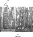
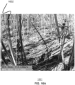
- FIG. 16A this depicts a typical video frame with window 1602 (rectangular marker)
- This FIG. 16A shows WSi (the 1 st , 3 rd , 5 th , 7 th , 9 th , and 11 th numbers from the top down) and W Li (the 2 nd , 4 th , 6 th , 8 th , 10 th , and 12 th numbers from the top down) noted inside window 1602.
- Ws second number from the bottom on the left
- W L number at the bottom on the left
- This FIG. 16A also shows V as the instantaneous robot velocity.
- FIG. 16A also shows D as the robot to plant distance measured by LIDAR.
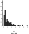
- FIG. 16B shows distribution of width from SfM across all frames in the video (x-axis: width in inches; y-axis: normalized frequency).
- FIG. 16C shows distribution of width from LIDAR across all frames in the video (x-axis: width in inches; y-axis: normalized frequency).
- ground robots typically need to deal with harsher conditions than faced by a UAS (however, ground robots can be more desirable for high throughput phenotyping (as opposed to a UAS), since such ground robots typically have a far closer and more detailed under-canopy view of plants) [25A].
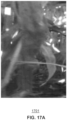
- FIG. 17A shows a situation where even manual classification of the image for stem or leaf is difficult.
- the picture shows a leaf, having color, size, eccentricity, orientation and shape just like the stem. Hence the algorithm falsely detects this as a stem.
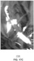
- FIG. 17B shows a stem almost completely occluded by a leaf in front; there is no way to detect the stem in this case with the sensors that have been used in the described embodiments.
- FIG. 17B shows bright sunlight entering through dense sorghum canopy, causing stems and leaves to be only partially illuminated. In this case, only the partial contour is taken into account, leading to faulty width estimation.
- Stem width is an important phenotype needed by breeders and plant-biologists to measure plant growth, however, its manual measurement is typically cumbersome, in-accurate, and inefficient.
- Various algorithms presented herein use a common image processing core that is designed to extract the foreground in the presence of significant leaf and stem clutter, view of other rows, and varying lighting, from a side-facing USB camera on a small mobile robot. Using the extracted foreground, one algorithmic approach described herein uses estimates of robot velocity from wheel encoders and structure from motion to estimate depth, while another approach described herein employs use of the LIDAR 2-D point cloud to estimate the depth.
- various embodiments utilize a structure from motion algorithm that does not need a depth sensor.
- various embodiments provide a general and computationally light algorithm for autonomous width estimation of crops with cylindrical stems under highly uncertain field conditions.
- various embodiments provide enhancements in the field of robotics for phenotyping applications.
- various embodiments provide algorithms for filtering useful content from noisy robot-obtained field images.
- various embodiments can facilitate generation of datasets that could feed future machine learning pipelines.
- various algorithmic approaches described herein can be used to develop a dataset specifically for field conditions (e.g., with masked labels for stems and leaves). This would enable the use of machine learning in the context of phenotype estimation tasks directed to, for example, leaf area, leaf angle, leaf count and further improved stem width.
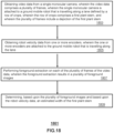
- step 1803 comprises obtaining video data from a single monocular camera, wherein the video data comprises a plurality of frames, wherein the single monocular camera is attached to a ground mobile robot that is travelling along a lane defined by a row of crops, wherein the row of crops comprises a first plant stem, and wherein the plurality of frames include a depiction of the first plant stem.
- step 1805 comprises obtaining robot velocity data from a plurality of encoders, wherein the encoders are attached to the ground mobile robot that is travelling along the lane.
- step 1807 comprises performing foreground extraction on each of the plurality of frames of the video data, wherein the foreground extraction results in a plurality of foreground images.
- step 1809 comprises determining, based upon the plurality of foreground images and based upon the robot velocity data, an estimated width of the first plant stem.
- step 1903 comprises obtaining video data from a camera, wherein the video data comprises a plurality of frames, wherein the camera is attached to a ground mobile robot that is travelling along a lane defined by a row of crops, wherein the row of crops comprises a first plant stem, and wherein the plurality of frames include a depiction of the first plant stem.
- step 1905 comprises performing foreground extraction on each of the plurality of frames of the video data, wherein the foreground extraction results in a plurality of foreground images.
- step 1907 comprises obtaining sensor data from a light detection and ranging (LiDAR) sensor, wherein the LiDAR sensor is attached to the ground mobile robot that is travelling along the lane defined by the row of crops, and wherein the sensor data includes at least a portion of the row of crops.
- step 1909 comprises determining, based upon the plurality of foreground images and based upon the sensor data, an estimated width of the first plant stem.
- LiDAR light detection and ranging
- step 2003 comprises obtaining video data from a single monocular camera, wherein the video data comprises a plurality of frames, and wherein the plurality of frames includes a depiction of a first plant stem in a row of crops.
- step 2005 comprises obtaining vehicle velocity data from at least one of a plurality of wheels of a mobile vehicle.
- step 2007 comprises performing foreground extraction on each of the plurality of frames of the video data, wherein the foreground extraction results in a plurality of foreground images.
- step 2009 comprises determining, based upon the plurality of foreground images and based upon the vehicle velocity data, an estimated width of the first plant stem.
- a device comprising: a processing system including a processor; and a memory that stores executable instructions that, when executed by the processing system, perform operations, the operations comprising: obtaining video data from a single monocular camera, wherein the video data comprises a plurality of frames, wherein the single monocular camera is attached to a ground mobile robot that is travelling along a lane defined by a row of crops, wherein the row of crops comprises a first plant stem, and wherein the plurality of frames include a depiction of the first plant stem; obtaining robot velocity data from a plurality of encoders, wherein the encoders are attached to the ground mobile robot that is travelling along the lane; performing foreground extraction on each of the plurality of frames of the video data, wherein the foreground extraction results in a plurality of foreground images; and determining, based upon the plurality of foreground images and based upon the robot velocity data, an estimated width of the first plant stem.
- the foreground extraction comprises processing, for each of the plurality of frames of the video data, only a fixed sized window that is smaller than each of the plurality of frames.
- the fixed sized window associated with each of the plurality of frames is located off-center in each of the plurality of frames.
- the foreground extraction comprises, for each of the plurality of frames of the video data: a first function to perform edge detection; a second function to perform morphing; and a third function to perform connected component labeling.
- the first value is the estimated width of the first plant stem.
- the first width is determined as a horizontal width.
- the determining the estimated width of the first plant stem further comprises: determining a second width, in pixels, at a second location of the first plant stem as depicted in the first one of the plurality of frames of the video data; multiplying R times the second width, resulting in a second value; and averaging the first value and the second value, resulting in the estimated width of the first plant stem.
- the ground mobile robot comprises at least one wheel
- the one or more encoders determines the robot velocity data via detection of a rotation of the at least one wheel.
- the operations further comprise: obtaining additional video data from the single monocular camera, wherein the additional video data comprises an additional plurality of frames, wherein the row of crops comprises a second plant stem, and wherein the additional plurality of frames include another depiction of the second plant stem; obtaining additional robot velocity data from the one or more encoders; performing additional foreground extraction on each of the additional plurality of frames of the additional video data, wherein the additional foreground extraction results in an additional plurality of foreground images; and determining, based upon the additional plurality of foreground images and based upon the additional robot velocity data, an additional estimated width of the second plant stem.
- a non-transitory computer-readable storage medium comprising executable instructions that, when executed by a processing system including a processor, perform operations, the operations comprising: obtaining video data from a camera, wherein the video data comprises a plurality of frames, wherein the camera is attached to a ground mobile robot that is travelling along a lane defined by a row of crops, wherein the row of crops comprises a first plant stem, and wherein the plurality of frames include a depiction of the first plant stem; performing foreground extraction on each of the plurality of frames of the video data, wherein the foreground extraction results in a plurality of foreground images; obtaining sensor data from a light detection and ranging (LiDAR) sensor, wherein the LiDAR sensor is attached to the ground mobile robot that is travelling along the lane defined by the row of crops, and wherein the sensor data includes at least a portion of the row of crops; and determining, based upon the plurality of foreground images and based upon
- the foreground extraction comprises, for each of the plurality of frames of the video data: a first function to perform edge detection; a second function to perform morphing; and a third function to perform connected component labeling.
- the determining the estimated width of the first plant stem comprises: determining, based upon the sensor data, an estimated distance D from the camera to the first plant stem; determining a first width, in pixels, at a first location of the first plant stem as depicted in a first one of the plurality of frames of the video data; and multiplying the first width times D divided by a focal length of a lens of the camera, resulting in a first value.
- the first value is the estimated width of the first plant stem.
- the camera is a single monocular camera.
- the operations further comprise: obtaining additional video data from the camera, wherein the additional video data comprises an additional plurality of frames, wherein the row of crops comprises a second plant stem, and wherein the additional plurality of frames include another depiction of the second plant stem; performing additional foreground extraction on each of the additional plurality of frames of the additional video data, wherein the additional foreground extraction results in an additional plurality of foreground images; obtaining additional sensor data from the LiDAR sensor, wherein the additional data includes at least an additional portion of the row of crops; and determining, based upon the additional plurality of foreground images and based upon the additional sensor data, an additional estimated width of the second plant stem.
- the LiDAR sensor comprises a 2-D LiDAR sensor.
- a mobile vehicle comprising: a body; a single monocular camera attached to the body; a plurality of wheels attached to the body; a processing system including a processor; and a memory that stores executable instructions that, when executed by the processing system, perform operations, the operations comprising: obtaining video data from the single monocular camera, wherein the video data comprises a plurality of frames, and wherein the plurality of frames includes a depiction of a first plant stem in a row of crops; obtaining vehicle velocity data from at least one of the wheels; performing foreground extraction on each of the plurality of frames of the video data, wherein the foreground extraction results in a plurality of foreground images; and determining, based upon the plurality of foreground images and based upon the vehicle velocity data, an estimated width of the first plant stem.
- the mobile vehicle is an autonomous ground mobile robot and the operations are performed without use of global positioning system (GPS) data
- the mobile vehicle further comprises at least one encoder, wherein the at least one encoder obtains the vehicle velocity data, and wherein the single monocular camera is located in the body, on the body or any combination thereof.
- the mobile vehicle can comprise an airborne vehicle (e.g., drone, airplane, helicopter, or the like).
- an airborne vehicle can travel, for example, below the crop canopy.
- Other suitable modifications can be applied to the subject disclosure. Accordingly, the reader is directed to the claims for a fuller understanding of the breadth and scope of the subject disclosure.
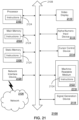
- FIG. 21 epicts an exemplary diagrammatic representation of a machine in the form of a computer system 2100 within which a set of instructions, when executed, may cause the machine to perform any one or more of the methods discussed herein.
- the machine may be connected (e.g., using a network) to other machines.
- the machine may operate in the capacity of a server or a client user machine in server-client user network environment, or as a peer machine in a peer-to-peer (or distributed) network environment.
- the machine may comprise a server computer, a client user computer, a personal computer (PC), a tablet PC, a smart phone, a laptop computer, a desktop computer, a control system, a network router, switch or bridge, or any machine capable of executing a set of instructions (sequential or otherwise) that specify actions to be taken by that machine.
- a communication device of the subject disclosure includes broadly any electronic device that provides voice, video or data communication.
- the term "machine” shall also be taken to include any collection of machines that individually or jointly execute a set (or multiple sets) of instructions to perform any one or more of the methods discussed herein.
- the computer system 2100 may include a processor 2102 (e.g., a central processing unit (CPU), a graphics processing unit (GPU, or both), a main memory 2104 and a static memory 2106, which communicate with each other via a bus 2108.
- the computer system 2100 may further include a video display unit 2110 (e.g., a liquid crystal display (LCD), a flat panel, or a solid state display.
- the computer system 2100 may include an input device 2112 (e.g., a keyboard), a cursor control device 2114 (e.g., a mouse), a disk drive unit 2116, a signal generation device 2118 (e.g., a speaker or remote control) and a network interface device 2120.
- the disk drive unit 2116 may include a tangible computer-readable storage medium 2122 on which is stored one or more sets of instructions (e.g., software 2124) embodying any one or more of the methods or functions described herein, including those methods illustrated above.
- the instructions 2124 may also reside, completely or at least partially, within the main memory 2104, the static memory 2106, and/or within the processor 2102 during execution thereof by the computer system 2100.
- the main memory 2104 and the processor 2102 also may constitute tangible computer-readable storage media.
- Dedicated hardware implementations including, but not limited to, application specific integrated circuits, programmable logic arrays and other hardware devices can likewise be constructed to implement the methods described herein.
- Applications that may include the apparatus and systems of various embodiments broadly include a variety of electronic and computer systems. Some embodiments implement functions in two or more specific interconnected hardware modules or devices with related control and data signals communicated between and through the modules, or as portions of an application-specific integrated circuit.
- the example system is applicable to software, firmware, and hardware implementations.
- the methods described herein are intended for operation as software programs running on a computer processor.
- software implementations can include, but not limited to, distributed processing or component/object distributed processing, parallel processing, or virtual machine processing can also be constructed to implement the methods described herein.
- tangible computer-readable storage medium 2122 is shown in an example embodiment to be a single medium, the term “tangible computer-readable storage medium” should be taken to include a single medium or multiple media (e.g., a centralized or distributed database, and/or associated caches and servers) that store the one or more sets of instructions.
- tangible computer-readable storage medium shall also be taken to include any non-transitory medium that is capable of storing or encoding a set of instructions for execution by the machine and that cause the machine to perform any one or more of the methods of the subject disclosure.
- tangible computer-readable storage medium shall accordingly be taken to include, but not be limited to: solid-state memories such as a memory card or other package that houses one or more read-only (non-volatile) memories, random access memories, or other re-writable (volatile) memories, a magneto-optical or optical medium such as a disk or tape, or other tangible media which can be used to store information. Accordingly, the disclosure is considered to include any one or more of a tangible computer-readable storage medium, as listed herein and including art-recognized equivalents and successor media, in which the software implementations herein are stored.
- Each of the standards for Internet and other packet switched network transmission (e.g., TCP/IP, UDP/IP, HTML, HTTP) represent examples of the state of the art. Such standards are from time-to-time superseded by faster or more efficient equivalents having essentially the same functions.
- Wireless standards for device detection e.g., RFID
- short-range communications e.g., Bluetooth, WiFi, Zigbee
- long-range communications e.g., WiMAX, GSM, CDMA
- a support vector machine (SVM) classifier is trained to classify the features extracted from a convolutional neural network with pre-trained weights.
- SVM support vector machine
- the result is a robust stand-counting algorithm (according to an embodiment) where the only sensor needed is a low-cost ( ⁇ $30) RGB camera.
- Extensive field trials show that the detection is robust against noises such as corn leaves, weeds, varying lighting conditions, and residues from the previous year.
- the disclosed system of an embodiment achieves high accuracy and reliability throughout the growing season. In essence, the disclosed system of an embodiment enables real-time robotic phenotyping in breeding plots and production fields. Robotic phenotyping is a welcome contribution, since it can help to overcome the phenotyping bottleneck [23B], [24B] that has slowed progress in breeding better crops.
- the platform used in this study is a four-wheel unmanned vehicle.
- the robot is (in this example) 12 in tall ⁇ 20 in long ⁇ 14 in wide, with a 6 in ground clearance, and weighs 14.5 lbs.
- the system may use a robot having any dimensions which allow the robot to traverse between crop rows.
- Such a compact and lightweight design allows the robot to easily traverse between crop rows of typical row spacing for corn.
- the robot is powered (in this example) by four Lithium Ion batteries that offer up to 4 h duration.
- the robot may alternatively use power sources including but not limited to battery types other than lithium ion and solar power.
- Images are recoded (in this example) with an RGB digital camera (ELP USBFHD01M, USA) mounted on the side of the robot chassis, but other cameras may be used, whether in visual or other spectra.
- the field of view of the camera (in this example) is 60°. In other embodiments the field of view of the camera may be between 10° and 360°.
- the number of corn plants captured in the image depends on the distance between the camera and plant row, as well as the spacing between adjacent plants. In a 30-in row, for instance, two to three corn plants normally appear in the image.
- the camera points down at an angle (in this example) of 35° to avoid observing corn rows far away. In other embodiments the camera points down at an angle between 0° and 85°.
- the resolution of the camera is 640 ⁇ 480, and it records at 30 frames per second. In other embodiments, the resolution of the camera is at least 240P, and it records at least 5 frames per second.
- the camera has a USB2 interface (although other interfaces will also work) that connects to a Jetson TX2 (NVIDIA, USA) or other computer(s), an embedded module for fast and efficient deep neural network inference. In another embodiment any module capable of efficient deep neural network inference may be used.
- the module houses 8GB memory that is shared between a CPU and GPU, and is able to process image frames captured by the camera in real-time. In other embodiments, the module houses between 1GB and 1024GB of memory.
- Images captured in outdoor environment are subject to a wide range of variations such as sunlight, occlusion, and camera view angle, etc. Additionally, corn plants go through significant changes during the growing season. Such variations make it difficult for classification using conventional approaches. Therefore, in the current disclosure a deep learning model is trained by combining a convolutional neural network and a support vector machine to classify the presence or absence of corn.
- Deep learning can identify corn plants in an image. However, this is not enough to count plants from a moving robot since it is difficult to distinguish different corn plants to avoid double-counting.
- One way to address this is to draw a fixed Region of Interest (ROI) in the image whose width is on average smaller than the gap between neighboring corn plants.
- the deep learning algorithm is applied only to the pixels within the ROI to detect whether or not a plant is present. This leads to a binary signal that takes (for example) the value 1 for all frames in which a corn stalk is detected in the ROI, and a value -1 otherwise (including weeds, leaves, or other green matter).
- the ROI is placed (in one embodiment) in the center of the image, but this is not necessary.
- the Mobilenet architecture contains a standard convolution layer followed by 13 depthwise separable convolution layers.
- the model takes 224 ⁇ 224 RGB images as input and outputs 1024-dimensional feature vectors.
- the fully connected and softmax layer in the original model are replaced by SVM for classification. Details of the architecture (which can be utilized by various embodiments) are shown in FIG. 25 . It is noted that even for such a compact architecture, it still takes an enormous amount of data to train the model as it contains 4.2 million parameters. However, there does not exist such a dataset specifically for agriculture. To alleviate the steep requirement on training data, the present disclosure utilizes (in various embodiments) the principles of transfer learning.
- the model is fine-tuned based on the pre-trained weights on the ILSVRC dataset [34B].
- a Support Vector Machine is a widely used model for classification [35B]-[40B]. It follows a linear model that constructs a hyperplane as shown in Equation (1B).
- the optimal hyperplane maximizes the margin, which is defined to be the smallest distance between the decision boundary and any of the samples. Given a set of data, where x i ⁇ R n and t i ⁇ ⁇ -1,1 ⁇ , the distance of a point x i to the decision boundary is given by Equation (2B). Thus the maximum margin solution can be found by solving Equation (3B). If w and b are further scaled such that the closest point from either class to the hyperplane is ⁇ 1, the optimization is then equivalent to a quadratic programming problem (Equation (4B)).
- Images are captured (in these embodiments) by the side facing camera on the robot throughout the growing season. The camera points slightly downward so that only the closest row is visible. Patches are cropped from the images and labeled according to the presence or absence of corn as positive and negative samples, respectively.
- the number of training and testing samples (of a particular example) are listed in Table IB. Data augmentation was also employed to further increase the training data. Images (in this example) are rotated ( ⁇ 10°), zoomed (88% to 112%), vertically shifted ( ⁇ 15%), and horizontally flipped. Each image is augmented (in this example) by 16-fold via randomly drawing transformations from the list.
- the weights for the MobileNet are kept constant during fine-tuning.
- the hyper-parameters for SVM are determined by grid search and cross validation implemented in a Python package: scikit-learn [44B]. Linear kernel and radial basis function (RBF) kernel are investigated. Table IIB lists the values of hyper-parameters that are considered in this example. All combinations are exhausted to identify the optimal parameters.
- the ROI width is chosen so that only one corn plant appears in it, exceptions to this assumption arise due to variations in plant spacing. If the gap between two neighboring plants is smaller than the ROI width, the detection signal of these two corn plants will merge into a single plateau (see FIGS. 26A and 26B ). Therefore it will likely underestimate the population to take the number of plateaus as the count. These errors can build up, degrading the estimation performance.
- the rigid transformation between two consecutive frames I 1 and I 2 is computed when a positive signal of the binary classification is present.
- a rigid transformation is a combination of rotation, translation, and reflection.
- Equation (6B) a rigid transformation in R 2 is given in Equation (6B). Two pairs of points are needed to solve for the transformation matrix M.
- the system of these embodiments extracts and matches about 100 SURF [45B] feature points in both images and solves for the least-square solution for M 2. Since the motion of the camera is predominantly in X-direction, the system of these embodiments sums up the values of t x from the first frame in the plateau till the last to be T. If the ROI finishes scanning through a corn before encountering the next one as in most cases, T is approximately equal to ROI width w.
- the hyper-parameters are almost the same for the three growth stages except that the C-value is different for V4, largely due to the difference in appearance of corn plants at V4 from VT and R2.
- the radial basis function kernel consistently works better than the linear kernel, and the optimal ⁇ -value for the kernel is identical at three stages. The results indicate that the features from corn images at different stages are comparable and it is possible to classify all images using a single unified classifier.
- the performance metrics are also consistently high for three growth stages. It is noted the training samples exclude leaves and only focus on stems and stalks. The metrics demonstrate that the deep learning model is capable of distinguishing subtle difference in images and thus reduces the inference of leaves and weeds. The mean accuracy for all stages is 92.97%. In addition, predictions are averaged by their k neighbors (k is an odd integer). Assuming a corn stalk is present in image frames I i , ...
- step 3005 comprises capturing, by a camera coupled with a processing system that includes a processor, a group of images associated with a field of plants, wherein the group of images is captured while the camera is in motion in the field.
- step 3010 comprises applying, by the processing system, a convolutional neural network to the group of images to extract feature vectors.
- step 3015 comprises applying, by the processing system, a support vector machine to the feature vectors to classify the feature vectors resulting in classified features.
- step 3020 comprises applying, by the processing system, motion estimation based on a rigid transformation to the classified features resulting in corrected count data.
- step 3025 comprises determining, by the processing system, a plant population for the field of plants based on the classified features and the corrected count data.
- the support vector machine comprises a soft margin support vector machine that applies a slack variable to data points on or inside of a correct decision boundary.
- the group of images are not an aerial view of the field of plants, and a view of the camera is at a downward angle.
- the motion of the camera while the group of images is being captured is at a constant velocity.
- the convolutional neural network is applied only to a fixed region of interest in each image of the group of images.
- the convolutional neural network comprises a standard convolution layer followed by multiple depthwise separable convolution layers.
- data augmentation is applied to training data for the convolutional neural network.
- the data augmentation in this embodiment is based on image rotation, image zooming, image vertical shifting, image horizontal flipping, or a combination thereof.
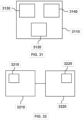
- FIG. 31 shows a block diagram representing an embodiment of an apparatus for determining a plant population for a field of plants.
- the apparatus comprises an unmanned vehicle 3110, a battery 3120, a processing system 3130, and a camera 3140.
- the processing system 3130 includes a processor.
- the battery 3120, the processing system 3130, and the camera 3140 are supported by the unmanned vehicle 3110.
- the unmanned vehicle 3110, the processing system 3130, and the camera 3140 are electronically coupled to the battery 3120.
- the camera 3140 is in electronic communication with the processing system 3130.
- the battery 3120 supplies electricity to the unmanned vehicle 3110, the processing system 3130 and the camera 3140.
- the camera 3140 captures a group of images associated with a field of plants while the unmanned vehicle 3110 travels along rows of the field.
- the group of plant images captured by the camera 3140 are electronically communicated to the processing system 3130.
- the processing system 3130 implements a convolutional neural network, a support vector machine, and motion estimation with respect to the group of images to determine a plant population for the field of plants.
- the camera 3140 is pointed at a downward angle.
- the support vector machine comprises a soft margin support vector machine that applies a slack variable to data points on or inside a correct decision boundary.
- the unmanned vehicle 3110 travels along the rows of the field at a constant velocity.
- the convolutional neural network is applied only to a fixed region of interest in each image of the group of images.
- the convolutional neural network comprises a standard convolution layer followed by multiple depthwise separable convolution layers.
- data augmentation is applied to training data for the convolutional neural network, and the data augmentation is based on image rotation, image zooming, image vertical shifting, image horizontal flipping, or a combination thereof.
- the camera 3140 mounted on the unmanned vehicle 3110 is on a gimbal or servo that automatically adjusts the view of the camera based on features of the images collected by the camera 3140.
- an air jet that is, a mechanism for producing a flow of air
- the air jet clears obstructions such as leaves from the frame of the camera 3140 so unobstructed images of the plants can be captured by the camera 3140.
- FIG. 32 shows a block diagram representing an embodiment of an apparatus for computing a plant population.
- the apparatus comprises a non-transitory machine-readable storage medium 3210, executable instructions 3215, a processing system 3220, and a processor 3225.
- the non-transitory machine-readable storage medium 3210 is in electronic communication with the processing system 3220.
- the executable instructions 3215 are electronically stored on the non-transitory machine-readable storage medium 3210.
- the processor 3225 is coupled to the processing system 3220.
- the non-transitory machine-readable storage medium 3210 electronically communicates the executable instructions 3215 to the processing system 3220.
- the processing system 3220 uses the processor 3225 to execute the executable instruction 3215 and facilitate performance of operations.
- the processing system 3220 applies a convolutional neural network to a group of images to extract feature vectors.
- the group of images is associated with a field of plants and is captured while a camera is in motion in the field.
- the processing system 3220 applies a support vector machine to the feature vectors to classify the feature vectors resulting in classified features.
- the processing system 3220 supplies motion estimation based on a rigid transformation to the classified features resulting in corrected count data.
- the processing system 3220 determines a plant population for the field of plants based on the classified features and the corrected count data.
- the objective in this task is to tightly close the loop between the robot path, the camera angles (controlled by servos), and the suitability of the raw visual information being collected for phenotyping.
- phenotypes require different parts of the plant to be visible to enable machine vision algorithms to work properly. For example, plant-counting is simplified by capturing imagery of plant-soil interface with a downward perspective, while stem width-estimation requires an unobstructed view of the stem with a horizontal perspective. Pre-specified GPS-paths cannot guarantee the best quality data collection. For example, some farms use furrowed irrigation (i.e., U-shaped depressions, rather than flat ground, between plant rows), which leads to camera orientation oscillating unpredictably around the optimal during the run.
- furrowed irrigation i.e., U-shaped depressions, rather than flat ground, between plant rows
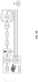
- FIG. 33 depicts an overview of the adaptive camera angle and robot path control approach according to an embodiment.
- the main feedback signal is the signal from the "image feature critic", which takes as input the features extracted from an image feature extractor.
- image feature critic takes as input the features extracted from an image feature extractor.
- the purpose of the image feature extractor is to identify features in the image that are required or desirable for quantifying the desired phenotype.
- the image feature extractor can be designed in two primary ways, first being a heuristic approach wherein certain low-level features and image-level specific features are sought for in the image, such as root-soil view, plant stalk through edge detectors, or corn-ear in the image; alternatively (or in combination), a Neural Network can be used to extract features from the images in a way similar to the Corn-Counting approach.
- the purpose of the image feature critic algorithms and software is to provide a feedback signal to the control system that can be used for controlling the path of the robot and/or the angle of the camera.
- the challenge here is in determining in the most efficient manner whether or not the image has the desired features that are needed.
- the first step is to determine whether or not the image has a feature of interest. This can be accomplished by extracting the feature and comparing it in pixel space with a library of desirable features using various metrics such as sum of average difference, norms in feature spaces, information distances, and/or binary classifiers.
- the most general approach is the classifier-based approach, wherein the potential challenge is in determining whether or not the classifier in itself is sufficiently confident.
- an end-layer support vector machine and/or Gaussian Process with non-Gaussian likelihood algorithms
- Camera Angle-Robot Path Control and Control Blender The purpose of these modules is to control the robot camera angle and/or robot path to ensure that the desired feature(s) are in appropriate view.
- the feedback from the feature critic two clear cases can be envisioned. The first is when the feature is visible, but an adjustment is needed in the angle and/or path to get it in the center of the image. This is accomplished with traditional feedback control mechanisms using image-feature-pixel-distance as a continuous feedback signal. The second case is that the image feature is not in view at all. This requires the robot to search for the feature by adjusting its path and/or camera angle.
- the camera angle sweep method is utilized (in this embodiment), since it is quicker and less risky.
- the camera angle will sweep through all possible angles to find the feature of interest. If this does not lead to the right feature, the robot can utilize its estimate of distance from the row and adjust the distance to values that have previously led to successful image features. If both mechanisms fail to bring the feature in the view, the remote operator can be alerted. Data is recorded, so that over time a learning system can be trained that will get better at ensuring the features stay in view. Future reinforcement learning algorithms will learn with examples the best camera angle and robot path in a field given field features and locations.
- FIG. 27 shows the corn plant population per pot by robot vs human for each dataset.
- the robot predictions agree well with the ground truth.
- the box-and-whisker plot of accuracy for each dataset is shown in FIG.28 .
- the algorithm achieves consistently high accuracy for all locations and growth stages.
- the mean accuracy across all datasets is 89.74%. It is noted that data from Martinsville and Riverside were processed without using the new data to train SVM.
- the results demonstrate that the recognition model generalizes well to unseen data and handles real-world variations effectively.
- Major error sources include heavy occlusion, non-uniform illumination, and corn plants in immediate proximity.
- FIGS. 29A and 29B show two examples of dangling leaves between the rows almost completely covering the camera lens.
- the deep learning algorithm can correctly recognize stalks from leaves, it does not possess the power of making reliable predictions when the camera lens suffers from heavy occlusion.
- a mechanical mechanism such as an air jet [46B] is used to keep leaves away from the vicinity of the visual sensor.
- aspects of the subject disclosure may include, for example, a method for determining a plant population of a field.
- the method of this embodiment comprises capturing, by a camera coupled with a processing system, a group of images associated with a field of plants, wherein the group of images is captured while the camera is in motion in the field.
- the processing system applies a convolutional neural network to the group of images to extract feature vectors.
- the processing system applies a support vector machine to the feature vectors to classify the feature vectors resulting in classified features.
- the processing system applies motion estimation based on a rigid transformation to the classified features resulting in corrected count data.
- the processing system determines a plant population for the field of plants based on the classified features and the corrected count data.
- a method comprising: capturing, by a camera coupled with a processing system that includes a processor, a group of images associated with a field of plants, wherein the group of images is captured while the camera is in motion in the field; applying, by the processing system, a convolutional neural network to the group of images to extract feature vectors; applying, by the processing system, a support vector machine to the feature vectors to classify the feature vectors resulting in classified features; applying, by the processing system, motion estimation based on a rigid transformation to the classified features resulting in corrected count data; and determining, by the processing system, a plant population for the field of plants based on the classified features and the corrected count data.
- the support vector machine comprises a soft margin support vector machine that applies a slack variable to data points on or inside of a correct decision boundary.
- the group of images are not an aerial view of the field of plants, and a view of the camera is at a downward angle.
- the motion of the camera while the group of images is being captured is at a constant velocity.
- the images from the camera are processed to adjust the angle of the camera to improve counting accuracy.
- the images from the camera are processed to adjust the path of the motion of the camera in the field to improve counting accuracy.
- the convolutional neural network is applied only to a fixed region of interest in each image of the group of images.
- the fixed region of interest is automatically computed from the images from the camera.
- the convolutional neural network comprises a standard convolution layer followed by multiple depthwise separable convolution layers.
- data augmentation is applied to training data for the convolutional neural network, and the data augmentation is based on image rotation, image zooming, image vertical shifting, image horizontal flipping, or a combination thereof.
- an apparatus comprising: an unmanned vehicle; a battery supported by the unmanned vehicle; a processing system including a processor and supported by the unmanned vehicle; and a camera supported by the unmanned vehicle, wherein the camera captures a group of images associated with a field of plants, wherein the group of images is captured while the unmanned vehicle travels along rows of the field, and wherein the processing system implements a convolutional neural network, a support vector machine, and motion estimation with respect to the group of images to determine a plant population for the field of plants.
- a view of the camera is at a downward angle.
- the support vector machine comprises a soft margin support vector machine that applies a slack variable to data points on or inside of a correct decision boundary.
- the unmanned vehicle travels along the rows of the field at a constant velocity.
- the camera mounted on the unmanned vehicle is on a gimbal that automatically adjusts the view of the camera based on the images from the camera.
- the convolutional neural network is applied only to a fixed region of interest in each image of the group of images.
- the convolutional neural network comprises a standard convolution layer followed by multiple depthwise separable convolution layers.
- data augmentation is applied to training data for the convolutional neural network, and the data augmentation is based on image rotation, image zooming, image vertical shifting, image horizontal flipping, or a combination thereof.
- an air jet is supported by the unmanned vehicle, wherein the air jet clears obstructions such as leaves from the frame of the camera.
- a non-transitory machine-readable storage medium comprising executable instructions that, when executed by a processing system including a processor, facilitate performance of operations, comprising: applying a convolutional neural network to a group of images to extract feature vectors, wherein the group of images is associated with a field of plants and is captured while a camera is in motion in the field; applying a support vector machine to the feature vectors to classify the feature vectors resulting in classified features; applying motion estimation based on a rigid transformation to the classified features resulting in corrected count data; and determining a plant population for the field of plants based on the classified features and the corrected count data.
- the support vector machine comprises a soft margin support vector machine that applies a slack variable to data points on or inside of a correct decision boundary.
- the group of images are not an aerial view of the field of plants, and a view of the camera is at a downward angle.
- the convolutional neural network is applied only to a fixed region of interest in each image of the group of images.
- the convolutional neural network comprises a standard convolution layer followed by multiple depthwise separable convolution layers.
- data augmentation is applied to training data for the convolutional neural network, and the data augmentation is based on image rotation, image zooming, image vertical shifting, image horizontal flipping, or a combination thereof.
- an agricultural robot that (in various embodiments) enables field-based phenotyping which overcomes previous limitations such as high operational and maintenance costs, low coverage area, safety, disruptive internal combustion engines, excessive manual or off-board processing of sensor data, and/or the need for experienced operators.
- an ultralight, low-cost, autonomous, field-phenotyping robot that can navigate in a variety of field conditions to overcome the aforementioned limitations with existing field-based phenotyping systems.
- the variability in crop rows, topology, environmental conditions and/or size can be overcome by an agricultural robot that is capable of traversing a plurality of crops in different geographies without damaging the crop-plants for phenotyping, scouting, and/or during crop management operations.
- an agricultural robot When plants are very small or when rows are unstructured or very tightly spaced, the agricultural robot can traverse the field without damaging the crop-plants, even if it has to drive over them, and have low cost of ownership.
- an agricultural robot is manufactured and/or operates with a low cost for robotic scouting, phenotyping, and/or crop-management tasks, which can be significant given the cost pressure faced by farmers.
- an additive manufacturing process manufactured apparatus can traverse or operate in a plurality of crops, agricultural environments, and/or geographies without damaging the crops and at sufficiently low cost.
- the apparatus can be cost effectively manufactured and operated, while also being capable of fully automated stand-counting and phenotyping.
- a plastic built or composite material manufactured apparatus can traverse or operate in a plurality of crops, agricultural environments, and/or geographies without damaging the crops and at sufficiently low cost.
- the apparatus can be cost effectively manufactured and operated, while also being capable of fully automated stand-counting and phenotyping.
- a metal manufactured apparatus can traverse or operate in a plurality of crops, agricultural environments, and/or geographies without damaging the crops and at sufficiently low cost.
- the apparatus can be cost effectively manufactured and operated, while also being capable of fully automated stand-counting and phenotyping.
- plastic, metal, composites, or other material is used in combination to build the robot.
- the robot may be constructed of compliant or soft materials.
- an apparatus that will not damage crops even if it drives over them, and does not utilize contact sensors to determine row edges or paths.
- an autonomous ground robot is provided that is capable of tracking a pre-specified path with a high level of accuracy without human intervention.
- an autonomous ground robot can also incorporate other higher-level behaviors, such as autonomously deciding when to recharge, and/or collaborating with other autonomous ground robots to complete a task.
- small ground robots are mechanized rovers that can autonomously track pre-specified paths in harsh outdoor environments. Their small size enables them to maneuver through rows and avoid issues such as soil-compaction, through use of compact, lightweight, and energy efficient driving, sensing, and autonomy technologies.
- an agricultural robot that performs agricultural scouting and/or phenotyping measurements and that does not permanently damage plants even if it drives over them. This is enabled through various features including one or more of: an ultra-light robotic platform (e.g., a robot weighing less than 20lbs); ultra-compact construction (e.g.
- a robot that is compact in size a robot that is low complexity, battery operated, with hours of endurance leading to low manufacturing and operational cost; a robot that does not damage plants even if it drives over them; a robot that includes compact sensing, computation, and onboard-analytics suite to perform agronomically relevant tasks and measurements onboard, including stand-counting, stalk angle determination, disease detection, and others on an ultra-light robotic platform; a robot that can utilize a web-based analytics suite to perform these measurements and/or enhance onboard measurement capability; an autonomous path following system that ensures highly precise position tracking, which ensures the robot stays on a prescribed path to minimize trampling over plants; an autonomous path following system that does not need high-precision RTK GPS signal; a human-interaction GUI (graphical user interface) implemented as an application on a smart-device that enables a single human operator to control or direct one or more autonomous agricultural robots; an ultra-compact robot that can turn around 180° in a crop row; and/or a turning mechanism not reliant upon
- One embodiment provides an apparatus having a frame, wheels rotatably connected with the frame, and a battery connected with the frame.
- the apparatus can have electric motors supported by the frame and connected to the battery, where each of the electric motors is connected with one of the wheels, wherein the electric motors allow the apparatus to rotate at least 180 degrees (e.g. to rotate 180 degrees within the space between adjacent rows of crops).
- the apparatus can have a processor supported by the frame, and velocity sensors supported by the frame and coupled with the processor, where each of the velocity sensors is connected with one of the wheels, and where the velocity sensors transmit velocity feedback signals associated with each of the wheels to the processor.
- the apparatus can have a global navigation satellite system (GNSS) supported by the frame and comprising a GNSS antenna and GNNS computer coupled with the processor, where the global navigation satellite system receives, processes and transmits positional information to the processor.
- GNSS global navigation satellite system
- the apparatus can have a gyroscope supported by the frame and coupled with the processor, where the gyroscope transmits measurement signals including yaw rate measurements to the processor.
- the apparatus can have a group of sensors supported by the frame, where the group of sensors provide contact-less measurements of surrounding crops and their characteristics for navigation purposes.
- the apparatus can have a group of sensors supported by the frame and coupled with the processor, where the group of sensors collect phenotypic data associated with crops.
- the processor determines control signals based on desired angular and linear velocities according to the velocity feedback signals, the positional information and the measurement signals by applying a real-time receding horizon estimation and control.
- the processor transmits the control signals for each of the electric motors thereby causing the apparatus to track a reference path.
- Another embodiment provides an apparatus having a frame, wheels rotatably connected with the frame, and a battery connected with the frame.
- the apparatus can have electric motors supported by the frame and connected to the battery, where each of the electric motors is connected with one of the wheels, wherein the electric motors allow the apparatus to rotate at least 180 degrees (e.g. to rotate 180 degrees within the space between adjacent rows of crops).
- the apparatus can have a processor supported by the frame.
- the apparatus can have velocity sensors supported by the frame and coupled with the processor, where each of the velocity sensors is connected with one of the wheels, and where the velocity sensors transmit velocity feedback signals associated with each of the wheels to the processor.
- the apparatus can have a global navigation satellite system supported by the frame and comprising a GNSS antenna and GNNS computer coupled with the processor, where the global navigation satellite system receives, processes and transmits positional information to the processor.
- the apparatus can have a gyroscope supported by the frame and coupled with the processor, where the gyroscope transmits measurement signals including yaw rate measurements to the processor.
- the apparatus can have a group of sensors supported by the frame and coupled with the processor, where the group of sensors collect phenotypic data associated with crops.
- the processor determines control signals based on desired angular and linear velocities according to the velocity feedback signals, the positional information and the measurement signals.
- the processor transmits the control signals for each of the electric motors thereby causing the apparatus to track a reference path.
- the processor generates data collection signals to select or adjust one or more data collection algorithms, one or more of the group of sensors or a combination thereof thereby adjusting the collection of the phenotypic data associated with crops.
- the data collection signals can be generated by the processor according to an analysis of at least some of the phenotypic data, other information obtained by the processor, or a combination thereof.
- the data collection signals can be generated by the processor without receiving command signals from a user at a remote source.
- Yet another embodiment provides a method including receiving, by a processing system of an agricultural robot having wheels, velocity feedback signals associated with each of the wheels, where the velocity feedback signals are received from velocity sensors of the agricultural robot, and where each of the velocity sensors is connected with one of the wheels.
- the method can include receiving, by the processing system, positional information from a global navigation satellite system (GNSS) of the agricultural robot.
- GNSS global navigation satellite system
- the method can include receiving, by the processing system, measurement signals from a gyroscope of the agricultural robot, where the measurement signals include yaw rate measurements.
- the method can include determining, by the processing system, controls signals based on desired angular and linear velocities according to the velocity feedback signals, the positional information and the measurement signals by applying a real-time receding horizon estimation and control.
- the method can include transmitting, by the processing system, the control signals to a controller coupled with electric motors thereby causing the agricultural robot to track a reference path, where each of the electric motors is connected with one of the wheels and enable the agricultural robot to rotate at least 180 degrees (e.g. to rotate 180 degrees within the space between adjacent rows of crops).
- FIG.36 an illustration of an embodiment of the robot with a suite of sensors attached is shown.
- This robot is ultralight (less than 15lbs) and compact.
- the ultralight nature of the robot ensures that it does not drive plants into the ground due to weight, and minimizes the momentum of the robot as it drives.
- Agricultural robots out in the market are typically significantly heavier.
- the ultralight weight is based on the selection of material, the constitution of the material, and the structural design. Conventional wisdom for agricultural equipment is to manufacture them out of metal. However, metal is heavy and expensive.
- this embodiment of the robot is built through additive manufacturing (such as 3D printing). Additive manufacturing creates complex designs by layering material, as opposed to traditional metal working, or traditional injection molding of plastics.
- the robot includes parts in a shape to optimally distribute stress.
- the layering mechanism in the additive manufacturing is utilized to control the density, so that denser and stronger construction is utilized for high stress and high wear parts.
- Additive manufacturing techniques can be applied to different parts based on their expected wear and stress levels.
- the robot can include selected low-weight metal components, which are selected to maximize the field-endurance of the robot.
- the ground clearance of the robot is sufficiently high to enable traversing complex terrain.
- the motors can be placed sufficiently close to the robot wheels, to minimize loss in transmission.
- near-wheel mechanisms can be utilized that ensure little stress is put on the motors and the power is transmitted directly to the wheels with minimal (if any) gears and transmission system to minimize losses.
- wheels are utilized that strike a performance compromise between traction, pressure on soil, propensity to displace soil, sufficient ground clearance, manufacturing ease, and mechanical strength.
- FIG. 37 shows some of the wheels that were determined to be undesirable in operation. The left most wheel failed because of low ground clearance and too much pressure on the soil. The middle wheel failed due to too much soil disturbance and damage to plants due to sharp edges (leading to excessive pressure). The right wheel failed because of too much slippage due to lack of traction causing damage. Other considerations include using the correct manufacturing in-fill patterns to create sufficient softness in the wheels even when they are additive manufactured.
- FIG. 38 shows an internal electronics layout according to an embodiment (this FIG depicts how a complex suite of electronics can be integrated into a very small robot).
- the robot electronics suite maximizes or increases robot endurance between charges, optimizes or increases space utilization, minimizes or reduces interference between devices, and ensures or promotes that the high performance electronics remain sufficiently cool.
- one global navigation satellite system (GNSS) antenna is mounted straight up the center of the robot, and the dual-frequency GPS-capable real-time kinematic differential GNNS module (Piksi Multi, Swift Navigation, USA) is used to acquire centimeter-level accurate positional information at a rate of 5 Hz.
- Another antenna and module is used as a portable base station and transmits differential corrections.
- a 3-axis gyroscope (STMicroelectronics L3G4200D) is used to obtain yaw rate measurements with an accuracy of 1 degree per second at a rate of 5 Hz.
- the system can be modular with any RTK GPS enabled antenna.
- a two-channel Hall-effect encoder for each DC motor can be attached to measure velocities of the wheels.
- a Sabertooth motor controller e.g., Dimension engineering, USA
- a Kangaroo x2 motion controller e.g., Dimension engineering, USA
- a Kangaroo x2 motion controller can be utilized which is a two channel self-tuning PID controller that uses feedback from the encoders to maintain desired linear and angular robot velocity commands.
- a 1.2GHz, 64bit, quad-core Raspberry Pi 3 Model B CPU acquires measurements from all available sensors, and sends desired command signals (e.g., desired linear and angular velocities) to the Kangaroo x2 motion controller in the form of two Pulse-width modulation signals.
- the robot estimates its global position by feeding any available measurements from all its on-board sensors (GPS, gyroscope, and encoders) to an online state estimator.
- every time estimated states are updated, they can be fed to a path following controller which uses these estimated states to calculate the desired linear and angular velocities, in the body-frame, needed by the robot in order to follow the reference path given by a trajectory generator.
- a cooling system can provide liquid cooling to the NVIDIA Tegra GP-GPU. This cooling system can have an external mounted radiator that is mounted in a way to avoid obstructing the wheels during motion.
- a top view schematic of the robot of this embodiment is illustrated showing the center of gravity (CG) and the DC motors/encoders (only one of which is labeled) that enables a desired level of control for traversing crop rows.
- the wheels can be critical in ensuring the robot can navigate over crops without damaging them, and can navigate over wet and muddy terrains.
- the wheels can have spade-like extensions, structures or arrangements that are designed to provide good traction on loose soils, while minimizing contact area. These spade-like extensions can extend from the wheel and circumscribe the wheel to make contact with the soil.
- this wheel has significant advantages: (1) it does not lead to a large area that is put under pressure and force as the robot moves, rather limits it only to a small contact area; (2) it is much simpler to manufacture and operate in the field; and (3) it is modular, in the sense that each wheel can be replaced if it breaks, instead of having to replace the whole track.
- the driving mechanism can include motors mounted near each wheel to enable four wheel independent drive without the need to distribute power from a central power unit. This is very different than typical existing equipment and vehicles, which often utilize a single power plant and then transmit the power to different wheels.
- the four wheel drive mechanism can enable the robot to turn by varying the speeds of independent wheels. This is a much simpler mechanism since it does not require complex rack-and-pinion or other similar mechanisms for driving.
- Another feature of the wheel and mount is the embedding (in one example) of suspension without having to increase the size of the robot.
- the suspensions can be embedded between the wheel mount and the chassis. This has the benefit that the chassis can be broadened, while also enabling a simple mechanism to handle bumpy agricultural fields.
- FIGS. 41A-41E depict an embodiment of a robotic platform built mostly out of 3D printed parts (instead of mostly out of metal parts), which is battery operated (Lithium-Polymer batteries), and features a tightly integrated suite of sensors, computing devices, memory, and software for control and onboard analytics for scouting.
- the total cost of this robot is an order of magnitude smaller than typical existing agricultural robots, including commercially available options and many academic prototypes. Furthermore, the robot is also much more compact than many existing robots.
- the robot of this embodiment is capable of turning around 180° in a crop row.
- FIGS. 42A-42D depict dimensions for an embodiment of the robot.
- the robot has a mechanism to include suspension to the wheels of the robot.
- This robot is equipped with two sideward facing visual spectrum cameras, one forward facing camera, and an Intel RealSense 3D sensor.
- the robot can also include LED lighting to aid operation in shaded areas.
- a Paralyne coating can be provided for water resistance, wherein a benefit of this approach is that it does not significantly add to the weight or form-factor of the robot while providing water resistance.
- the robot can provide autonomous path following with high accuracy.
- the robot is fully autonomous, capable of following predefined trajectories with a high level of accuracy. Accurate steering through crop rows avoids crop damage, and is one of the most important features for an agricultural robot.
- the robot of this embodiment implements RHEC-based navigation applied to a fully autonomous mobile platform that has been rigorously evaluated in realistic field conditions to yield far less than 5 inches of path tracking error.
- the guidance and control system fuses the measurements from an inertial sensor (gyroscope) with RTK-GPS and uses nonlinear model predictive control to execute the path tracking control. All four wheels are independently controlled.
- a real-time receding horizon estimation and control (RHEC) framework is developed and implemented on an embedded computer.
- RHE receiving horizon estimation
- RHC receiving horizon control
- the capabilities of the real-time RHEC framework are verified experimentally and the results show an accurate tracking performance on a bumpy and wet soil field as illustrated in FIG.43 .
- the mean values of the Euclidean error and required computation time of the RHEC framework are respectively equal to 1.66 inches and 0.88 milliseconds.
- an agricultural robot is provided with shape, form, weight and material such that it does not damage plants even if it drives over them or brushes against them during operation throughout the season, from plant emergence to post harvest.
- a locomotion mechanism for the robot enables it to traverse agricultural fields without damaging plants.
- An autonomous navigation system comprising sensors, computers, and actuators enables the robot to plan and drive on a path in the agricultural field that does not damage crop-plants, and plan and conduct crop management actions in a manner that does not damage crop-plants.
- the robot can be provided with an embedded sensor system, algorithms, and software for onboard agronomic functions without requiring cloud connectivity or connectivity to other computers/robots.
- the robot can perform various data collection functions including stand counts, stalk angle estimation, ear height and plant height estimation, disease identification (e.g., rust, mosaic, fungal), insect damage identification (e.g., leaf damage, stalk damage, insect nest identification), insect detection, plant and soil sampling and/or retrieving samples that can be returned to a ground station.
- the robot can include a communication and coordination system that enables a remote user to control one or more autonomous robots in a manner such that crop-plants are not damaged.
- the communication and coordination system can enable a team of robots to communicate and collaborate to obtain agronomic measurements without damaging crop-plants, by determining least damaging paths and allocating portions of the field to specific robots to reduce areas traveled and increase speed of obtaining agronomic information.
- the communication and coordination system enables a team of robots to communicate and collaborate to conduct field management, including but not limited to one or more of weeding, culling, sampling, spraying, pruning, harvesting without damaging crop-plants, by determining least damaging paths and allocating portions of the field to specific robots to reduce areas traveled and increase speed of conducting management tasks.
- a field deployed automatic recharging system that enables the robot to recharge its batteries via including but not limited to one or more of a connected recharge, inductive recharge, battery swap, or wireless charging.
- a field deployable robot is capable of assisting other robots through activities such as repairing, rescuing, or recharging other robots in a manner that does not damage crop-plants.
- a real-time receding horizon estimation and control (RHEC) framework can be applied to a fully autonomous field robot to increase its steering accuracy.
- RHC nonlinear receding horizon control
- RHE receding horizon estimation
- a real-time RHEC framework is developed and applied to a fully autonomous mobile robotic platform for in-field phenotyping applications, such as in Sorghum fields (although the embodiments can be utilized in various fields having various crops).
- RHE can be used to estimate constrained states and parameters, and is formulated below: where ⁇ , u, p and z are respectively the state, input parameters and output vectors.
- RHC is designed based on the adaptive system model with time-varying parameters and formulated below:
- a 3D printed field robot such as shown in FIGS. 43A-43D, can be formulated with the following equations: where x and y denote the position of the field robot, ⁇ denotes the yaw angle, v denotes the speed, ⁇ denotes the yaw rate, and ⁇ and ⁇ denote the traction parameters.
- the results show an accurate tracking performance on a bumpy and wet soil field (see FIGS. 44A and 44B ).
- the mean values of the Euclidian error for the RHCs based on the RHE and the EKF are 0.0423 m and 0.0514 m, respectively.
- the RHEC framework benefits from traction parameter estimates and results in less error compared to the RHC based on the EKF.
- the available space on either side of the robot (of this embodiment) is limited to only 0.12 m; therefore, the error must be smaller than this limit to avoid crop damage and keep the robot centered in the row.
- the results of multiple experiments indicated that the RHEC framework does not violate this error constraint, while the RHC based on the EKF violates it 17 times during the path tracking of straight lines. This demonstrates the capability of the RHEC framework.
- the required computation time of the RHEC framework are respectively equal to 0.88 ms.
- the derivative of ⁇ with respect to t is denoted by ⁇ ⁇ R " ⁇ .
- FIG.40 A schematic diagram of a 3D printed field robot of an embodiment is illustrated in FIG.40 .
- An adaptive nonlinear kinematic model is derived for the 3D printed field robot as an extension of the traditional kinematic model as follows: where x and y denote the position of the field robot, ⁇ denotes the yaw angle, ⁇ denotes the speed, v denotes the yaw rate, and ⁇ and k denote the traction parameters.
- the difference between the traditional and developed model above is two slowly changing traction parameters. These parameters provide for minimizing deviations between the real-time system and 3D printed field robot with an online parameter estimator. It is noted that they must be (in this embodiment) between zero and one.
- the RHE approach has a capability of dealing with constraints on state and parameter and formulated for the 3D printed robot (of this embodiment) as follows: where the deviations of the states and parameters estimates before the estimation horizon are minimized by a symmetric positive semi-definite weighting matrix HN, and the deviations of the measured and system outputs in the estimation horizon are minimized by a symmetric positive semidefinite weighting matrix Hk.
- the estimation horizon is represented by N, and lower and upper bounds on the traction parameters ⁇ k parameters are respectively defined as 0 and 1.
- the objective function in the RHE formulation consists of two parts: the arrival and quadratic costs. The arrival cost stands for the early measurements: and the quadratic cost stands for the recent measurements:
- the inputs to the RHE algorithm are the position values coming from the GNNS, the velocity values coming from the encoders mounted on the DC motors and the yaw rate values coming from the gyro.
- the outputs of RHE are the position in x- and y-coordinate system, the yaw angle, the velocity and the traction coefficients.
- the estimated values are then fed to the RHC.
- the RHC approach is usable for a system with fast dynamics. The reason is that RHC has capability of dealing with hard constraints on state and input, and online optimization allows updating cost, model parameters, constraints.
- the following finite horizon optimal control formulation for the 3D printed robot (of this embodiment) is solved to obtain the current control action by using current state of the system as initial state: where Q k ⁇ R n ⁇ ⁇ n ⁇ , R ⁇ R n u ⁇ n u and Q N ⁇ R n ⁇ ⁇ n ⁇ are symmetric and positive semi-definite weighting matrices, ⁇ r and u r are the state and input references, ⁇ and u are the states and inputs, t k is the current time, N is the prediction horizon, ⁇ (t k ) is the current estimates.
- the first term in the cost function is the stage cost and it is the cost throughout the prediction horizon.
- the second term in the cost function is the terminal penalty and it is the cost at the end of the
- the first element of the optimal controls sequence is applied to the system: and then the procedure is repeated for future sampling times by shifting prediction horizon for the subsequent time instant. It is important to remark that the control input u *( t k +1 ) is precisely the same as it would be if all immeasurable states and parameters acquire values equal to their estimates based on the estimation up to current time t k due to the certainty equivalence principle.
- the yaw rate reference can be calculated from the reference trajectory as the yaw angle reference.
- steady state error may occur in the case of a mismatch between the system model and 3D printed robot. Therefore, the recent measured yaw rate is used as the input reference to penalize the input rate in the objective function discussed herein.
- an agricultural robot that does not damage crop-plants even if it drives over them through use of a weight of the robot being significantly small, even though the robot can withstand harsh field conditions; the material that the robot is built from provides the right strength-to-weight ratio, and does not damage plants; the structure of the robot has appropriate ground clearance, lack of sharp edges, and appropriate wheel design to be able to drive over plants without damaging them; control and analytics algorithms take into account the physical constraints of the robot and its environment; and/or the manufacturability of the robot, the operating paradigm, and/or the use case reduces or minimizes cost of manufacturing, operation, and/or ownership.
- the various embodiments can be modified, reduced, or enhanced.
- the sensing functions can be dynamically implemented or otherwise controlled.
- different groups of sensors can be actuated based on various factors, such as weather, crop type, location, size of crops, speed of robot, and so forth.
- the dynamic control of the sensing functions can be autonomous without user actuation.
- the dynamic control of the sensing functions can be based on user actuation or can be initiated after user authorization, such as a user responding to a message from the robot suggesting that a particular sensor or algorithm be actuated or executed.
- data collected by the robot can trigger collection of different data.
- a robot can detect a condition associated with crops and can actuate one or more sensors that attempt to detect causes for that condition (e.g., disease, insects, and so forth).
- the triggering of a new data collection technique by the robot can be autonomous without user actuation; based on user actuation; or can be initiated after user authorization, such as a user responding to a message from the robot suggesting that a particular sensor or algorithm be actuated or executed.
- one robot can provide notice to other robot(s) and/or to a central processing system indicating particular data that should be retrieved. For example, a first robot can collect data indicating the existence of a particular condition based on a threshold comparison associated with the collected data. The first robot can then wirelessly transmit a message to one or more second robots (with or without notice or authorization from a user) to cause the second robots to commence collecting the same data associated with the condition.
- the robot can be part of a group of robots that are collecting data at a location.
- the group of robots can be in a master/slave relationship so that one or more master robots can control one or more slave robots, such as control over types of data collection, navigation paths, operational parameters (e.g., speed), and so forth.
- the group of robots can be similar robots with similar operational capabilities (such as the ability to collect the same types of data).
- the group of robots can be different robots with one or more different operational capabilities (such as the ability to collect different types of data).
- the robot can implement different algorithms for the data collection based on determined factors, such as time, location, weather, robot speed, data received from other sources (e.g., other robots, intelligent agricultural equipment, and so forth).
- a group of robots can collaborate to provide an optimized and/or efficient data collection technique to a particular location.
- the location can be divided into portions where each available robot performs all data collection for that portion.
- the portions may be of different sizes depending on different speeds of the robots.
- the data collection can be divided into tasks where each available robot performs some of the tasks for all or some of the location.
- the tasks may be shared between some robots and the robots may be selected based on the capabilities, such as speed, processing resources, sensing components, and so forth.
- historical information can be utilized by the robot to adjust its operations. For example, the robot may select a particular group of data to be collected based on historical information indicating that the crop has been previously susceptible to a particular insect or disease.
- the historical information can be obtained from various sources, including other robots at other locations.
- the robot can travel at a velocity of 1 mph, 2-3 mph and/or 4-5 mph.
- the robot and/or team of robots and/or a web-based computer uses machine learning to: detect and identify agriculturally relevant phenomena using data from single or plurality of sensors, such as weeds, stressors, insects, diseases etc.; and/or to measure agronomic quantities, such as stem width, stand count, plant height, ear height etc.
- aspects of the subject disclosure may include, for example, an apparatus having a processing system that receives velocity feedback signals associated with each of the wheels of the apparatus, that receives positional information from a global navigation satellite system of the apparatus, that receives measurement signals from a gyroscope of the apparatus, that determines control signals based on desired angular and linear velocities according to the velocity feedback signals, the positional information and the measurement signals by applying a real-time receding horizon estimation and control, and that transmits the control signals to a controller coupled with electric motors thereby causing the apparatus operating as an agricultural robot to track a reference path, where each of the electric motors is connected with one of the wheels and enable the agricultural robot to rotate 180 degrees. Additional embodiments are disclosed.
- an apparatus comprising: a frame; wheels rotatably connected with the frame; a battery connected with the frame; electric motors supported by the frame and connected to the battery, wherein each of the electric motors is connected with one of the wheels, wherein the electric motors allow the apparatus to rotate 180 degrees; a processor supported by the frame; velocity sensors supported by the frame and coupled with the processor, wherein each of the velocity sensors is connected with one of the wheels, wherein the velocity sensors transmit velocity feedback signals associated with each of the wheels to the processor; a global navigation satellite system (GNSS) supported by the frame and comprising a GNSS antenna and GNNS computer coupled with the processor, wherein the global navigation satellite system receives, processes and transmits positional information to the processor; a gyroscope supported by the frame and coupled with the processor, wherein the gyroscope transmits measurement signals including yaw rate measurements to the processor; and a group of sensors supported by the frame and coupled with the processor, wherein the group of sensors collect phenotypic data
- the apparatus weighs less than 20 lbs.
- each of the wheels includes spade structures that circumscribe the wheel and selectively contact soil.
- the processor transmits the control signals without receiving command signals from a user at a remote source.
- the battery is chargeable by a deployable charging device via inductive recharging, wireless recharging, a hardwire connection, or a combination thereof.
- the processor selects an algorithm from among a group of algorithms associated with one of the group of sensors without receiving command signals from a user at a remote source.
- the processor selects an algorithm from among a group of algorithms associated with one of the group of sensors according to an analysis of at least some of the phenotypic data and without receiving command signals from a user at a remote source.
- the processor actuates one of the group of sensors without receiving command signals from a user at a remote source.
- the processor actuates one of the group of sensors according to an analysis of at least some of the phenotypic data and without receiving command signals from a user at a remote source.
- the processor transmits a command signal to another apparatus, wherein the command signal causes the other apparatus to select an algorithm from among a group of algorithms, actuate a sensor or a combination thereof, wherein the other apparatus is an autonomous agricultural robot that collects data associated with the crops.
- the processor generates the command signal according to an analysis of at least some of the phenotypic data and without receiving other command signals from a user at a remote source.
- the apparatus is part of a group of apparatuses that each operate as autonomous agricultural robots that collect the phenotypic data associated with the crops, wherein the group of apparatuses communicate with each other for assigning data collection paths, data collection tasks, or a combination thereof.
- the group of apparatuses are in a master device/slave device relationship that enables one or more master devices of the group of apparatuses to control one or more slave devices of the group of apparatuses.
- the processor receives a remote control signal from a remote source that causes the processor to adjust operation of the apparatus.
- components of the apparatus including the frame are made from 3D printed material.
- an apparatus comprising: a frame; wheels rotatably connected with the frame; a battery connected with the frame; electric motors supported by the frame and connected to the battery, wherein each of the electric motors is connected with one of the wheels, wherein the electric motors allow the apparatus to rotate 180 degrees; a processor supported by the frame; velocity sensors supported by the frame and coupled with the processor, wherein each of the velocity sensors is connected with one of the wheels, wherein the velocity sensors transmit velocity feedback signals associated with each of the wheels to the processor; a global navigation satellite system (GNSS) supported by the frame and comprising a GNSS antenna and GNNS computer coupled with the processor, wherein the global navigation satellite system receives, processes and transmits positional information to the processor; a gyroscope supported by the frame and coupled with the processor, wherein the gyroscope transmits measurement signals including yaw rate measurements to the processor; and a group of sensors supported by the frame and coupled with the processor, wherein the group of sensors collect phenotypic data
- the other information obtained by the processor comprises historical phenotypic data associated with a location of the crops, weather information, time information, or a combination thereof.
- the apparatus weighs less than 20 lbs, and each of the wheels includes spade structures that circumscribe the wheel and selectively contact soil.
- a method comprising: receiving, by a processing system of an agricultural robot having wheels, velocity feedback signals associated with each of the wheels, wherein the velocity feedback signals are received from velocity sensors of the agricultural robot, wherein each of the velocity sensors is connected with one of the wheels; receiving, by the processing system, positional information from a global navigation satellite system (GNSS) of the agricultural robot; receiving, by the processing system, measurement signals from a gyroscope of the agricultural robot, wherein the measurement signals include yaw rate measurements; determining, by the processing system, controls signals based on desired angular and linear velocities according to the velocity feedback signals, the positional information and the measurement signals by applying a real-time receding horizon estimation and control; and transmitting, by the processing system, the control signals to a controller coupled with electric motors thereby causing the agricultural robot to track a reference path, wherein each of the electric motors is connected with one of the wheels and enable the agricultural robot to rotate 180 degrees.
- GNSS global navigation satellite system
- the method further comprises: receiving, by the processing system from a group of sensors of the agricultural robot, phenotypic data associated with crops; and generating, by the processing system, data collection signals to select or adjust one or more data collection algorithms, one or more of the group of sensors or a combination thereof thereby adjusting the collection of the phenotypic data associated with crops, wherein the data collection signals are generated by the processing system according to an analysis of at least some of the phenotypic data, other information obtained by the processing system, or a combination thereof, and wherein the data collection signals are generated by the processing system without receiving command signals from a user at a remote source.
- the system can include a small autonomous robot 4502 (e.g., under 50 lb and/or less than 20 inches) with multiple sensors and actuators.
- the system can include a replaceable canister 4504 containing liquid, that can be pressurized, and/or that can have multiple chambers containing different liquids.
- the canister can be configured for mounting on, to and/or in the robot 4502.
- the canister can be configured for towing behind the robot 4502 (e.g., on a trailer, not shown).
- the system can include mechanisms for accepting one or more canisters (e.g., two).
- the system can include mechanisms for spraying the liquid including one or more replaceable nozzle(s).
- the mechanism can include a pressurization system.
- the system can include an actuator system having one or more actuators for operating the mechanism for spraying (e.g., four), control the rate, duration, direction, and force of spray.
- the system can include a liquid pressurization system that can include motors, pumps, canisters of pressurized gases (e.g., CO2, N, or others).
- the system can include a remote operator interface connected via a network enabling a user to control the robot and spraying, including the ability to upload a prescription from another device on an interconnected network.
- the robot can have the capability to follow the prescribed path autonomously and spray according to prescription.
- the robot can have the capability to automatically decide when, what, and where to spray by analyzing agronomic quantities through on-board sensors while following scouting paths autonomously.
- the system can generate an optimal path based on field conditions and/or data from other connected devices (e.g., the apparatus of FIG.36 ) to achieve prescription targets and/or mission objectives.
- the system can adapt the path and spraying prescription using data obtained by on-board sensors and/or other connected devices to satisfy higher-level mission objectives, such as find and spray appropriate chemicals on plants with specific disease.
- the system can perform one or more of the above-described features with or without user interaction with the system.
- a drone e.g., robot
- the path taken by the drone during the first stage can be the same as the path taken by the drone during the second stage.
- the path taken by the drone during the second stage can be different from the path taken by the drone during the first stage.
- the drone can be equipped with a sprayer attachment (or other such device) and the confirmation can be based upon some level of machine learning that had been carried out in the past (e.g., prior to the second stage).
- a swarm (or group) of drones could work together. For instance, one or a few drones can first collect data on one (or more) first stage paths (as discussed above). The collected data can then be analyzed (the analysis can be performed on-board one or more of the drones and/or on a ground-based computational platform). Next, one or more different drones carrying the chemical(s) necessary to treat problem(s) in each of the identified area(s) can go to area(s) to treat one or more problems.
- the robot(s) applying treatment are the same one(s) that did the identification (e.g., the identification of an anomaly).
- the robot(s) applying treatment are different from the one(s) that did the identification (e.g., the identification of an anomaly).
- the term drone can refer to any small robot, whether aerial or ground based.
- a communication system can enable a device (e.g., a mobile robot) to wirelessly communicate (e.g., bi-directionally) with a remote computer from which the device can receive one or more instructions and/or send information,
- a device e.g., a mobile robot
- wirelessly communicate e.g., bi-directionally
- a remote computer from which the device can receive one or more instructions and/or send information
- a size and/or a location of a window associated with foreground extraction can be changed.
- the size and/or location can be changed by an onboard computer or processor (e.g., onboard a mobile robot).
- the size and/or location can be communicated to the device (e.g., mobile robot) by an external computer or processor.
- a support vector machine can comprise a soft margin support vector machine that applies a slack variable to data points on or inside of a correct decision boundary.
- estimation of width can comprise using foreground extraction and/or LIDAR depth estimate(s).
- a distance to a row can be estimated using a single ranging device or a plurality of ranging devices.
- the ranging device or devices can emit electromagnetic, laser, infra-red, and/or acoustic waves.
- a device e.g., mobile robot
- the device e.g., mobile robot
Landscapes
- Engineering & Computer Science (AREA)
- Physics & Mathematics (AREA)
- General Physics & Mathematics (AREA)
- Theoretical Computer Science (AREA)
- Computer Vision & Pattern Recognition (AREA)
- Radar, Positioning & Navigation (AREA)
- Remote Sensing (AREA)
- Aviation & Aerospace Engineering (AREA)
- Automation & Control Theory (AREA)
- Multimedia (AREA)
- Software Systems (AREA)
- Data Mining & Analysis (AREA)
- Life Sciences & Earth Sciences (AREA)
- Artificial Intelligence (AREA)
- Evolutionary Computation (AREA)
- General Engineering & Computer Science (AREA)
- Electromagnetism (AREA)
- Mathematical Physics (AREA)
- Signal Processing (AREA)
- Computing Systems (AREA)
- Medical Informatics (AREA)
- Computer Networks & Wireless Communication (AREA)
- Evolutionary Biology (AREA)
- Bioinformatics & Computational Biology (AREA)
- Computational Linguistics (AREA)
- Health & Medical Sciences (AREA)
- General Health & Medical Sciences (AREA)
- Bioinformatics & Cheminformatics (AREA)
- Soil Sciences (AREA)
- Mechanical Engineering (AREA)
- Geometry (AREA)
- Environmental Sciences (AREA)
- Management, Administration, Business Operations System, And Electronic Commerce (AREA)
- Image Processing (AREA)
- Investigating Or Analysing Materials By Optical Means (AREA)
- Image Analysis (AREA)
Claims (15)
- Vorrichtung umfassend:ein Verarbeitungssystem, das einen Prozessor einschließt;ein Kommunikationssystem, das der Vorrichtung ermöglicht, drahtlos mit einem entfernten Computer zu kommunizieren, von dem die Vorrichtung Anweisungen empfangen und Informationen senden kann, undeinen Speicher, der ausführbare Anweisungen speichert, die, wenn sie durch das Verarbeitungssystem ausgeführt werden, Operationen durchführen, wobei die Operationen umfassen:Erlangen von Videodaten von einer einzelnen monokularen Kamera, wobei die Videodaten eine Vielzahl von Einzelbildern umfassen, wobei die einzelne monokulare Kamera an einem mobilen Bodenroboter angebracht ist, der sich entlang einer Spur bewegt, die durch eine Reihe von Kulturen definiert ist, wobei der mobile Bodenroboter eine Vielzahl von Rädern und eine Vielzahl von Codierern umfasst, wobei jedem der Vielzahl von Rädern ein jeweiliger der Vielzahl von Codierern zugeordnet ist, wobei die Reihe von Kulturen einen ersten Pflanzenstängel umfasst und wobei die Vielzahl von Einzelbildern eine Darstellung des ersten Pflanzenstängels einschließt;Erlangen von Robotergeschwindigkeitsdaten von der Vielzahl von Codierern, wobei die Robotergeschwindigkeitsdaten auf der Grundlage eines Durchschnitts von Codiererwerten von allen der Vielzahl von Codierern bestimmt werden;Durchführen einer Vordergrundextraktion an jedem der Vielzahl von Einzelbildern der Videodaten, wobei die Vordergrundextraktion eine Vielzahl von Vordergrundbildern ergibt; undBestimmen, auf der Grundlage der Vielzahl von Vordergrundbildern und auf der Grundlage der Robotergeschwindigkeitsdaten, einer geschätzten Breite des ersten Pflanzenstängels, wobei das Bestimmen umfasst: Bestimmen eines Verhältnisses R, wobei R = VR / Vx, wobei VR eine momentane Robotergeschwindigkeit ist, die über die Robotergeschwindigkeitsdaten erlangt wird, und Vx eine durchschnittliche horizontale Vordergrundpixelgeschwindigkeit ist, die über eine Kamerabewegungsschätzung unter Verwendung von einem optischen Fluss erlangt wird, der aus der Vielzahl von Einzelbildern der Videodaten berechnet wird.
- Vorrichtung nach Anspruch 1, wobei die Vordergrundextraktion umfasst: für jedes der Vielzahl von Einzelbildern der Videodaten, erfolgendes Verarbeiten nur eines Fensters fester Größe, das kleiner ist als jedes der Vielzahl von Einzelbildern.
- Vorrichtung nach Anspruch 2, wobei das Fenster fester Größe, das jedem der Vielzahl von Einzelbildern zugeordnet ist, in jedem der Vielzahl von Einzelbildern außermittig angeordnet ist.
- Vorrichtung nach Anspruch 1, wobei die Vordergrundextraktion für jedes der Vielzahl von Einzelbildern der Videodaten eine erste Funktion umfasst, um eine Kantenerkennung durchzuführen.
- Vorrichtung nach Anspruch 4, wobei die Vordergrundextraktion ferner für jedes der Vielzahl von Einzelbildern der Videodaten eine zweite Funktion umfasst, um eine morphologische Verarbeitung durchzuführen.
- Vorrichtung nach Anspruch 5, wobei die Vordergrundextraktion ferner für jedes der Vielzahl von Einzelbildern der Videodaten eine dritte Funktion umfasst, um eine Markierung verbundener Komponenten durchzuführen.
- Vorrichtung nach Anspruch 2, wobei das Fenster fester Größe ein einzelnes Fenster ist und das einzige Fenster ist, auf das die Vordergrundextraktion-Verarbeitung angewendet wird.
- Vorrichtung nach Anspruch 1, wobei das Bestimmen der geschätzten Breite des ersten Pflanzenstängels ferner umfasst:Bestimmen einer ersten Breite in Pixeln an einer ersten Stelle des ersten Pflanzenstängels, wie er in einem ersten der Vielzahl von Einzelbildern der Videodaten dargestellt ist; undMultiplizieren von R mit der ersten Breite, was einen ersten Wert ergibt.
- Vorrichtung nach Anspruch 8, wobei das Bestimmen der geschätzten Breite des ersten Pflanzenstängels ferner umfasst:Bestimmen einer zweiten Breite in Pixeln an einer zweiten Stelle des ersten Pflanzenstängels, wie er in dem ersten der Vielzahl von Einzelbildern der Videodaten dargestellt ist;Multiplizieren von R mit der zweiten Breite, was einen zweiten Wert ergibt; undErmitteln des Durchschnitts des ersten Wertes und des zweiten Wertes, was die geschätzte Breite des ersten Pflanzenstängels ergibt.
- Vorrichtung nach Anspruch 8, wobei eine Größe und eine Position eines Fensters, das der Vordergrundextraktion zugeordnet ist, geändert werden können, und wobei die Größe und die Position durch einen Bordcomputer geändert oder an die Vorrichtung durch einen externen Computer kommuniziert werden können.
- Vorrichtung nach Anspruch 1, wobei die Operationen ferner umfassen:Erlangen zusätzlicher Videodaten von der einzelnen monokularen Kamera, wobei die zusätzlichen Videodaten eine zusätzliche Vielzahl von Einzelbildern umfassen, wobei die Reihe von Kulturen einen zweiten Pflanzenstängel umfasst und wobei die zusätzliche Vielzahl von Einzelbildern eine weitere Darstellung des zweiten Pflanzenstängels einschließt;Erlangen zusätzlicher Robotergeschwindigkeitsdaten von der Vielzahl von Codierern;Durchführen einer zusätzlichen Vordergrundextraktion an jedem der zusätzlichen Vielzahl von Einzelbildern der zusätzlichen Videodaten, wobei die zusätzliche Vordergrundextraktion eine zusätzliche Vielzahl von Vordergrundbildern ergibt; undBestimmen, auf der Grundlage der zusätzlichen Vielzahl von Vordergrundbildern und auf der Grundlage der zusätzlichen Robotergeschwindigkeitsdaten, einer zusätzlichen geschätzten Breite des zweiten Pflanzenstängels.
- Vorrichtung nach Anspruch 1, wobei der mobile Bodenroboter ein autonomer mobiler Roboter ist und wobei die Operationen ohne Verwendung von Daten des Globalen Positionsbestimmungssystems (GPS) durchgeführt werden.
- Vorrichtung nach Anspruch 2, wobei eine Fensterbreite des Fensters fester Größe gleich einer Einzelbildbreite von jedem der Vielzahl von Einzelbildern geteilt durch 4 ist.
- Verfahren, umfassend:durch ein Verarbeitungssystem, das einen Prozessor einschließt, erfolgendes Ermöglichen drahtloser Kommunikation mit einem entfernten Computer, von dem das Verarbeitungssystem Anweisungen empfangen und Informationen senden kann;durch das Verarbeitungssystem erfolgendes Erlangen von Videodaten von einer einzelnen monokularen Kamera, wobei die Videodaten eine Vielzahl von Einzelbildern umfassen, wobei die einzelne monokulare Kamera an einem mobilen Bodenroboter angebracht ist, der sich entlang einer Spur bewegt, die durch eine Reihe von Kulturen definiert ist, wobei der mobile Bodenroboter eine Vielzahl von Rädern und eine Vielzahl von Codierern umfasst, wobei jedem der Vielzahl von Rädern ein jeweiliger der Vielzahl von Codierern zugeordnet ist, wobei die Reihe von Kulturen einen ersten Pflanzenstängel umfasst und wobei die Vielzahl von Einzelbildern eine Darstellung des ersten Pflanzenstängels einschließt;durch das Verarbeitungssystem erfolgendes Erlangen von Robotergeschwindigkeitsdaten von der Vielzahl von Codierern, wobei die Robotergeschwindigkeitsdaten auf der Grundlage eines Durchschnitts von Codiererwerten von allen der Vielzahl von Codierern bestimmt werden;durch das Verarbeitungssystem erfolgendes Durchführen einer Vordergrundextraktion an jedem der Vielzahl von Einzelbildern der Videodaten, wobei die Vordergrundextraktion eine Vielzahl von Vordergrundbildern ergibt; undBestimmen, durch das Verarbeitungssystem und auf der Grundlage der Vielzahl von Vordergrundbildern und auf der Grundlage der Robotergeschwindigkeitsdaten, einer geschätzten Breite des ersten Pflanzenstängels, wobei das Bestimmen umfasst: Bestimmen eines Verhältnisses R, wobei R = VR / Vx, wobei VR eine momentane Robotergeschwindigkeit ist, die über die Robotergeschwindigkeitsdaten erlangt wird, und Vx eine durchschnittliche horizontale Vordergrundpixelgeschwindigkeit ist, die über eine Kamerabewegungsschätzung unter Verwendung von optischem Fluss erlangt wird, der aus der Vielzahl von Einzelbildern der Videodaten berechnet wird.
- Verfahren nach Anspruch 14, wobei das Bestimmen der geschätzten Breite des ersten Pflanzenstängels ferner umfasst:Bestimmen einer ersten Breite in Pixeln an einer ersten Stelle des ersten Pflanzenstängels, wie er in einem ersten der Vielzahl von Einzelbildern der Videodaten dargestellt ist; undMultiplizieren von R mit der ersten Breite, was einen ersten Wert ergibt.
Applications Claiming Priority (4)
| Application Number | Priority Date | Filing Date | Title |
|---|---|---|---|
| US201762550271P | 2017-08-25 | 2017-08-25 | |
| US201762596506P | 2017-12-08 | 2017-12-08 | |
| US201862688885P | 2018-06-22 | 2018-06-22 | |
| PCT/US2018/047947 WO2019040866A2 (en) | 2017-08-25 | 2018-08-24 | APPARATUS AND METHOD FOR COLLECTING AGRICULTURAL DATA AND AGRICULTURAL OPERATIONS |
Publications (3)
| Publication Number | Publication Date |
|---|---|
| EP3673458A2 EP3673458A2 (de) | 2020-07-01 |
| EP3673458A4 EP3673458A4 (de) | 2021-05-12 |
| EP3673458B1 true EP3673458B1 (de) | 2024-11-06 |
Family
ID=65439278
Family Applications (1)
| Application Number | Title | Priority Date | Filing Date |
|---|---|---|---|
| EP18848126.1A Active EP3673458B1 (de) | 2017-08-25 | 2018-08-24 | Vorrichtung und verfahren zur erfassung von landwirtschaftsdaten und landwirtschaftsoperationen |
Country Status (6)
| Country | Link |
|---|---|
| US (2) | US11789453B2 (de) |
| EP (1) | EP3673458B1 (de) |
| AU (1) | AU2018320964B2 (de) |
| BR (1) | BR112020003713A2 (de) |
| CA (1) | CA3073713A1 (de) |
| WO (1) | WO2019040866A2 (de) |
Families Citing this family (116)
| Publication number | Priority date | Publication date | Assignee | Title |
|---|---|---|---|---|
| WO2018213840A1 (en) * | 2017-05-19 | 2018-11-22 | Google Llc | Depthwise separable convolutions for neural machine translation |
| US20220055750A1 (en) * | 2017-12-04 | 2022-02-24 | Airduce, LLC | Removable aerial application system |
| US11550061B2 (en) * | 2018-04-11 | 2023-01-10 | Aurora Operations, Inc. | Control of autonomous vehicle based on environmental object classification determined using phase coherent LIDAR data |
| US11277956B2 (en) * | 2018-07-26 | 2022-03-22 | Bear Flag Robotics, Inc. | Vehicle controllers for agricultural and industrial applications |
| EP3836771A4 (de) * | 2018-08-13 | 2022-06-01 | Raven Industries, Inc. | Komparatives überwachungs- und anleitungssystem für landwirtschaftliche hindernisse sowie seine verwendung |
| CA3111249A1 (en) * | 2018-08-24 | 2020-02-27 | naiture GmbH & Co. KG | Carrier system comprising a carrier and a mobile device for tilling the soil and/or for manipulating flora and fauna, and method therefor |
| DE102018217742A1 (de) * | 2018-10-17 | 2020-04-23 | Robert Bosch Gmbh | Verfahren zum Ausbringen eines Spritzmittels auf ein Feld |
| CN109978047B (zh) * | 2019-03-22 | 2022-05-27 | 南京农业大学 | 一种田间小麦茎蘖数提取方法 |
| CN110095070B (zh) * | 2019-05-13 | 2020-05-19 | 中国水利水电科学研究院 | 基于物联网的农作物生长监测装置及其方法 |
| CN114144061A (zh) * | 2019-05-20 | 2022-03-04 | 巴斯夫农化商标有限公司 | 用于基于图像识别的种植物处理的方法 |
| WO2020241411A1 (ja) * | 2019-05-24 | 2020-12-03 | 株式会社ナイルワークス | 産業機械システム、産業機械、管制装置、産業機械システムの制御方法、および、産業機械システムの制御プログラム |
| WO2020257791A1 (en) * | 2019-06-20 | 2020-12-24 | InnerPlant, Inc. | Methods for deploying biosentinels to agricultural fields and monitoring biotic and abiotic stresses in crops remotely |
| CN110260789B (zh) * | 2019-07-12 | 2020-09-29 | 南京农业大学 | 一种田间高通量作物表型监测系统及方法 |
| EP3766344A1 (de) * | 2019-07-15 | 2021-01-20 | BASF Agro Trademarks GmbH | Verfahren zur erzeugung einer anwendungskarte zur behandlung eines feldes mit einer landwirtschaftlichen ausrüstung |
| CN112445205B (zh) * | 2019-08-15 | 2024-06-14 | 广州极飞科技股份有限公司 | 地面植保设备的控制方法、装置、设备和存储介质 |
| AU2020355226B2 (en) | 2019-09-25 | 2025-10-02 | Blue River Technology Inc. | Treating plants using feature values and ground planes extracted from a single image |
| US11354757B2 (en) * | 2019-09-30 | 2022-06-07 | Chioccoli, LLC | Systems and methods for aggregating harvest yield data |
| US11750701B2 (en) | 2019-09-30 | 2023-09-05 | Chioccoli Llc | Systems and methods for connected computation in network constrained systems |
| US11526180B2 (en) | 2019-09-30 | 2022-12-13 | Chioccoli Llc | Systems and methods for traversing a three dimensional space |
| FR3103128B1 (fr) | 2019-11-19 | 2022-07-29 | Meropy | Robot autonome |
| US11741336B2 (en) * | 2019-12-19 | 2023-08-29 | Google Llc | Generating and/or using training instances that include previously captured robot vision data and drivability labels |
| CA3104319C (en) | 2019-12-30 | 2023-01-24 | Marathon Petroleum Company Lp | Methods and systems for spillback control of in-line mixing of hydrocarbon liquids |
| CN111239340B (zh) * | 2020-01-29 | 2021-08-03 | 南京慧瞳作物表型组学研究院有限公司 | 一种田间作物根系表型的多通道获取系统及安装方法 |
| US11495016B2 (en) * | 2020-03-11 | 2022-11-08 | Aerobotics (Pty) Ltd | Systems and methods for predicting crop size and yield |
| EP3885787B1 (de) * | 2020-03-27 | 2022-05-04 | Sick Ag | Erfassung von abstandsmessdaten |
| US12247966B2 (en) * | 2020-05-12 | 2025-03-11 | Monsanto Technology Llc | System and method for automated phenotyping of shattered seed pods |
| JP6834097B1 (ja) * | 2020-05-15 | 2021-02-24 | エッジコーティックス ピーティーイー. リミテッド | 推論のニューラルネットワークアクセラレータのハードウェア固有分割 |
| US11645308B2 (en) * | 2020-05-27 | 2023-05-09 | International Business Machines Corporation | Customizing agricultural practices to maximize crop yield |
| CN111637342B (zh) * | 2020-06-10 | 2022-02-11 | 山东农业大学 | 一种面向田间的自走式作物表型获取设备及获取方法 |
| GB202009146D0 (en) * | 2020-06-16 | 2020-07-29 | Dark Horse Tech Ltd | System and method for crop monitoring |
| CN111880558B (zh) * | 2020-07-06 | 2021-05-11 | 广东技术师范大学 | 植保无人机避障喷施方法、装置、计算机设备和存储介质 |
| US11893743B2 (en) * | 2020-07-07 | 2024-02-06 | Aurora Flight Sciences Corporation | Sky segmentor using canny lines |
| US11393194B2 (en) * | 2020-08-11 | 2022-07-19 | International Business Machines Corporation | Selective analysis for field boundary detection |
| WO2022051483A1 (en) * | 2020-09-02 | 2022-03-10 | The Climate Corporation | Detecting contamination or feature mixing within harvest polygons at a vector level |
| US11727089B2 (en) * | 2020-09-08 | 2023-08-15 | Nasdaq, Inc. | Modular machine learning systems and methods |
| US12080019B2 (en) | 2020-09-25 | 2024-09-03 | Blue River Technology Inc. | Extracting feature values from point clouds to generate plant treatments |
| US20220100996A1 (en) * | 2020-09-25 | 2022-03-31 | Blue River Technology Inc. | Ground Plane Compensation in Identifying and Treating Plants |
| US11425852B2 (en) | 2020-10-16 | 2022-08-30 | Verdant Robotics, Inc. | Autonomous detection and control of vegetation |
| US20220124960A1 (en) * | 2020-10-23 | 2022-04-28 | James Canyon | Commercial Farm Optimization Utilizing Simulation, Remote Sensing, and Farmer Inputs |
| CN112464734B (zh) * | 2020-11-04 | 2023-09-15 | 昆明理工大学 | 一种基于视觉的四足动物行走运动特征自动识别方法 |
| US11532080B2 (en) * | 2020-11-17 | 2022-12-20 | X Development Llc | Normalizing counts of plant-parts-of-interest |
| WO2022123448A1 (en) * | 2020-12-07 | 2022-06-16 | Easton Robotics, LLC | Robotic farm system and method of operation |
| US12366860B2 (en) | 2020-12-11 | 2025-07-22 | Raven Industries, Inc. | Sensor fusion in agricultural vehicle steering |
| US20220222819A1 (en) * | 2021-01-11 | 2022-07-14 | Agtonomy | Crop view and irrigation monitoring |
| US20220219697A1 (en) * | 2021-01-11 | 2022-07-14 | Agtonomy | Multi-operational land drone |
| CN114764833B (zh) * | 2021-01-12 | 2025-03-28 | 富泰华工业(深圳)有限公司 | 植物生长曲线确定方法、装置、电子设备及介质 |
| CN112990262B (zh) * | 2021-02-08 | 2022-11-22 | 内蒙古大学 | 一种草原生态数据监测与智能决策一体化解决系统 |
| US12084005B2 (en) | 2021-02-24 | 2024-09-10 | Cnh Industrial Canada, Ltd. | Data acquisition module for an agricultural machine and related systems and assemblies |
| CN113011294B (zh) * | 2021-03-08 | 2023-11-07 | 中国科学院空天信息创新研究院 | 基于遥感影像识别圆形喷灌地的方法、计算机设备和介质 |
| US12012883B2 (en) | 2021-03-16 | 2024-06-18 | Marathon Petroleum Company Lp | Systems and methods for backhaul transportation of liquefied gas and CO2 using liquefied gas carriers |
| TWI826777B (zh) * | 2021-03-19 | 2023-12-21 | 國立陽明交通大學 | 畦田式無人載具自動導航系統及其方法 |
| US12260573B2 (en) * | 2021-03-23 | 2025-03-25 | Mobileye Vision Technologies Ltd. | Adversarial approach to usage of lidar supervision to image depth estimation |
| CA3215418A1 (en) * | 2021-03-30 | 2022-10-06 | Terramera, Inc. | Machine learning systems and methods for generating structural representations of plants |
| US11935289B2 (en) | 2021-03-31 | 2024-03-19 | EarthSense, Inc. | Agricultural analysis robotic systems and methods thereof |
| US12001221B2 (en) | 2021-03-31 | 2024-06-04 | EarthSense, Inc. | Methods for managing coordinated autonomous teams of under-canopy robotic systems for an agricultural field and devices |
| CN113255434B (zh) * | 2021-04-08 | 2023-12-19 | 淮阴工学院 | 一种融合果实特征与深度卷积神经网络的苹果识别方法 |
| CZ309896B6 (cs) * | 2021-04-20 | 2024-01-17 | Ullmanna S.R.O. | Způsob vnitrořádkového pletí zemědělských plodin v jejich bezprostřední blízkosti |
| CN112987762B (zh) * | 2021-05-10 | 2021-09-07 | 北京三快在线科技有限公司 | 一种轨迹规划方法、装置、存储介质及电子设备 |
| EP4095643A1 (de) | 2021-05-28 | 2022-11-30 | Agco Corporation | Erntereihenführungssysteme |
| BR112023021739A2 (pt) | 2021-06-07 | 2023-12-26 | Prec Planting Llc | Sistemas e métodos para fornecer visualizações de campo, incluindo mapas agrícolas aprimorados com uma camada de dados e dados de imagem |
| CN113392916B (zh) * | 2021-06-23 | 2023-10-17 | 华南农业大学 | 基于高光谱图像的麻竹笋营养成分检测方法、系统和存储介质 |
| CN113469330B (zh) * | 2021-06-25 | 2022-12-02 | 中国人民解放军陆军工程大学 | 双极网络腐蚀增强对抗样本迁移性的方法 |
| CN113409298A (zh) * | 2021-07-08 | 2021-09-17 | 广西大学 | 基于Kinect V2传感器的香蕉植株长势评价系统 |
| CN113538560B (zh) * | 2021-07-09 | 2023-05-30 | 电子科技大学 | 基于三维重建的叶面积指数提取方法 |
| US20230059741A1 (en) * | 2021-08-23 | 2023-02-23 | X Development Llc | Design and implementation of machine learning state machines |
| US11755345B2 (en) * | 2021-08-23 | 2023-09-12 | Mineral Earth Sciences Llc | Visual programming of machine learning state machines |
| US12175303B2 (en) | 2021-09-27 | 2024-12-24 | Deere &Company | Adaptively reallocating resources of resource-constrained devices |
| US11991946B2 (en) | 2021-09-27 | 2024-05-28 | Mineral Earth Sciences Llc | Adaptively adjusting parameters of equipment operating in unpredictable terrain |
| US12530850B2 (en) | 2021-09-28 | 2026-01-20 | Deere & Company | Generating three-dimensional rowview representation(s) of row(s) of an agricultural field and use thereof |
| US12118779B1 (en) * | 2021-09-30 | 2024-10-15 | United Services Automobile Association (Usaa) | System and method for assessing structural damage in occluded aerial images |
| AU2021467201A1 (en) * | 2021-09-30 | 2024-05-09 | Caterpillar Inc. | Plant and/or vehicle locating |
| US12158528B2 (en) * | 2021-09-30 | 2024-12-03 | Zimeno Inc. | Plant and/or vehicle locating |
| US11399531B1 (en) | 2021-10-20 | 2022-08-02 | Verdant Robotics, Inc. | Precision detection and control of vegetation with real time pose estimation |
| CN113984772A (zh) * | 2021-10-25 | 2022-01-28 | 浙江大学 | 基于多源数据融合的作物病害信息检测方法、系统及装置 |
| JP7627206B2 (ja) * | 2021-12-03 | 2025-02-05 | ヤンマーホールディングス株式会社 | 自動走行方法、作業車両及び自動走行システム |
| US12183025B2 (en) * | 2022-02-01 | 2024-12-31 | Deere & Co. | Soil sensing target selection |
| US11829155B2 (en) * | 2022-02-15 | 2023-11-28 | EarthSense, Inc. | System and method for navigating under-canopy robots using multi-sensor fusion |
| WO2023164633A1 (en) * | 2022-02-24 | 2023-08-31 | Auburn University | Tree seedling inventory system |
| US12205368B2 (en) * | 2022-02-25 | 2025-01-21 | Deere &Company | Aggregate trait estimation for agricultural plots |
| US12548253B2 (en) | 2022-03-01 | 2026-02-10 | International Business Machines Corporation | Operational efficiencies in IOT agricultural ecosystems |
| CN114612789B (zh) * | 2022-03-25 | 2023-10-13 | 衡阳师范学院 | 一种通过长时序卫星遥感提取常绿森林林分变化的方法 |
| CN114688997B (zh) * | 2022-03-29 | 2023-03-14 | 华南农业大学 | 基于rls自适应滤波算法的叶片面积自动检测装置及方法 |
| CN114742724B (zh) * | 2022-03-29 | 2024-04-02 | 中国科学技术大学 | 一种基于模型驱动的图像阴影去除方法 |
| US11686070B1 (en) | 2022-05-04 | 2023-06-27 | Marathon Petroleum Company Lp | Systems, methods, and controllers to enhance heavy equipment warning |
| CN114863279B (zh) * | 2022-05-06 | 2024-07-02 | 安徽农业大学 | 一种基于RS-DCNet的花期检测方法 |
| WO2023230292A1 (en) * | 2022-05-26 | 2023-11-30 | farm-ng Inc. | Image segmentation for row following and associated training system |
| CN114972684B (zh) * | 2022-06-06 | 2025-01-03 | 中国农业大学 | 作物长势预测方法、装置、设备及介质 |
| CN115219439B (zh) * | 2022-06-06 | 2025-05-09 | 北京市农林科学院信息技术研究中心 | 植物高通量表型平台工况检测方法及装置 |
| CN115130568B (zh) * | 2022-06-20 | 2025-07-22 | 中国人民解放军网络空间部队信息工程大学 | 支持多参与方的纵向联邦Softmax回归方法及系统 |
| US11553636B1 (en) * | 2022-06-21 | 2023-01-17 | FarmWise Labs Inc. | Spacing-aware plant detection model for agricultural task control |
| US20230419220A1 (en) * | 2022-06-28 | 2023-12-28 | Raven Industries, Inc. | Change log processing for chained workflows |
| US12489981B2 (en) * | 2022-07-07 | 2025-12-02 | Deere & Company | Dynamic lighting for plant imaging |
| US12538863B2 (en) | 2022-08-12 | 2026-02-03 | Cnh Industrial America Llc | System and method for determining row cleaner aggressiveness of a seed-planting implement |
| US20240236447A1 (en) * | 2023-01-05 | 2024-07-11 | Kubota Corporation | Mobile camera system to autonomously obtain and process images to predict grape quality |
| CN116453117B (zh) * | 2023-02-14 | 2024-01-26 | 珠江水利委员会珠江水利科学研究院 | 一种图像解译图斑定位与精度评估方法 |
| US12043361B1 (en) | 2023-02-18 | 2024-07-23 | Marathon Petroleum Company Lp | Exhaust handling systems for marine vessels and related methods |
| KR102703016B1 (ko) * | 2023-03-24 | 2024-09-05 | 유지은 | 약 조제 보조 장치, 그 동작 방법, 및 애플리케이션 |
| CN116519688B (zh) * | 2023-04-26 | 2024-05-14 | 中国科学院植物研究所 | 一种浆果表型特征高通量获取及自动分析方法和系统 |
| US20240365697A1 (en) * | 2023-05-05 | 2024-11-07 | Cnh Industrial America Llc | System and method for controlling the operation of an agricultural implement |
| TR2023006412A1 (tr) * | 2023-06-02 | 2024-12-23 | Ostim Teknik Ueniversitesi | Akilli otonom zi̇rai̇ i̇laçlama ve yük taşima araci |
| CN116931110B (zh) * | 2023-07-17 | 2026-01-30 | 中国水利水电科学研究院 | 土石堤坝白蚁巢穴探测方法及装置 |
| US20250031600A1 (en) * | 2023-07-28 | 2025-01-30 | Moray Tecnologia Ltda. | Autonomous agricultural vehicle systems and methods |
| US20250053174A1 (en) * | 2023-08-08 | 2025-02-13 | Deere & Company | Generating an object map for use in a vehicle navigation system |
| US12297965B2 (en) | 2023-08-09 | 2025-05-13 | Marathon Petroleum Company Lp | Systems and methods for mixing hydrogen with natural gas |
| CN116982610B (zh) * | 2023-08-21 | 2025-10-17 | 中国农业大学 | 一种多源传感融合探测的果树施药量智能调控系统 |
| CN116862985B (zh) * | 2023-09-01 | 2023-11-10 | 江苏中安建设集团有限公司 | 一种土地高精度定位电子信息化监测方法 |
| CN116862270B (zh) * | 2023-09-04 | 2023-12-15 | 生态环境部卫星环境应用中心 | 太阳能板覆盖的植被生态服务评价方法、系统及存储介质 |
| US12597151B2 (en) | 2023-09-18 | 2026-04-07 | Marathon Petroleum Company Lp | Systems and methods to determine vegetation encroachment along a right-of-way |
| WO2025091105A1 (en) | 2023-10-30 | 2025-05-08 | 4Ag Robotics Inc. | Machine-learning virtualization-enabled harvesting |
| CN117274915B (zh) * | 2023-11-20 | 2024-01-30 | 广东华茂高科种业有限公司 | 一种监测水稻冠层氮含量的数据计算方法及系统 |
| WO2025184194A1 (en) * | 2024-02-28 | 2025-09-04 | Sensei Ag Holdings, Inc. | Automatic phenotype evaluator |
| CN118366044B (zh) * | 2024-06-19 | 2024-08-23 | 成都理工大学 | 基于半监督学习生成对抗网络的水稻提取方法 |
| CN118608175B (zh) * | 2024-08-08 | 2024-10-15 | 贵州省土壤肥料研究所(贵州省生态农业工程技术研究中心)(贵州省农业资源与环境研究所) | 一种基于大数据的农产品数据溯源方法及系统 |
| CN119334263A (zh) * | 2024-10-08 | 2025-01-21 | 南京农业大学 | 封行作物行间路径间距的测量方法 |
| CN120085386B (zh) * | 2025-03-25 | 2025-11-14 | 长江大学 | 一种轻量化油气勘探系统及动态勘探方法 |
| CN120295342B (zh) * | 2025-04-14 | 2026-01-06 | 武汉工程大学 | 基于群体智能控制的集群控制方法 |
Family Cites Families (12)
| Publication number | Priority date | Publication date | Assignee | Title |
|---|---|---|---|---|
| US8265826B2 (en) | 2003-03-20 | 2012-09-11 | Hemisphere GPS, LLC | Combined GNSS gyroscope control system and method |
| US20100246893A1 (en) | 2009-03-26 | 2010-09-30 | Ashwin Dani | Method and Apparatus for Nonlinear Dynamic Estimation of Feature Depth Using Calibrated Moving Cameras |
| WO2011008361A1 (en) | 2009-06-30 | 2011-01-20 | Dow Agrosciences Llc | Application of machine learning methods for mining association rules in plant and animal data sets containing molecular genetic markers, followed by classification or prediction utilizing features created from these association rules |
| CN101990796B (zh) | 2010-09-13 | 2012-07-18 | 中国农业大学 | 基于机器视觉的锄草机器人系统及方法 |
| CN102696294B (zh) | 2012-06-13 | 2014-09-10 | 华南理工大学 | 一种水田用重心可调式除草机器人 |
| US9658201B2 (en) | 2013-03-07 | 2017-05-23 | Blue River Technology Inc. | Method for automatic phenotype measurement and selection |
| WO2015023873A1 (en) | 2013-08-14 | 2015-02-19 | Rowbot Systems Llc | Agricultural autonomous vehicle platform with articulated base |
| US9648863B2 (en) | 2014-01-21 | 2017-05-16 | Jason Jeffrey HENDERSON | Apparatus, system and method for mechanical, selective weed control in mature and establishing crops including turfgrasses |
| US9489576B2 (en) | 2014-03-26 | 2016-11-08 | F12 Solutions, LLC. | Crop stand analysis |
| BR112017003678B1 (pt) * | 2014-08-22 | 2023-04-18 | The Climate Corporation | Método e sistema para monitoramento agronômico e agrícola |
| TWI605245B (zh) * | 2015-11-25 | 2017-11-11 | 財團法人資訊工業策進會 | 作物之生理表徵檢測方法、可攜式檢測裝置與檢測系統 |
| US10318848B2 (en) | 2015-12-15 | 2019-06-11 | Qualcomm Incorporated | Methods for object localization and image classification |
-
2018
- 2018-08-24 EP EP18848126.1A patent/EP3673458B1/de active Active
- 2018-08-24 CA CA3073713A patent/CA3073713A1/en active Pending
- 2018-08-24 US US16/641,618 patent/US11789453B2/en active Active
- 2018-08-24 WO PCT/US2018/047947 patent/WO2019040866A2/en not_active Ceased
- 2018-08-24 BR BR112020003713-3A patent/BR112020003713A2/pt unknown
- 2018-08-24 AU AU2018320964A patent/AU2018320964B2/en active Active
-
2023
- 2023-10-13 US US18/486,909 patent/US20240061440A1/en active Pending
Also Published As
| Publication number | Publication date |
|---|---|
| US11789453B2 (en) | 2023-10-17 |
| US20210158041A1 (en) | 2021-05-27 |
| AU2018320964B2 (en) | 2023-04-13 |
| BR112020003713A2 (pt) | 2020-11-17 |
| CA3073713A1 (en) | 2019-02-28 |
| AU2018320964A1 (en) | 2020-03-12 |
| WO2019040866A2 (en) | 2019-02-28 |
| WO2019040866A3 (en) | 2019-04-11 |
| EP3673458A4 (de) | 2021-05-12 |
| EP3673458A2 (de) | 2020-07-01 |
| US20240061440A1 (en) | 2024-02-22 |
Similar Documents
| Publication | Publication Date | Title |
|---|---|---|
| US20240061440A1 (en) | Apparatus and method for agricultural data collection and agricultural operations | |
| Pretto et al. | Building an aerial–ground robotics system for precision farming: an adaptable solution | |
| Wu et al. | Robotic weed control using automated weed and crop classification | |
| Beloev et al. | Artificial intelligence-driven autonomous robot for precision agriculture | |
| Ball et al. | Vision‐based obstacle detection and navigation for an agricultural robot | |
| Shalal et al. | A review of autonomous navigation systems in agricultural environments | |
| US20250327248A1 (en) | Spacing-aware plant detection model for agriculture task control | |
| Underwood et al. | Real-time target detection and steerable spray for vegetable crops | |
| Reiser et al. | Iterative individual plant clustering in maize with assembled 2D LiDAR data | |
| Ross et al. | Novelty-based visual obstacle detection in agriculture | |
| Xu et al. | Key technologies and research progress of intelligent weeding robots | |
| Krklješ et al. | Agrobot Gari, a multimodal robotic solution for blueberry production automation | |
| Xaud et al. | Robust Visual Servoing and CNN-Based Thermal Imaging for Sugarcane Row Following With a Skid-Steering Mobile Robot | |
| Pearson | Developments in robotics and automation in precision agriculture: the role of artificial intelligence | |
| Vignesh et al. | Advancements in sensor-based weed management: Navigating the future of weed control | |
| Ahmad et al. | Addressing agricultural robotic (Agribots) functionalities and automation in agriculture practices: What’s next? | |
| Ilangovan et al. | Weedbot: Weed Easy Extraction Using Deep Learning with a Robotic System | |
| Stanhope | Applications of low-cost computer vision for agricultural implement feedback and control | |
| Pandey et al. | A Literature Review of Non-Herbicide, Robotic Weeding: A Decade of Progress | |
| Thushara et al. | A novel machine learning based autonomous farming robot for small-scale chili plantations | |
| Yang | Design and Development of AGV-Based IoT Solution for Greenhouse Environmental Monitoring | |
| Manish et al. | Uncrewed Ground Vehicle (UGV) LiDAR Data Enhancement for High-Precision and High-Throughput Phenotyping in Mechanized Fields | |
| Zinzani et al. | Rockerbot: Rover Kinematics for Maize Farming | |
| Bashir et al. | Robotics: Benefits and Challenges in Modern Agriculture | |
| Oliveira et al. | An adaptable mobile robot platform with vision-based perception for precision agriculture |
Legal Events
| Date | Code | Title | Description |
|---|---|---|---|
| STAA | Information on the status of an ep patent application or granted ep patent |
Free format text: STATUS: THE INTERNATIONAL PUBLICATION HAS BEEN MADE |
|
| PUAI | Public reference made under article 153(3) epc to a published international application that has entered the european phase |
Free format text: ORIGINAL CODE: 0009012 |
|
| STAA | Information on the status of an ep patent application or granted ep patent |
Free format text: STATUS: REQUEST FOR EXAMINATION WAS MADE |
|
| 17P | Request for examination filed |
Effective date: 20200221 |
|
| AK | Designated contracting states |
Kind code of ref document: A2 Designated state(s): AL AT BE BG CH CY CZ DE DK EE ES FI FR GB GR HR HU IE IS IT LI LT LU LV MC MK MT NL NO PL PT RO RS SE SI SK SM TR |
|
| AX | Request for extension of the european patent |
Extension state: BA ME |
|
| DAV | Request for validation of the european patent (deleted) | ||
| DAX | Request for extension of the european patent (deleted) | ||
| A4 | Supplementary search report drawn up and despatched |
Effective date: 20210414 |
|
| RIC1 | Information provided on ipc code assigned before grant |
Ipc: G06T 7/00 20170101AFI20210408BHEP Ipc: G06T 7/20 20170101ALI20210408BHEP Ipc: G05D 1/02 20200101ALI20210408BHEP Ipc: G06T 7/12 20170101ALI20210408BHEP Ipc: G06T 7/155 20170101ALI20210408BHEP Ipc: G06T 7/62 20170101ALI20210408BHEP |
|
| GRAP | Despatch of communication of intention to grant a patent |
Free format text: ORIGINAL CODE: EPIDOSNIGR1 |
|
| STAA | Information on the status of an ep patent application or granted ep patent |
Free format text: STATUS: GRANT OF PATENT IS INTENDED |
|
| RIC1 | Information provided on ipc code assigned before grant |
Ipc: G06T 7/20 20170101ALI20240429BHEP Ipc: G06T 7/00 20170101AFI20240429BHEP |
|
| INTG | Intention to grant announced |
Effective date: 20240603 |
|
| GRAS | Grant fee paid |
Free format text: ORIGINAL CODE: EPIDOSNIGR3 |
|
| GRAA | (expected) grant |
Free format text: ORIGINAL CODE: 0009210 |
|
| STAA | Information on the status of an ep patent application or granted ep patent |
Free format text: STATUS: THE PATENT HAS BEEN GRANTED |
|
| AK | Designated contracting states |
Kind code of ref document: B1 Designated state(s): AL AT BE BG CH CY CZ DE DK EE ES FI FR GB GR HR HU IE IS IT LI LT LU LV MC MK MT NL NO PL PT RO RS SE SI SK SM TR |
|
| REG | Reference to a national code |
Ref country code: GB Ref legal event code: FG4D |
|
| REG | Reference to a national code |
Ref country code: CH Ref legal event code: EP |
|
| REG | Reference to a national code |
Ref country code: DE Ref legal event code: R096 Ref document number: 602018076363 Country of ref document: DE |
|
| REG | Reference to a national code |
Ref country code: IE Ref legal event code: FG4D |
|
| REG | Reference to a national code |
Ref country code: LT Ref legal event code: MG9D |
|
| REG | Reference to a national code |
Ref country code: NL Ref legal event code: MP Effective date: 20241106 |
|
| PG25 | Lapsed in a contracting state [announced via postgrant information from national office to epo] |
Ref country code: HR Free format text: LAPSE BECAUSE OF FAILURE TO SUBMIT A TRANSLATION OF THE DESCRIPTION OR TO PAY THE FEE WITHIN THE PRESCRIBED TIME-LIMIT Effective date: 20241106 Ref country code: PT Free format text: LAPSE BECAUSE OF FAILURE TO SUBMIT A TRANSLATION OF THE DESCRIPTION OR TO PAY THE FEE WITHIN THE PRESCRIBED TIME-LIMIT Effective date: 20250306 Ref country code: IS Free format text: LAPSE BECAUSE OF FAILURE TO SUBMIT A TRANSLATION OF THE DESCRIPTION OR TO PAY THE FEE WITHIN THE PRESCRIBED TIME-LIMIT Effective date: 20250306 |
|
| PG25 | Lapsed in a contracting state [announced via postgrant information from national office to epo] |
Ref country code: FI Free format text: LAPSE BECAUSE OF FAILURE TO SUBMIT A TRANSLATION OF THE DESCRIPTION OR TO PAY THE FEE WITHIN THE PRESCRIBED TIME-LIMIT Effective date: 20241106 Ref country code: NL Free format text: LAPSE BECAUSE OF FAILURE TO SUBMIT A TRANSLATION OF THE DESCRIPTION OR TO PAY THE FEE WITHIN THE PRESCRIBED TIME-LIMIT Effective date: 20241106 |
|
| REG | Reference to a national code |
Ref country code: AT Ref legal event code: MK05 Ref document number: 1740210 Country of ref document: AT Kind code of ref document: T Effective date: 20241106 |
|
| PG25 | Lapsed in a contracting state [announced via postgrant information from national office to epo] |
Ref country code: BG Free format text: LAPSE BECAUSE OF FAILURE TO SUBMIT A TRANSLATION OF THE DESCRIPTION OR TO PAY THE FEE WITHIN THE PRESCRIBED TIME-LIMIT Effective date: 20241106 |
|
| PG25 | Lapsed in a contracting state [announced via postgrant information from national office to epo] |
Ref country code: ES Free format text: LAPSE BECAUSE OF FAILURE TO SUBMIT A TRANSLATION OF THE DESCRIPTION OR TO PAY THE FEE WITHIN THE PRESCRIBED TIME-LIMIT Effective date: 20241106 |
|
| PG25 | Lapsed in a contracting state [announced via postgrant information from national office to epo] |
Ref country code: NO Free format text: LAPSE BECAUSE OF FAILURE TO SUBMIT A TRANSLATION OF THE DESCRIPTION OR TO PAY THE FEE WITHIN THE PRESCRIBED TIME-LIMIT Effective date: 20250206 |
|
| PG25 | Lapsed in a contracting state [announced via postgrant information from national office to epo] |
Ref country code: GR Free format text: LAPSE BECAUSE OF FAILURE TO SUBMIT A TRANSLATION OF THE DESCRIPTION OR TO PAY THE FEE WITHIN THE PRESCRIBED TIME-LIMIT Effective date: 20250207 Ref country code: LV Free format text: LAPSE BECAUSE OF FAILURE TO SUBMIT A TRANSLATION OF THE DESCRIPTION OR TO PAY THE FEE WITHIN THE PRESCRIBED TIME-LIMIT Effective date: 20241106 Ref country code: AT Free format text: LAPSE BECAUSE OF FAILURE TO SUBMIT A TRANSLATION OF THE DESCRIPTION OR TO PAY THE FEE WITHIN THE PRESCRIBED TIME-LIMIT Effective date: 20241106 |
|
| PG25 | Lapsed in a contracting state [announced via postgrant information from national office to epo] |
Ref country code: PL Free format text: LAPSE BECAUSE OF FAILURE TO SUBMIT A TRANSLATION OF THE DESCRIPTION OR TO PAY THE FEE WITHIN THE PRESCRIBED TIME-LIMIT Effective date: 20241106 |
|
| PG25 | Lapsed in a contracting state [announced via postgrant information from national office to epo] |
Ref country code: RS Free format text: LAPSE BECAUSE OF FAILURE TO SUBMIT A TRANSLATION OF THE DESCRIPTION OR TO PAY THE FEE WITHIN THE PRESCRIBED TIME-LIMIT Effective date: 20250206 |
|
| PG25 | Lapsed in a contracting state [announced via postgrant information from national office to epo] |
Ref country code: SM Free format text: LAPSE BECAUSE OF FAILURE TO SUBMIT A TRANSLATION OF THE DESCRIPTION OR TO PAY THE FEE WITHIN THE PRESCRIBED TIME-LIMIT Effective date: 20241106 |
|
| PG25 | Lapsed in a contracting state [announced via postgrant information from national office to epo] |
Ref country code: DK Free format text: LAPSE BECAUSE OF FAILURE TO SUBMIT A TRANSLATION OF THE DESCRIPTION OR TO PAY THE FEE WITHIN THE PRESCRIBED TIME-LIMIT Effective date: 20241106 |
|
| PG25 | Lapsed in a contracting state [announced via postgrant information from national office to epo] |
Ref country code: EE Free format text: LAPSE BECAUSE OF FAILURE TO SUBMIT A TRANSLATION OF THE DESCRIPTION OR TO PAY THE FEE WITHIN THE PRESCRIBED TIME-LIMIT Effective date: 20241106 |
|
| PG25 | Lapsed in a contracting state [announced via postgrant information from national office to epo] |
Ref country code: RO Free format text: LAPSE BECAUSE OF FAILURE TO SUBMIT A TRANSLATION OF THE DESCRIPTION OR TO PAY THE FEE WITHIN THE PRESCRIBED TIME-LIMIT Effective date: 20241106 |
|
| PG25 | Lapsed in a contracting state [announced via postgrant information from national office to epo] |
Ref country code: SK Free format text: LAPSE BECAUSE OF FAILURE TO SUBMIT A TRANSLATION OF THE DESCRIPTION OR TO PAY THE FEE WITHIN THE PRESCRIBED TIME-LIMIT Effective date: 20241106 |
|
| PG25 | Lapsed in a contracting state [announced via postgrant information from national office to epo] |
Ref country code: CZ Free format text: LAPSE BECAUSE OF FAILURE TO SUBMIT A TRANSLATION OF THE DESCRIPTION OR TO PAY THE FEE WITHIN THE PRESCRIBED TIME-LIMIT Effective date: 20241106 |
|
| PG25 | Lapsed in a contracting state [announced via postgrant information from national office to epo] |
Ref country code: IT Free format text: LAPSE BECAUSE OF FAILURE TO SUBMIT A TRANSLATION OF THE DESCRIPTION OR TO PAY THE FEE WITHIN THE PRESCRIBED TIME-LIMIT Effective date: 20241106 |
|
| REG | Reference to a national code |
Ref country code: DE Ref legal event code: R097 Ref document number: 602018076363 Country of ref document: DE |
|
| PG25 | Lapsed in a contracting state [announced via postgrant information from national office to epo] |
Ref country code: SE Free format text: LAPSE BECAUSE OF FAILURE TO SUBMIT A TRANSLATION OF THE DESCRIPTION OR TO PAY THE FEE WITHIN THE PRESCRIBED TIME-LIMIT Effective date: 20241106 |
|
| PLBE | No opposition filed within time limit |
Free format text: ORIGINAL CODE: 0009261 |
|
| STAA | Information on the status of an ep patent application or granted ep patent |
Free format text: STATUS: NO OPPOSITION FILED WITHIN TIME LIMIT |
|
| PGFP | Annual fee paid to national office [announced via postgrant information from national office to epo] |
Ref country code: DE Payment date: 20250827 Year of fee payment: 8 |
|
| 26N | No opposition filed |
Effective date: 20250807 |
|
| PGFP | Annual fee paid to national office [announced via postgrant information from national office to epo] |
Ref country code: GB Payment date: 20250827 Year of fee payment: 8 |
|
| PGFP | Annual fee paid to national office [announced via postgrant information from national office to epo] |
Ref country code: FR Payment date: 20250825 Year of fee payment: 8 |
|
| REG | Reference to a national code |
Ref country code: CH Ref legal event code: H13 Free format text: ST27 STATUS EVENT CODE: U-0-0-H10-H13 (AS PROVIDED BY THE NATIONAL OFFICE) Effective date: 20260324 |
|
| PG25 | Lapsed in a contracting state [announced via postgrant information from national office to epo] |
Ref country code: MC Free format text: LAPSE BECAUSE OF FAILURE TO SUBMIT A TRANSLATION OF THE DESCRIPTION OR TO PAY THE FEE WITHIN THE PRESCRIBED TIME-LIMIT Effective date: 20241106 |
|
| PG25 | Lapsed in a contracting state [announced via postgrant information from national office to epo] |
Ref country code: LU Free format text: LAPSE BECAUSE OF NON-PAYMENT OF DUE FEES Effective date: 20250824 |
|
| PG25 | Lapsed in a contracting state [announced via postgrant information from national office to epo] |
Ref country code: CH Free format text: LAPSE BECAUSE OF NON-PAYMENT OF DUE FEES Effective date: 20250831 |