EP3673714B1 - Dispositif de commande de lampe ayant un convertisseur en dcm - Google Patents
Dispositif de commande de lampe ayant un convertisseur en dcm Download PDFInfo
- Publication number
- EP3673714B1 EP3673714B1 EP18778838.5A EP18778838A EP3673714B1 EP 3673714 B1 EP3673714 B1 EP 3673714B1 EP 18778838 A EP18778838 A EP 18778838A EP 3673714 B1 EP3673714 B1 EP 3673714B1
- Authority
- EP
- European Patent Office
- Prior art keywords
- switch
- time
- current
- dead
- designed
- Prior art date
- Legal status (The legal status is an assumption and is not a legal conclusion. Google has not performed a legal analysis and makes no representation as to the accuracy of the status listed.)
- Active
Links
Images


Classifications
-
- H—ELECTRICITY
- H05—ELECTRIC TECHNIQUES NOT OTHERWISE PROVIDED FOR
- H05B—ELECTRIC HEATING; ELECTRIC LIGHT SOURCES NOT OTHERWISE PROVIDED FOR; CIRCUIT ARRANGEMENTS FOR ELECTRIC LIGHT SOURCES, IN GENERAL
- H05B45/00—Circuit arrangements for operating light-emitting diodes [LED]
- H05B45/30—Driver circuits
- H05B45/37—Converter circuits
- H05B45/3725—Switched mode power supply [SMPS]
- H05B45/375—Switched mode power supply [SMPS] using buck topology
-
- H—ELECTRICITY
- H02—GENERATION; CONVERSION OR DISTRIBUTION OF ELECTRIC POWER
- H02M—APPARATUS FOR CONVERSION BETWEEN AC AND AC, BETWEEN AC AND DC, OR BETWEEN DC AND DC, AND FOR USE WITH MAINS OR SIMILAR POWER SUPPLY SYSTEMS; CONVERSION OF DC OR AC INPUT POWER INTO SURGE OUTPUT POWER; CONTROL OR REGULATION THEREOF
- H02M1/00—Details of apparatus for conversion
- H02M1/0048—Circuits or arrangements for reducing losses
- H02M1/0054—Transistor switching losses
- H02M1/0058—Transistor switching losses by employing soft switching techniques, i.e. commutation of transistors when applied voltage is zero or when current flow is zero
-
- H—ELECTRICITY
- H02—GENERATION; CONVERSION OR DISTRIBUTION OF ELECTRIC POWER
- H02M—APPARATUS FOR CONVERSION BETWEEN AC AND AC, BETWEEN AC AND DC, OR BETWEEN DC AND DC, AND FOR USE WITH MAINS OR SIMILAR POWER SUPPLY SYSTEMS; CONVERSION OF DC OR AC INPUT POWER INTO SURGE OUTPUT POWER; CONTROL OR REGULATION THEREOF
- H02M3/00—Conversion of DC power input into DC power output
- H02M3/02—Conversion of DC power input into DC power output without intermediate conversion into AC
- H02M3/04—Conversion of DC power input into DC power output without intermediate conversion into AC by static converters
- H02M3/10—Conversion of DC power input into DC power output without intermediate conversion into AC by static converters using discharge tubes with control electrode or semiconductor devices with control electrode
- H02M3/145—Conversion of DC power input into DC power output without intermediate conversion into AC by static converters using discharge tubes with control electrode or semiconductor devices with control electrode using devices of a triode or transistor type requiring continuous application of a control signal
- H02M3/155—Conversion of DC power input into DC power output without intermediate conversion into AC by static converters using discharge tubes with control electrode or semiconductor devices with control electrode using devices of a triode or transistor type requiring continuous application of a control signal using semiconductor devices only
- H02M3/156—Conversion of DC power input into DC power output without intermediate conversion into AC by static converters using discharge tubes with control electrode or semiconductor devices with control electrode using devices of a triode or transistor type requiring continuous application of a control signal using semiconductor devices only with automatic control of output voltage or current, e.g. switching regulators
-
- Y—GENERAL TAGGING OF NEW TECHNOLOGICAL DEVELOPMENTS; GENERAL TAGGING OF CROSS-SECTIONAL TECHNOLOGIES SPANNING OVER SEVERAL SECTIONS OF THE IPC; TECHNICAL SUBJECTS COVERED BY FORMER USPC CROSS-REFERENCE ART COLLECTIONS [XRACs] AND DIGESTS
- Y02—TECHNOLOGIES OR APPLICATIONS FOR MITIGATION OR ADAPTATION AGAINST CLIMATE CHANGE
- Y02B—CLIMATE CHANGE MITIGATION TECHNOLOGIES RELATED TO BUILDINGS, e.g. HOUSING, HOUSE APPLIANCES OR RELATED END-USER APPLICATIONS
- Y02B70/00—Technologies for an efficient end-user side electric power management and consumption
- Y02B70/10—Technologies improving the efficiency by using switched-mode power supplies [SMPS], i.e. efficient power electronics conversion e.g. power factor correction or reduction of losses in power supplies or efficient standby modes
Definitions
- the present invention relates to a lamp operating device which is designed in particular for the dimmable operation of light sources such as LEDs.
- LEDs are of course also understood to include organic LEDs (OLEDs).
- the invention relates to dimmable operating devices for lamps that use an actively clocked converter.
- a control circuit controls a switch of the clocked converter in such a way that when the switch is switched on (conductive), an energy storage element (for example an inductance) is charged, which energy storage element discharges again via the lamp path when the switch is switched off (non-conductive state of the switch) or preferably charges another energy storage device (for example a capacitor), which in turn feeds the LED path with a DC voltage that may be subject to ripple. This ultimately results in a rising and falling current flow through the energy storage element (inductance).
- an energy storage element for example an inductance
- the drop in the current through the inductance is of course limited to a value greater than zero, and the switch is switched back on before the current through the inductance has dropped to zero.
- the restart threshold or the corresponding restart time
- the restart time is extended until the state is finally reached that the current through the inductance can actually drop to zero before the switch is switched back on and the current thus increases again.
- This operating mode (restarting when the zero level is reached) is typically called “critical mode” (or borderline mode, abbreviated BCM).
- DCM discontinuous mode
- Zero voltage switching of the switch can only be achieved when the switch is switched back on in these time periods of the positive zero crossing of the current through the inductance.
- a positive zero crossing of the current through the inductance is a current which, at a time when the current has the value zero, simultaneously shows a positive gradient, i.e. a first derivative of the course of the current at the time of the zero crossing is greater than zero (positive).
- the temporal ranges of the positive zero crossings can be determined by measurement (e.g. of the current through the inductance) or can be calculated in advance based on the resonance frequency known from the dimensioning of the components.
- the invention addresses this problem and provides a technology that at least reduces the problem of jumps in the output power of the converter when dimming in intermittent operation or when transitioning from the critical mode to intermittent operation, even if the switch-on only occurs at the times of the positive zero crossings of the current through the inductance. Repeated jumps of the converter between two operating points, where the two operating points are characterized by the respective discretely spaced restart times of the switch, in a steady state operation of the converter must be prevented.
- the design should be such that an ASIC is not necessarily required as a control device, but that a microcontroller can also initiate the corresponding control of the switch.
- DE 10 2014 220099 A1 relates to a clocked electronic energy converter with an electronic switching element, at least two electrical energy stores, a connection for connecting an electrical energy source, a connection for connecting an electrical energy sink, a clock generator for controlling and operating the electronic switching element in switching mode, and a setting unit which is designed to provide a first signal for setting a power of the energy converter to be transmitted.
- the clock generator is designed to set the power of the energy converter to be transmitted in a first power range by means of the switch-on time ton of the electronic switching element, and in a second power range in which the power of the energy converter to be transmitted is less than in the first power range, to set the power of the energy converter to be transmitted in the second power range by means of a combination of the switch-on time ton and an additional switch-off time toff_add, wherein the additional switch-off time toff_add is constant.
- US 2015/244272 A1 discloses driver circuits in a quasi-resonant mode of operation to adjust the time when a switch is turned on from the time of one voltage valley to the time of another voltage valley to control an average load current or an average load voltage.
- the adjustment can be instantaneous or gradual.
- DE 10 2015 210710 A1 shows a clocked flyback converter circuit for directly operating lighting devices with a transformer with a primary winding which is coupled to a controllable switch and a secondary winding to which the lighting devices can be coupled, furthermore a control unit for controlling the switch and means for directly or indirectly detecting the current through the switch in the switched-on state and for supplying a signal representing this current to the control unit.
- the control unit is designed to switch off the switch when the signal representing the current has reached a variable switch-off threshold, to change the switch-off threshold to change the power transmitted by the flyback converter circuit, and to reduce the switch-off threshold for the current signal only to a minimum value and to switch from operation in limit mode to discontinuous operation with a fixed switch-off threshold in order to achieve a further reduction in the power transmitted by the flyback converter circuit.
- US 2015/303796 A1 shows a controller designed to generate a control signal for activating and deactivating a switch of a switching power converter to control a switching period and a peak current of the switching power converter to thereby maintain a regulated current of the switching power converter at a desired value: if the duration of the switching period falls below a minimum switching period duration, the controller increases the duration of the switching period by a ringing period of a voltage of the switch and the peak current to compensate for the increase in switching period, and increases the peak current above a maximum peak current to compensate for the increase in switching period to maintain the regulated current, and when the peak current increases above a maximum peak current, the controller decreases the switching period by one ring period of the voltage of the switch and decreases the peak current to compensate for the decrease in switching period to maintain the regulated current of the switching power converter at a desired value.
- US 8,552,893 B1 discloses a control system that provides a control signal to a nonlinear plant that generates a response signal in response to the control signal.
- the control system includes a detector that detects a predetermined value of a plant quantity, valley switching logic coupled to the detector to change a state of a plant switch when the plant quantity is minimized, and a pulse width modulator of the valley switching logic coupled thereto to generate a control signal that controls the plant switch.
- the valley switching logic includes a nonlinear delta-sigma modulator that compensates for an error in a plant response signal by adjusting the duration of a plant switch on time to cause an average of the plant response signal to converge toward a target signal value.
- DE 10 2015 2032049 A1 shows a step-down converter for operating lighting devices with a control circuit.
- the control circuit is designed to operate the step-down converter in a limit operating mode by controlling the switch when the load formed by the lighting device is so high that the resulting switch-off threshold is above a predetermined minimum value of the switch-off threshold, and to operate it in a discontinuous operating mode with the minimum value of the switch-off threshold when the load formed by the lighting device is so low that the switch-off threshold resulting in a limit operating mode would be below the predetermined minimum value of the switch-off threshold.
- the signal representing the current is fed to the control circuit both in the case of the limit operating mode and in the case of the discontinuous operating mode without being subjected to external averaging.
- a first aspect of the invention relates to an operating device for the dimmable operation of lighting means, in particular one or more LEDs, according to independent claim 1. It has a clocked converter circuit comprising an energy storage element, in particular at least one inductance, a control circuit and at least one switch, which, starting from the control circuit is clocked.
- the converter circuit can be, for example, a buck or boost converter.
- the control circuit is designed to operate the converter circuit selectively, in particular by a signal specifying the power, at least in the critical mode or in the mode with intermittent operation by controlling the switch.
- a signal specifying the power at least in the critical mode or in the mode with intermittent operation by controlling the switch.
- intermittent mode In a first dimming range, there is therefore operation in intermittent mode, and in a further dimming range separate from this, there is operation in critical mode.
- critical mode can be adjacent to one another, but a hybrid mode can also be provided between them in which the intermittent or critical mode are present in time multiplex. (Optionally, a continuous mode can also follow the critical mode).
- control circuit sets a switch-on time of the switch in discrete increments in one of the time ranges after the first zero crossing in which the current makes an increasing zero crossing when discharging the energy storage element.
- the control circuit is designed to regulate a feedback variable that influences the lamp output by directly or indirectly changing the switch-on time of the switch when the switch-on time is changed incrementally.
- the control circuit is designed to carry out a change in the restart time in the intermittent operation to a calculated new restart time that is different from a current restart time of the switch only if the new restart time of the switch deviates from the current restart time by a time period greater than a predetermined value.
- the predetermined value is a time period longer than 55% and preferably a time period longer than 62.5% of the period of a resonant oscillation of the current through the energy storage element during a dead time of the clocked converter circuit.
- the restart time can be changed from period to period t period , i.e. very quickly.
- the switch-off threshold on the other hand, cannot be changed as quickly as desired, since it is generated by a digital/analog converter, for example, and fed to a comparator. Even if the switch-off threshold can be set so that the ideal value for I peak is achieved, fluctuations in the average load current can occur, since the switch-off threshold cannot be varied as quickly as the restart time.
- the control circuit can be designed to carry out an incremental change of the restart time if the control with the control variable "switch-on time" results in predetermined minimum or maximum values of the switch-on time or a variable influencing it, so to speak, this control reaches its limits by means of the change of the switch-on time.
- control circuit can be designed so that if the switch-on time is at a maximum and at the same time a set long dead time is not sufficient to achieve a desired average current value, an incremental shortening of the dead time is carried out by selecting an earlier restart time.
- the switch-on time is at a maximum if, for example, a maximum permitted peak current value I peak is reached by the inductance current I L (coil current I L ).
- An incremental extension of the restart time is to be understood as a temporal shift of the restart time to a point in time that is a predetermined period of time later.
- the predetermined period of time (increment) can in particular comprise one or more periods of the resonance oscillation.
- the reduction of the restart time is accordingly a temporal shift of the restart time to a point in time that is a predetermined period of time earlier.
- the control circuit can be designed to specify the change in the switch-on time of the switch indirectly by specifying a switch-off threshold for the current through the switch or directly by specifying the switch-on time.
- the control circuit may be designed to increase the value of the switch-on time during a transition from the critical mode to the intermittent current mode.
- the converter circuit can be, for example, a boost, buck, buck/boost or flyback converter.
- FIG. 1 A buck converter 1 known per se for operating a lighting circuit 6 is shown schematically as an example of a typical load of the buck converter 1.
- an inductance 4 is charged when a semiconductor switch 5 (switch 5) is switched on, which inductance is discharged via a capacitor C BUCK (or alternatively directly via a lamp load) when the switch 5 is switched off.
- a DC operating voltage V LED is provided for a lighting circuit 6.
- the voltage V LED increases due to charging of the capacitor, while when the switch 5 is switched off, it decreases. This results in a varying course of the current I LED through the lighting circuit 6, whereby the human eye only perceives the temporal average value when the switch 5 is activated at a corresponding high frequency.
- the switch 5 is controlled by a control circuit 2 via a signal input (control input 3).
- the control circuit can be an ASIC or preferably a microcontroller.
- Fig. 2 shows corresponding signal, voltage and current curves.
- the signal HS is the level at the control input 3 of the switch 5. During a time period t on this switch 5 is switched to conducting, while it is switched to non-conductive during the time periods t off and t dead .
- the switch-on time t on can be output in a time-controlled manner by the control circuit 2.
- the switch-on time t on can be specified by the control circuit 2 by switching the switch 5 non-conductive as soon as the increasing switch current reaches a specified upper switch-off threshold I peak .
- the impending jump in power is now regulated by maintaining a t on time control while the switch-off time is fixed. This means that if an increment of the positive zero crossings of the current I L through the inductance 4 that differs from the current state is selected, the control circuit 2 simultaneously estimates how the t on time must first be increased suddenly to a new operating point in order to maintain a continuous reduction in power (as mentioned, either by a real time specification or by increasing the switch-off threshold in a hysteresis control), before a t on time control is then carried out around this estimated operating point.
- the switch-on time t on is not fixed, but is designed adaptively and a t on -time control is maintained.
- this also has the advantage that a t on time control is maintained throughout, i.e. both in intermittent operation and in critical mode or, if necessary, also in continuous operating mode.
- the dead time t dead is first reduced by a jump in the zero crossing increments downwards, and at the same time the t on time is also reduced abruptly to an estimated operating point in order to avoid jumps in light output by then continuing the t on time control at this estimated operating point.
- the switch-on time t on of the switch 5 can result either directly from a t on time control, but also indirectly, namely in particular by specifying a switch-off threshold I peak for the switch current.
- the new operating point can therefore be a new switch-on time or a new switch-off threshold.
- a jump of the dead time increment i.e. the selected positive zero crossing during the time t dead
- the t on time control or the switch-off threshold control reaches an upper or lower predetermined limit value for the t on time or the switch-off threshold I peak .
- control circuit 2 may not use the difference between t dead_nom and the selected t dead to calculate the new shutdown threshold t dead , but may use the absolute value of the selected t dead based on the selected restart time.
- the given switch-off threshold I peak_nom also depends on the setpoint value of the average output current I avg_nom (average current L avg_nom ).
- the dead time t dead_nom is then calculated using this given switch-off threshold I peak_nom .
- the conversion of a set average current value I avg_nom to a switch-off threshold I peak or t on -time can be multidimensional, such that the choice of the switch-off threshold I peak (or the direct t on -time specification) takes into account other parameters (beyond the set average current value). These other parameters can be, for example: The LED voltage V LED , as this influences how sensitively the average value I avg of the current reacts to the change in the switch-off threshold I peak or the t on -time.
- the "valley switching" according to the invention i.e. the incremental jumping between different increments of positive zero crossings of the current through the energy storage element (inductance 4), is preferably only carried out in an upper dimming range, following 100% nominal power of the luminous element section 6.
- the dead time t dead in intermittent operation becomes so long that the decaying oscillation of the current I L through the inductance 4 is no longer present or no longer plays a role. This results in a transition zone in which the switch-on time t on of the switch 5 can be continuously adjusted below the dimming range for valley switching operation.
- the dead time t dead can also be continuously changed to change the average output current I avg .
- the dead time t dead is very long, the switching frequency of switch 5 is correspondingly low. Losses due to the switching processes are correspondingly low. At a low dimming level, the dead time t dead can therefore also be changed continuously.
- Fig. 4 shows a schematic block diagram for implementing the invention.
- a block A denotes a calculation block for calculating the nominal dead time t dead nom and the nominal shutdown threshold I peak_nom .
- block A calculates in Fig. 4 using a function or a comparison table, the nominal values for the dead time t dead nom and the switch-off threshold I peak_nom (or the switch-on time t on_nom ).
- Block B is then used to implement the dead time control based on these calculated nominal values.
- a first block “select nearest neighbor”, the “valley” (i.e. the positive zero crossing) that is closest to the nominal dead time t dead_nom is selected.
- the "valley” that is closest to t dead_nom is taken as the “valley” to be set and the dead time is set accordingly with the value "new T dead ".
- All calculations in block A are outside the actual control loop and are therefore not time-critical. They can therefore easily be handled by a microcontroller.
- Block B contains the actual current regulator, which is supplied with the setpoint I avg_nom and the currently measured actual value for the LED current I MEAS .
- a dead time compensation unit "t dead compensator” which receives as input information the selected valley from the block "select nearest neighbor", as well as the time average of the current through the LED path L avg_nom .
- the output variable of the current regulator "current regulator” is changed by the dead time compensator "t deadcompensator " to shift the operating point, resulting in a new switch-off threshold for the switch current "new I peak ".
- the nominal dead time t deadnom required for setting the new setpoint I nom is calculated. In reality, however, the closest valley "nearest neighbor" to the nominal dead time t dead_nom is set.
- a buck converter 1 according to the present invention is shown, the power path of which has a buck switch M1, a buck diode D1, an output filter capacitor C1 fed by the converter, which can be any low-pass filter, as well as the buck inductance L1-A and a measuring resistor (shunt) R1 for measuring the buck current.
- Diode-based circuit 8
- the circuit in Figure 6 has, on the one hand, a first detection circuit 8 and a second detection circuit 9, which can be present alternatively or simultaneously, and which are each designed to generate a signal which represents the point in time at which the inductance current I L through the buck inductance L1-A crosses the zero line, which is referred to in English as ⁇ zero crossing ZX ⁇ .
- This circuit has two diodes D20, D21, two ohmic resistors R20, R21 and a Zener diode Z20.
- This circuit is used to generate a signal that detects the beginning of the dead time t dead , i.e. the first drop of the inductance current I L to zero.
- the current I L drops from a maximum value I PK to zero.
- the voltage at the midpoint is at the logic level "low”.
- the signal ZCD_1 filtered which can be fed to a pin of a microcontroller or ASIC, for example, is also pulled to "low” during this time because the diode D20 is conductive.
- control circuit 2 outputs a ZCD_Filter_1_out signal at a logic high level (high) while the counter for the dead time is running, which in turn pulls the ZCD_1_filtered signal to "high" via the diode D21.
- This has the advantage that it prevents the dead time counter from starting again, ie a restart with further rising edges of the ZCD_1 filtered signal is prevented or hidden.
- the second detection circuit 9 for the ZX event will now be explained.
- This circuit is used to determine possible restart times for switch M1 (in case the restart times are not stored or calculated in advance based on the known component dimensions).
- switch M1 should therefore be switched on again when the current I L crosses zero, going positive.
- the voltage across the inductance L1-A is reversed at a current minimum before this zero crossing with a positive gradient.
- This reversal of the voltage across the inductance is used according to the invention to detect the optimal restart times.
- the detected time with this approach according to the invention is half a half-wave of the oscillation of the inductance current I L after its first zero crossing before the optimal time for restarting.
- an auxiliary winding L1-B is provided which is coupled to the actual inductance L1-A in the power path of the converter. If the voltage across L1 is positive, the diode D30 blocks and the switch Q30 is switched on. The signal ZCD_1, which can be fed to a pin of a control unit, in particular the control circuit 2, is thus logically low. If the voltage across L1 is negative, the diode D30 conducts and the switch Q30 is switched off. The signal ZCD_1 is thus pulled to the logically high potential via the resistor R30, which corresponds to the potential of a supplied low-voltage power supply VDD.
- the falling edges of the ZCD_1 signal represent the times at which the voltage across the inductance changes from negative to positive, which means that the current I L has a minimum, at which point the inductance current then crosses zero with a certain time delay.
- the current counter value of the dead time counter is stored in a "valley array" memory.
- the control algorithm that calculates the target dead time now selects one of the values in this stored valley array.
- the control algorithm (block B) then selects the valley that is closest to t dead_nom based on t dead nom . This t dead_valley is then set ("New Tdead" in Fig. 4 )
- the calculated dead time will deviate from the available valley values, so a new cutoff threshold I peak_comp for the peak current is calculated (or a new t on time is calculated) to achieve the desired average current I avg_nom with the selected dead time t dead_valley .
- the approach is that the switch is switched non-conductive when the current through the switched-on switch 5 has risen to a predetermined switch-off value I peak (peak current).
- the problem is that due to component-inherent switch-off delays, a delay occurs between the actual reaching of the peak current value I peak and the time of switch-off.
- switch-off delays are caused, for example, by a so-called propagation delay of the comparator and the gate driver, as well as finite edge steepnesses and parasitic capacitances.
- the actual peak current flowing and the resulting time average are thus distorted, whereby this deviation depends on the steepness of the current dl/dt.
- Typical switch-off delays can, for example, be in the range of several 100 nanoseconds, which, in the case of a steep current increase dl/dt of the switch current, can lead, for example, to the peak current actually being switched off at 1.2 amperes instead of a desired switch-off value of 1 ampere.
- the steepness of the current rise through the primary-side switch 5 depends, among other things, on the voltage V LED across the load, for example an LED load. At low LED voltages V LED the current rise is very steep, which leads to a large overshoot of the peak current. Conversely, a high LED voltage V LED leads to a less steep rise in the current when the primary-side switch of the clocked converter is switched on, which in turn leads to a smaller overshoot of the peak current.
- the switch-off threshold value is now set depending on the detected output-side voltage, in particular a measured LED voltage.
- the threshold value I peak is reduced relatively little (for example from 1 ampere to 0.95 amperes), while when the detected LED voltage V LED is low, it is reduced much more, for example from a nominal value of 1 ampere to 0.9 amperes, so that the desired peak current of 1 ampere is actually achieved in both cases due to the switch-off delays.
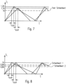
- Fig. 7 shows how two different operating points (increase of the current through the buck inductance when switch 5 is conductive) can actually result in a different peak current.
- a switch-off threshold value of 1A depending on the operating point, a real peak current of 1.2A or 1.1A can occur, even if the switch-off delay (which is component-dependent) is constant.
- the threshold values are now varied depending on the operating point in order to compensate for the switch-off delay.
- the switch-off threshold is set to 0.9A and in the second case to 0.8A. Due to the switch-off delay, the desired (e.g. pre-calculated) peak current of 1A is then obtained in both scenarios (with different gradients of the current through the inductance 4) and the switch-off delay is thus compensated in this respect.
- a calculated peak current I peak_comp is specified, which is calculated, for example, from a desired dimming value (current average) and a selected dead time, whereby this calculated peak current I peak_comp is slightly corrected by the output signal of a controller, for example an integral controller, deltalpk. The sum of both paths then results in a desired peak current of, for example, 1A.
- a correction value I pk_overshoot is now subtracted from this calculated desired target value. For small LED voltages with a steep current increase (large dI/dt), a correction is made with a relatively high value (for example, the value I pk_overshoot can be 0.2A).
- the correction is correspondingly less strong (then, for example, the value of I pk_overshoot can be 0.1A).
- the digital peak current value is converted into an analog threshold value in a DA converter DAC.
- the threshold value is fed to a comparator, which compares the threshold value with the actual voltage drop, for example, across a shunt (measuring resistor), whereby the voltage drop across the shunt represents the current through the buck inductance.
- the comparator switches its output, which leads to the buck switch 5 being switched off.
- the factor "I peak_overshoot” is determined as a function of the measured LED voltage V LED , for example according to an analytical function or a stored table which defines the function, for example according to Fig. 10
- other possibilities can also be used to determine information regarding the steepness of the current rise through the switch 5.
- Possible options include the use of at least one of the value of the inductance 4, the input voltage V bus or the output voltage V LED as well as any combination thereof.
- the correction factor I peak_overshoot is calculated continuously or at regular intervals.
- L denotes the value of the inductance 4 of the clocked converter 1.
- the switch-on time t on can of course simply be reduced by the switch-off delay t doff in order to compensate for the negative effect of the switch-off delay t doff .
- Fig. 11 shows a time curve of a given load current I avg_nom .
- Fig. 11 only a section of the dimming process is shown graphically. For the complete dimming process, the value reached on the y-axis at the end of the dimming process has fallen to exactly 1% of the initial value.
- Fig. 11 the target dimming value is plotted in the form of a nominal average load current L avg_nom .
- the dimming process for the lighting circuit 6 is characterized by a desired falling curve 10 of the nominal average load current I avg_nom , which the clocked converter 1 provides at its output as an actual value of the average load current L avg that corresponds as closely as possible to the nominal value I avg_nom .
- Fig. 12 shows associated with the time course 10 of the specified load current I avg_nom after Fig. 11 , calculated values for the dead time t dead_dom and set values for the dead time t dead .
- On the abscissa of the Fig. 12 is the time t for the time segment of the dimming process after Fig. 11 applied.
- the calculated dead time t dead_nom shows a rising curve 11 in the opposite direction to the falling curve 10 of the nominal average load current I avg_nom .
- the clocked converter 1 generates the falling load current I avg with an increase in the calculated dead time t dead_nom . Since the switch 5 is only to be switched on again at discretely spaced times, the actually set dead time t dead is only increased in discrete steps. This leads to the Fig. 12 shown step-like increasing curve 12 of the dead time t dead over the time t for the time segment of the dimming process of the illuminant section 6 in Fig. 11 .
- Fig. 12 It can be seen that the zero crossing of the inductance current I L closest to the calculated (nominal) dead time t dead_nom is always selected, thus determining the current value for t dead .
- Fig. 12 shows for all transitions from a lower value of the dead time t dead to a next higher value of the dead time t dead that the threshold is at 50% of a period of the oscillation process of the clocked converter 1. In terms of time, this corresponds exactly to half the distance between two "valleys", i.e. two negative half-waves of the inductance current I L or half a period of the resonance oscillation.
- Fig. 12 shows furthermore that in three transitions 12.1 of the four transitions shown in the curve 12 of the dead time t dead to a next higher value of the dead time t dead a A short-term toggle occurs between two adjacent zero crossings with a positive gradient.
- This short-term change between adjacent discrete restart times is based on a non-ideal determination of the peak current I peak in conjunction with a frequent change of the positive zero crossing of the inductance current I L closest to the calculated restart time.
- the detection of the valleys is also subject to fluctuations.
- the detected possible restart times fluctuate. This leads to short-term fluctuations in the average load current L avg and thus I LED , which can be perceived, for example, as flickering of the light output of the lamp section 6.
- FIG. 13 shows, assigned to the time course of the specified load current I avg_nom after Fig. 11 , calculated values for a dead time t dead_dom and set values for the dead time t dead after a further improved design with a hysteresis.
- the predetermined value is in the embodiment according to Fig. 13 to 10/16 or 62.5%. This means that for the dimming process in the direction of a lower light output or a lower average load current I avg , a shorter dead time t dead adjacent to the calculated dead time t dead_nom remains set until the calculated dead time t dead_nom deviates from the currently selected and set dead time t dead by more than 10/16 of the period of the resonance oscillation.
- Fig. 13 shows in the illustrated step-like course 13 of the dead time t dead the suppression of the short-term changes achieved by means of the introduced hysteresis during the transitions 12.1 of the course 12 of the dead time t dead to a next higher value of the dead time t dead in Fig. 12 .
- the hysteresis introduced in the above-discussed design of the clocked converter 1 also means that different operating points of the clocked converter 1 can result for a specific dimming value of the load current I avg_nom .
- the different operating points are each characterized by a set dead time t dead and a set peak current I peak . This is explained with reference to Fig. 16 further explained.
- Fig. 14 shows two further time courses of the specified average load current I avg_nom for the clocked converter 1 over the time t plotted in the direction of the abscissa.
- the specified average load current is given in representative digital values.
- the first curve 14 represents a dimming process towards a lower average load current I avg .
- the second curve 15 represents a dimming process towards a higher average load current I avg .
- the first curve 14 of the specified average load current I avg_nom and the second curve 15 of the specified average load current I avg_nom intersect at an intersection point 16.
- Intersection point 16 is characterized by an associated value of the specified average load current I avg_nom, which is part of both the curve 14 and the curve 15 of the dimming processes of the average load current I avg .
- Fig. 15 shows the time curves 14, 15 of the specified load current according to Fig. 14 calculated values for the dead time t dead_dom and set values for the dead time t dead with a hysteresis.
- the first curve 16 of the calculated mean dead time t dead_nom represents the calculated dead time t dead_nom for the second curve 15 of the specified mean load current I avg_nom for a dimming process in the direction of a higher mean load current I avg .
- Curve 17 is the actually set dead time t dead associated with the first curve 16 of the calculated average dead time t dead_nom .
- the dead time t dead decreases as time t increases. This increases the dimming value towards a higher light output of the lamp section 6 due to an increasing average load current I avg .
- the second curve 18 of the calculated mean dead time t dead_nom represents the calculated dead time for the first curve 14 of the specified mean load current I avg_nom for a dimming process in the direction of a reduced mean load current I avg . This reduces the dimming value towards a weaker light output of the luminous element section 6 due to a decreasing average load current I avg .
- the curve 19 is the actually set dead time t dead to the second curve 18 of the calculated average dead time t dead_nom corresponding to a dimming process towards smaller dimming values.
- a change of the selected zero crossing of the inductance current I L as the restart time of the switch 5 is carried out by the control circuit 2 if the time interval between the calculated theoretical restart time and the currently selected restart time is greater in magnitude than the product of the hysteresis factor k and the period of the resonance oscillation of the clocked converter 1.
- the period of the resonance oscillation of the clocked converter 1 corresponds to the time interval between two in-phase current values of the inductance current I L during the resonance oscillation during the dead time t dead .
- Fig. 15 the time interval between two in-phase current values of the inductance current I L during the resonance oscillation corresponds to a height of a step of the curves 17, 19 of the set dead time t dead in the direction of the ordinate of the Fig. 15 .
- the height 20 is in Fig. 15 in counter values, corresponding to a standardized time.
- a change of the selected restart time takes place in the Fig. 15 selected embodiment with a hysteresis factor k of approximately 0.625. This can be seen from the fact that the change does not occur at half, i.e. 0.5 or 50% of the step height 20, which would correspond to the selection of the zero crossing with a positive gradient of the inductance current I L that is closest in time to a calculated switch-on time, but after approximately 0.625 or 62.5% corresponding to the first section 21 in the curve 16 for decreasing dead time t dead or the section 22 of the curve 18 for increasing dead time t dead .
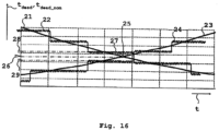
- Fig. 16 represents calculated values for the dead time t dead _dom and set values for the dead time t dead with a hysteresis for temporally increasing and for temporally decreasing values of the specified load current in a section.
- the different operating points are set depending on whether the control circuit 2 starts from a lower or a higher dead time t dead_nom or t dead and reaches a current target dimming value, and thus a current nominal average load current I avg_nom , a correspondingly calculated current dead time t dead _nom or t dead as the restart time for the switch 5 and the calculated peak current I peak_nom as the switch-off threshold for the switch 5.
- a predetermined average load current I avg with an average current of 100 mA is to be provided by the switch-mode converter 1.
- the switch 5 of the clocked converter 1 is therefore switched on again when the inductance current I buck passes through zero with a positive gradient of the coil current I L in the fourth period of the resonance oscillation after the switch 5 is switched off.
- the switch 5 is switched off at the first operating point when a peak current I peak with a current of 300 mA is reached.
- a second operating point is characterized by a dead time t dead with a duration of five periods of the resonance oscillation.
- the switch 5 of the clocked converter 1 is therefore switched on again when the inductance current I L passes through zero with a positive gradient of the inductance current I L in the fifth period of the resonance oscillation after the switch 5 is switched off.
- the switch 5 is switched off in the second operating point when a peak current I peak with a current of 330 mA is reached.
- Fig. 16 shows a value 26 of the dead time t dead which is determined by an increasing dimming curve of the average load current I avg and a correspondingly falling curve 21 of the dead time t dead_nom is achieved. This results in a stepped curve 22 of the set dead time t dead .
- the control circuit 2 provides Fig. 16 the dead time with a hysteresis.
- the hysteresis can, for example, be 62.5% of the period of the resonance oscillation of the clocked converter 1.
- the corresponding value 26 of the dead time t dead can alternatively be achieved via a falling dimming curve of the average load current I avg and a correspondingly rising curve 23 of the dead time t dead_nom . This results in a step-like rising curve 24 of the dead time t dead .
- the control circuit 2 can determine the switch-off threshold for the peak current I peak according to the different values for the dead time t dead1 28 , t dead2 29 to I peak1 or I peak2 in order to achieve the same setpoint value I avg nom with the current actual value of the load current I avg .
- the discussed implementation of the hysteresis for determining a switch-on time of the switch 5 is carried out with an equal hysteresis factor k for an increasing and a decreasing dimming curve of the load current I avg .
- hysteresis factors with different values can be selected for increasing and decreasing dimming curves of the load current I avg .
Landscapes
- Dc-Dc Converters (AREA)
- Circuit Arrangement For Electric Light Sources In General (AREA)
Claims (13)
- Appareil de commande permettant la commande modulable de moyens d'éclairage (1), en particulier d'une ou plusieurs DEL,- présentant un circuit convertisseur (1) cadencé comprenant un élément de stockage d'énergie (4), un circuit de contrôle (2) et au moins un commutateur (5) cadencé à partir du circuit de contrôle (2),- dans lequel le circuit de contrôle (2) est conçu pour commander sélectivement le circuit convertisseur (1) au moins dans un mode critique ou dans un mode de fonctionnement par intervalles par contrôle du commutateur (5),- dans lequel le circuit de contrôle (2) est conçu pour régler, en fonctionnement par intervalles, un instant de remise en marche du commutateur (5) par incréments discrets dans l'une des plages temporelles après le premier passage par zéro, dans lesquelles un courant traversant l'élément de stockage d'énergie (4) effectue un passage par zéro croissant, etlors d'une modification incrémentielle de l'instant de remise en marche, pour réguler une grandeur de rétroaction influençant la puissance du moyen d'éclairage par une modification directe ou indirecte d'une durée de mise en marche du commutateur (5), etle circuit de contrôle (2) est conçu pour exécuter, dans le fonctionnement par intervalles, une modification de l'instant de remise en marche à un nouvel instant de remise en marche calculé différent d'un instant de remise en marche actuel du commutateur (5) uniquement lorsque le nouvel instant de remise en marche du commutateur (5) s'écarte de l'instant de remise en marche actuel d'une durée supérieure à une valeur prédéterminée, etcaractérisé en ce quela valeur prédéterminée est une durée supérieure à 55 %, et de préférence une durée supérieure à 62,5 %, de la période d'une oscillation de résonance du courant traversant l'élément de stockage d'énergie (4) pendant un temps mort du circuit convertisseur (1) cadencé.
- Appareil de commande selon la revendication 1,
dans lequel le circuit de contrôle (2) est conçu,- en cas de prolongation incrémentielle de l'instant de remise en marche, pour prolonger de manière incrémentielle la durée de mise en marche et pour effectuer une régulation avec la grandeur de contrôle « durée de mise en marche », et- en cas de réduction incrémentielle de l'instant de remise en marche, pour réduire de manière incrémentielle la durée de mise en marche et pour effectuer ensuite une régulation avec la grandeur de contrôle « durée de mise en marche ». - Appareil de commande selon l'une des revendications précédentes,dans lequel le circuit de contrôle (2) est conçu,pour effectuer une modification incrémentielle de l'instant de remise en marche lorsque la régulation avec la grandeur de contrôle « durée de mise en marche » entraîne des valeurs minimales ou maximales prédéfinies de la durée de mise en marche ou d'une grandeur qui l'influence.
- Appareil de commande selon l'une des revendications précédentes,dans lequel le circuit de contrôle (2) est conçu,pour prédéfinir la modification de la durée de mise en marche du commutateur (5) indirectement par prédéfinition d'un seuil de coupure pour le courant traversant le commutateur (5) ou directement par prédéfinition de la durée de mise en marche.
- Appareil de commande selon l'une des revendications précédentes,
dans lequel le circuit de contrôle (2) est conçu pour prolonger brusquement la valeur pour la durée de mise en marche du commutateur (5) lors d'une transition du mode critique au mode de fonctionnement par intervalles. - Appareil de commande selon l'une des revendications précédentes, comprenant un circuit pour la détection du passage par zéro du courant traversant l'élément de stockage d'énergie (4) du circuit convertisseur (1), en particulier d'un convertisseur abaisseur,
dans lequel le circuit présente un circuit à diodes connecté à un potentiel au niveau d'un point de connexion d'une diode (7) du convertisseur abaisseur et d'un commutateur (5) du convertisseur abaisseur, lequel circuit à diodes est conçu pour générer un signal de détection de préférence numérique dont le niveau de préférence logique varie lors du passage par zéro du courant traversant l'inductance (4). - Appareil de commande selon la revendication 6, présentant un bloc logiciel ou matériel qui est conçu pour empêcher le niveau du signal de détection de changer après un premier passage par zéro lors des passages par zéro suivants.
- Appareil de commande selon l'une des revendications 6 ou 7, dans lequel le circuit pour la détection du passage par zéro du courant traversant l'élément de stockage d'énergie (4) du circuit convertisseur (1) est conçu pour fournir le signal de détection au circuit de contrôle (2), et
dans lequel le circuit de contrôle (2) est de préférence réalisé comme un microcontrôleur, et le microcontrôleur est conçu pour déclencher le démarrage d'un compteur dans le microcontrôleur par un changement de niveau défini du signal de détection. - Appareil de commande selon l'une des revendications 6 à 8, présentant
un enroulement auxiliaire (L1-b) couplé magnétiquement à l'inductance (4) du convertisseur abaisseur et conçu pour générer un signal qui commute un transistor (Q30) générant un signal de captage lorsque le courant traversant l'inductance (4) atteint son point d'inversion inférieur. - Appareil de commande présentant un circuit selon la revendication 9, présentant en outre un circuit pour la détection du point d'inversion inférieur du courant traversant l'inductance (L4), qui est conçu pour fournir le signal de captage au circuit de contrôle (2), de préférence à un microcontrôleur.
- Appareil de commande selon la revendication 10,
dans lequel le circuit de contrôle (2) est un microcontrôleur et le microcontrôleur est réalisé pour déclencher, en réponse à un changement de niveau défini du signal de captage, le stockage d'une valeur de compteur actuelle d'un compteur dans le microcontrôleur. - Appareil de commande pour moyens d'éclairage (6) selon l'une des revendications précédentes, présentant en particulier un convertisseur abaisseur en guise de circuit convertisseur (1) côté primaire,dans lequel le circuit de contrôle (2) est conçu pour rendre le commutateur (5) à nouveau non conducteur après l'écoulement d'une durée prédéfinie ton ou lorsqu'un seuil de coupure du courant de commutateur croissant est atteint,dans lequel le circuit de contrôle (2) est conçu pour obtenir un signal de rétroaction qui reproduit la tension aux bornes des moyens d'éclairage (6) alimentés par l'appareil de commande,dans lequel le circuit de contrôle (2) est conçu pour régler la durée ton ou le seuil de coupure en fonction du signal de rétroaction.
- Appareil de commande pour moyens d'éclairage selon la revendication 12, dans lequel le circuit de contrôle (2) est conçu pour régler le seuil de coupure plus bas lorsque la tension aux bornes des moyens d'éclairage (6) est plus faible que lorsque la tension aux bornes des moyens d'éclairage (6) est plus élevée.
Applications Claiming Priority (4)
| Application Number | Priority Date | Filing Date | Title |
|---|---|---|---|
| AT21817 | 2017-09-29 | ||
| DE102017221786.3A DE102017221786A1 (de) | 2017-09-29 | 2017-12-04 | Lampenbetriebsgerät mit Konverter im DCM |
| DE202018104924.0U DE202018104924U1 (de) | 2017-09-29 | 2018-08-28 | Lampenbetriebsgerät mit Konverter in DCM |
| PCT/EP2018/075050 WO2019063333A1 (fr) | 2017-09-29 | 2018-09-17 | Dispositif de commande de lampe ayant un convertisseur en dcm |
Publications (2)
| Publication Number | Publication Date |
|---|---|
| EP3673714A1 EP3673714A1 (fr) | 2020-07-01 |
| EP3673714B1 true EP3673714B1 (fr) | 2025-01-01 |
Family
ID=63685946
Family Applications (1)
| Application Number | Title | Priority Date | Filing Date |
|---|---|---|---|
| EP18778838.5A Active EP3673714B1 (fr) | 2017-09-29 | 2018-09-17 | Dispositif de commande de lampe ayant un convertisseur en dcm |
Country Status (1)
| Country | Link |
|---|---|
| EP (1) | EP3673714B1 (fr) |
Citations (1)
| Publication number | Priority date | Publication date | Assignee | Title |
|---|---|---|---|---|
| DE102015203249A1 (de) * | 2015-02-24 | 2016-08-25 | Tridonic Gmbh & Co. Kg | Abwärtswandler zum Betreiben von Leuchtmitteln mit Spitzenstromwertsteuerung und Mittelstromwerterfassung |
-
2018
- 2018-09-17 EP EP18778838.5A patent/EP3673714B1/fr active Active
Patent Citations (1)
| Publication number | Priority date | Publication date | Assignee | Title |
|---|---|---|---|---|
| DE102015203249A1 (de) * | 2015-02-24 | 2016-08-25 | Tridonic Gmbh & Co. Kg | Abwärtswandler zum Betreiben von Leuchtmitteln mit Spitzenstromwertsteuerung und Mittelstromwerterfassung |
Also Published As
| Publication number | Publication date |
|---|---|
| EP3673714A1 (fr) | 2020-07-01 |
Similar Documents
| Publication | Publication Date | Title |
|---|---|---|
| EP2837259B1 (fr) | Methode pour alimenter un convertisseur resonant llc pour une source lumineuse, et convertisseur et source de puissance pour led correspondante | |
| EP3262896B1 (fr) | Régulateur pour faire fonctionner des moyens d'éclairage avec une commande de valeur d'intensité de pointe et détection de valeur moyenne d'intensité | |
| DE19531966C2 (de) | Stromversorgungsschaltung für eine Hochdruck-Entladungslampe | |
| DE10355670B4 (de) | Verfahren zur Ansteuerung eines Schalters in einer Leistungsfaktorkorrekturschaltung und Ansteuerschaltung | |
| EP3202235B1 (fr) | Convertisseur électronique de puissance cadencé | |
| DE102009038843A1 (de) | Entladungslampe-Beleuchtungsvorrichtung, Scheinwerfervorrichtung und ein diese aufweisendes Kraftfahrzeug | |
| WO2019063333A1 (fr) | Dispositif de commande de lampe ayant un convertisseur en dcm | |
| EP2795785A1 (fr) | Dispositif de commande pour un onduleur chargé par un réseau de charge résonant | |
| DE102014106869B4 (de) | LED-Beleuchtungsvorrichtung und Beleuchtungsgerät | |
| EP1330945B1 (fr) | Ballast electronique avec circuit en pont integral | |
| EP1647087B1 (fr) | Dispositif de commande servant a commander un commutateur de charge dans un regulateur a decoupage et procede pour commander un commutateur de charge | |
| EP3673714B1 (fr) | Dispositif de commande de lampe ayant un convertisseur en dcm | |
| EP1901592B1 (fr) | Ballast électronique doté d'une commande à onduleur asymétrique | |
| DE10209631A1 (de) | Elektronische Schaltung und Verfahren zur Energieversorgung einer Hochdruckgasentladungslampe | |
| EP2266374B1 (fr) | Régulation de puissance de lampes à décharge dans des circuits en demi-pont ou en pont intégral | |
| AT16340U1 (de) | Getakteter Wandler für dimmbare Leuchtmittel mit dynamisch einstellbarem Filter | |
| DE102014221554B4 (de) | Pulsweitenmodulierte Ansteuerung einer getakteten Schaltung mit einstellbarer Leistungsübertragung | |
| DE202018104924U1 (de) | Lampenbetriebsgerät mit Konverter in DCM | |
| EP3460973A1 (fr) | Procédé de fonctionnement d'un convertisseur continu-continu pourvu de pluralité de branches partielles de puissance | |
| WO2019052974A1 (fr) | Appareil de commande pour une charge électrique et procédé | |
| EP3439159B1 (fr) | Réduction de fluctuations de flux lumineux dans une commande de valeur seuil d'un convertisseur cadencé activement | |
| EP4475409A1 (fr) | Procédé de fonctionnement d'un convertisseur continu-continu ainsi que convertisseur continu-continu | |
| DE102004038353B4 (de) | Ansteuerschaltung für einen Schalter in einem Schaltwandler und Schaltungsanordnung mit einem Schaltwandler und einer Last | |
| DE102018119333A1 (de) | Betriebsgerät und Steuerungsverfahren, insbesondere für LEDs | |
| DE102016202323A1 (de) | Treiberschaltung und Verfahren zum Ansteuern einer LED-Strecke |
Legal Events
| Date | Code | Title | Description |
|---|---|---|---|
| STAA | Information on the status of an ep patent application or granted ep patent |
Free format text: STATUS: UNKNOWN |
|
| STAA | Information on the status of an ep patent application or granted ep patent |
Free format text: STATUS: THE INTERNATIONAL PUBLICATION HAS BEEN MADE |
|
| PUAI | Public reference made under article 153(3) epc to a published international application that has entered the european phase |
Free format text: ORIGINAL CODE: 0009012 |
|
| STAA | Information on the status of an ep patent application or granted ep patent |
Free format text: STATUS: REQUEST FOR EXAMINATION WAS MADE |
|
| 17P | Request for examination filed |
Effective date: 20200326 |
|
| AK | Designated contracting states |
Kind code of ref document: A1 Designated state(s): AL AT BE BG CH CY CZ DE DK EE ES FI FR GB GR HR HU IE IS IT LI LT LU LV MC MK MT NL NO PL PT RO RS SE SI SK SM TR |
|
| AX | Request for extension of the european patent |
Extension state: BA ME |
|
| DAV | Request for validation of the european patent (deleted) | ||
| DAX | Request for extension of the european patent (deleted) | ||
| STAA | Information on the status of an ep patent application or granted ep patent |
Free format text: STATUS: EXAMINATION IS IN PROGRESS |
|
| 17Q | First examination report despatched |
Effective date: 20220825 |
|
| REG | Reference to a national code |
Ref country code: DE Ref legal event code: R079 Ipc: H05B0045375000 Ref document number: 502018015475 Country of ref document: DE Free format text: PREVIOUS MAIN CLASS: H05B0033080000 |
|
| RIC1 | Information provided on ipc code assigned before grant |
Ipc: H02M 3/156 20060101ALN20240717BHEP Ipc: H05B 45/375 20200101AFI20240717BHEP |
|
| GRAP | Despatch of communication of intention to grant a patent |
Free format text: ORIGINAL CODE: EPIDOSNIGR1 |
|
| STAA | Information on the status of an ep patent application or granted ep patent |
Free format text: STATUS: GRANT OF PATENT IS INTENDED |
|
| INTG | Intention to grant announced |
Effective date: 20240918 |
|
| GRAS | Grant fee paid |
Free format text: ORIGINAL CODE: EPIDOSNIGR3 |
|
| GRAA | (expected) grant |
Free format text: ORIGINAL CODE: 0009210 |
|
| STAA | Information on the status of an ep patent application or granted ep patent |
Free format text: STATUS: THE PATENT HAS BEEN GRANTED |
|
| AK | Designated contracting states |
Kind code of ref document: B1 Designated state(s): AL AT BE BG CH CY CZ DE DK EE ES FI FR GB GR HR HU IE IS IT LI LT LU LV MC MK MT NL NO PL PT RO RS SE SI SK SM TR |
|
| REG | Reference to a national code |
Ref country code: GB Ref legal event code: FG4D Free format text: NOT ENGLISH |
|
| P01 | Opt-out of the competence of the unified patent court (upc) registered |
Free format text: CASE NUMBER: APP_63552/2024 Effective date: 20241129 |
|
| REG | Reference to a national code |
Ref country code: CH Ref legal event code: EP |
|
| REG | Reference to a national code |
Ref country code: DE Ref legal event code: R096 Ref document number: 502018015475 Country of ref document: DE |
|
| REG | Reference to a national code |
Ref country code: IE Ref legal event code: FG4D Free format text: LANGUAGE OF EP DOCUMENT: GERMAN |
|
| REG | Reference to a national code |
Ref country code: LT Ref legal event code: MG9D |
|
| REG | Reference to a national code |
Ref country code: NL Ref legal event code: MP Effective date: 20250101 |
|
| PG25 | Lapsed in a contracting state [announced via postgrant information from national office to epo] |
Ref country code: NL Free format text: LAPSE BECAUSE OF FAILURE TO SUBMIT A TRANSLATION OF THE DESCRIPTION OR TO PAY THE FEE WITHIN THE PRESCRIBED TIME-LIMIT Effective date: 20250101 |
|
| PG25 | Lapsed in a contracting state [announced via postgrant information from national office to epo] |
Ref country code: FI Free format text: LAPSE BECAUSE OF FAILURE TO SUBMIT A TRANSLATION OF THE DESCRIPTION OR TO PAY THE FEE WITHIN THE PRESCRIBED TIME-LIMIT Effective date: 20250101 |
|
| PG25 | Lapsed in a contracting state [announced via postgrant information from national office to epo] |
Ref country code: PL Free format text: LAPSE BECAUSE OF FAILURE TO SUBMIT A TRANSLATION OF THE DESCRIPTION OR TO PAY THE FEE WITHIN THE PRESCRIBED TIME-LIMIT Effective date: 20250101 |
|
| PG25 | Lapsed in a contracting state [announced via postgrant information from national office to epo] |
Ref country code: ES Free format text: LAPSE BECAUSE OF FAILURE TO SUBMIT A TRANSLATION OF THE DESCRIPTION OR TO PAY THE FEE WITHIN THE PRESCRIBED TIME-LIMIT Effective date: 20250101 |
|
| PG25 | Lapsed in a contracting state [announced via postgrant information from national office to epo] |
Ref country code: NO Free format text: LAPSE BECAUSE OF FAILURE TO SUBMIT A TRANSLATION OF THE DESCRIPTION OR TO PAY THE FEE WITHIN THE PRESCRIBED TIME-LIMIT Effective date: 20250401 Ref country code: IS Free format text: LAPSE BECAUSE OF FAILURE TO SUBMIT A TRANSLATION OF THE DESCRIPTION OR TO PAY THE FEE WITHIN THE PRESCRIBED TIME-LIMIT Effective date: 20250501 |
|
| PG25 | Lapsed in a contracting state [announced via postgrant information from national office to epo] |
Ref country code: HR Free format text: LAPSE BECAUSE OF FAILURE TO SUBMIT A TRANSLATION OF THE DESCRIPTION OR TO PAY THE FEE WITHIN THE PRESCRIBED TIME-LIMIT Effective date: 20250101 |
|
| PG25 | Lapsed in a contracting state [announced via postgrant information from national office to epo] |
Ref country code: LV Free format text: LAPSE BECAUSE OF FAILURE TO SUBMIT A TRANSLATION OF THE DESCRIPTION OR TO PAY THE FEE WITHIN THE PRESCRIBED TIME-LIMIT Effective date: 20250101 Ref country code: PT Free format text: LAPSE BECAUSE OF FAILURE TO SUBMIT A TRANSLATION OF THE DESCRIPTION OR TO PAY THE FEE WITHIN THE PRESCRIBED TIME-LIMIT Effective date: 20250502 |
|
| PG25 | Lapsed in a contracting state [announced via postgrant information from national office to epo] |
Ref country code: GR Free format text: LAPSE BECAUSE OF FAILURE TO SUBMIT A TRANSLATION OF THE DESCRIPTION OR TO PAY THE FEE WITHIN THE PRESCRIBED TIME-LIMIT Effective date: 20250402 Ref country code: BG Free format text: LAPSE BECAUSE OF FAILURE TO SUBMIT A TRANSLATION OF THE DESCRIPTION OR TO PAY THE FEE WITHIN THE PRESCRIBED TIME-LIMIT Effective date: 20250101 |
|
| PG25 | Lapsed in a contracting state [announced via postgrant information from national office to epo] |
Ref country code: CZ Free format text: LAPSE BECAUSE OF FAILURE TO SUBMIT A TRANSLATION OF THE DESCRIPTION OR TO PAY THE FEE WITHIN THE PRESCRIBED TIME-LIMIT Effective date: 20250101 |
|
| PG25 | Lapsed in a contracting state [announced via postgrant information from national office to epo] |
Ref country code: SE Free format text: LAPSE BECAUSE OF FAILURE TO SUBMIT A TRANSLATION OF THE DESCRIPTION OR TO PAY THE FEE WITHIN THE PRESCRIBED TIME-LIMIT Effective date: 20250101 |
|
| REG | Reference to a national code |
Ref country code: DE Ref legal event code: R097 Ref document number: 502018015475 Country of ref document: DE |
|
| PG25 | Lapsed in a contracting state [announced via postgrant information from national office to epo] |
Ref country code: SM Free format text: LAPSE BECAUSE OF FAILURE TO SUBMIT A TRANSLATION OF THE DESCRIPTION OR TO PAY THE FEE WITHIN THE PRESCRIBED TIME-LIMIT Effective date: 20250101 |
|
| PG25 | Lapsed in a contracting state [announced via postgrant information from national office to epo] |
Ref country code: DK Free format text: LAPSE BECAUSE OF FAILURE TO SUBMIT A TRANSLATION OF THE DESCRIPTION OR TO PAY THE FEE WITHIN THE PRESCRIBED TIME-LIMIT Effective date: 20250101 |
|
| PGFP | Annual fee paid to national office [announced via postgrant information from national office to epo] |
Ref country code: DE Payment date: 20250926 Year of fee payment: 8 |
|
| PG25 | Lapsed in a contracting state [announced via postgrant information from national office to epo] |
Ref country code: IT Free format text: LAPSE BECAUSE OF FAILURE TO SUBMIT A TRANSLATION OF THE DESCRIPTION OR TO PAY THE FEE WITHIN THE PRESCRIBED TIME-LIMIT Effective date: 20250101 |
|
| PGFP | Annual fee paid to national office [announced via postgrant information from national office to epo] |
Ref country code: GB Payment date: 20250923 Year of fee payment: 8 |
|
| PGFP | Annual fee paid to national office [announced via postgrant information from national office to epo] |
Ref country code: FR Payment date: 20250925 Year of fee payment: 8 |
|
| PG25 | Lapsed in a contracting state [announced via postgrant information from national office to epo] |
Ref country code: EE Free format text: LAPSE BECAUSE OF FAILURE TO SUBMIT A TRANSLATION OF THE DESCRIPTION OR TO PAY THE FEE WITHIN THE PRESCRIBED TIME-LIMIT Effective date: 20250101 |
|
| PG25 | Lapsed in a contracting state [announced via postgrant information from national office to epo] |
Ref country code: RO Free format text: LAPSE BECAUSE OF FAILURE TO SUBMIT A TRANSLATION OF THE DESCRIPTION OR TO PAY THE FEE WITHIN THE PRESCRIBED TIME-LIMIT Effective date: 20250101 |
|
| PG25 | Lapsed in a contracting state [announced via postgrant information from national office to epo] |
Ref country code: SK Free format text: LAPSE BECAUSE OF FAILURE TO SUBMIT A TRANSLATION OF THE DESCRIPTION OR TO PAY THE FEE WITHIN THE PRESCRIBED TIME-LIMIT Effective date: 20250101 |
|
| PLBE | No opposition filed within time limit |
Free format text: ORIGINAL CODE: 0009261 |
|
| STAA | Information on the status of an ep patent application or granted ep patent |
Free format text: STATUS: NO OPPOSITION FILED WITHIN TIME LIMIT |
|
| 26N | No opposition filed |
Effective date: 20251002 |